T E M P O S O N I C S ® S E R I E S F e a t u r e s - MTS Sensors
T E M P O S O N I C S ® S E R I E S F e a t u r e s - MTS Sensors
T E M P O S O N I C S ® S E R I E S F e a t u r e s - MTS Sensors

You also want an ePaper? Increase the reach of your titles
YUMPU automatically turns print PDFs into web optimized ePapers that Google loves.
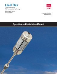
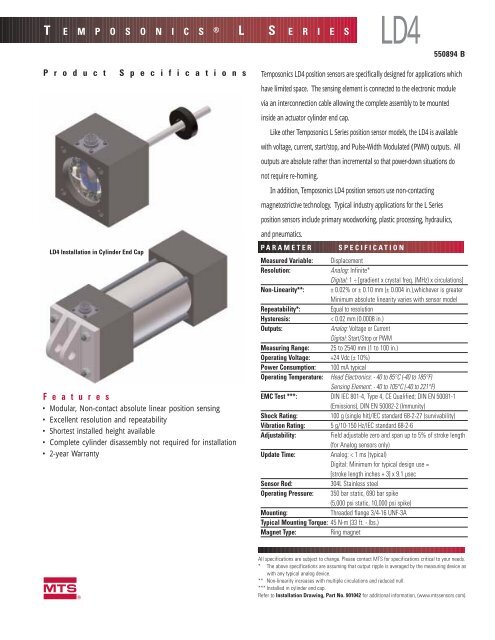
T E M P O S O N I C S ® L S E R I E SLD4550894 BP r o d u c t S p e c i f i c a t i o n sLD4 Installation in Cylinder End CapF e a t u r e s• Modular, Non-contact absolute linear position sensing• Excellent resolution and repeatability• Shortest installed height available• Complete cylinder disassembly not required for installation• 2-year WarrantyTemposonics LD4 position sensors are specifically designed for applications whichhave limited space. The sensing element is connected to the electronic modulevia an interconnection cable allowing the complete assembly to be mountedinside an actuator cylinder end cap.Like other Temposonics L Series position sensor models, the LD4 is availablewith voltage, current, start/stop, and Pulse-Width Modulated (PWM) outputs. Alloutputs are absolute rather than incremental so that power-down situations donot require re-homing.In addition, Temposonics LD4 position sensors use non-contactingmagnetostrictive technology. Typical industry applications for the L Seriesposition sensors include primary woodworking, plastic processing, hydraulics,and pneumatics.P ARAMETERSPECIFICATIONMeasured Variable: DisplacementResolution:Analog: Infinite*Digital: 1 ÷ [gradient x crystal freq. (MHz) x circulations]Non-Linearity**: ±0.02% or ± 0.10 mm (± 0.004 in.),whichever is greaterMinimum absolute linearity varies with sensor modelRepeatability*:Equal to resolutionHysteresis:< 0.02 mm (0.0008 in.)Outputs:Analog: Voltage or CurrentDigital: Start/Stop or PWMMeasuring Range: 25 to 2540 mm (1 to 100 in.)Operating Voltage: +24 Vdc (± 10%)Power Consumption: 100 mA typicalOperating Temperature: Head Electronics: - 40 to 85°C (-40 to 185°F)Sensing Element: - 40 to 105°C (-40 to 221°F)EMC Test ***: DIN IEC 801-4, Type 4, CE Qualified; DIN EN 50081-1(Emissions), DIN EN 50082-2 (Immunity)Shock Rating:100 g (single hit)/IEC standard 68-2-27 (survivability)Vibration Rating: 5 g/10-150 Hz/IEC standard 68-2-6Adjustability:Field adjustable zero and span up to 5% of stroke length(for Analog sensors only)Update Time:Analog: < 1 ms (typical)Digital: Minimum for typical design use =[stroke length inches + 3] x 9.1 µsecSensor Rod:304L Stainless steelOperating Pressure: 350 bar static, 690 bar spike(5,000 psi static, 10,000 psi spike)Mounting:Threaded flange 3/4-16 UNF-3ATypical Mounting Torque: 45 N-m (33 ft. - lbs.)Magnet Type:Ring magnetmAll specifications are subject to change. Please contact <strong>MTS</strong> for specifications critical to your needs.* The above specifications are assuming that output ripple is averaged by the measuring device aswith any typical analog device.** Non-linearity increases with multiple circulations and reduced null.*** Installed in cylinder end cap.Refer to Installation Drawing, Part No. 901042 for additional information, (www.mtssensors.com).
O U T P U T SDIGITAL OUTPUTSThe Temposonics L Series position sensors provide direct Start/Stop and PWMoutputs. The Start/Stop output consists of two differential pairs of signals,(based on the RS-422 standard), that use TTL voltage levels,(0 to 5 volts). One differential pair is used for Start, and the other for Stop.These differential signals provide for better noise immunity.NullpositionMagnetEach Start/Stop or PWM output style sensor is provided with its actualmeasured gradient value indicated on the sensor’s label. The gradient is theSTART/STOPStartTo controller, meter,or other device+ Start- Startinverse of the rate at which a pulse signal, (generated at the positionmagnet), propagates through the magnetostrictive waveguide inside thesensor’s rod, (about 9 microseconds per inch). As the position magnet ismoved further down the sensor rod, more time is required for the pulseTime between Start and Stoppulses is proportionalto magnet positionStop+ Stop- Stopsignals that are generated to travel back to the sensor’s electronics at thehead. To determine the absolute position of the position magnet it is onlynecessary to divide the difference in time between the Start signal and thePWMTo controller, meter,or other device+ Gate- GateStop signal by the gradient.Pulse width is proportionalto magnet positionThe PWM output provides the same elapsed time information, but ratherthan separate Start and Stop signals, it is represented on one differential pairof signals as a varying pulse width.For both Start/Stop and PWM standard resolution is 0.004 inches, (whenusing a 28 MHz counter). Higher resolutions are possible with increasedcirculations or with the use of higher resolution counters.ANALOG OUTPUTSThe Temposonics L Series position sensors provide direct analogoutputs, including voltage (0 to 10 Vdc, forward or reverse acting) andcurrent (4 to 20 mA or 0 to 20 mA, forward or reverse acting). Bothvoltage and current outputs allow 5% adjustments of zero and spansetpoints. Resolution is limited only by the output ripple. Since theoutputs are direct, no signal-conditioning electronics are needed wheninterfacing with controllers or meters.0 to 10 Vdc10 to 0 Vdc4 to 20 mA20 to 4 mA0 to 20 mA20 to 0 mATo controller, meter, or other deviceOutput proportionalto magnet position2
D I M E N S I O N SElectronics Module27.5 mm dia. (1.08 in.)54.7 mm dia.(2.15 in.)18.8 mm(0.74 in.)25.4 mm dia.(1.00 in.)5.8 mm (0.23 in.)50.8 mm(2.0 in.)Sensing Element & Pressure Housing50.8 mm (2.00 in.)NullPositionStroke LengthEnd ofStroke60.2 mm (2.37 in.)Dead Zone23.0 mm dia(0.91 in.)20.8 mm (0.82 in.)23.3 mm(0.92 in.)15.2 mm(0.60 in.)23.0 mm (0.91 in.)Position Magnet19.1 mm(0.75 in.)47.5 mm (1.87 in.) 3/4 - 16 UNF Threads8 mm dia. (0.313 in.)Typical Cylinder Installation24.6 mm(0.97 in.)A6-pin DINPanel Mount Connector17.2 mm dia.(0.68 in.)Section A-A24.6 mm(0.97 in.)10.0 mm (0.39 in.)3/4 - 16 UNF Threads76.2 mm(3.00 in.)54.99 + 0.13 mm dia.- 0.00(2.165 + 0.005- 0.000 in.)A76.2 mm (3.00 in.)6.1 mm (0.24 in.)24.1 mm(0.95 in.)19.1 mm (0.75 in.)59.3 mm (2.33 in.)NOTES:1) The LD4 is shown in a sample 2 inch bore NFPA cylinder end cap installation (not provided). This is the minimum recommended cylinder size for the LD4product. The dimension, 54.99 + 0.13/- 0.00 mm dia., for the cylinder end cap must be observed to provide proper support for the electronics module.Other dimensions shown are for reference only.2) Cylinder manufacturer must provide adequate method for end cap sealing to achieve desired ingress protection.3) Shown with standard 6-pin DIN panel mount connector option (see next page).4) Standard null spacing from pressure flange face is 50.8 mm (2.0 in.). Special null spacing of 25.4 mm (1.0 in.) is also available. Contact factoryfor details.3
W I R I N GCONNECTION TYPESConnector and Cable AssemblyAnalog Output:(Voltage or Current)Pin No. Wire Color Function1 Gray 0 to 10 Vdc,4 to 20 mA, 0 to 20 mA2 Pink Return for Pin 13 Yellow 10 to 0 Vdc,20 to 4 mA, or 20 to 0 mA4 Green Return for Pin 35 Red or Brown Customer Supplied Power (+ 24 Vdc)6 White DC GroundDigital Output:(PWM or Start/Stop)Pin No. Wire Color Function1 Gray (-) Gate for PWM, (-) Stop for Start/Stop2 Pink (+) Gate for PWM, (+) Stop for Start/Stop3 Yellow (+) Interrogation for PWM,(+) Start for Start/Stop4 Green (-) Interrogation for PWM,(-) Start for Start/Stop5 Red or Brown Customer Supplied Power (+ 24 Vdc)6 White DC GroundPanel Mount Connector(D6 Male)LD4Connector and Cable Assembly3.2 mm dia. (0.13 in.)4 PLPanel Mount Connector(D6 Male)Connectorto Electronics ModulePin 126 mm dia.(1.02 in.)20 mm dia.(0.79 in.)1 5623416.0 mm(0.63 in.)20 mm dia.(0.79 in.)26 mm(1.02 in.)17 mm dia.(0.67 in.)76 mm (3 in.),127 mm (5 in.)or203 mm (8 in.)5.8 mm(0.23 in.)3.4 mm(0.13 in.)NOTES:•Appropriate grounding of extension cable shield is required at the controller end.For Analog Output:•When using current (mA) outputs, only one output signal is provided, (as selected in the ordering guide). With voltageoutputs, both 0 to 10 Vdc and 10 to 0 Vdc output signals are provided.•Minimum load impedance for voltage outputs is 5K Ω.•Maximum load impedance for current output is 500 Ω. (Reference to Ground Only, see page 6)For Digital Output:•For single-ended interrogation, the unused interrogation lead must be connected to DC ground at the controller.•When using PWM with internal interrogation, both interrogation leads must be connected to DC ground.4
W I R I N GCABLE CONNECTORS (Field-installable D6 Female):Mates with Sensor Panel Mount D6 ConnectorD6 Straight-exit ConnectorPart No. 56070018 mm dia. (0.7 in.)54 mm (2.1 in.)D6 90° ConnectorPart No. 56077818 mm dia. (0.7 in.)38 mm (1.5 in.)54 mm (2.1 in.)EXTENSION CABLE WITH CONNECTOR(S) FOR D6 CONNECTION TYPESENSOR CONNECTION TYPED6 = Female connector (straight exit) for sensors with D6 connectorDA = Female connector (90° exit) for sensors with D6 connectorCABLE LENGTHSFor standard length cables up to 100 ft.005 = 5 ft.015 = 15 ft.025 = 25 ft.050 = 50 ft.100 = 100 ft.For custom length cables over 100 ft.__ __ __ = Cable Length (maximum cable length is dependent on the outputselected; consult <strong>MTS</strong> Applications Engineering.)CABLE TERMINATIONPO = Pigtail connectionD6M = 6-pin D6 Male connector (straight exit)5
I N S T A L L A T I O NTYPICAL WIRING FOR CURRENT OUTPUT (4-20 mA Loop)Controller4-20 mA Output4-20 mA Loop500 ΩMaxOutput ReturnCustomerSuppliedPower24 VdcDC GroundOptional connection to groundNOTES:• Sensor requires connection to customer supplied power and can not be loop-powered from controller.• The 4-20 mA current loop is powered only by the sensor.• The sensor’s Output Return connection is referenced to DC Ground, (connected internally). To avoid output errors the optional connection toground at the controller must be at the same potential as DC Ground.CYLINDER INSTALLATIONThe Temposonics LD4 position sensors are designedNullStandard: 50.8 mm (2.00 in.)Stroke LengthDead Zonefor installation into hydraulic cylinders. The sensor’shigh-pressure, stainless steel tube installs into a10 millimeter bore in the piston head and rodSeeNotes10 mm (0.39 in.) minimum Boreassembly as illustrated (right). Incorporation of theLD4 sensor requires modification of the cylinder endPiston Head & Rod AssemblySensor Rod8 mm dia. (0.313 in.)cap as indicated. Proper sealing of the end capsurrounding the electronics module is requiredto achieve the desired ingress protection.Sealed EndCap CoverThreads(3/4 - 16 UNF)Non-ferrous Spacer (Part No.: 400633). See notes.Position MagnetChamfered Rod Bushing(Customer provided, optional)NOTES:• The position magnet requires minimum distances away from ferrous metals to allow proper sensor output. The minimum distance from the front of themagnet to the cylinder end cap is 15 mm, (0.6 in.). The minimum distance from the back of the magnet to the position head is provided by thenon-ferrous spacer, i.e. 3.2 mm, (0.125 in.).• The illustration above represents a typical installation. Some installation requirements may be application specific.6
H O W T O O R D E RPOSITION SENSORWhen placing an order, build theSENSOR MODELLD4= Rod-style, detached electronics housingL D 4T12 or 4 digit code, dependingon the output selecteddesired model number using the modelnumber guide (right). A selection ofTemposonics LD4 sensor configurationsare available to meet the demands ofyour particular application.If you have any questions abouthow to apply <strong>MTS</strong> Temposonics positionsensors, please contact one of ourApplication Engineers or your local <strong>MTS</strong>distributor —they are available to helpyou design an effective position sensingsystem to fit your application.NOTES:•Mating connectors, extension cables,and magnets sold separately. Seepage 5.TPRESSURE HOUSING STYLE= US customary threads, and pressure tubeSTROKE LENGTH__ __ __ . __ U = Inches and tenths (Encode in 0.1 in. increments)or__ __ __ __ M = Millimeters (Encode in 5 mm increments)CONNECTION TYPEF01 = Connector and cable assembly, 3 inches longF02 = Connector and cable assembly, 5 inches longF03 = Connector and cable assembly, 8 inches long000 = No connector and cable assembly includedINPUT VOLTAGE1 = +24 Vdc, ± 10%STROKE LENGTH NOTES:• LD4 stroke range = 1 - 100 in.(25 - 2540 mm)OUTPUTV0 = 0 to 10 Vdc and 10 to 0 VdcA0 = 4 to 20 mAA1 = 20 to 4 mAA2 = 0 to 20 mAA3 = 20 to 0 mARO = Start/StopD __ __ __ = Pulse-Width Modulated (PWM) (Fill in three blanks with the following codes.)a b ca) Interrogation b,c) CirculationsE = External__ __ = Desired number of circulationsI = Internal (Range = 1 to 15; encode as 01to 15 . Refer to Tables A and B).TABLE A:Circulation Count vs. Resolution for PWMOutput (Based on 28 MHz counter)ResolutionCirculation Count*0.00026 in. (0.0066mm) 150.0005 in. (0.0127 mm) 80.001 in. (0.025 mm) 40.002 in. (0.051 mm) 20.004 in. (0.102 mm) 1TABLE B:Maximum Circulation Count vs Strokefor PWM Output w/Internal InterrogationStroke Maximum Circulation Count≤ 84 in. (2134 mm) 15> 84.1 in. (2136 mm) 1*Limited by stroke length for sensors configured for internal interrogation. (Refer to Table B.)7
H O W T O O R D E RACCESSORIESDescription Part No. NotesMagnet Spacer 400633 For use with standard ring magnet Part No. 201542Magnet Mounting Screws 560357 Used to mount standard ring magnet Part No. 201542(4 screws required)Power Supply (24/28 Vdc, 0.5 A) 380009 Open frame styleLD4 O-ring (spare) 560705 For sealing Temposonics LD4 pressure tube in the cylinder (black)D6 Field-installable Connector 560700 Female, straight-exit, see page 5D6 Field-installable Connector 560778 Female, 90º, see page 5Cable, Standard Type 530026 3 twisted pairs, shielded, PVC jacket, specify desired lengthin feetMAGNETSMagnets must be ordered separately withTemposonics LD4 sensors. A variety of magnet styles(right) are available to meet your particularapplication demands. The standard ring magnet(Part No. 201542) is suitable for most applications .Standard Ring MagnetPart No. 201542ID: 13.5 mm (0.53 in.)OD: 32.8 mm (1.29 in.)Thickness: 7.9 mm (0.312 in.)4 Holeseach 3.9 mm dia. (0.15 in.)90°apart on 23.9 mm dia.(0.94 in.)Magnet Spacer(Non-ferrous Spacerfor Use with Standard RingMagnet)Part No. 400633ID: 14.3 mm (0.56 in.)O.D.: 31.8 mm (1.25 in.)Thickness: 3.2 mm (0.125 in.)4 Holeseach 3.9 mm dia. (0.15 in.)90° apart on 23.9 mm dia. (0.94 in.)Ring MagnetPart No. 400533Ring MagnetPart No. 401032Small Ring MagnetPart No. 252406ID: 13.5 mm (0.53 in.)O.D.: 25.4 mm (1.0 in.)Thickness: 7.9 mm (0.312 in.)(For use with strokes< 3050 mm or 120 in.)ID: 13.5 mm (0.532 in.)O.D.: 17.4 mm (0.685 in.)Thickness: 7.9 mm (0.312 in.)(For use with strokes< 1525 mm or 60 in.)ID: 9.7 mm (0.38 in.)OD: 13.5 mm (0.53 in.)Thickness: 5.8 mm (0.23 in.)(For use on 7 or 8 mm O.D.sensor rods, for strokes upto 100 in.)mPioneers,Innovators,Leaders inMagnetostrictiveSensingSENSORSG R O U PUNITED STATES<strong>MTS</strong> Systems Corporation<strong>Sensors</strong> Division3001 Sheldon DriveCary, NC 27513Tel: 800.633.7609Fax: 919.677.0200Web: www.mtssensors.comEmail:displacement@mtssensors.comGERMANY<strong>MTS</strong> Systems Corporation<strong>Sensors</strong> TechnologieAuf dem Schuffel 9, D-58513 Lüdenscheid, GermanyPostfach 8130 D-58489 Lüdenscheid, GermanyTel: + 49.2351.95870Fax: + 49.2351.56491Web: www.mtssensor.deJAPAN<strong>MTS</strong> Systems Corporation<strong>Sensors</strong> Technologie JapanUshikubo Bldg.737 Aihara-cho, Machida-shiTokyo 194-0211, JapanTel: + 81 (42) 775.3838Fax:+ 81 (42) 775.5512<strong>MTS</strong> is a registered trademark of <strong>MTS</strong> Systems CorporationTemposonics is a registered trademark of <strong>MTS</strong> Systems Corporation.© 2003 <strong>MTS</strong> Systems CorporationAll Temposonics sensors are covered by US patent number 5,545,984 and others. Additional patents are pending.All other trademarks are the property of their respective owners.Part Number: 6-03 550894 Revision B