HW-D-0617 - STI - Specified Technologies Inc
HW-D-0617 - STI - Specified Technologies Inc
HW-D-0617 - STI - Specified Technologies Inc

You also want an ePaper? Increase the reach of your titles
YUMPU automatically turns print PDFs into web optimized ePapers that Google loves.
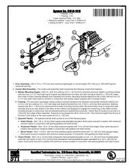
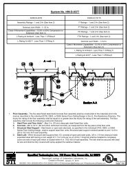
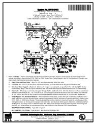
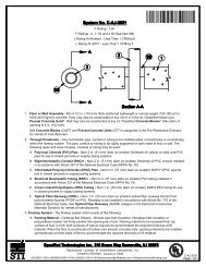
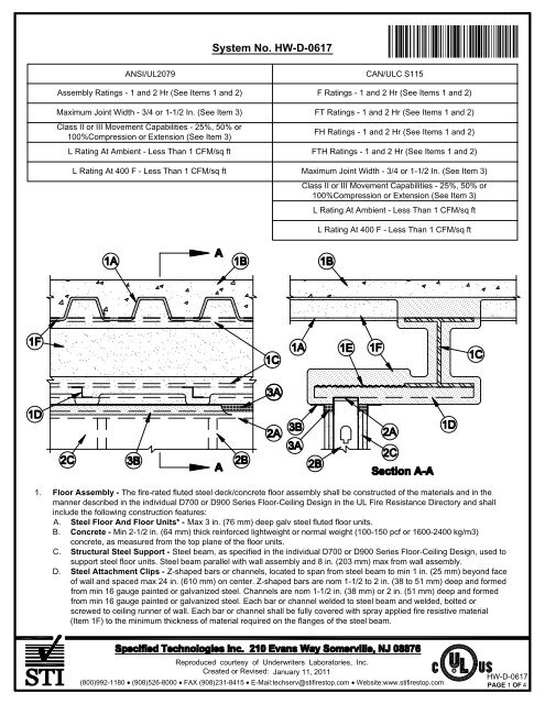
F. Spray-Applied Fire Resistive Material* - After installation of steel attachment clip and steel lath (Items 1AD and 1AE)surfaces of the roof deck to be sprayed with the thickness of material specified in the individual P700 Series Design. ForP900 Series Designs structural steel supports, steel attachment clip and steel lath only to be sprayed in accordance withthe specifications in the individual P900 Series Design. The flutes of the steel roof deck are to be filled with materialacross the entire top flange of the steel beam. Each bar or channel attachment clips (Item 1AD) shall be fully coveredwith spray applied fire resistive material to the minimum thickness of material required on the flanges of the steel beam.The thickness of material applied to the expanded steel lath shall be sufficient to completely fill the spaces between thebar/channel attachment clip above the wall. Additional material shall be applied to the web of the steel beam on eachside of the wall. The min total thickness of material applied to each side of the steel beam web shall be 13/16 in. (21 mm)for 1 hr fire rated assemblies and 1-3/8 in. (35 mm) for 2 hr fire rated assemblies.W R GRACE & CO - CONN - Type MK-6/HY, MK-6/HYES, MK-65 and RGISOLATEK INTERNATIONAL - Type 300 or Type IISOUT<strong>HW</strong>EST FIREPROOFING PRODUCTS CO - Type 5, Type 5GPThe hourly fire rating of the roof assembly shall be equal or greater than the hourly fire rating of the wallassembly.2. Wall Assembly - The 1 or 2 hr fire rated gypsum board/steel stud wall assembly shall be constructed of the materials and inthe manner described in the individual U400, V400 or W400 Series Wall and Partition Design in the UL Fire ResistanceDirectory and shall include the following construction features:A. Steel Floor and Ceiling Runners - Floor and ceiling runners of wall assembly shall consist of galv steel channels sizedto accommodate steel studs (Item 2B). Ceiling runner to be provided with min 1-1/4 in. (32 mm) to max 3 in. (76 mm)flanges. Flange height of ceiling runner shall be min 1/4 in. (6 mm) greater than max extended joint width. Ceiling runneris secured to steel attachment clip (Item 1D) with steel fasteners or welds spaced max 24 in. (610 mm) OC. Ceilingrunner to be installed parallel with structural steel support and located such that a max clearance of 8 in. (203 mm) ispresent between the finished wall and the flange of the steel beam (Item 1C).A1. Light Gauge Framing* - Slotted Ceiling Runner - Slotted ceiling runner may be used as an alternate to the ceilingrunner in Item 2A. Slotted ceiling runner to consist of galv steel channel with slotted flanges sized to accommodate steelstuds (Item 2B). Ceiling runner installed perpendicular to direction of fluted steel floor or roof deck and secured to valleyswith steel masonry anchors spaced max 24 in. (610 mm) OC.BRADY CONSTRUCTION INNOVATIONS INC, DBA SLIPTRACK SYSTEMS - SLP-TRK, SLPTRK325B. Studs - Steel studs to be min 3-1/2 in. (89 mm) wide. Studs cut 1/2 in. to 1-1/4 in. (13 to 32 mm) less in length thanassembly height with bottom nesting in and secured to floor runner. Studs to nest in ceiling runner without attachment.C. Gypsum Board* - Gypsum board sheets installed to a min total 5/8 in. (16 mm) or 1-1/4 in. (32 mm) thickness on eachside of wall for 1 and 2 hr fire rated assemblies, respectively. Wall to be constructed as specified in the individual U400,V400 or W400 Series Design in the UL Fire Resistance Directory except that a max 1-1/2 in. (38 mm) gap shall bemaintained between the top of the gypsum board and the bottom plane of the spray applied fire resistive material on thesteel attachment clip (Item 1D) on both sides of the wall assembly.The hourly fire rating of the joint system is equal to the hourly fire rating of the wall.3. Joint System - Max separation between bottom plane of spray-applied fire resistive material on the steel attachmentclip (Item 1D) and the top of the gypsum board is 3/4 or 1-1/2 in. (19 or 38 mm). When Item 3A1 is used in lieu of themineral wool strips described in Item 3A, the maximum joint width is 3/4 in. (19 mm) and the movement capability ofthe joint system is 100 percent compression or extension. Otherwise, the movement capability of the joint system is50 percent compression or extension when spray sealant (Item 3B) is used or 25 percent compression only whensealant (Item 3C) is used. The joint system shall consist of forming and fill materials, as follows:Reproduced courtesy of Underwriters Laboratories, <strong>Inc</strong>.Created or Revised: January 11, 2011(800)992-1180 (908)526-8000 FAX (908)231-8415 E-Mail:techserv@stifirestop.com Website:www.stifirestop.comR<strong>HW</strong>-D-<strong>0617</strong>PAGE 3 OF 4
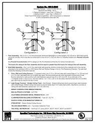
A. Forming Material* - Nom 4 pcf (64 kg/m3) density mineral wool batt insulation. Sections of mineral wool batt cut to athickness equal to the overall thickness of gypsum board and compressed a min of 50 percent into the gap between thetop of the gypsum board and the bottom plane of the spray applied fire resistive material on the steel attachment clip(Item 1D) on both sides of the wall assembly.IIG MINWOOL L L C - MinWool-1200 SafingROCK WOOL MANUFACTURING CO - Delta Safing InsulationROCKWOOL MALAYSIA SDN BHD - SAF Mineral WoolROXUL INC - SAF Mineral WoolTHERMAFIBER INC - Type SAFA1. Forming Material* - (Not Shown) - As an option to Item 3A, nom 3/16 in. (4.8 mm) thick by 4 in. (102 mm) high jointforming material profile installed on both sides of the wall assembly. Profile installed by first marking a line across the topof the wall 3 in. (76 mm) below the bottom plane of the steel floor or roof deck valleys. Joint profile material positionedwith its top edge against both the underside of the spray-applied fire-resistive material with its bottom edge on the linescribed on the wall assembly. Bottom of the joint profile attached to gypsum board with nom 1/2 in. (13 mm) long steelstaples spaced not greater than 8 in. (203 mm) OC. Adjoining lengths of profile to overlap approx 3/4 in. (19 mm) atrabbeted ends.SPECIFIED TECHNOLOGIES INC - SpecSeal Speed Flex Joint ProfileB. Fill, Void or Cavity Material* - Sealant - A min 1/8 in. (3 mm) wet thickness (min 1/16 in. or 1.6 mm dry thickness) of fillmaterial applied on each side of wall to completely cover forming material and to overlap min 1/2 in. (13 mm) onto walland min 2 in. (51 mm) onto spray-applied fire resistive material.SPECIFIED TECHNOLOGIES INC - SpecSeal AS200 Elastomeric SprayC. Fill, Void or Cavity Material* - Sealant - (Not Shown) - As an alternate to Items 3A and 3B, min 5/8 in. (16 mm) depthof sealant applied within joint flush with each side of wall.SPECIFIED TECHNOLOGIES INC - SpecSeal ES Sealant*Bearing the UL Classification MarkReproduced courtesy of Underwriters Laboratories, <strong>Inc</strong>.Created or Revised: January 11, 2011(800)992-1180 (908)526-8000 FAX (908)231-8415 E-Mail:techserv@stifirestop.com Website:www.stifirestop.comR<strong>HW</strong>-D-<strong>0617</strong>PAGE 4 OF 4