OMAL- Angle seat valve
OMAL- Angle seat valve
OMAL- Angle seat valve

You also want an ePaper? Increase the reach of your titles
YUMPU automatically turns print PDFs into web optimized ePapers that Google loves.
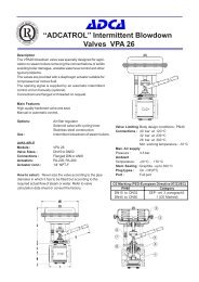
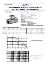
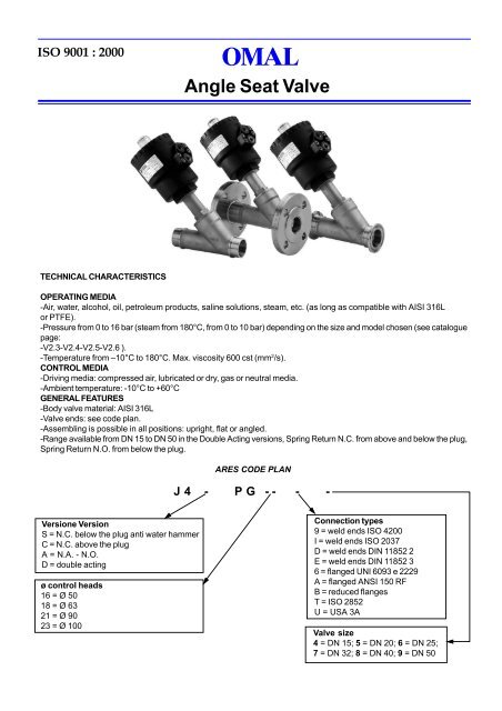
ISO 9001 : 2000<strong>Angle</strong> Seat ValveTECHNICAL CHARACTERISTICSOPERATING MEDIA-Air, water, alcohol, oil, petroleum products, saline solutions, steam, etc. (as long as compatible with AISI 316Lor PTFE).-Pressure from 0 to 16 bar (steam from 180°C, from 0 to 10 bar) depending on the size and model chosen (see cataloguepage:-V2.3-V2.4-V2.5-V2.6 ).-Temperature from –10°C to 180°C. Max. viscosity 600 cst (mm 2 /s).CONTROL MEDIA-Driving media: compressed air, lubricated or dry, gas or neutral media.-Ambient temperature: -10°C to +60°CGENERAL FEATURES-Body <strong>valve</strong> material: AISI 316L-Valve ends: see code plan.-Assembling is possible in all positions: upright, flat or angled.-Range available from DN 15 to DN 50 in the Double Acting versions, Spring Return N.C. from above and below the plug,Spring Return N.O. from below the plug.ARES CODE PLANJ 4 - P G - - - -Versione VersionS = N.C. below the plug anti water hammerC = N.C. above the plugA = N.A. - N.O.D = double actingø control heads16 = Ø 5018 = Ø 6321 = Ø 9023 = Ø 100Connection types9 = weld ends ISO 4200I = weld ends ISO 2037D = weld ends DIN 11852 2E = weld ends DIN 11852 36 = flanged UNI 6093 e 2229A = flanged ANSI 150 RFB = reduced flangesT = ISO 2852U = USA 3AValve size4 = DN 15; 5 = DN 20; 6 = DN 25;7 = DN 32; 8 = DN 40; 9 = DN 50
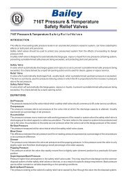
ARESFLANGES ACCORDING TO UNI 6093 UNI 2229DIMENSIONSøEDClockwise rotationControl head adjustable at 360 oA16 16Standard production1212M51/8” ISO 228BC45 o L45 oøQøMøNøPøRHLHF** face to face according to DIN 3202 part F1DN Control A B C D øE F * H L øM øN øP øQ øRhead15 Ø 50 181 156 204 44 70 130 14 12 18.1 45 95 65 1420 Ø 50 191 160 213 44 70 150 16 14 23.7 58 105 75 1420 Ø 63 209 178 231 50.5 84.4 150 16 14 23.7 58 105 75 1425 Ø 50 196 164 222 44 70 160 16 14 29.7 68 115 85 1425 Ø 63 215 182 240 50.5 84.4 160 16 14 29.7 68 115 85 1425 Ø 90 255 222 280 66.2 116.4 160 16 14 29.7 68 115 85 1432 Ø 50 201 168 238 44 70 180 16 14 38.4 78 140 100 1832 Ø 63 219 186 256 50.5 84.4 180 16 14 38.4 78 140 100 1832 Ø 90 259 226 296 66.2 116.4 180 16 14 38.4 78 140 100 1832 Ø 110 295 261 331 77.4 140.6 180 16 14 38.4 78 140 100 1840 Ø 63 227 190 265 50.5 84.4 200 16 13 44.3 88 150 110 1840 Ø 90 267 230 305 66.2 116.4 200 16 13 44.3 88 150 110 1840 Ø 110 303 266 341 77.4 140.6 200 16 13 44.3 88 150 110 1850 Ø 63 242 200 283 50.5 84.4 230 18 15 55.7 102 165 125 1850 Ø 90 282 240 323 66.2 116.4 230 18 15 55.7 102 165 125 1850 Ø 110 318 276 359 77.4 140.6 230 18 15 55.7 102 165 125 18Standard executions are in bold
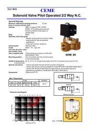
Clockwise rotationøEDARESFLANGES ACCORDING TO ANSI 150 RFDIMENSIONSControl head adjustable at 360 oA16 1612Version on request12M51/8” ISO 228B45 o LC45 oøQøMøNøPøRLHHF*G* face to face according to ASME B16.10 A1DN Control A B C D øE F H L øM øN øP øQ øRhead15 Ø 50 181 156 204 44 70 108 12 10.4 18.1 35 89 61 1620 Ø 50 191 160 213 44 70 117.5 12 11.4 23.7 43 98 70 1620 Ø 63 209 178 231 50.5 84.4 117.5 13 11.4 23.7 43 98 70 1625 Ø 50 196 164 222 44 70 127 15 13.4 29.7 51 108 80 1625 Ø 63 215 182 240 50.5 84.4 127 15 13.4 29.7 51 108 80 1625 Ø 90 255 222 280 66.2 116.4 127 15 13.4 29.7 51 108 80 1632 Ø 50 201 168 238 44 70 140 16 14.4 38.4 64 118 89 1632 Ø 63 219 186 256 50.5 84.4 140 16 14.4 38.4 64 118 89 1632 Ø 90 259 226 296 66.2 116.4 140 16 14.4 38.4 64 118 89 1632 Ø 110 295 261 331 77.4 140.6 140 16 14.4 38.4 64 118 89 1640 Ø 63 227 190 265 50.5 84.4 165 18 16.4 44.3 73 127 99 1640 Ø 90 267 230 305 66.2 116.4 165 18 16.4 44.3 73 127 99 1640 Ø 110 303 266 341 77.4 140.6 165 18 16.4 44.3 73 127 99 1650 Ø 63 242 200 283 50.5 84.4 178 19 17.4 55.7 93 152 127 1950 Ø 90 282 240 323 66.2 116.4 178 19 17.4 55.7 93 152 127 1950 Ø 110 318 276 359 77.4 140.6 178 19 17.4 55.7 93 152 127 19Standard executions are in bold
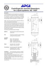
Clockwise rotationøEDARESREDUCED FLANGESDIMENSIONSControl head adjustable at 360 oA16 161212Special production fortextile industryM51/8” ISO 228BC 45 o F*45 oøQøRøMøPHHG* to be defined according to customer’s needDN Control A B C D øE F * H øM øN øP øQ øRhead15 Ø 50 181 156 204 44 70 105 7 18.1 35 70 50 720 Ø 50 191 160 213 44 70 120 8 23.7 43 75 55 920 Ø 63 209 178 231 50.5 84.4 120 8 23.7 43 75 55 925 Ø 50 196 164 222 44 70 135 9 29.7 51 80 60 925 Ø 63 215 182 240 50.5 84.4 135 9 29.7 51 80 60 925 Ø 90 255 222 280 66.2 116.4 135 9 29.7 51 80 60 932 Ø 50 201 168 238 44 70 150 9 38.4 64 90 70 932 Ø 63 219 186 256 50.5 84.4 150 9 38.4 64 90 70 932 Ø 90 259 226 296 66.2 116.4 150 9 38.4 64 90 70 932 Ø 110 295 261 331 77.4 140.6 150 9 38.4 64 90 70 940 Ø 63 227 190 265 50.5 84.4 165 10 44.3 73 100 80 940 Ø 90 267 230 305 66.2 116.4 165 10 44.3 73 100 80 940 Ø 110 303 266 341 77.4 140.6 165 10 44.3 73 100 80 950 Ø 63 242 200 283 50.5 84.4 180 10 55.7 93 110 90 1150 Ø 90 282 240 323 66.2 116.4 180 10 55.7 93 110 90 1150 Ø 110 318 276 359 77.4 140.6 180 10 55.7 93 110 90 11Standard executions are in bold
ARESWELD ENDS ACCORDING TO UNI ISO 4200DIMENSIONSøEClockwise rotationDControl head adjustable at 360 o16 161212M51/8” ISO 228CB45 o AøLøHMGGF** Special version on requestDN Control head A B C D øE F * G øH øL M15 Ø 50 180 156 170 44 70 100 12 26.3 21.3 1.620 Ø 50 190 160 177 44 70 115 14 33 26.9 1.620 Ø 63 208 178 195 50.5 84.4 115 14 33 26.9 1.625 Ø 50 165 164 184 44 70 130 14 39 33.7 225 Ø 63 214 182 202 50.5 84.4 130 14 39 33.7 225 Ø 90 254 222 242 66.2 116.4 130 14 39 33.7 232 Ø 50 200 168 193 44 70 145 14 49 42.4 232 Ø 63 218 186 211 50.5 84.4 145 14 49 42.4 232 Ø 90 258 226 251 66.2 116.4 145 14 49 42.4 232 Ø 110 294 261 286 77.4 140.6 145 14 49 42.4 240 Ø 63 226 190 218 50.5 84.4 160 14 55 48.3 240 Ø 90 266 230 258 66.2 116.4 160 14 55 48.3 240 Ø 110 302 266 294 77.4 140.6 160 14 55 48.3 250 Ø 63 241 200 234 50.5 84.4 175 16 67.4 60.3 2.350 Ø 90 281 240 274 66.2 116.4 175 16 67.4 60.3 2.350 Ø 110 317 276 310 77.4 140.6 175 16 67.4 60.3 2.3Standard executions are in bold
ARESWELD ENDS ACCORDING TO DIN 11850 3DIMENSIONSøEClockwise rotationDControl head adjustable at 360 o16 161212M51/8” ISO 228BC45 o GøLøHMGAF** Special version on requestDN Control head A B C D øE F * G øH øL M15 Ø 50 180 156 170 44 70 100 12 26.3 20 220 Ø 50 190 160 177 44 70 115 14 33 24 220 Ø 63 208 178 195 50.5 84.4 115 14 33 24 225 Ø 50 165 164 184 44 70 130 14 39 30 225 Ø 63 214 182 202 50.5 84.4 130 14 39 30 225 Ø 90 254 222 242 66.2 116.4 130 14 39 30 232 Ø 50 200 168 193 44 70 145 14 49 36 232 Ø 63 218 186 211 50.5 84.4 145 14 49 36 232 Ø 90 258 226 251 66.2 116.4 145 14 49 36 232 Ø 110 294 261 286 77.4 140.6 145 14 49 36 240 Ø 63 226 190 218 50.5 84.4 160 14 55 42 240 Ø 90 266 230 258 66.2 116.4 160 14 55 42 240 Ø 110 302 266 294 77.4 140.6 160 14 55 42 250 Ø 63 241 200 234 50.5 84.4 175 16 67.4 54 250 Ø 90 281 240 274 66.2 116.4 175 16 67.4 54 250 Ø 110 317 276 310 77.4 140.6 175 16 67.4 54 2Standard executions are in bold
øEClockwise rotationDARESWELD ENDS ACCORDING TO UNI ISO 2037DIMENSIONSControl head adjustable at 360 o16 161212M51/8” ISO 228BC45 o GøLøHMGF*A* Special version on requestDN Control head A B C D øE F * G øH øL M15 Ø 50 180 156 170 44 70 100 12 26.3 21.3 120 Ø 50 190 160 177 44 70 115 14 33 25 1.220 Ø 63 208 178 195 50.5 84.4 115 14 33 25 1.225 Ø 50 165 164 184 44 70 130 14 39 33.7 1.225 Ø 63 214 182 202 50.5 84.4 130 14 39 33.7 1.225 Ø 90 254 222 242 66.2 116.4 130 14 39 33.7 1.232 Ø 50 200 168 193 44 70 145 14 49 38 1.232 Ø 63 218 186 211 50.5 84.4 145 14 49 38 1.232 Ø 90 258 226 251 66.2 116.4 145 14 49 38 1.232 Ø 110 294 261 286 77.4 140.6 145 14 49 38 1.240 Ø 63 226 190 218 50.5 84.4 160 14 55 40 1.240 Ø 90 266 230 258 66.2 116.4 160 14 55 40 1.240 Ø 110 302 266 294 77.4 140.6 160 14 55 40 1.250 Ø 63 241 200 234 50.5 84.4 175 16 67.4 51 1.250 Ø 90 281 240 274 66.2 116.4 175 16 67.4 51 1.250 Ø 110 317 276 310 77.4 140.6 175 16 67.4 51 1.2Standard executions are in bold
øEClockwise rotationDARESTRICLAMP ENDS ACCORDING TO ISO 2852DIMENSIONSControl head adjustable at 360 o16 161212M51/8” ISO 228BC45 oøLøHøGF*A* Special version on requestDN Control head A B C D øE F * øG øH øL15 Ø 50 179 156 173 44 70 100 34 25.3 18.120 Ø 50 189 160 186 44 70 115 50.5 32 23.720 Ø 63 207 178 204 50.4 84.4 115 50.5 32 23.725 Ø 50 194 164 190 44 70 130 50.5 38 29.725 Ø 63 213 182 208 50.5 84.4 130 50.5 38 29.725 Ø 90 253 222 248 66.2 116.4 130 50.5 38 29.732 Ø 50 199 168 200 44 70 145 64 48 38.432 Ø 63 217 186 218 50.5 84.4 145 64 48 38.432 Ø 90 257 226 258 66.2 116.4 145 64 48 38.432 Ø 110 293 261 293 77.4 140.6 145 64 48 38.440 Ø 63 225 190 222 50.5 84.4 160 64 54 44.340 Ø 90 265 230 262 66.2 116.4 160 64 54 44.340 Ø 110 301 266 298 77.4 140.6 160 64 54 44.350 Ø 63 241 200 239 50.5 84.4 175 77.5 66 55.750 Ø 90 281 240 279 66.2 116.4 175 77.5 66 55.750 Ø 110 317 276 315 77.4 140.6 175 77.5 66 55.7Standard executions are in bold
12120.751.6+/- 0.073.6+/- 0.07DClockwise rotationøEARESTRICLAMP ENDS 3ADIMENSIONSControl head adjustment at 360 o16 162.5 +/-0.0525 oøGøM+/-0.07øL 0 -0.1+/-0.05R 0.36 oM51/8” ISO 228R 0.8R0.61/2” - 3/4”R 220 oCB45 oøGøM0-0.190-0.16øL+/-0.223 o23 o20 oR 0.8øLøHøGR 0.8R2R 1.2AF*1” - 1 1/2” - 2”* Special version on requestPressure from 0 to 16 bar (steam from 180°C, from 0 to 10 bar) depending on the size and model chosen(see catalog pag. V2.19-V2.20-V2.21-V2.22)CLAMP Control BoreSize head (mm) A B C D øE F * øG øH øL øM1/2” Ø 50 9,5(*) 179 156 168.6 44 70 88.9 25.2 19 9.5 223/4” Ø 50 15 181.5 156 168.6 44 70 101.6 25.2 19 15.8 221” Ø 50 20 189.3 160 185.3 44 70 114.3 50.5 32 22.2 43.51” Ø63 20 207.3 178 203.3 50.5 84.4 114.3 50.5 23 22.2 43.51”1/2 Ø 63 32 214.6 186 211.3 50.5 84.4 139.7 50.5 38 34.9 43.51”1/2 Ø 90 32 254.6 226 251.3 66.2 116.4 139.7 50.5 38 34.9 43.51”1/2 Ø 110 32 290.6 261 286.3 77.4 140.6 139.7 50.5 38 34.9 43.52” Ø63 40 224.7 190 222 50.5 84.4 158.8 64 54 47.6 56.52” Ø 90 40 264.7 230 262 66.2 116.4 158.8 64 54 47.6 56.52” Ø110 40 300.7 266 298 77.4 140.6 158.8 64 54 47.6 56.5(*) The <strong>valve</strong> bore is 15 mm, reduction to 9,5 mm is due to clamp boreStandard executions are in bold
CLAMP 3AVERSIONS AND CODESN.C. Normally Closed bidirectional. With the flow coming from below the plug you avoid water hammering.With the flow from below the plugCODE CLAMP Bore Kv Ø Control head P control bar P operating WeightAISI 316 SIZE mm m 3 /h Min Max P max. bar Kg.AISI 316J4SPG16U4 1/2” 9.5(*) 3.4 50 4 10 16 1J4SPG16U5 3/4” 15 5.7 50 4 10 16 1.1J4SPG16U6 1” 20 10.5 50 4 10 10 1.2J4SPG18U6 1” 20 10.5 63 4 10 16 1.4J4SPG21U8 1-1/2” 32 29 90 4 8 14 3J4SPG23U8 1-1/2” 32 29.5 110 4 8 16 3.3J4SPG21U9 2” 40 46 90 4 8 11 3.4J4SPG23U9 2” 40 46.5 110 4 8 16 4With the flow from above the plug see diagrams below(*) The <strong>valve</strong> bore is 15 mm, reduction to 9.5 mm is due to clamp boreRefer to the clamp sizeIn the diagrams, the dash lines indicate versions available on request∆p bar1614121086421/2”-3/4”1”Diagram1head∅50∆p bar1614121086421”Diagram2head∅630 1 2 3 4 5 6 7 8 9 10Control pressure bar0 1 2 3 4 5 6 7 8 9 10Control pressure barDiagram3head∅90Diagram4head∅110∆p bar1614121086421-1/2”2”∆p bar1614121086421-1/2”2”0 1 2 3 4 5 6 7 8 9 10Control pressure bar0 1 2 3 4 5 6 7 8 9 10Control pressure bar
CLAMP 3AVERSIONS AND CODESN.C. Normally Closed with the flow above the plugCODE CLAMP Bore Kv Ø Control head P control bar P operating WeightAISI 316 SIZE mm m 3 /h Min Max P max. bar Kg.AISI 316J4CPG16U4 1/2” 9.5(*) 3.4 50 1.8 10 diagram n o 5 1J4CPG16U5 3/4” 15 5.7 50 1.8 10 diagram n o 5 1.1J4CPG16U6 1” 20 10.5 50 1.8 10 diagram n o 5 1.2J4CPG18U6 1-1/2” 32 28.5 63 1.8 8 diagram n o 6 2.6J4SPG21U8 1-1/2” 32 29 90 1.8 8 diagram n o 7 3J4SPG21U9 2” 40 46 90 1.8 8 diagram n o 7 3.7J4SPG23U9 2” 40 46.5 110 1.8 8 diagram n o 8 4.6(*) The <strong>valve</strong> bore is 15 mm, reduction to 9.5 mm is due to clamp boreRefer to the clamp sizeIn the diagrams, the dash lines indicate versions available on request∆p bar1614121086421/2”-3/4”1”1-1/2”Diagram5head∅50∆p bar1614121086421”1-1/2”2”Diagram6head∅630 1 2 3 4 5 6 7 8 9 10Control pressure bar0 1 2 3 4 5 6 7 8 9 10Control pressure barDiagram7head∅90Diagram8head∅110∆p bar1614121086421-1/2”2”∆p bar1614121086422”0 1 2 3 4 5 6 7 8 9 10Control pressure bar0 1 2 3 4 5 6 7 8 9 10Control pressure bar
CLAMP 3AVERSIONS AND CODESN.O. Normally Open with flow below the plugCODE CLAMP Bore Kv Ø Control head P control bar P operating WeightAISI 316 SIZE mm m 3 /h Min Max P max. bar Kg.AISI 316J4APG16U4 1/2” 9.5(*) 3.4 50 1.8 10 diagram n o 9 1J4APG16U5 3/4” 15 5.7 50 1.8 10 diagram n o 9 1.1J4APG16U6 1” 20 10.5 50 1.8 10 diagram n o 9 1.2J4APG18U8 1-1/2” 32 28.5 63 1.8 10 diagram n o 10 2.6J4APG21U9 2” 40 46 90 1.8 8 diagram n o 11 3.7(*) The <strong>valve</strong> bore is 15 mm, reduction to 9.5 mm is due to clamp boreRefer to the clamp sizeIn the diagrams, the dash lines indicate versions available on requestDiagram9Diagram10∆p bar1614121086421/2”-3/4”1”head∅50∆p bar1614121086421”1-1/2”2”head∅630 1 2 3 4 5 6 7 8 9 10Control pressure bar0 1 2 3 4 5 6 7 8 9 10Control pressure barDiagram11head∅90∆p bar1614121086421-1/2”2”0 1 2 3 4 5 6 7 8 9 10Control pressure bar
CLAMP 3AVERSIONS AND CODESDouble Acting bidirectionalCODE CLAMP Bore Kv Ø Control head P control bar P operating WeightAISI 316 SIZE mm m 3 /h Min Max P max. bar Kg.AISI 316J4DPG16U4 1/2” 9.5(*) 3.4 50 0.8 8 diagram n o 13 1J4DPG16U5 3/4” 15 5.7 50 0.8 8 diagram n o 13 1.1J4DPG16U6 1” 20 10.5 50 0.8 8 diagram n o 13 1.2J4DPG18U8 1-1/2” 32 28.5 63 0.8 8 diagram n o 14 2J4DPG18U9 2” 40 35 63 0.8 8 diagram n o 14 2.3J4SPG21U9 2” 40 46 90 0.8 8 diagram n o 15 3.6(*) The <strong>valve</strong> bore is 15 mm, reduction to 9.5 mm is due to clamp boreRefer to the clamp sizeIn the diagrams, the dash lines indicate versions available on request∆p bar1614121086421/2”-3/4”1”Diagram13head∅50∆p bar1614121086421-1/2”2”Diagram14head∅630 1 2 3 4 5 6 7 8 9 10Control pressure bar0 1 2 3 4 5 6 7 8 9 10Control pressure barDiagram15head∅90∆p bar1614121086422”0 1 2 3 4 5 6 7 8 9 10Control pressure bar