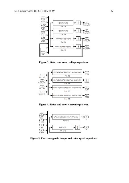
As. J. Energy Env. 2010, 11(01), 48-59 51isαL=ψ− Lψrα sα mα rα,2Ls αLrα − Lmα(9)isβL=ψ− Lψrβ sβ mβ rβ,2LsβLrβ − Lmβ(10)irαL ψ=− Lψsα rα mα sα,2Ls αLrα − Lmα(11)irβL=ψ− Lψsβ rβ mβ sβ.2LsβLrβ − Lmβ(12)The equation <strong>of</strong> electromagnetic torque produced by the machine is then given by the equation:Te = pp( Lmβisβir α−Lm αisαi rβ), (13)and the mechanical <strong>dynamic</strong> is <strong>model</strong>ed by the equationdJ ωr= Te −TL.dt(14)where vs α, vsβ, vr α,vsβare the stator and rotor voltages, is α, isβ, ir α,isβare the stator and rotorcurrents, ψs α, ψsβ, ψr α,ψs βare the stator and rotor flux linkages, Rs α, Rsβ, Rr α,Rsβare the stator androtor resistances, Ls α, Lsβ, Lr α,Lsβare the stator and rotor inductances, Lmα, Lmβare themagnetizing inductances, ω ris the electrical rotor angular speed, T eis the electromagnetictorque, TLis the load torque, J is the rotor moment <strong>of</strong> inertia, d dtand a is the main per auxiliary winding turns ratio.Modelling Using Matlab/Simulinkis the differential operatorMatlab/Simulink <strong>model</strong>s were developed to examine the asymmetrical <strong>two</strong>-<strong>phase</strong> <strong>induction</strong><strong>motor</strong>. The equation from (1)-(4) and (9)-(14) have been implemented in Simulink <strong>using</strong> adifferent block. In this paper the step by step <strong>model</strong>ling <strong>of</strong> the asymmetrical <strong>two</strong>-<strong>phase</strong><strong>induction</strong> <strong>motor</strong> has been described.Figs. 3 and 4 show the subsystem block <strong>of</strong> stator and rotor voltages and currents, respectively.The electromagnetic torque and rotor speed determined is as shown in Fig. 5. Finally in Fig. 6implementation <strong>of</strong> the Simulink <strong>model</strong> <strong>of</strong> asymmetrical <strong>two</strong>-<strong>phase</strong> <strong>induction</strong> <strong>motor</strong> has beenshown.
As. J. Energy Env. 2010, 11(01), 48-59 52Figure 3. Stator and rotor voltage equations.Figure 4. Stator and rotor current equations.Figure 5. Electromagnetic torque and rotor speed equations.
- Page 1 and 2: As. J. Energy Env. 2010, 11(01), 48
- Page 3: As. J. Energy Env. 2010, 11(01), 48
- Page 7 and 8: As. J. Energy Env. 2010, 11(01), 48
- Page 9 and 10: As. J. Energy Env. 2010, 11(01), 48
- Page 11 and 12: As. J. Energy Env. 2010, 11(01), 48