Data Sheet T 8135 EN Valve Series V 2001 Three ... - Rencor Controls
Data Sheet T 8135 EN Valve Series V 2001 Three ... - Rencor Controls
Data Sheet T 8135 EN Valve Series V 2001 Three ... - Rencor Controls

Create successful ePaper yourself
Turn your PDF publications into a flip-book with our unique Google optimized e-Paper software.
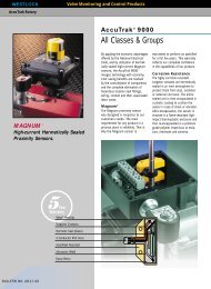
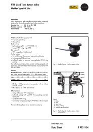
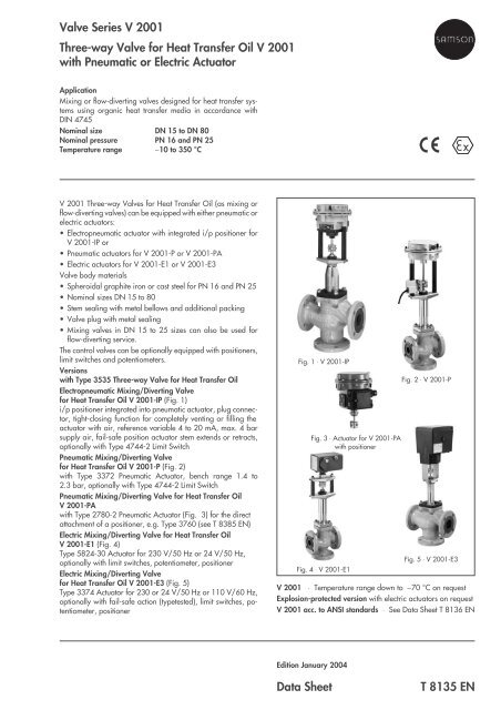
<strong>Valve</strong> <strong>Series</strong> V <strong>2001</strong><strong>Three</strong>-way <strong>Valve</strong> for Heat Transfer Oil V <strong>2001</strong>with Pneumatic or Electric ActuatorApplicationMixing or flow-diverting valves designed for heat transfer systemsusing organic heat transfer media in accordance withDIN 4745Nominal size DN 15 to DN 80Nominal pressure PN 16 and PN 25Temperature range −10 to 350 °CV <strong>2001</strong> <strong>Three</strong>-way <strong>Valve</strong>s for Heat Transfer Oil (as mixing orflow-diverting valves) can be equipped with either pneumatic orelectric actuators:• Electropneumatic actuator with integrated i/p positioner forV <strong>2001</strong>-IP or• Pneumatic actuators for V <strong>2001</strong>-P or V <strong>2001</strong>-PA• Electric actuators for V <strong>2001</strong>-E1 or V <strong>2001</strong>-E3<strong>Valve</strong> body materials• Spheroidal graphite iron or cast steel for PN 16 and PN 25• Nominal sizes DN 15 to 80• Stem sealing with metal bellows and additional packing• <strong>Valve</strong> plug with metal sealing• Mixing valves in DN 15 to 25 sizes can also be used forflow-diverting service.The control valves can be optionally equipped with positioners,limit switches and potentiometers.Versionswith Type 3535 <strong>Three</strong>-way <strong>Valve</strong> for Heat Transfer OilElectropneumatic Mixing/Diverting <strong>Valve</strong>for Heat Transfer Oil V <strong>2001</strong>-IP (Fig. 1)i/p positioner integrated into pneumatic actuator, plug connector,tight-closing function for completely venting or filling theactuator with air, reference variable 4 to 20 mA, max. 4 barsupply air, fail-safe position actuator stem extends or retracts,optionally with Type 4744-2 Limit SwitchPneumatic Mixing/Diverting <strong>Valve</strong>for Heat Transfer Oil V <strong>2001</strong>-P (Fig. 2)with Type 3372 Pneumatic Actuator, bench range 1.4 to2.3 bar, optionally with Type 4744-2 Limit SwitchPneumatic Mixing/Diverting <strong>Valve</strong> for Heat Transfer OilV <strong>2001</strong>-PAwith Type 2780-2 Pneumatic Actuator (Fig. 3) for the directattachment of a positioner, e.g. Type 3760 (see T 8385 <strong>EN</strong>)Electric Mixing/Diverting <strong>Valve</strong> for Heat Transfer OilV <strong>2001</strong>-E1 (Fig. 4)Type 5824-30 Actuator for 230 V/50 Hz or 24 V/50 Hz,optionally with limit switches, potentiometer, positionerElectric Mixing/Diverting <strong>Valve</strong>for Heat Transfer Oil V <strong>2001</strong>-E3 (Fig. 5)Type 3374 Actuator for 230 or 24 V/50 Hz or 110 V/60 Hz,optionally with fail-safe action (typetested), limit switches, potentiometer,positionerFig. 1 ⋅ V <strong>2001</strong>-IPFig. 3 ⋅ Actuator for V <strong>2001</strong>-PAwith positionerFig. 4 ⋅ V <strong>2001</strong>-E1Fig. 2 ⋅ V <strong>2001</strong>-PFig. 5 ⋅ V <strong>2001</strong>-E3V <strong>2001</strong> ⋅ Temperature range down to −70 °C on requestExplosion-protected version with electric actuators on requestV <strong>2001</strong> acc. to ANSI standards ⋅ See <strong>Data</strong> <strong>Sheet</strong> T 8136 <strong>EN</strong>Edition January 2004<strong>Data</strong> <strong>Sheet</strong>T <strong>8135</strong> <strong>EN</strong>
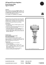
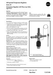
Principle of operationDepending on the version, the three-way valve for heat transferoil can be used for either mixing or flow-diverting service.In mixing valves, the media to be mixed enter at valve ports Aand B. The combined media exit the valve at port AB (Fig. 7).The flow rate from valve port A or B to the common port AB dependson the cross-sectional area between the seats and plugs.Mixing valves in nominal sizes DN 15 to 25 are also suitable forflow-diverting service.In flow-diverting valves, in contrast, the medium enters at valveport AB and the partial flows exit at valve ports A and B (Fig. 6).The plug stem is sealed by a metal bellows and an additionalpacking.Fail-safe position with pneumatic actuatorsDepending on how the springs are arranged in theelectropneumatic or pneumatic actuator, the control valve hastwo different fail-safe positions that become effective when thesupply air fails:Actuator stem extends (FA),In mixing valves, port B is closed when the supply air fails. In divertingvalves, port A is closed.Actuator stem retracts (FE),In mixing valves, port A is closed when the supply air fails. In divertingvalves, port B is closed.Associated documentationRefer to the Mounting and Operating Instructions delivered withthe product:EB <strong>8135</strong>/6 <strong>EN</strong> V <strong>2001</strong> <strong>Three</strong>-way <strong>Valve</strong>EB 8313 <strong>EN</strong> Pneumatic actuator for mixing/divertingvalves V <strong>2001</strong>-IP and V <strong>2001</strong>-PPEB 5840 <strong>EN</strong> Type 2780-2 Actuator for V <strong>2001</strong>-PAEB 5824 <strong>EN</strong> Electric Actuator for V <strong>2001</strong>-E1EB 8331-1 <strong>EN</strong> Electric Actuator for V <strong>2001</strong>-E3AABBFig. 7 ⋅ V <strong>2001</strong>-IP Mixing <strong>Valve</strong> for Heat Transfer Oil,pneumatic actuator with integrated i/p positionerABABFig. 6 ⋅ V <strong>2001</strong> <strong>Three</strong>-way <strong>Valve</strong> for Heat Transfer Oilplug arrangement in flow-diverting valve2 T <strong>8135</strong> <strong>EN</strong>
1. V <strong>2001</strong> <strong>Three</strong>-way <strong>Valve</strong> for Heat Transfer OilTable 1.1 ⋅ Technical dataNominal size DN 15 ⋅ 20 ⋅ 25 ⋅ 32 ⋅ 40 ⋅ 50 ⋅ 65 ⋅ 80Material Spheroidal graphite iron ⋅ <strong>EN</strong>-JS1049 Cast steel ⋅ 1.0619Connection Flanges <strong>EN</strong> 1092-1 Form B1, Ra 3.2 to 12.5 µm ⋅ <strong>EN</strong> 1092-1, groove Form DNominal pressure PN 16 ⋅ 25Seat/plug sealingMetal sealingCharacteristicLinearRangeability30 : 1 up to DN 25 ⋅ 50 : 1 DN 32 or largerTemperature range−10 (−70*) ... 350 °C ⋅ * Extended temperature range down to −70 °C on requestLeakage class acc. toDIN <strong>EN</strong> 1349Metal sealing: I (0.05 % of the K vs value)Table 1.2 ⋅ Materials ⋅ Material number according to DIN <strong>EN</strong>Nominal size DN 15 ⋅ 20 ⋅ 25 ⋅ 32 ⋅ 40 ⋅ 50 ⋅ 65 ⋅ 80<strong>Valve</strong> body Spheroidal graphite iron ⋅ <strong>EN</strong>-JS1049 Cast steel ⋅ 1.0619<strong>Valve</strong> bonnet Cast steel S235JR (St 37)Seat and plug Seat Up to DN 25: 1.4305 ⋅ DN 32 or larger: 1.4104Plug 1.4305Bellows seal 1.4541 ⋅ 1.4301PackingPTFEBody gasketGraphite on metal coreTable 1.3 ⋅ Nominal sizes, K VS values and seat diametersNominal sizes DN 15 20 25 32 40 50 65 80K VS value 4 6.3 8 16 20 32 50 80Seat diameter mm 24 40 65Rated travel mm 15Table 1.4 ⋅ K VS values and associated nominal sizesK VS 4 6.3 8 16 20 32 50 80DN15 •20 •25 •32 •40 •50 •65 •80 •3 T <strong>8135</strong> <strong>EN</strong>
2. Pneumatic actuatorsTable 2.1 ⋅ Technical dataActuatorElectropneumatic actuator forV <strong>2001</strong>-IPPneumatic actuator forV <strong>2001</strong>-PPneumatic actuator forV <strong>2001</strong>-PA 1)Actuator area 120 cm 2 120 cm 2 120 cm 2Fail-safe positionActuator stem extends or retractsReference variable/ Stem extends 4 to 20 mA ⋅ Minimum current 3.6 mA Bench range: 1.4 to 2.3 barbench rangeLoad impedance < 6 V (300 Ω/20 mA)Stem retractsfor fail-safe positionDirection of operation >>, fixedBench range: 1.4 to 2.3 barCharacteristicLinear, deviation from terminal-basedconformity ≤ 2 %Linear, deviation from terminalbasedconformity ≤ 1.5 %Hysteresis ≤ 1 %−≤ 0.5 %Variable position ≤ 7 % −Transit timefor rated travelp perm =4 barApprox. 3 s2 sAir consumption insteady-state condition≤ 160 l n /h at p perm = 4 bar−≤ 100 l n /hsignal pressure 0.6 barDegree of protection IP 54 2) − IP 54 2)Perm. ambient temperature −30 to +70 °C −35 to +90 °C −20 to +70 °CAccessories 1 or 2 limit switches with selector switch (IP 65, Ex d, supply lead 3 m)Inductive limit switchnominal voltage/current: 250 V~/5 A~ or 250 V-/0.4 A-1) <strong>Data</strong> apply in conjunction with Type 3760 Positioner, see <strong>Data</strong> <strong>Sheet</strong> T 8385 <strong>EN</strong>.2) IP 65 as special version with filter check valve (order no. 1790-7408)Table 2.2 ⋅ Materials ⋅ Material number according to DIN <strong>EN</strong>Actuator case GD-Al Si 12DiaphragmNBRActuator stem 1.4305Positioner housing POM-GF − PolyamideYoke Stem 9SMn28K galvanized, mat black finishBracket 1.4301−Table 2.3 ⋅ Permissible differential pressures for plug with metal sealing, all pressures in barFail-safe position Actuator stem extends Actuator stem retractsBench range bar 1.4 to 2.3 1.4 to 2.3Min./max. supply pressure bar 3.7 to 4.0 3.7 to 4.0K VS values∆p when p 2 = 0 bar1.6 to 8 16 − − 16 − −16 to 32 − 10 − − 10 −50 ⋅ 80 − − 3.5 − − 3.54 T <strong>8135</strong> <strong>EN</strong>
3. Electric actuatorsTable 3.1 ⋅ Technical dataActuator for V <strong>2001</strong>-E1 V <strong>2001</strong>-E3Nominal thrust2.5 kN0.7 kNType 3374-11Transit time for rated travel 90 s 120 s ⋅ Other transit times on requestPower supply 230, 24 V/50 Hz • •110 V/60 Hz − •Power consumption Motor 3 VA 7.5 VAWith positioner − 9.5 VAManual override • •Degree of protection IP 54 when vertically mounted IP 54 ⋅ IP 65 with cable glandMounting position Suspended mounting position not permitted (see EB 5824 <strong>EN</strong> and EB 8331-1 <strong>EN</strong>)Perm. ambient temperature 0 to 50 °C 5 to 60 °CAdditional electrical equipmentLimit switch 2 2Potentiometer(not for version with positioner)10 to 1000 Ω20 to 1000 ΩPositioner Analog DigitalControl signal4(0) to 20 mA ⋅ 0(2) to 10 VTable 3.2 ⋅ Permissible differential pressure for plug with metal sealing, all pressures in barActuator for V <strong>2001</strong>-E1 V <strong>2001</strong>-E3Nominal thrust 0.7 kN 1.8 kNK VS value∆p when p 2 = 0 bar1.6 to 8 10 1616 to 32 3.5 1250 ⋅ 80 − 45 T <strong>8135</strong> <strong>EN</strong>
4. Dimensions in mm and weights in kg ⋅ V <strong>2001</strong> <strong>Three</strong>-way <strong>Valve</strong> for Heat Transfer OilNominal size DN 15 20 25 32 40 50 65 80Table 4.1 ⋅ V <strong>2001</strong>-IP Electropneumatic Control <strong>Valve</strong> ⋅ Dimensions for fail-safe position actuator stem extends or retractsL (Installation length) mm 130 150 160 180 200 230 290 310Installation heightH1 (stem extends) mm 471 481 586H1 (stem retracts) mm 382 386 671H2 mm 70 80 85 100 105 120 130 140H3 (stem extends) mm 110 110 110H3 (stem retracts) mm 210 210 210Weight kg 8.7 9.2 10.2 16.7 17.2 19.7 30.7 35.7Table 4.2 ⋅ V <strong>2001</strong>-P Pneumatic Control <strong>Valve</strong> ⋅ Dimensions valid for both fail-safe positionsL (Installation length) mm 130 150 160 180 200 230 290 310Installation heightH1 mm 471 481 586H2 mm 70 80 85 100 105 120 130 140H3 (minimum distance) mm 110 110 110Weight 8.3 8.8 9.8 16.3 16.8 19.3 30.3 35.3Table 4.3 ⋅ V <strong>2001</strong>-PA Pneumatic Control <strong>Valve</strong> ⋅ Dimensions valid for both fail-safe positionsL (Installation length) mm 130 150 160 180 200 230 290 310Installation heightH1 mm 524 534 639H2 mm 40 72 100H3 (minimum distance) mm 110 110 110Weight kg 8.3 9.3 10.6 15.3 15.9 18.8 26.3 32.1Table 4.4 ⋅ V <strong>2001</strong>-E1 Electric Control <strong>Valve</strong>L (Installation length) mm 130 150 160 180 200 230 −Installation heightH1 mm 429 439H2 mm 70 80 85 100 105 120H3 (minimum distance) mm 110 110−Weight kg 6.8 7.3 8.3 14.8 15.3 17.8Table 4.5 ⋅ V <strong>2001</strong>-E3 Electric Control <strong>Valve</strong>L (Installation length) mm 130 150 160 180 200 230 290 310Installation heightH1 mm 529 539 644H2 mm 70 80 85 100 105 120 130 140H3 1) (minimum distance) mm 110 110 110Weight kg 10.5 11 12 18.5 19 21.5 32.5 37.51) Note: Bonnet bolts are inserted from the top.6 T <strong>8135</strong> <strong>EN</strong>
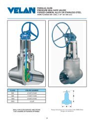
Dimensional diagrams and terminal connectionsPG 11Ø168H3123231Ø168H3PG 11GØ168H3145 H3H1H1H1H11 - Press. gauge G 1/ 82 - Supply air G 1/ 43 - Venting G 1/ 4LH2V <strong>2001</strong>-IP, valve CLOSEDH2H2LLLV <strong>2001</strong>-IP, valve OP<strong>EN</strong> V <strong>2001</strong>-P V <strong>2001</strong>-PAH2145 H33-stepOutput Inputsignal0...10V 0...10V 24V~N+ – – +0...20mA– +NeLaL 32 33 12 11 13 N LH1StemretractseLPositioner IIextendsaL41 44 42 51 54 5263 62 6182 83H2LV <strong>2001</strong>-E1SwitchPotentiometerPriority circuit(optional withpositioner)60193H3LCeCe3-step signal– + N N LOptions:Limit switchPotentiometer(not for version with positioner)41 44 42 51 54 52 81 82 83 91 92 93aL eL N N LH1** Magnet for versionwith fail-safe positionTerminal connections for version with positionerV mA+ _mA ++ _V V++ _+ V_LNH2LV <strong>2001</strong>-E331 32 33 13 12 11 81 82 83 84 L NPos. transmitter Input Binary input Binary output Power supply7 T <strong>8135</strong> <strong>EN</strong>
5. Ordering textWhen ordering, please indicate the following details:V <strong>2001</strong> <strong>Three</strong>-way <strong>Valve</strong> for Heat Transfer OilMixing orflow-diverting valveNominal size and flow rate DN .... K VS ....Nominal pressure PN ....Body materialSpheroidal graphiteiron or cast steelSeat/plug sealingMetal sealingActuatorsfor V <strong>2001</strong>-IP: Electropneumatic actuatorwith integrated positioner4 to 20 mAoptionallyIntrinsically safe II 2 G EEx ia IIC T6 acc. to ATEXAccessoriesLimit switches 1 or 2for V <strong>2001</strong>-P: Pneumatic actuatorFail-safe position: Actuator stem extends orretractsBench range1.4 to 2.3 barAccessoriesLimit switches 1 or 2for V <strong>2001</strong>-PA: Pneumatic actuator for the direct attachmentof a positioner, e.g. Type 3760 (see Fig. 3)Fail-safe position: Actuator stem extends orretractsBench range1.4 to 2.3 barfor V <strong>2001</strong>-E1: Electric actuatorPower supply230 V/50 Hz or24 V/50 HzAccessoriesLimit switches 2Potentiometer0 to 1000 ΩPositioner input4(0) to 20 mA or0(2) to 10 Vfor V <strong>2001</strong>-E3: Electric actuatorNominal thrust(only w/o fail-safe action)Power supply2.5 kN230 V/50 Hz24 V/50 Hz110 V/60 HzAccessoriesLimit switches 2Potentiometer0 to 1000 ΩDigital positionerInput and output4(0) to 20 mA or0(2) to 10 VSpecifications subject to change without notice.SAMSON AG ⋅ MESS- und REGELTECHNIKWeismüllerstraße 3 ⋅ 60314 Frankfurt am Main ⋅ GermanyPhone +49 69 4009-0 ⋅ Fax +49 69 4009-1507Internet: http://www.samson.deT <strong>8135</strong> <strong>EN</strong>