
Create successful ePaper yourself
Turn your PDF publications into a flip-book with our unique Google optimized e-Paper software.
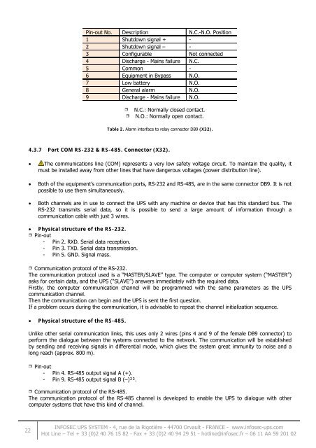
Pin-out No. Description N.C.-N.O. Position1 Shutdown signal + -2 Shutdown signal – -3 Configurable Not connected4 Discharge - Mains failure N.C.5 Common -6 Equipment in Bypass N.O.7 Low battery N.O.8 General alarm N.O.9 Discharge - Mains failure N.O.N.C.: Normally closed contact.N.O.: Normally open contact.Table 2. Alarm interface to relay connector DB9 (X32).4.3.7 Port COM RS-232 & RS-485. Connector (X32).The communications line (COM) represents a very low safety voltage circuit. To maintain the quality, itmust be installed away from other lines that have dangerous voltages (power distribution line).Both of the equipment’s communication ports, RS-232 and RS-485, are in the same connector DB9. It is notpossible to use them simultaneously.Both channels are in use to connect the UPS with any machine or device that has this standard bus. TheRS-232 transmits serial data, so it is possible to send a large amount of information through acommunication cable with just 3 wires.Physical structure of the RS-232.Pin-out- Pin 2. RXD. Serial data reception.- Pin 3. TXD. Serial data transmission.- Pin 5. GND. Signal mass.Communication protocol of the RS-232.The communication protocol used is a “MASTER/SLAVE” type. The computer or computer system (“MASTER”)asks for certain data, and the UPS (“SLAVE”) answers immediately with the required data.Firstly, the computer communication channel will be programmed with the same parameters as the UPScommunication channel.Then the communication can begin and the UPS is sent the first question.If a problem occurs during the communication, it is advisable to repeat the channel initialization sequence.Physical structure of the RS-485.Unlike other serial communication links, this uses only 2 wires (pins 4 and 9 of the female DB9 connector) toperform the dialogue between the systems connected to the network. The communication will be establishedby sending and receiving signals in differential mode, which gives the system great immunity to noise and along reach (approx. 800 m).Pin-out- Pin 4. RS-485 output signal A (+).- Pin 9. RS-485 output signal B (–)²².Communication protocol of the RS-485.The communication protocol of the RS-485 channel is developed to enable the UPS to dialogue with othercomputer systems that have this kind of channel.22INFOSEC UPS SYSTEM - 4, rue de la Rigotière - 44700 Orvault - FRANCE - www.infosec-ups.comHot Line – Tel + 33 (0)2 40 76 15 82 - Fax + 33 (0)2 40 94 29 51 - hotline@infosec.fr – 06 11 AA 59 201 02