RF Design of the Re-buncher Cavities for the LIPAC ... - CERN
RF Design of the Re-buncher Cavities for the LIPAC ... - CERN
RF Design of the Re-buncher Cavities for the LIPAC ... - CERN

Create successful ePaper yourself
Turn your PDF publications into a flip-book with our unique Google optimized e-Paper software.
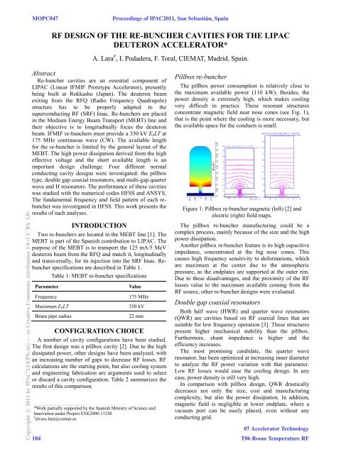
MOPC047Proceedings <strong>of</strong> IPAC2011, San Sebastián, Spain<strong>RF</strong> DESIG OF THE RE-BUCHER CAVITIES FOR THE<strong>LIPAC</strong>DEUTERO ACCELERATOR*A. Lara # , I. Podadera, F. Toral, CIEMAT, Madrid, Spain.Copyright c○ 2011 by IPAC’11/EPS-AG — cc Creative Commons Attribution 3.0 (CC BY 3.0)Abstract<strong>Re</strong>-<strong>buncher</strong> cavities are an essential component <strong>of</strong><strong>LIPAC</strong> (Linear IFMIF Prototype Accelerator), presentlybeing built at Rokkasho (Japan). The deuteron beamexiting from <strong>the</strong> <strong>RF</strong>Q (Radio FrequencyQuadrupole)structure has to be properly adapted to <strong>the</strong>superconducting <strong>RF</strong> (S<strong>RF</strong>) linac. <strong>Re</strong>-<strong>buncher</strong>s are placedin <strong>the</strong> Medium Energy Beam Transport (MEBT) line and<strong>the</strong>ir objective is to longitudinally focus <strong>the</strong> deuteronbeam. IFMIF re-<strong>buncher</strong>s must provide a 350 kV E 0 LT at175 MHz continuous wave (CW). The available length<strong>for</strong> <strong>the</strong> re-<strong>buncher</strong> is limited by <strong>the</strong> generallayout <strong>of</strong> <strong>the</strong>MEBT. The high power dissipation derived from <strong>the</strong> higheffective voltage and <strong>the</strong> short available length is animportant design challenge. Four different normalconducting cavity designs were investigated: <strong>the</strong> pillboxtype, double gap coaxial resonators, and multi-gap quarterwave and H resonators. The per<strong>for</strong>mance <strong>of</strong><strong>the</strong>se cavitieswas studied with <strong>the</strong> numerical codes HFSSS and ANSYS.The fundamental frequency and field pattern <strong>of</strong> each re-presents <strong>the</strong><strong>buncher</strong> was investigated in HFSS. This workresults <strong>of</strong> such analyses.ITRODUCTIOTwo re-<strong>buncher</strong>s are located in <strong>the</strong> MEBTline [1]. TheMEBT is part <strong>of</strong> <strong>the</strong> Spanish contribution to<strong>LIPAC</strong>. Thepurpose <strong>of</strong> <strong>the</strong> MEBT is to transport <strong>the</strong> 125 mA/5 MeVdeuteron beam from <strong>the</strong> <strong>RF</strong>Q and match it, longitudinallyand transversally, <strong>for</strong> its injection into <strong>the</strong> S<strong>RF</strong> linac. <strong>Re</strong>-<strong>buncher</strong> specifications are described in Table1.Table 1: MEBT re-<strong>buncher</strong> specificationsParameterValueFrequency 175 MHzMaximum E 0 LT 350 kVBeam pipe radius 22 mmCOFIGURATIO CHOICEA number <strong>of</strong> cavity configurations have been studied.The first design was a pillbox cavity [2]. Due to <strong>the</strong> highdissipated power, o<strong>the</strong>r designs have been analysed, withan increasing number <strong>of</strong> gaps to decrease <strong>RF</strong> losses. <strong>RF</strong>calculations are <strong>the</strong> starting point, but also cooling systemand engineering fabrication are arguments used to selector discard a cavity configuration. Table 2 summarizes <strong>the</strong>results <strong>of</strong> this comparison.___________________________________________*Work partially supported by <strong>the</strong> Spanish Ministry <strong>of</strong> Science andInnovation under Project ENE2009-11230# alvaro.lara@ciemat.es184Pillbox re-<strong>buncher</strong>The pillbox power consumption isrelatively close to<strong>the</strong> maximum available power (110kW). Besides, <strong>the</strong>power density is extremely high, which makes coolingvery difficult in practice. These resonant structuresconcentrate magnetic field near nosecones (see Fig. 1),that is <strong>the</strong> point where <strong>the</strong> cooling is more necessary, but<strong>the</strong> available space <strong>for</strong> <strong>the</strong> conducts issmall.Figure 1: Pillbox re-<strong>buncher</strong> magnetic (left) [2] andelectric (right) field maps.The pillbox re-<strong>buncher</strong> manufacturing could be acomplex process, mainly because <strong>of</strong> <strong>the</strong> size and <strong>the</strong> highpower dissipation.Ano<strong>the</strong>r pillbox re-<strong>buncher</strong> feature is its high capacitiveimpedance, concentrated at <strong>the</strong> bignose cones. Thiscauses high frequency sensitivity to de<strong>for</strong>mations, whichare maximum at <strong>the</strong> center due to <strong>the</strong> atmosphericpressure, as <strong>the</strong> endplates are supported at <strong>the</strong> outer rim.Due to <strong>the</strong>se disadvantages, and <strong>the</strong> proximity <strong>of</strong> <strong>the</strong> <strong>RF</strong>losses value to <strong>the</strong> maximum available coming from <strong>the</strong><strong>RF</strong> source, o<strong>the</strong>r re-<strong>buncher</strong> designs were evaluated.Double gap coaxial resonatorsBoth half wave (HWR) and quarter wave resonators(QWR) are cavities based on <strong>RF</strong> coaxial lines that aresuitable <strong>for</strong> low frequency operation [3]. These structurespresent higher mechanical stabilitythan <strong>the</strong> pillbox.Fur<strong>the</strong>rmore, shunt impedance ishigher and <strong>the</strong>efficiency increases.The most promising candidate, <strong>the</strong> quarter waveresonator, has been optimized at increasing inner diameterto analyze <strong>the</strong> <strong>RF</strong> power variation with that parameter.Low <strong>RF</strong> losses would ease <strong>the</strong> cooling design. In anycase, power density is still very high.In comparison with pillbox design, QWR drasticallydecreases not only <strong>the</strong> size, cost and manufacturingcomplexity, but also <strong>the</strong> power dissipation. In addition,magnetic field is negligible at lower endplate, where avacuum port can be easily placed,even without anyconducting grid.07 Accelerator TechnologyT06 Room Temperature <strong>RF</strong>
Proceedings <strong>of</strong> IPAC2011, San Sebastián, SpainMOPC047Table 2: Comparison results <strong>of</strong> <strong>the</strong> <strong>RF</strong>re-<strong>buncher</strong> cavities studied <strong>for</strong> <strong>LIPAC</strong> (all in copper).Configuration Pillbox HWR QWR 3-GAP QWR 4-GAP QWR 4-GAP IH5-GAP IH UnitsVacuum length (beam axis) 200 240 240 280 280 280Vacuum height 860 876 507 495 495 504Total power 75 41.7 25.8 12.2 9.4 8.5Central stem power - 30.5 18 4.0 1.7 2.2Side stem power - - - - 1990 1447Q 24279 11347 10773 11413 10148 11570E peak 24.3 20 20.6 21.0 14.8 16.0Power density peak 30.3 42 97.4 17.0 13.1 12.0Shunt impedance 0.82 1.46 2.36 4.99 6.51 7.19The HWR power consumption is higher than QWRone, but <strong>the</strong> cooling system design would be easierbecause its stem geometry allows a direct cooling channelgoing across <strong>the</strong> re-<strong>buncher</strong>. Never<strong>the</strong>less, <strong>the</strong> HWR stemcomplicates <strong>the</strong> location <strong>of</strong> a vacuum port. In addition,HWR height is double than QWR one, and <strong>RF</strong> losses are50% higher.The QWR design decreases power consumptioncompared with <strong>the</strong> pillbox and HWR cavities, but someimportant issues should be taken into account: Steering effects: <strong>the</strong>re is an asymmetry in <strong>the</strong>field maps due to <strong>the</strong> drift tube position. Multipactoring inherent to coaxial resonators.In order to relax <strong>the</strong>se issues, it can be concluded that<strong>the</strong> study <strong>of</strong> coaxial resonators with increasing number <strong>of</strong>gaps is a very interesting strategy. One expects that bothpower consumption and power density can be fur<strong>the</strong>rdecreased, while <strong>the</strong> a<strong>for</strong>ementioned drawbacks do notincrease.Multi-gap resonatorsThree to five gap resonators are studied inthis section:3 and 4-gap ones are depicted in Fig. 2, while <strong>the</strong> five gapone is shown in Fig. 3. A significant decrease <strong>of</strong> <strong>RF</strong>losses and peak electric field is achieved with eachadditional gap. The available length is too small toallocate a 5-gap cavity, but due to <strong>the</strong> significant benefits,<strong>the</strong> MEBT layout has been changed, ncreasing thatlength up to 350 mm. The stem cooling is much easier in<strong>the</strong> 5-gap design, which clearly compensates <strong>the</strong> higherfabrication cost.Figure 2: 3 and 4 gap resonators: 3-gap QWR(left), 4-gapQWR (middle), and 4-gap IH (right).07 Accelerator TechnologyOn <strong>the</strong> o<strong>the</strong>r side, <strong>RF</strong> per<strong>for</strong>mancee (shunt impedance)<strong>of</strong> IH type is better than QWR one. The de<strong>for</strong>mationunder atmospheric pressure will behigher in <strong>the</strong> IHmodel, but acceptable with steel endplates.Multipactoring will happen mainly in regular orsymmetric geometries, <strong>the</strong>re<strong>for</strong>e QWR will be moreprone to problems. Finally, an additional advantage isenvisaged, as due to <strong>the</strong> lower required power, bothcooling system and <strong>RF</strong> source requirements are relaxed.In short, it is reasonable to choose <strong>the</strong> 5-gap IH cavityas <strong>the</strong> best candidate <strong>for</strong> <strong>LIPAC</strong> re<strong>buncher</strong>s.DETAILED DESIGThe next step is <strong>the</strong> detailed design <strong>of</strong> <strong>the</strong> 5-gap IHcavity. A full model, including <strong>the</strong> fillet radii necessary<strong>for</strong> <strong>the</strong> fabrication (milling tools) and<strong>the</strong> recesses <strong>for</strong> <strong>the</strong>stem bases, has been studied. Two CF100 pumping portsare drilled on <strong>the</strong> side wall.High order modesFigure 3: 5-gaps IH cavity.320 mm460 mm6.6 kW1.2 kW678 W11746 --13.9 MV/m8.9 W/cm29.29 MΩPerturbations due to high orderr modes in a lowfrequency linac are usually moderate. However, due to<strong>the</strong> high beam power, <strong>the</strong> allowed beam losses are verysmall, and high order modes have been analysed. Table 3T06 Room Temperature <strong>RF</strong> 185Copyright c○ 2011 by IPAC’11/EPS-AG — cc Creative Commons Attribution 3.0 (CC BY 3.0)
MOPC047Proceedings <strong>of</strong> IPAC2011, San Sebastián, Spainshows <strong>the</strong> results. None <strong>of</strong> <strong>the</strong> modes is dangerous <strong>for</strong> <strong>the</strong>beam.Table 3: High order modesOrderFrequency(MHz)Q Type earestbunchfrequency1 175.16 11284 2 238.12 9536 1753 285.08 10229 350Copyright c○ 2011 by IPAC’11/EPS-AG — cc Creative Commons Attribution 3.0 (CC BY 3.0)4 329.04 13699 3505 486.62 33422 0 5256 602.88 33089 TE 11 -like 5257 698.23 32825 +stems 7008 720.39 21412 +stems 7009 777.43 16972 +stems 700CouplerThe coupler will be a loop, that is, <strong>of</strong> magnetic type.The design is based on <strong>the</strong> Spiral-2 re<strong>buncher</strong> coupler [4].A transition will adapt <strong>the</strong> size <strong>of</strong> <strong>the</strong> coaxial line comingfrom <strong>the</strong> <strong>RF</strong> source to <strong>the</strong> input port <strong>of</strong> <strong>the</strong> coupler. Aceramic window will keep <strong>the</strong> vacuum tightness. Beyond<strong>the</strong> ceramic, <strong>the</strong> coaxial line diameter is decreasedsmoothly while keeping 50-ohm characteristicimpedance. The inner conductor will be internally watercooled. The magnetic coupler has been placed closed to<strong>the</strong> stems, where <strong>the</strong> magnetic field is stronger <strong>for</strong> a goodcoupling, while <strong>the</strong> field perturbation is far away from <strong>the</strong>beam axis. The impedance matching is properly achieved:S 11 is -29.8 dB.Figure 4: 5-gaps IH coupler: Spiral-2 model from [4].TunerOnly a magnetic-type tuner is considered. A capacitiveplunger is not a convenient solution, because it should beplaced at <strong>the</strong> medium plane: it would be very long,dissipate a significant power and interfere with <strong>the</strong>pumping ports. There are two plungers, one is manuallydriven, to compensate frequency mismatch due t<strong>of</strong>abrication errors (cold tuning), and <strong>the</strong> o<strong>the</strong>r one ispowered by a stepping motor controlled from <strong>the</strong> LL<strong>RF</strong>system. The motorized tuner shall compensate frequencyvariation in <strong>the</strong> order <strong>of</strong> few per mil <strong>of</strong> <strong>the</strong> nominalfrequency.186Figure 5: Magnetic field distribution on <strong>the</strong> tuner.Symmetric inductive plungers have been modeled ascylinders (see Fig. 5). The tuner size depends on <strong>the</strong>magnetic field at <strong>the</strong> plunger position. There<strong>for</strong>e, it is agood practice to place <strong>the</strong>m near <strong>the</strong> stems, but not toclose, to avoid excessive heating. The overall <strong>RF</strong> losses <strong>of</strong><strong>the</strong> cavity increase about 3% when both plungers areinserted at maximum depth.Manufacturing considerationsThe simplest manufacturing approach is to use stainlesssteel with copper plating <strong>for</strong> <strong>the</strong> wall and endplates. Thestems and <strong>the</strong> drift tubes will be machined from bulk OFEcopper. The stems will be cooled with concentric circuits:cold water inside and warm water outside. The drift tubeswill have not internal cooling conduits. The endplates willbe cooled only in front <strong>of</strong> <strong>the</strong> stems.COCLUSIOThis paper has shown <strong>the</strong> comparison between differentcavity configurations to be used as <strong>LIPAC</strong> re-<strong>buncher</strong>.The five gap IH resonator structure is <strong>the</strong> most efficientstructure. Tuner and coupler will be <strong>of</strong> magnetic type.ACKOWLEDGEMETSSpecial thanks <strong>for</strong> fruitful discussions and advices to M.di Giacomo (GANIL), M. Vretenar (<strong>CERN</strong>), A. Facco(INFN), A. Mosnier (CEA) and A. Schempp (FrankfurtUniversity).REFERECES[1] I. Podadera et al., “The Medium Energy BeamTransport Line (MEBT) <strong>of</strong> <strong>LIPAC</strong>”, <strong>the</strong>se proceedings.[2] M. Desmons and P-Y. Beauvais, “Preliminary studies<strong>of</strong> <strong>the</strong> IFMIF/EVEDA matching section <strong>buncher</strong>”,CEA/Saclay Internal <strong>Re</strong>port, 2008[3] A. Facco, “Low and Intermediate-β Cavity <strong>Design</strong>”,S<strong>RF</strong>09 - Dresden, 17/9/ 2009.[4] M. di Giacomo et al. “<strong>Design</strong> <strong>of</strong> <strong>the</strong> MEBT<strong>Re</strong><strong>buncher</strong>s <strong>for</strong> <strong>the</strong> SPIRAL2 Driver”, Proceedings <strong>of</strong>LINAC08, Victoria, BC, Canada.07 Accelerator TechnologyT06 Room Temperature <strong>RF</strong>