FT-950 - Radiotrans
FT-950 - Radiotrans
FT-950 - Radiotrans
- No tags were found...

You also want an ePaper? Increase the reach of your titles
YUMPU automatically turns print PDFs into web optimized ePapers that Google loves.
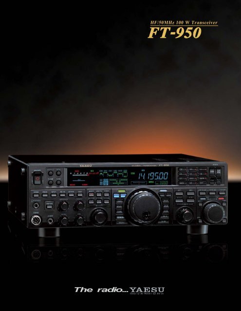
HF/50MHz 100 W Transceiver<strong>FT</strong>-<strong>950</strong>
Yaesu again brings you innovation, quality, functions and featuresthat you will find nowhere else!The <strong>FT</strong>-<strong>950</strong> is the newest radio in the direct lineage of the <strong>FT</strong> DX 9000 and <strong>FT</strong>-2000 series radios.It has been developed to fit the needs of both casual and serious DX enthusiastsas well as new HF licensees eagerly seeking to discover the magic of the HF and 50 MHz bands.Triple-conversion super-heterodyne receive architecture uses 69.450 MHz 1st IF,with powerful 1st IF 3 kHz/6 kHz/15 kHz selectable roofing filters (MCF). You will enjoythe advanced technology of the multi-function 30 kHz 32-bit Floating Point IF DSP.Add the optional DMU-2000 Data Management Unit that provides an array of display capabilities,and include the optional, ultra-sharp, fully-automatic, RF µ -Tuning Preselector System.You may customize your <strong>FT</strong>-<strong>950</strong> with the same great options that are availablewith the <strong>FT</strong> DX 9000 and <strong>FT</strong>-2000 Series Transceivers!The DXer's Choice : <strong>FT</strong>-<strong>950</strong>
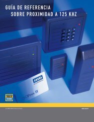
HF/50MHz 100 W TransceiverF T-<strong>950</strong>High-speed Direct Digital Synthesizer (DDS) and High-spec Digital PLLfor Outstanding Local Oscillator PerformanceFactory installed selectable 1st IF 3, 6, & 15 kHz Roofing FiltersTriple-Conversion Receiver Design using 69.450 MHz 1st IFUltra-strong Receiver Front End Includes 8 Bandpass FiltersBuilt-in TCXO for State-of-Art Stability (0.5 ppm @ room temperature)Advanced Multi-function 30 kHz 32-bit Floating Point IF DSPIF WIDTH, IF SHI<strong>FT</strong>, NOTCH, and CONTOUR FeaturesActual Size2
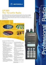
High-performance Receiver Design inherited from the proud lineage of the <strong>FT</strong> DX 9000/<strong>FT</strong>-2000 Series radiosTriple-conversion Receiver Design with Optimized Stage BalanceThe triple-conversion design features a 1st IF of 69.45 MHz, a 2nd IF of450 kHz, and a 3rd IF of 30 kHz (FM: 24 kHz). Each stage's advancedfiltering protects the stages that follow from unwanted signal voltage, creatinga quiet, robust receiver with unmatched total system performance.Robust Receiver Front EndThe RF amplifier stage is designed for low and high intercept. Twostrong series-connected 2SC3356 bipolar transistors with negativefeedback assure consistent, repeatable performance. The low noisefigure and carefully controlled stage gains ensure that only the preciseamount of gain needed is actually utilized. The front panel "IPO"switch lets you select direct feed to the first mixer (IPO), Preamp 1 (RFAMP1), or Preamp 2 (RF AMP2) which adds a second preamplifierstage in series. Adapt the RF front end according to the antenna in useand the noise and interference conditions present at the time.IPO (Intercept Point Optimization)allows you to set the total front-endgain to optimize RF stage performance. The ultra-strong first mixer ofthe <strong>FT</strong>-<strong>950</strong> features SPM5001 FETs in an active, doubly-balancedconfiguration optimized for a severe multi-signal environment. Theactive design results in no net loss of gain in the mixer circuit itself,thus eliminating the need for pre-amplification and permitting directfeed of received signals to the first mixer.ABANTENNASELECTORATTOPTIONµ-TUNEReceiver Block DiagramFront EndBPFIPO "ON"RFAMP1RFAMP2IF1st IF 2nd IF 3rd IF (DSP)69.450 MHz 450 kHz30 kHzDSPROOFINGAGCFILTERDET1stIF AMPCF3rdIF AMP ADC3 k/6 k/15 k1st Local2nd Local 3rd LocalFILTER AGC DETDACFactory installed 1st IF Roofing FiltersThe 69.450 first IF stage features three roofing filters (15 kHz, 6 kHz, and3 kHz)automatically selected by mode for best performance on today'smost crowded bands. Each roofing filter is a four-pole, fundamental-modemonolithic crystal filter design to produce excellent shape factor.Under busy band conditions, the roofing filters are positioned right afterthe first mixer of the <strong>FT</strong>-<strong>950</strong>, and significantly improve the 3rd-OrderIntercept Point performance for all stages that follow.3 roofing filters (15 kHz, 6 kHz, and 3 kHz)Log10 dB/RBW10 kHzVBW10 kHz3 kHz Roofing Filter Performance Local DesignREF -14.0 dBm ATT 00 dBBlock DiagramSWP 50 msSPAN 500 kHzCENTER 69.450 MHz10dB/Div · 50 kHz/DivThe IF Digital Signal Processing system of the <strong>FT</strong>-<strong>950</strong> is based on the TITMS320C6713 32-bit floating point DSP IC. Select the best DSP functionby simply rotating the SELECT dial located to the left side of the main dial.World-renowned variable IF WIDTH and IF SHI<strong>FT</strong>interference reduction SystemsWhile leaving the pitch of the incoming signal and bandwidth of the IFpassband unchanged, the IF Shift system allows you to vary the actualpassband higher or lower in frequency, eliminating interference that youencounter outside the passband. You can also improve your reception bychoosing to narrow the bandwidth of the IF WIDTH function and thenvarying the passband with the IF SHI<strong>FT</strong> by selecting these settings withthe SELECT dial. (The IF SHI<strong>FT</strong> control is concentric with the IFWIDTH control.)The variable IF WIDTH system has a default centerbandwidth of 2.4 kHz for SSB and CW, and 500 Hz for RTTY and PSKHigh-speed Direct Digital Synthesizer (DDS)Digital PLL for Outstanding Local Oscillator PerformanceAn ultra-low-noise local oscillator system that produces a very cleanfirst IF signal is essential to improve the strong-signal-handlingcapabilities of the receiver section, in a multi-signal environment. Thespurious-free dynamic range and close-in blocking performance aresubstantially enhanced with the high Carrier-to-Noise (C/N)ratio ofthe <strong>FT</strong>-<strong>950</strong> high-speed digital PLL.TCXODDSX2DDSPLLVCOVCOVCOVCOLPFLPFAMP1/4Devide2nd Local3rd LocalLPF1stLocalCarrier-to-Noise (C/N) CharacteristicsThe legendary Yaesu 32-bit floating point IF DSP - legendary known and reputed among the serious DXersand enthusiasts - will give you the edge over all other DSP-based radiosoperation. By simply rotating the IF WIDTH control counterclockwise,the passband may be reduced to as little as 500 Hz (or 1.8 kHz on SSB).If you like to listen in a wider bandwidth for greater fidelity on SSB, theSSB bandwidth may be expanded to 3000 Hz to possibly improve theaudio-quality of the station you are working. And for improved AMBroadcast reception, you may use the one-touch NAR function to togglebetween 9 kHz (wide)and 6 kHz IF WIDTH functionStandard Passband(narrow), depending on interference,for better audio. While the IF WIDTHModified Passbandis generally used for setting the IFDSP bandwidths, you may also utilizeMin 200 Hz/25 Hzthe one-touch NAR (Narrow)functionMid 2.4 kHz/500 HzMax 3 kHz/2.4 kHzto reduce the passband further to yourpre-selected center bandwidth (SSB:IF SHI<strong>FT</strong> functionselections available from 200/400/600/Standard Passband850/1100/1350/1500/1650/1800 Hz CW:Modified Passbandselections available from 100/200/ 300/400/500 Hz, Factory preset default :1800 Hz/SSB, 500 Hz/CW, 300 Hz/RTTY20 Hz Step ±1kHzand PSK).WIDTH USB/LSB CW,RTTY,PKT AM FM,PKT(FM)WIDE (Max) 3 kHz 2.4 kHz - -WIDE/Default 2.4 kHz 500 Hz 9 kHz 15 kHzWIDE (Min) 1.8 kHz 2.4 kHz(CW)/500 Hz (RTTY,PKT) - -NAR/Default 1.8 kHz 500 Hz(CW)/300 Hz 6 kHz 9 kHzNAR (Min) 200 Hz 100 Hz - -3
CONTOUR Control function with natural analog feelThe incredibly sharp "brick wall" filters of the IF DSP system can revealcharacteristics of incoming signals that you have never heard before,and not all of them are really pleasant to listen to all the time.Using theCONTOUR control, you can roll off low-frequency or high-frequencycomponents to shape the receiver passband differently, or null out partof the mid-range area.With continuous adjustment throughout thepassband, you may null out interfering or irrelevant frequency components.The desired frequency components will significantly rise out of thebackground noise, improving fidelity and signal-to-noise (S/N) ratio.Manual IF Notch and Beat-reducingAutomatic Digital Notch Filter (DNF)Selecting the NOTCH function with the SELECT dial will enable the<strong>FT</strong>-<strong>950</strong>'s very high "Q" IF Notch Filter, producing a deep notching effecttypically in excess of 70 dB.Using the Menu mode to choose the "digital"NOTCH function, a uniquely designed DSP Auto Notch (DNF) filtercan also be engaged.Independently from the "manual" Notch function,the Auto Notch (DNF) can reduce multiple carriers within the passband.DSP Digital Noise ReductionFor reduction of random noise types, the <strong>FT</strong>-<strong>950</strong> utilizes a powerfulDigital Noise Reduction filter, that contains fifteen different noiseanalysis parameters specially created after thousands of hours of onthe-airtesting.You may choose any of these parameters to effectivelyreduce most noise under nearly any given conditions.Analog-sounding High-quality Digital SSBModulationThe YAESU DSP digital modulation technique not only provides ananalog-sounding high-quality digital SSB modulation envelope, butalso allows the transmission bandwidth to be adjusted by the operator.CONTOUR Filter Conceptual DiagramIF NOTCH PerformancePMFIR Log Magnitude100-10-20-30-40-50-60-70-80-90-100FREQUENCY kHzDigital Noise Reduction PerformanceMKR(250):1.555kHzA MAGOUTPUTSTART:10HzThe Secret of the <strong>FT</strong> DX 9000/<strong>FT</strong>-2000/<strong>FT</strong>-<strong>950</strong> on the lower bandsRF µ-Tuning Ultra Sharp Preselector System (option)STOP:3.1kHzSWT230sIRG0dBmRBW10HzVBW100HzDRG400msThe Secret of superior performance of the <strong>FT</strong> DX 9000/<strong>FT</strong>-2000 Serieson the lower bands is the RF µ-Tuning system.This same system is nowavailable as an option for the <strong>FT</strong>-<strong>950</strong>!On the lower Amateur bands, the signal voltages impinging on a receivercan create noise and intermodulation effects that can cover up weaksignals you're trying to pull through.Three modules (MTU-160, MTU-80/40, and MTU-30/20) are available Ð these modules may be connectedexternally with no internal modification required!The RF µ-Tuning filters utilize a stack of large 1.1" (28 mm) Ni-ZnFerrite cores, driven through a silver-plated coil assembly by a precisionstepper motor.The resulting high Q (typically over 300) provides a verysteep resonance peak near your operating frequency.(On the 160 mband, typically -3 dB@±12 kHz, -30 dB@±450 kHz.) And the 3rd orderIntercept Point (IP3) is increased by 4 dB with the RF µ-Tuning system.The ferrite cores utilized in the µ-Tune filters are driven by a highresolution,high torque stepper motor (4-phase unipolar motor/2-phasemagnetization system) with angular resolution of 1.8deg, and thesynchro belt drive has an estimated lifetime of more than 10,000 hoursof actual operation.For 160-meter operation, the ferrite core diameter is2.2" (55 mm)! The RF µ-Tune system tracks your operating frequency,although you can manually skew the frequency response when specialinterference conditions require it.If you turn the RF µ-Tune system off when leaving your frequency orQSYing to other bands, the RF µ-Tune system will be re-centering theµ-Tune filter on your current operating frequency when the µ-Tune isre-engaged.µ-Tune Frequency Response Curves0.0dBmHigh-durability Synchro Belt Drive andHigh-resolution Stepper MotorOptional Fully-automatic External RF µ-TuningUltra-sharp Pre-selector with 1.1" (28 mm) Coil for High QInside the RF µ-Tune Unitµ-Tune RF CircuitSingle Connection Point to RF Front Endµ-Tune µ-Tune µ-TuneTO FROMMTU-160 MTU-80/40 MTU-30/20IN OUT IN OUT IN OUTµ-TuneDIN DIN DIN DIN DINDIN<strong>FT</strong>-<strong>950</strong> RearControl CircuitRF µ-Tuning Kit Connection Diagramµ-Tune Circuit Functional DiagramVFODialµ-TDialController/TuningData MemoryLarge-Area (1.1"/28 mm)CoilBANDPositionSensor10 dB/Div · 2 MHz/DivPositionSensorStepping MotorCorePosition SensorMarker Probe4
Superb Viewing and Display Clarityin the <strong>FT</strong> DX 9000/<strong>FT</strong>-2000 TraditionThe Joy of Radio Operation…Proprietary High-visibility Fluorescent Display (VFD)The oversized VFD display provides higher brightness and contrastcompared to T<strong>FT</strong> displays, allowing clearer viewing from a wider rangeof angles than on other transceivers.Bar Graph S/PO MeterFor maximum visibility and accuracy of meter readings, including Sand PO, the bar graph display has been deployed. With successive pressesof the METER button on the front panel, you will obtain meter readingsof Speech Compression Level, ALC Level, SWR, Final Amplifier Voltageand Final Amplifier Current.When receivingWhen transmitting(All bar segments and characters are shown on for display purpose only)Unique "Block Diagram" Display showsreceiver system status instantly!The "Block Diagram" display shows the current status of a number offunctions in the receiver of the <strong>FT</strong>-<strong>950</strong>. At a glance, you can see thesettings for a number of critical functions of the radio. At the same time,you will see Bar Graphs depicting the settings of the DSPfilters. Youwill always be aware of the receiver configuration.Independent Analog Clarifier DisplayThe Clarifier function of the <strong>FT</strong>-<strong>950</strong> is very simple to operate. You canoperate a modest split in a DX pile-up, or you can compensate for someoff frequency stations in a local ragchew QSO. The offset is displayedboth numerically and graphically, and is easy to read.Quick Split FunctionPressing the "SPLIT" key for one second or more engages the "QuickSplit" feature, which automatically separates the receive and transmitfrequencies by 5 kHz (the TX frequency will be 5 kHz higher). Youmay also operate split frequencies just by pressing the combinationLED/switches located near each VFO dial knob ("Main Dial" and"CLAR/VFO-B"), to select which VFO will control TX and RX.TXW (Transmit Frequency Watch) functionWhen operating Split, pressing the "TXW" key will instantly let youreceive on your transmit frequency to hear activity in the pile-up youare trying to break through.IF Noise BlankerThe IF Noise Blanker is ideal for suppression of automotive ignitionnoise. It may be utilized in conjunction with the Digital Noise Reductionsystem, or by itself. The IF Noise Blanker gain can be preciselyadjusted from the MENU mode for the blanking level to be applied.Actual SizeFlywheel-effect Oversized High-quality Main Tuning Dial¥ The front panel oversized Main Tuning Knob (2.67" / 58 mm) iscrafted from heavy brass alloy (knob weight: 6.7 oz./185 g) for easyflywheel-effect frequency excursions, or precision tuning of weakdigital signals, thanks to the precision magnetic rotary-encoder tuningmechanism coupled to the Main Tuning Knob.¥ The main tuning dial torque may be adjusted to provide just theamount of drag you prefer, by rotating the Main tuning knob whileholding the dial skirt. All it will take is one spin of the dial for you toknow that you are in command of a serious radio.¥ The Main Tuning Dial is the same structure used for the <strong>FT</strong> DX 9000/<strong>FT</strong>-2000 Series. The dial knob is fitted with a skirt that creates a smallair gap beneath the operatorÕs fingertips. This air gap reduces sweataccumulation on the operator's fingertips, enhancing tuning precisionduring long operating sessions.¥ Just as on the <strong>FT</strong> DX 9000/<strong>FT</strong>-2000 Series, the most important switchesfor operational control are arrayed around the Main Tuning Knob. Foreasier and quicker operation, memory control and VFO selection keysare gathered on your right side while QMB (Quick Memory Bank) andoperation mode keys (NAR, SPLIT, TXW) are on your left.Interference-reduction Controls - Arrayedon the Right Side of the Front PanelThe most important interference-reduction controls, IF SHI<strong>FT</strong>, IFWIDTH, CONTOUR, and NOTCH, are all arrayed close to each otheron the left side of the front panel - your hands never need to wander farwhen battling tough QRM!Multi-function Dial for Speedy Operational CommandsThe multi-function knob, at the rightbottom corner of the front panel,serves many often-used tasks. The knobcontrols VFO-B (frequency up/down,tuning in 100 kHz or 1 MHz steps orband change). It also controls supportivefunctions for VFO-A (band change,tuning in 100 kHz or 1 MHz steps,MCH/GRPand Clarifier (offset) tuning).Band Stacking VFO Memory function with operation mode (threefrequency channels on each band)10-Key Direct Keyboard Frequency Entry5
Super-Clean Transmitter DesignUltra-stable and high-power Final Amplifier StageThe <strong>FT</strong>-<strong>950</strong> incorporates a highly efficient and reliable RD100HHF1MOS FET, in a push-pull configuration, using a supply voltage of 13.8V and cooled by a huge 1400 cc die-cast aluminum heat sink with ahigh coefficient of thermal conductivity. A thermostatically-controlled2.35"/60 mm axial cooling fan engages at 40 deg C/104 deg F, and itfeatures four speeds, depending on the degree of cooling required.The large bearing surface of the fan, its floating mount, and the uniqueheat sink design combine to make the cooling system incredibly calmand quiet, yet very efficient.Parametric Microphone EqualizerWithin each of the three audio bands (low-frequency, mid-range, andhigh-frequency) provided, you may adjust the center frequency of theequalization, the bandwidth over which the equalization is applied, andthe amplitude (either peaking or nulling) within that range. Enjoy highquality transmit audio that you set to your specific preference!Frequency characteristics - Parametric Microphone Equalizer+10dBBandwidth/Gain (Q)Level(dB) 0Gain/Loss-10dBHigh Speed Automatic Antenna TunerThe 100 memories of matching-point data make it possible for you totune around the bands without the need to re-tune as you go. The specialantenna tuner memoriesensure efficient operation,as well as lightning-fastmatching at new operatingfrequencies, as needed.Renowned YAESU Speech Processorfor that Contest or DX Pile-up PunchThe power of IF DSP is brought to the world of Speech Processing,with the powerful new DSP Speech Processor design incorporated intothe <strong>FT</strong>-<strong>950</strong>. The built-in Speech Processor is designed to tailor theoptimum frequency response and increase intelligibility at the receivingside of a difficult path. The compression level for the Speech processorcan be adjusted from the menu to obtain the best performance duringDX pile-up operation or when propagation conditions vary.Transmit Monitor FeatureThe IF Transmission Monitor allows you to listen to an accuratereproduction of the transmitter's IF signal, for making precise adjustmentsto the Parametric Equalizer, SSB Bandwidth, and/or Speech Processor.The Monitor Level may be adjusted from the front panel.6
µ-TUNE DMU CATEXTCONTROLOPERATION ADJ. MODEMODESELECTSWITCHFULLSCALEADJOVERLAPLED ADJABPRESETADJOUT VOLADJThe answers to the real CW enthusiasts needsCW Zero-in FeatureThe sidetone generated when you transmit (as set by the CW Pitchselection from the menu with a range of 300-1050 Hz) allows you tomatch the sidetone pitch to the incoming signal perfectly (select theCW Tuning Display in the MENU to enable this function). As you tunecloser to the sidetone pitch, the CW Tuning Indicator provides a visualand graphical depiction of the tuning process, with a marker movingtowards the center of the scale display when the incoming signal isprecisely aligned with yours.CW Spot FeatureThe CW SPOT switch engages a spotting tone that matches the offset ofyour transmitted signal (as set by the CW Pitch selection), allowing youto match that pitch to that of an incoming signalperfectly. The CW pitch frequency will be shownwhile pressing the "SPOT" switch. There's nomore accurate way to be sure you're exactly onfrequency!Additional CW Capabilities¥ Separate KEY jacks on the front and rear panels ¥ Built-in ElectronicKeyer with 4-60 WPM Speed control ¥ Electronic Keyer Weight control¥ Keyer paddle Dot-Dash reversal ¥ "Bug" keying emulation ¥ CW FullBreak-in ¥ Five-channel Message Memory (50 characters each) ¥ Automaticinsertion of incrementing contest number into stored messages¥ Automatic "Beacon" keyer mode ¥ CW "VOX" Delay is adjustable:30 ms - 3000 ms ¥ CW Mode reversal (USB or LSB injection) ¥CWkeying available during SSB operationLeading-edge Features for Serious OperatorsContest-ready Antenna Selection CapabilitiesThe <strong>FT</strong>-<strong>950</strong> is designed with today's fast-moving contest operator inmind. Two antenna jacks (SO-239) are provided along with one-touchaccess capability. The antenna selection is memorized in each VFO andmemory channel register, and the radio remembers which antenna youlast used on that band or memory!Built-in TCXO for State-of-the-Art StabilityA highly-stable Temperature-Compensated Crystal Oscillator (TCXO) isbuilt into the <strong>FT</strong>-<strong>950</strong>, providing 0.5 ppm stability at room temperature,and better than 1 ppm stability over an ambient temperature range of 14to 122 deg F (-10 to +50 deg C), making the <strong>FT</strong>-<strong>950</strong> ideal for yourPSK31, EME or other applications requiring high stability.TCXO Frequency Characteristics"My Bands" FeatureIn order to increase operating efficiency, you may use the Menu systemto command the <strong>FT</strong>-<strong>950</strong> to skip over any Amateur bands on which youdo not operate (for your contest operation to eliminate WARC bandsfrom the band stepping sequence, etc.).CS Key1.9 MHz3.5 MHz7 MHz10 MHz14 MHz18 MHz21 MHz24 MHz28 MHz50 MHzMenuMode3.5 MHz7 MHz14 MHz21 MHz28 MHzThe CS (Custom Selection) key, located belowand to the left of the Main tuning Dial, lets youselect any Menu item for one-touch access viathe CS key. This lets you bring up your favoriteMenu item without having to scroll through themany available Menu selections.And much more for the DX enthusiasts …Quick Memory Bank (QMB) for instant storage and recall of frequency/mode information.Five-channel digital voice message memory function for repetitivevoice messages. Each memory channel is capable of storing up to 20seconds of audio using the optional DVS-6.The optional FH-2 Keypad provides messagestorage and recall of voice and CW messagestogether with remote control functions.VOX (Voice-operated TX/RX control)MOX (Manual TX/RX control)All-mode Squelch function50-tone CTCSS Encoder/Decoder for FM operationAutomatic Repeater Shift function with 88.5 HzPL Tone Encoder for 29 MHz FM.Wide/Narrow modes for AM and FMLOCK functionFlexible, easy-to-use VFO/Memory command selections: VFO A VFO B ,VFO A VFO B, VFO/Memory, Memory VFO A, VFO A MemoryMemory Channel Offset Tuning function (MT)Versatile Scanning CapabilityVersatile Menu Mode for customization of setup and featuresConstant-level rear-panel (transmit + receive) audio sound recording jackComprehensive external RS-232C computer control (CAT) protocolRotator Control function which enables you to control the speed anddirection of a YAESU G-800DXA, G-1000DXA, or G-2800DXArotator using the 10 key keypad.Rotation speed control: 0 Ð 100%LE<strong>FT</strong>SLOWÒOverlapÓ indicatorDirection (0 Ð 360 deg)3.57142128Select by Customized BandRotator ControllerRIGHTFASTFrequency Drift (Hz)3210-1-2-3-10 -5 0 5 10 15 20 25 30 35 40 45 50 55 60Temperature° CROTRotator Connection Cable (T9101556)Various easy connection availability for RTTY, SSTV, PSK31, JT65(EME) and other digital modesOptional VL-1000 Quadra System HF - 50 MHz Linear Amplifier forfully-automatic operationGeneral coverage reception: 30 kHz - 60 MHz (specifications guaranteedonly in Amateur bands)Mode-optimized Automatic AGC decay selection (OFF/SLOW/MID/FAST)Versatile Memory system: 99 channels and up to 5 Memory GroupsFour-position receiver front-end attenuator (0/6/12/18 dB) for operationin noisy or strong signal reception environmentEXT CONTROLREMOTECONTROL7
Rear PanelANT 1/2 JacksAntenna JacksDC13.8VDC13.8 INGNDTop Viewµ-TUNEµ-Tune Jacks (RF)RTTY/PKTProvides connections foran RTTY terminal unit oran external Packet TNCTUNERFor controlling the optionalexternal ATU such as the FC-40LINEARThe 10pin MINI-DIN jack used forcontrol of the optional VL-1000Linear AmplifierROT (ROTATOR)The 5-pin MINI-DIN Jack accepts a cable connectedto a YAESU G-800DXA, G-1000DXA, G-2300DXA,G-2800DXA Antenna Rotator to control the antennaazimuth rotation and rotation speedRECFor recordingaudio outputKEYKey JackTo accept a CW key orkeyer paddleEXT SPKRFor an external speaker(not supplied, Impedance 4Ð8Ohms)PTTREM (REMOTE)May be used to REM (REMOTE) Jackprovide manual Plugging in the optional FH-2 will allowtransmitter activation storing and recalling voice and CW messages,and remote control functionsBottom ViewPGM SWCATCAT JackThe serial DB-9 jack allowsexternal PC control of the <strong>FT</strong>-450.(RS-232C)DMUDMU JackFor the optional DMU-2000,Data Management Unitµ-TUNEµ-TUNE (Data)This 10pin MINI-DIN jack is used for controlof the optional RF µ-Tuning Kit¥ Supplied Accessories: MH-31B8 Hand Microphone (1), DC Cable (1)&
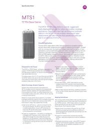
Enjoy the ultimate operating ease with your <strong>FT</strong>-<strong>950</strong>… External DataManagement Unit (DMU-2000 : Option) to enhance your DX operation!A wide array of information, useful and enjoyable displays, identical to those availableon the <strong>FT</strong> DX 9000 Series and the <strong>FT</strong>-2000 Series, can also be yours by addingthe optional DMU-2000 Data Management Unit and an after-market PC display (not supplied).PC monitor display and keyboard are after-market items, not supplied with the <strong>FT</strong>-<strong>950</strong>.The MD-200A8X Desktop Deluxe Dynamic Microphone, the FH-2 Remote Control Keypadand the DMU-2000 Data Management Unit are optional items.DMU-2000 Data Management Unit (Option)like. By sweeping just a limited portion of the main Band Scope at high speed,you will get a superbly detailed view of activity in that segment of the overallband, allowing you precise zero-in capability not found with competingproducts. With a 50% bandwidth reduction, you will get double the speed;with reduction to 30% of the original sweep, you will get a 3X increasein speed, and by reducing the bandwidth to 10% you will get a whopping10X increase in the sweep speed. You can use the " " and " " keys to movethe remaining window, as desired. You may choose the Spectrum ScopeFunction (which will plot your current operating frequency in the middleof the monitor screen) or the Band Monitor Function (which will be checkingthe whole band you are currently operating). With the Band MonitorFunction, you will be able to set the lowest starting frequency to yourpreference (for CW or SSB operation). Once you have set it up, the loweststarting frequency will not be purged, even if you change your bandwidth.DMU-2000 : InsideDMU-2000 Data Management Unit (Option)After-market PS/2 Keyboard and PC monitor display are required for use of DMU-2000 and are not supplied.Spectrum Scope with LBWSThe RF Band Scope allows you to view activity within a span of 25 kHz,100kHz, 250kHz, 500kHz, 1 MHz, or 2.5 MHz, depending on yourrequirements, with a fixed sweep speed for seamless transition between spans.Additionally, the YAESU-exclusive LBWS (Limited Band WidthSweep) allows you to reduce the bandwidth to 50%, 30%, or 10% of theoriginal, imparting a corresponding increase in the sweep speed, if you9
Audio Scope/Oscilloscope Display FunctionThe Audio Scope Function and the Oscilloscope Function of the DMU-2000 may be the most useful capability of the Data Management Unit.The Audio Scope portrays the audio spectrum of either the receiverpassband or your transmitted signal, allowing you to visualize the frequencycomponents as you hear them.This function also enables you to makeadjustments to the Notch Filter, Contour control or (on transmit) theParametric Microphone Equalizer.At the same time, you may use the Oscilloscope to look at the X-Ycharacteristics of an incoming signal with variable level and sweepspeed, or to check CW tone pitch, etc.World Clock DisplayThe World Clock function includes a world map with entries for anumber of locations throughout the world.You will see the time of dayat the other end or anywhere in the world.Of great value to seriousDxers is the Sunrise/Sunset depiction, which shows the "Gray Line"area where propagation frequently is enhanced.An alarm feature isalso included, to alert you of a schedule time.• Spectrum Scope DisplaySwept-Frequency SWR Display• Waterfall DisplayAs you tune across the Amateur band and transmit at differentfrequencies, the DMU-2000 will plot the SWR across the band,alerting you to any unusual SWR situations, etc.Rotator Control FunctionThe Rotator Control Function includes the Great Circle Map that allowsyou to aim your directional antenna accurately (e.g. Tokyo seems to belocated West from San Francisco though it is more actually located tothe NNW direction) and the imbedded database of worldwide citiesmay be used to determine a specific bearing to a DX location, if you like.The Rotator Control function further lets you control the left(C-C-W)/right(C-W) rotation of your Yaesu G-800/1000/2800DXA seriesrotator, in addition to permitting speed control and setup of presetbeam headings.And, if you use your after-market keyboard for input ofyour latitude and longitude, the DMU-2000 will compute and display aGreat Circle Map centered on your location! You may also connect aGPS Unit (one capable of output of NMEA0183 position data) to yourDMU-2000 to download precise position data.Memory Channel ListYou may easily edit and confirm your memory frequency channels onyour big screen.You can add alpha/numeric "Tags" to each memory forquick recall of the channel's identification.Log Book FeatureBy connecting an after-market keyboard and monitor to the DMU-2000, you can utilize the on-board logging capability of the <strong>FT</strong>-2000.The Log Book includes an extensive database of DX information, andyou may archive your log data to the supplied CF card using one of thepopular and available logging formats like ADIF, Cabrillo, etc.10
SpecificationsGeneralRx Frequency Range 30 kHz - 56 MHz (operating)160 -6m(specified performance, Amateur bands only)Tx Frequency Ranges 160 -6m(Amateur bands only)Frequency Stability ±0.5 ppm(after 1 minute @77° F [+25° C])±1.0 ppm (after 1 minute @14° F~+122° F [Ð10° C~+50° C])Operating Temperature Range 14° F~+122° F (Ð10° C~+50° C)Emission Modes A1A (CW), A3E (AM), J3E (LSB, USB), F3E (FM),F1B (RTTY), F1D (PACKET), F2D (PACKET)Frequency Steps 1/10 Hz (SSB, CW, & AM), 100 Hz (FM)Antenna Impedance 50 Ohms, unbalanced16.7 - 150 Ohms, unbalanced(Tuner ON, 160 -6mAmateur bands, TX only)Power Consumption (Approx.) Rx (no signal) 1.8 ARx (signal present) 2.1 ATx (100 W)22 ASupply Voltage DC 13.8 V ±10% (Negative Ground)Dimensions (WxHxD): 14.4" x 4.5" x 12.4" (365 x 115 x 315 mm)Weight (Approx.) 21.6 lbs (9.8 kg)TransmitterPower Output 5 - 100 watts (2 - 25 watts AM carrier)Modulation Types J3E (SSB): Balanced,A3E (AM): Low-Level (Early Stage),F3E (FM): Variable ReactanceMaximum FM Deviation ±5.0 kHz / ±2.5 kHzHarmonic Radiation Better than –60 dB (160 - 10m Amateur bands: Harmonics)Better than –50 dB (160 - 10mAmateur bands: Others)Better than –65 dB (6mAmateur band)SSB Carrier Suppression At least 60 dB below peak outputUndesired Sideband Suppression At least 60 dB below peak output3rd-order IMD –31 dB @14 MHz 100 watts PEPBandwidth3 kHz (LSB/USB), 500 Hz (CW),6 kHz (AM), 16 kHz (FM)Audio Response (SSB) Not more than –6 dBfrom300 to 2700 HzMicrophone Impedance 600 Ohms (200 to 10 kOhms)¥ Supplied Accessories: MH-31B8 Hand Microphone (1), DC Cable (1)OptionsReceiverCircuit TypeTriple-conversion SuperheterodyneIntermediate Frequencies 69.450 MHz/450 kHz/30 kHz (24 kHz for AM/FM)SensitivitySSB (BW: 2.4 kHz, 10 dB S+N/N)4 µV (0.5 - 1.8 MHz) (IPO "ON")0.2 µV (1.8 - 30 MHz) (AMP 2)0.125 µV (50 - 54 MHz) (AMP 2)AM (BW: 6 kHz, 10 dB S+N/N, 30 % modulation @400 Hz)28 µV (0.5 - 1.8 MHz) (IPO "ON")2 µV (1.8 - 30 MHz) (AMP 2)1 µV (50 - 54 MHz) (AMP 2)FM (BW: 15 kHz, 12 dB SINAD)0.5 µV (28 - 30 MHz) (AMP 2)0.35 µV (50 - 54 MHz) (AMP 2)There is no specification for frequency ranges not listed.Squelch Sensitivity SSB/CW/AM(RF AMP 2 ÒONÓ)2 µV (0.1 - 1.8 MHz)2 µV (50 - 54 MHz)FM1 µV (28 - 30 MHz)1 µV (50 - 54 MHz)There is no specification for frequency ranges not listed.Selectivity (WIDTH: Center) Mode –6 dB –60 dBCW/RTTY/PKT 0.5 kHz or better 750 Hz or lessSSB 2.4 kHz or better 3.6 kHz or lessAM 6 kHz or better 15 kHz or lessFM 15 kHz or better 25 kHz or lessImage Rejection 70 dB or better (160 - 10m Amateur bands)60 dB or better (6mAmateur band)Maximum Audio Output 2.5 W into 4 Ohms with 10% THDAudio Output Impedance 4to8Ohms (4 Ohms: nominal)Conducted Radiation Less than 4000 µµWDMU-2000 Data Management Unit SpecificationsPower RequirementsAC 90 V ~ 264 V 50/60 HzCurrent Consumption (@117V AC)Typ. 50 VAWeight (approx.)5.9 lbs (2.7 kg)Dimensions (WxHxD) 3.9" x 5.3" x 13.8" (100 x 135 x 350 mm) (without knobs/switches)Specifications are subject to change, in the interest of technical improvement, without notice or obligation,and are guaranteed only within the amateur bands.•IncludesScope UnitCF Card UnitDMU-2000Data Management UnitAfter-market PS/2 Keyboardand PC monitor are requiredfor use of DMU-2000 andare not supplied.About this brochure: we have made this brochure as comprehensive and factual as possible. We reserve the right, however, to make changes at any time to equipment, optional accessories, specifications, modelnumbers, and availability. Precise frequency range may be different in some countries. Some accessories shown herein may not be available in some countries. Some information may have been updated sincethe time of printing; please check with your Authorized Yaesu Dealer for complete details.http://www.vertexstandard.comVERTEX STANDARD CO., LTD. VERTEX STANDARD Email: amateursales@vxstdusa.comFor the latest Yaesu news,visit us on the Internet:http://www.vxstd.com2007.0910NA(U/E)DVS-6Voice Memory UnitFH-2Remote Control KeypadRF µ-Tune Kits Wt. Abt. 5.7 Lbs (2.6 kg) /5Wx4.7Hx13Din(127 x 120 x 328 mm)160m Band 80/40m Band 30/20m BandRF µ-Tune Kits A RF µ-Tune Kits B RF µ-Tune Kits C•Up to three/3 µ-Tune Kits may be installed. All and any µ-Tune Kits shall be installed by the users.4-8-8 Nakameguro, Meguro-ku, Tokyo 153-8644, JapanB9200576MD-200A8XDesktop Deluxe DynamicMicrophoneHF-50 MHz 1 kW Linear Amplifier(50 MHz: 500 W/USA Version) VL-1000 Power SupplyVL-1000Automatic Antenna Tuner Built InVP-1000Printed in JapanMD-100A8XDesktop MicrophoneYH-77STAStereo HeadphonesUS Headquarters10900 Walker Street, Cypress, CA 90630, U.S.A.YAESU EUROPE B.V.P.O. Box 75525, 1118 ZN Schiphol, The Netherlandshttp://www.yaesu.co.ukYAESU UK LTD. Email: sales@yaesu.co.ukFC-40Automatic Antenna Tuner(for Long wire antenna)The FC-40 is a microprocessorcontrolledantenna impedancematching network designedto provide all-amateur-bandtransmitting capability with the<strong>FT</strong>-<strong>950</strong> of transceivers, whenused with an end-fed randomwire or long whip antenna.Specifications•Operating Frequency Range:1.8 - 54 MHzwith 66 ft (20+ m) end-fed wire, 7-54MHzwith 8 ft (2.5 m) Mobile Whip Antenna •InputImpedance:50-Ohms •Maximum Power:100 Watts (3 minutes Maximum ContinuousTX) •Matched SWR:2.0:1 or less (if antennais not a multiple of /2)•Tune-up Power:4 W~60W•Tune-up Time:8 seconds maximum•Impedance Matching Memories: 200channels •Power supply:13.8 V DC ±15%(supplied fromtransceiver) •Case Size(WHD):9" x 7" x 2.1" (228 x 175 x 55 mm)•Weight:2.6 lbs. (1.2 kg)Phone +1 714-827-7600Phone +31 20-5005270Unit 12, Sun Valley Business Park, Winnall ClosePhone +44 196 286 6667Winchester, Hampshire, SO23 0LB, U.K.VERTEX STANDARD HK LTD. http://www.vxstd.com.hkUnit 5, 20/F., Seaview Centre, 139-141 Hoi Bun Road, Phone +852 2732 2288Kwun Tong, Kowloon, Hong KongVERTEX STANDARD AUSTRALIA PTY. LTD.Normanby Business Park, Unit 14/45 Normanby Road Phone +61 3 95182100Notting Hill 3168, Victoria, Australia