TM 11-6625-274-12.pdf - Frank's electron Tube Data sheets
TM 11-6625-274-12.pdf - Frank's electron Tube Data sheets
TM 11-6625-274-12.pdf - Frank's electron Tube Data sheets

Create successful ePaper yourself
Turn your PDF publications into a flip-book with our unique Google optimized e-Paper software.
<strong>TM</strong> <strong>11</strong>-<strong>6625</strong>-<strong>274</strong>-12DEPAR<strong>TM</strong>ENT OF THE ARMY TECHNICAL MANUALOPERATOR’S AND ORGANIZATIONALMAINTENANCEMANUALTEST SETS, ELECTRON TUBE TV-7/U,TV-7A/U, TV-7B/U AND TV-7D/UThis copy is a reprint which includes currentpages front Charges 6 and 7.HEADQUARTERS, DEPAR<strong>TM</strong>ENT OF THE ARMY14 JUNE 1960
W A R N I N GBe careful not to contact high-voltage connections or the <strong>11</strong>5-volt acinput connections when replacing tubes in the test set. Voltages up to300 volts ac may be encountered in this equipment. Serious injury ordeath may result from contact with these connections.DON’T TAKE CHANCES!
Changes in force: C6 and C7<strong>TM</strong> <strong>11</strong>-<strong>6625</strong>-<strong>274</strong>-12*C7CHANGENO. 7HEADQUARTERSDEPAR<strong>TM</strong>ENT OF THE ARMYWashington, DC, 9 January 1984O P E R A T O R ’ S A N D O R G A N I Z A T I O N A L M A I N T E N A N C EM A N U A L T E S T S E T S , E L E C T R O N T U B ET V - 7 / U ( N S N 6 6 2 5 - 0 0 - 3 7 6 - 4 9 3 9 ) ,T V - 7 A / U ( N S N 6 6 2 5 - 0 0 - 3 7 6 - 4 9 3 9 ) ,T V - 7 B / U ( N S N 6 6 2 5 - 0 0 - 3 7 6 - 4 9 3 9 ) ,A N DT V - 7 D / U ( N S N 6 6 2 5 - 0 0 - 8 2 0 - 0 0 6 4 )<strong>TM</strong> <strong>11</strong>-<strong>6625</strong>-<strong>274</strong>-12, 14 June 1960, is changedas follows:Page 7. Delete paragraphs 1.1, 2, and 2.1 andsubstitute:1.1. Consolidated Index of Army Publicationsand Blank FormsRefer to the latest issue of DA Pam 310-1 todetermine whether there are new editions,changes or additional publications pertaining tothe equipment.2. Maintenance Forms, Records, and Reportsa. Reports of Maintenance and UnsatisfactoryEquipment. Department of the Army forms andprocedures used for equipment maintenance willbe those prescribed by <strong>TM</strong> 38-750, The ArmyMaintenance Management System.b. Report of Packaging and Handling Deficiencies.Fill out and forward SF 364 (Report ofDiscrepancy (ROD)) and prescribed in AR735-<strong>11</strong>-2/DLAR 4140.55/NAVMATINST 4355.73A/AFR 400-54/MCO 4430.3F.c. Discrepancy in Shipment Report (DISREP)(SF 361). Fill out and forward Discrepancy inShipment Report (DISREP) (SF 361) as prescribedin AR 55-38/NAVSUPINST 4610.33C/AFR 75-18/MCO P4610.19D/DLAR 4500.15.2.1. Reporting Errors and RecommendingImprovementsYou can help improve this manual. If you findany mistakes or if you know of a way to improvethe procedures, please let us know. Mailyour letter or DA Form 2028 (RecommendedChanges to Publications and Blank Forms)direct to:Commander, US Army Communications-ElectronicsCommand and Fort Monmouth,ATTN:DRSEL-ME-MP, Fort Mon-Mouth, New Jersey 07703. In either case, areply will be furnished direct to you.Paragraphs 2.2, 2.3 and 2.4 are added afterparagraph 2.1.2.2. Reporting Equipment improvementRecommendations(ElR)If your <strong>electron</strong> tube test set needs improvement,let us know. Send us an EIR. You, the user, arethe only one who can tell us what you don’t likeabout your equipment. Let us know why youdon’t like the design. Put it on an SF 368(Quality Deficiency Report). Mail it to Commander,US Army Communications-ElectronicsCommandand Fort Monmouth, ATTN:DRSEL-ME-MP, Fort Monmouth, New Jersey07703. We’ll send you a reply.2.3. Administrative StorageAdministrative Storage of equipment issued toand used by Army activities will have preventivemaintenance performed in accordance with thePMCS charts before storing. When removing theequipment from administrative storage thePMCS should be performed to assure operationalreadiness. Disassembly and repacking of equipmentfor shipment or limited storage are coveredin chapter 4 and <strong>TM</strong> 740-90-1.2.4. Destruction of Army Electronics MaterielDestruction of Army <strong>electron</strong>ics materiel to preventenemy use shall be in accordance with <strong>TM</strong>750-244-2.*This change supersedes C2, 30 Jan 1963; C4, 22 June 1966 and C5, 30 April 1974. 1
C7, <strong>TM</strong> <strong>11</strong>-<strong>6625</strong>-<strong>274</strong>-12Page 8. Add paragraph 5.1 after paragraph 5.5.1. Items Comprising an Operable EquipmentUsableNSN QTY Nomenclature, part No., and mfr code on code Fig. No.<strong>6625</strong>-00-376-4939 Test Set, Electron <strong>Tube</strong> TV-7/U, TV-7A, B/U:dynamic mutual conductance type; 0.6 to <strong>11</strong>7 V fil voltagerange meter indication; tube condition on 0 to 120 arbitraryscale; operating power requirements AC, 105 to125 V, 50 to 1000 Hz single phase; SW positions A thru E;portable type<strong>6625</strong>-00-820-0064Test Set, Electron <strong>Tube</strong> TV-7D/U: dynamic mutual conductancetype; 0.6 to <strong>11</strong>7 V fil voltage range; meter indication;tube condition on 0 to 120 arbitrary scale; operating powerrequirements AC, 105 to 125 V, 50 to 1000 Hz singlePhase; SW position A thru F, portable type consisting of:NOTEThe part number is followed by the applicable 5-digitFederal supply code for manufacturers (FSCM) identifiedin SB 708-42 and used to identify manufacturer,distributor, or Government agency, etc.NOTEIn usable on code column, number 1 refers to TV-7/U;number 2 refers to TV-7A/U; number 3 refers to TV-7B/U; number 4 refers to TV-7D/U.5935-00-732-1919 1 Adapter, Electron <strong>Tube</strong> Socket: SM-B-425536; 800635935-00-537-4056 1 Adapter, Electron <strong>Tube</strong> Socket: SM-C-179260; 800635935-00-305-<strong>11</strong>89 1 Adapter, Electron <strong>Tube</strong> Socket: SM-B-425538; 80063<strong>6625</strong>-00-684-<strong>11</strong>89 1 Adapter, Test: SM-B-425638; 80063<strong>6625</strong>-00-618-9928 1 Adapter, Test: SM-B-425639; 80063<strong>6625</strong>-00-618-9929 1 Adapter, Test: SM-B-425640; 800635935-00-808-1802 1 Adapter, Electronic <strong>Tube</strong> Socket: nuvistor tube socketadapter; 1050-127; 28569<strong>6625</strong>-00-069-1960 1 Adapter, Test: socket for GE Micro-Miniature 7077 and7486; 86-060; 04435<strong>6625</strong>-00-668-4683 2 Lead, Test: 12450-245; 28569<strong>6625</strong>-00-727-7065 2 Lead, Test: SM-B-425548; 800631,2,3,41,2,3,41,2,3,41,2,3,41,2,3,41,2,3,41,2,3,41,2,3,41,2,341,2,388844444Page 17, paragraph 18c. Delete the note. down to 10, turn the BIAS control knobPage 18, paragraph 21d note. Change the noteto full scale (100 on dial).to read:Page 22, chapter 3 heading. After the headingNOTEadd:If the meter pointer cannot be adjustedSection I. OPERATOR/CREW PREVENTIVE MAINTENANCECHECKS AND SERVICESDelete paragraphs 31, 32, 33 and figures <strong>11</strong> and equipment other than those issued with the12 and substitute: equipment.31. Scope of Operator’s Maintenance a. Preventive maintenance checks and servicesThe maintenance duties assigned to the operatorchart (par. 33.1).of Test Sets, Electron <strong>Tube</strong> TV-7/U, TV-7A/U, b. Visual inspection (par. 34).TV-7B/U, and TV-7D/U are listed below to-C . <strong>Tube</strong> replacement (par. 37).gether with a reference to the paragraph coveringthe specific maintenance function. Thed. Replacement of lamps (par. 39).duties assigned do not require tools or test2
32. GeneralNOTERefer to <strong>TM</strong> 750-244-2 for proper proceduresfor destruction of this equipmentto prevent enemy use.a. Operator/crew preventive maintenance isthe systematic care, servicing and inspection ofequipment to prevent the occurrence of trouble,to reduce downtime, and to maintain equipmentin serviceable condition. To be sure that your<strong>electron</strong> tube test set is always ready for yourmission, you must do scheduled preventivemaintenance checks and services (PMCS).(1) BEFORE OPERATION, perform your BPMCS to be sure that your equipment is readyto go.(2) When an item of equipment is reinstalledafter removal, for any reason, perform thenecessary B PMCS to be sure the item meets thereadiness reporting criteria.(3) Use the ITEM NO. column in the PMCStable to get the number to be used in the <strong>TM</strong>ITEM NO. column on DA Form 2404 (EquipmentInspection and Maintenance Worksheet)when you fill out the form.b. Routine checks like CLEANING, DUST-ING, WASHING, CHECKING FOR FRAYEDCABLES, STOWING ITEMS NOT IN USE,COVERING UNUSED RECEPTACLES,CHECKING FOR LOOSE NUTS AND BOLTSAND CHECKING FOR COMPLETENESS arenot listed as PMCS checks. They are things thatyou should do any time you see they must bedone. If you find a routine check like one ofoperators reported problems with this item.NOTEWhen you are doing any PMCS orroutine checks, keep in mind the warningsand cautions.WARNINGSAdequate ventilation should be providedwhile using TRICHLOROTRIFLUORO-ETHANE. Prolonged breathing of vaporshould be avoided. The solvent shouldnot be used near heat or open flame; theproducts of decomposition are toxic andirritating. Since TRICHLOROTRI-FLUOROETHANE dissolves natural oils,prolonged contact with skin should beavoided.C7, <strong>TM</strong> <strong>11</strong>-<strong>6625</strong>-<strong>274</strong>-12When necessary, use gloveswhich the solvent cannot penetrate. Ifthe solvent is taken internally, consulta physician immediately.Compressed air is dangerous and cancause serious bodily harm if protectivemeans or methods are not observed toprevent a chip or particle (of whateversize) from being blown into the eyes orunbroken skin of the operator or otherpersonnel. Goggles must be worn at alltimes while cleaning with compressedair. Compressed air shall not be usedfor cleaning purposes except wherereduced to less than 29 pounds persquare inch gage (psig) and then onlywith effective chip guarding and personnelprotective equipment. Do notuse compressed air to dry parts whentrichlorotrifluoroethane has been used.NOTESThe PROCEDURES column in yourPMCS charts instruct how to performthe required checks and services. Carefullyfollow these instructions and, iftools are needed or the chart so instructs,get organizational maintenanceto do the necessary work.If your equipment must be in operationall the time, check those items that canbe checked and serviced without disturbingoperation. Make the completechecks and services when the equipmentcan be shut down.c. Deficiencies that cannot be corrected mustbe reported to higher category maintenancepersonnel.Records and reports of preventivemaintenance must be made in accordance withprocedures given in <strong>TM</strong> 38-750.33. Operator/Crew Preventive MaintenanceChecks and ServicesPerform before operation PMCS if you areoperating the item for the first time.NOTEThe checks in the interval column are tobe performed in the order listed.Page 23. Add paragraph 33.1 after paragraph 33.3
C7, <strong>TM</strong> <strong>11</strong>-<strong>6625</strong>-<strong>274</strong>-1233.1. Operator/Crew Preventive MaintenanceChecks and Services ChartB-BeforeInterval Procedures - Check for and have Equipment is notItem Item to be repaired or adjusted as Ready/AvailableNo. B Inspected necessary If:1 * Mission Check for completeness and Available equipmentEssential satisfactory condition is insufficient toEquipment of the equipment. Report support the combatmissing items.mission2 TV-7(*)/U Accomplish starting procedureTest Set as described in paragraph 17.*This check to be performed prior to redeployment or prior to reissue after repair or overhaul.Add Section II and paragraphs 33.2 and 33.3after paragraph 33.1 as follows:Section II. ORGANIZATIONAL PREVENTIVE MAINTENANCECHECKS AND SERVICES33.2. Organizational Maintenance checks and services, described in paragraph 33.3dures are designed to help maintain equipmentOrganizational preventive maintenance proceoutlineinspections that are to be made atspecific monthly (M) intervals.in serviceable condition. They include items to 33.3. Organizational Preventive Maintenancebe checked and how to check them. TheseM-MonthlyChecks and Services ChartItemIntervalItem to beNo. M Inspected Procedures1 TV-7(*)/U Accomplish performanceTest Setcheck as described inparagraph 35.Page 30. Change title of chapter 4 to “SHIP-MENT AND LIMITED STORAGE”.Page 32. Delete section II in its entirety.Page 33. Delete appendix I and substitute:APPENDIX IREFERENCESThe following is a list of applicable references available to the operator or organizational maintenancepersonnel of Test Set, Electron <strong>Tube</strong> TV-7(*)/U.DA Pam 310-1SB 38-100Consolidated Index of Army Publication and Blank Forms.Preservation, Packaging, Packing and Marking Materials, Supplies andEquipment Used by the Army.<strong>TM</strong> <strong>11</strong>-<strong>6625</strong>-<strong>274</strong>-24P Organizational, Direct Support and General Support Maintenance4Repair Parts and Special Tools Lists (Including Depot Maintenance
C7, <strong>TM</strong> <strong>11</strong>-<strong>6625</strong>-<strong>274</strong>-12Repair Parts and Special Tools) for Test Sets, Electron <strong>Tube</strong> TV-7A/U. (NSN <strong>6625</strong>-00-376-4939), TV-7B/U (<strong>6625</strong>-00-376-4939)and TV-7D/U (<strong>6625</strong>-00-820-0064).<strong>TM</strong> 38-750The Army Maintenance Management System (TAMMS).<strong>TM</strong> 740-90-1Administrative Storage of Equipment,<strong>TM</strong> 750-244-2Procedures for Destruction of Electronics Materiel to PreventEnemy Use.Page 34. Appendix II deleted.5
By Order of the Secretary of the Army:Official:JOHN A. WICKHAM JR.General, United States ArmyChief of StaffROBERT M. JOYCEMajor General, United States ArmyThe Adjutant GeneralDISTRIBUTION:To be distributed in accordance with DA Form 12-36B, Operatorand Crew Maintenance requirements for TV-7A-D/U.
SECTION II MAlNTENANCE ALLOCATION CHARTFORTEST SETS ELECTRON TUBE TV-7/U, TV-7A/U, TV-7B/U AND TV-7D/U(4)(1) (2) (3)MAINTENANCE CATEGORY (5)(6)GROUPCOMPONENT/ASSEMBLY MAINTENANCE TOOLS REMARKSNUMBERFUNCTION C O F H D ANDEQPT.00 TUBE TESTER TV-7U Service 0.5 2, <strong>11</strong>, 13TV-7A/U Test 0.5 1, 4, 14-18TV-7B/U Calibrate 1.5 1-10TV-7D/U Repair 0.5 ARepair 3.0 1-10, 12
SECTION III TOOL AND TEST EQUIPMENT REQUIREMENTSFORTEST SET ELECTRON TUBE TV-7/U, TV-7A/U, TV-7B/U AND TV-7D/UCOLOR TEST MAINTENANCEEQUIPMENTNOMENCLATURENATIONAL/NATOCATEGORYSTOCK NUMBERREF CODE1 HD TUBE SOCKET ADAPTER MX-1258/U <strong>6625</strong>-00-301-08152 HD *VOL<strong>TM</strong>ETER ME-459/U <strong>6625</strong>-00-229-04573 HD VARIABLE TRANSFORMER CN-16/U 5950-00-235-20864 HD MULTI METER TS-352 (*)/U <strong>6625</strong>-00-242-50235 HD RESISTOR FIXED (10,000 OHMS) 5905-00-<strong>11</strong>7-41946 HD ISOLATION TRANSFORMER 5950-00-498-21467 HD DECADE RESISTOR ZM-16/U <strong>6625</strong>-00-669-02668 HD RESISTOR FIXED (12,000 OHMS) 5905-00-107-51489 HD RESISTOR FIXED (100,000 OHMS) 5905-00-120-089410 HD RESISTOR FIXED (375,000 OHMS)<strong>11</strong> HD RESISTOR FIXED (510,000 0HMS) 5905-00-279-251612 HD LIGHT ASSEMBLY MX-1292 6695-00-378-544913 H TOOL KIT ELECTRONIC EQUIPMENT TK-1OO 5180-00-605-007914 D ELECTRON TUBE OC3 5960-00-864-751615 D ELECTRON TUBE 5Y3 5960-00-262-021816 D ELECTRON TUBE 6AU6 5960-00-169-934617 D ELECTRON TUBE 6L6 5960-00-228-005418 D ELECTRON TUBE 5678 5960-00-230-5262TOOL NUMBER*IF THE ME-459/U VOL<strong>TM</strong>ETER IS NOT AVAILABLE, ALL MODELS OF THEME-30(*)/U VOL<strong>TM</strong>ETER MAY BE USED.8
*<strong>TM</strong> <strong>11</strong>-<strong>6625</strong>-<strong>274</strong>-12T ECHNICALM ANUALNo. <strong>11</strong>-<strong>6625</strong>-<strong>274</strong>-12HEADQUARTERSDEPAR<strong>TM</strong>ENT OF THE ARMYWASHINGTON 25, D.C., 14 June 1960TEST SETS, ELECTRON TUBETV-7/U, TV-7A/U, TV-7B/U, AND TV-7D/UCHAPTER 1.INTRODUCTIONParagraphPageSection I.GeneralScope . . . . . . . . . . . . . . . . . . . . . . . . . . . . . . . . . . . . . . . . . . . . . . . . . . . . . . . . . . . . . . . . . . . . . . . . . . . . . . .Forms and records . . . . . . . . . . . . . . . . . . . . . . . . . . . . . . . . . . . . . . . . . . . . . . . . . . . . . . . . . .1237II.Description and dataPurpose and use . . . . . . . . . . . . . . . . . . . . . . . . . . . . . . . . . . . . . . . . . . . . . . . . . . . . . . . . . .Technical characteristics . . . . . . . . . . . . . . . . . . . . . . . . . . . . . . . . . . . . . . . . . . . . . . . . . . . . . . . . . . . . . . . . .Table of components . . . . . . . . . . . . . . . . . . . . . . . . . . . . . . . . . . . . . . . . . . . . . . . . . . . . . . . . . . . . . .Description of test set . . . . . . . . . . . . . . . . . . . . . . . . . . . . . . . . . . . . . . . . . . . . . . . . . . . . . . . . .Differences in models . . . . . . . . . . . . . . . . . . . . . . . . . . . . . . . . . . . . . . . . . . . . . . . . . . . . . . . . .3456777788CHAPTER 2.INSTALLATION AND OPERATING INSTRUCTIONSSection I.Service upon receipt of equipmentUnpacking . . . . . . . . . . . . . . . . . . . . . . . . . . . . . . . . . . . . . . . . . . . . . . . . . . . . . . . . . . . . . .Checking unpacked equipment. . . . . . . . . . . . . . . . . . . . . . . . . . . . . . . . . . . . . . . . . . . . . . . . . . .8910<strong>11</strong>II.Controls and indicatorGeneral . . . . . . . . . . . . . . . . . . . . . . . . . . . . . . . . . . . . . . . . . . . . . . . . . . . . . . . . . . . . . . . . . . . . . . . . . . . . . . . . . .Controls, indicators, and jacks . . . . . . . . . . . . . . . . . . . . . . . . . . . . . . . . . . . . . . . . . . . . . . . . . . . . . . . . . . .10<strong>11</strong><strong>11</strong><strong>11</strong>III.Operation under usual conditionsGeneral instructions . . . . . . . . . . . . . . . . . . . . . . . . . . . . . . . . . . . . . . . . . . . . . . . . . . . . . . . . . . . .Test leads . . . . . . . . . . . . . . . . . . . . . . . . . . . . . . . . . . . . . . . . . . . . . . . . . . . . . . . . . . . . . . . . . . . . . . . .<strong>Tube</strong> test sockets . . . . . . . . . . . . . . . . . . . . . . . . . . . . . . . . . . . . . . . . . . . . . . . . . . . . . . . . . . . . . . . . .<strong>Tube</strong> test data. . . . . . . . . . . . . . . . . . . . . . . . . . . . . . . . . . . . . . . . . . . . . . . . . . . . . . . . . . . . . . . . . . . . .Adapters . . . . . . . . . . . . . . . . . . . . . . . . . . . . . . . . . . . . . . . . . . . . . . . . . . . . . . . . . . . . . . . . . . . . . . .12131415161314141415IV.Operating test setStarting procedure . . . . . . . . . . . . . . . . . . . . . . . . . . . . . . . . . . . . . . . . . . . . . . . . . . . . . . . . . . . . . . . .Operating procedure. . . . . . . . . . . . . . . . . . . . . . . . . . . . . . . . . . . . . . . . . . . . . . . . . . . . . . . . . . . . . . . . . . . . .Checking filament continuity (12-volt Filament tubes) . . . . . . . . . . . . . . . . . . . . . . . . . . . .Reading meter . . . . . . . . . . . . . . . . . . . . . . . . . . . . . . . . . . . . . . . . . . . . . . . . . . . . . . . . . . . . . . . . . . . . . . . . . .Gas test . . . . . . . . . . . . . . . . . . . . . . . . . . . . . . . . . . . . . . . . . . . . . . . . . . . . . . . . . . . . . . . . . . . . . . . . . . . . . . .Noise test . . . . . . . . . . . . . . . . . . . . . . . . . . . . . . . . . . . . . . . . . . . . . . . . . . . . . . . . . . . . . . . . . . . . . . . .Panel lamp test . . . . . . . . . . . . . . . . . . . . . . . . . . . . . . . . . . . . . . . . . . . . . . . . . . . . . . . . . . . . . . . . . . . . . . . . .Testing special tube types . . . . . . . . . . . . . . . . . . . . . . . . . . . . . . . . . . . . . . . . . . . . . . . . . . . . . . . . . . .Testing subminiature tubes . . . . . . . . . . . . . . . . . . . . . . . . . . . . . . . . . . . . . . . . . . . . . . . . . . . . . . . . . .Stopping procedure . . . . . . . . . . . . . . . . . . . . . . . . . . . . . . . . . . . . . . . . . . . . . . . . . . . . . . . . . . . . . . . . . . .1718192021222324252616161718181919191920*This manual supersedes so much of <strong>TM</strong> <strong>11</strong>-5083, 29 September 1953, including C1, 2 September 1955; C2, 8February 1956, and C3, 1 April 1959, as pertains to operation and organizational maintenance; so much of C4, 26August 1959, as pertains to packaging and repackaging; <strong>TM</strong> <strong>11</strong>-<strong>6625</strong>-<strong>274</strong>-10P, <strong>11</strong> June 1959, and so much of <strong>TM</strong><strong>11</strong>-<strong>6625</strong>-<strong>274</strong>-20P, <strong>11</strong> June 1959, as pertains to the maintenance allocation chart.1
v.CHAPTER 3.CHAPTER 4.Section I.II.APPENDIX I.II.III.Operation under unusual conditionsGeneral . . . . . . . . . . . . . . . . . . . . . . . . . . . . . . . . . . . . . . . . . . . . . . . . . . . . . . . . . . . . . . . . . . . . . . . . . . . . . . . . . . . . . . . . . . . . . . . . . . . . . . . . . . . . . . . .Operation at low temperatures . . . . . . . . . . . . . . . . . . . . . . . . . . . . . . . . . . . . . . . . . . . . . . . . . . . . . . . . . . . . . . . . . . . . .Operation under tropical conditions . . . . . . . . . . . . . . . . . . . . . . . . . . . . . . . . . . . . . . . . . . . . . . . . . . . . . . . . . . . .Operation in desert climates . . . . . . . . . . . . . . . . . . . . . . . . . . . . . . . . . . . . . . . . . . . . . . . . . . . . . . . . . . . . . . . . . . . ....MAINTENANCE INSTRUCTIONSGeneral . . . . . . . . . . . . . . . . . . . . . . . . . . . . . . . . . . . . . . . . . . . . . . . . . . . . . . . . . . . . . . . . . . . . . . . . . . . . . . . . . . . . . . . . . . . . . . . . . . . . . . . . . . . . . . .Materials required . . . . . . . . . . . . . . . . . . . . . . . . . . . . . . . . . . . . . . . . . . . . . . . . . . . . . . . . . . . . . . . . . . . . . . . . . . . . . . . . . . . . . . . . . . . .Preventive maintenance . . . . . . . . . . . . . . . . . .. . . . . . . . . . . . . . . . . . . . . . . . . . . . . . . . . . . . . . . . . .. . . . . . . . ......Visual inspection . . . . . . . . . . . . . . . . . . . . . . . . . . . . . . . . . . . . . . . . . . . . . . . . . . . . . . . . . . . . . . . . . . . . . . . . . . . . . . . . . . . . . . . . . . . . .Equipment performance checklist . . . . . . . . . . . . . . . . . . . . . . . . . . . . . . . . . . . . . . . . . . . . . . . . . . . . . . . . . . . . . . .Removal of chassis . . . . . . . . . . . . . . . . . . . . . . . . . . . . . . . . . . . . . . . . . . . . . . . . . . . . . . . . . . . . . . . . . . . . . . . . . . . . . . . . . . . . . . . . . .<strong>Tube</strong> replacement . . . . . . . . . . . . . . . . . . . . . . . . . . . . . . . . . . . . . . . . . . . . . . . . . . . . . . . . . . . . . . . . . . . . . . . . . . . . . . . . . . . . . . . . . . . . .Preferred-type tubes . . . . . . . . . . . . . . . . . . . . . . . . . . . . . . . . . . . . . . . . . . . . . . . . . . . . . . . . . . . . . . . . . . . . . . . . . . . . . . . . . . . . . . .Replacement of lamps . . . . . . . . . . . . . . . . . . . . . . . . . . . . . . . . . . . . . . . . . . . . . . . . . . . . . . . . . . . . . . . . . . . . . . . . . . . . . . . . . . . . . . .SHIPMENT, LIMITED STORAGE, AND DEMOLITIONTO PREVENT ENEMY USEShipment and limited storageRemoval from service . . . . . . . . . . . . . . . . . . . . . . . . . . . . . . . . . . . . . . . . . . . . . . . . . . . . . . . . . . . . . . . . . . . . . . . . . . . . . . . . . . . . .Repackaging for shipment or limited storage . . . . . . . . . . . . . . . . . . . . . . . . . . . . . . . . . . . . . . . . . . .Demolition of materiel to prevent enemy useAuthority for demolition . . . . . . . . . . . . . . . . . . . . . . . . . . . . . . . . . . . . . . . . . . . . . . . . . . . . . . . . . . . . . . . . . . . . . . . . . . . . . . .Methods of destruction . . . . . . . . . . . . . . . . . . . . . . . . . . . . . . . . . . . . . . . . . . . . . . . . . . . . . . . . . . . . . . . . . . . . . . . . . . . . . . . . . . . .ParagraphREFERENCES . . . . . . . . . . . . . . . . . . . . . . . . . . . . . . . . . . . . . . . . . . . . . . . . . . . . . . . . . . . . . . . . . . . . . . . . . . . . . . . . . . . . . . . . . . . . . . . . . . . . . . . . . . . .OPERATOR’S MAINTENANCE REPAIR PARTS ANDSPECIAL TOOLS LIST . . . . . . . . . . . . . . . . . . . . . . . . . . . . . . . . . . . . . . . . . . . . . . . . . . . . . . . . . . . . . . . . . . . . . . . . . . . . . . . . . . . . . . . .MAINTENANCE ALLOCATION CHART . . . . . . . . . . . . . . . . . . . . . . . . . . . . . . . . . . . . . . . . . . . . . . . . . . . . . . . . . . . . .2728293031323334353637383940414243Page20212121222222252527272828303032323334372
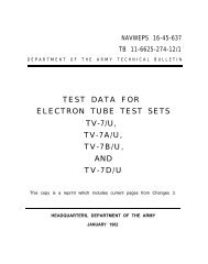
CHAPTER 1INTRODUCTIONSection I. GENERAL1. Scopea. This manual describes Test Sets, ELectron<strong>Tube</strong> TV-7/U (fig. 1), TV-7A/U (fig. 2),TV-7B/U (fig. 3), and TV-7D/U (fig. 4), andcovers installation, operation, and first andsecond echelon maintenance. It includes in-structions for operation under usual and unusualconditions, cleaning and inspection ofthe equipment, and replacement of parts avail-able to first and second echelon maintenancepersonnel.<strong>TM</strong><strong>6625</strong>-<strong>274</strong>-12-1Figure 1. Test Set, Electron <strong>Tube</strong> TV-7/U, less running spares.3
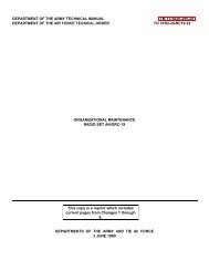
Figure 2. Test Set, Electron <strong>Tube</strong> TV-7A/U, less running Spares.<strong>TM</strong><strong>6625</strong>-<strong>274</strong>-12-144
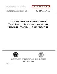
<strong>TM</strong><strong>6625</strong>-<strong>274</strong>-12-2Figure 3. Test Set, Electron <strong>Tube</strong> TV-7B/U, less running spares.5
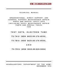
6Figure 4. Test Set, Electron <strong>Tube</strong> TV-7D/U, less running spares.
. Official nomenclature followed by (*) isused to indicate all models of the equipmentitem covered in this manual. Thus, Test Set,Electron <strong>Tube</strong> TV-7(*)/U represents TestSets, Electron <strong>Tube</strong> TV-7/U, TV-7A/U, TV-7B/U, and TV-7D/U.2. Forms and Recordsa. Electronic Failure Report. Fill out andforward DD Form 787-1, Electronic FailureReport-Signal Equipment, to the CommandingOfficer, U.S. Army Signal Equipment SupportAgency, Fort Monmouth, N.J., as prescribedin AR 700-39.b. Unsatisfactory Equipment Report. Fillout and forward AF TO Form 29, UnsatisfactoryReport, to the Commander, Air MaterielCommand, Wright-Patterson Air ForceBase, Ohio, as prescribed in AF TO 00-35D-54.c. Report of Damaged or Improper Shipment.Fill out and forward DD Form 6, Reportof Damaged or Improper Shipment, asprescribed in AR 700-58 (Army), Navy ShippingGuide, Article 1850-4 (Navy), and AFR71-4 (Air Force).d. Preventive Maintenance Form. PrepareDA Form <strong>11</strong>-266 (fig. <strong>11</strong> and 12), MaintenanceCheck List for Signal Equipment (Test Equipment),in accordance with instructions on theform.e. Parts List Form. Any comments concerningomissions and discrepancies in appendixII or III in this manual will be preparedon DA Form 2028 and forwarded directly tothe Commanding Officer, U.S. Army SignalEquipment Support Agency, Fort Monmouth,N.J. ATTN: SIGFM/ES-ML.f. Comments on Manual. Forward all othercomments on this manual direct to the CommandingOfficer, U.S. Army Signal PublicationsAgency, Fort Monmouth, N.J.Section II DESCRIPTION AND DATA3. Purpose and UseTest Set Electron <strong>Tube</strong> TV-7(*)/U is aportable tube tester of the dynamic mutualconductance type. It is used to test and tomeasure performance capabilities and to determinerejection limits for <strong>electron</strong> tubes usedin receivers, low-powered transmitters, andmany other <strong>electron</strong>ic equipments. The followingtests can be made with Test Set Electron<strong>Tube</strong> TV-7(*)/U:a. Continuity test (ballast tubes).b. Dynamic mutual conductance test (amplifiertubes).c. Emission test (rectifier tubes).d. Gas test (amplifier tubes).e. Noise test.f. Panel lamp test.g. Shorts test.4. Technical CharacteristicsPower Supply:Input voltage . . . . . . 103.5 to 126.5 Volts ac,single phase.Frequency . . . . . . 50 to 1,000 cps.Power consumption . . 45 watts at <strong>11</strong>5 volts,50 cps.Meter . . . . . . . . . . . . . . . . . . . . . 0 to 120 arbitraryunits.Operating tempera- -40° to + 125°ture limitsFahrenheit.Number of tubes . . . . . . . 2.Indicator lights:PILOT . . . . . . . . . . . . . . . . One type 47.SHORTS . . . . . . . . . . . . . One type NE-45.FUSE . . . . . . . . . . . . . . . . . . One type 81.5. Table of ComponentsThe components of Test Set, Electron <strong>Tube</strong>TV-7(*)/U are listed in a below and the spareparts in b below.7
a. Components.QuantityItemDimensions (In.)HeightDepthLengthU n i tweight (lb)<strong>11</strong>Test set including tubes and lamps . . . . . . . . . . . . . . . . . . . . . . . . . . . . . . .Adapter E105: 3E29, 829-B or 832-A tubes . . . . . . . . . . . . . . . . . .6 1/16181Adapter E107: 2C39 tube . . . . . . . . . . . . . . . . . . . . . . . . . . . . . . . . . . . . . . . . . . . .1Adapter E104: Subminiature tubes . . . . . . . . . . . . . . . . . . . . . . . . . . . . . . . . . . .1Adapter X10B: socket saver, 7-pin miniature (TV-7D/U) . . . . . . .1Adapter X7B: socket saver, 9-pin miniature (TV-7D/U). . . . . . . .1Adapter X3B: socket saver, octal (TV-7D/U) . . . . . . . . . . . . . . . . . . . . .2Test leads . . . . . . . . . . . . . . . . . . . . . . . . . . . . . . . . . . . . . . . . . . . . . . . . . . . . . . . . . .1 setRunning spares (b below) . . . . . . . . . . . . . . . . . . . . . . . . . . . . . . . . . . . . . . . . . .1 5b. Spare Parts.QuantityItem1 Electron tube, type 5Y3WGTA1 Electron tube, type 831 Lamp, neon NE-451 Lamp, incandescent No. 471 Lamp, incandescent No. 816. Description of Test Set(fig. 1-4)a. Test Set, Electron <strong>Tube</strong> TV-7(*)/U(test set) is self-contained in a carrying caseequipped with a carrying handle. The coveris secured to the case by luggage-type fasteners.Retainer brackets on the inside of thecover are used to secure and store the powercable, pin straighteners for 7- and 9-pin miniaturetubes, and adapters (par. 16). A ringbinder inside the cover holds TB <strong>11</strong>-5083-1(tube test data book (par. 15)). The cover ishinged by slip hinges and can be removed fromthe case.b. An indicating meter and all controls,knobs, pushbuttons, sockets, and indicatinglamps are on the front panel. The necessarydata for setting and operating the controls totest the various tube types are contained in thetube test data book (a above). One end of thealternating current (ac) line cord is permanentlyattached to the panel; the other endterminates in a male plug.7. Differences in ModelsTest Sets, Electron <strong>Tube</strong> TV-7(*)/U aresimilar in purpose, operation, and appearance.Some models have been modified to improveoperational features. External differences areas follows:ItemTV-7/UTV-7A/UTV-7B/7TV-7D/UF RANGE on FUNCTIONSWITCH.Not used.Not used.Not used.Used.BIAS and SHUNT controls . . . . . . . .Markings engravedon adial.Markings etchedinto test setpanel.Markings etchedinto test setpanel.Markings etchedinto test setpanel.SHORTS lamp . . . . . . . . . . . . . . . . . . .No panelmarking.Panel marking.Panel marking.Panel marking.Subminiature tube test socketX109.Rectangular.Round on someequipments.Rectangular.Rectangular.Storage clip for ac line cord plug.Not used.Used.Used.Used.Storage clips for test leads . . . . . . . .Not used.Not used.Used.Used.Tip of test lead plug (2 each) . . . .3/32-inchdiameter.5/64-inchdiameter.3/32-inchdiameter.3/32-inchdiameter.8
nom TV-71U TV-7A/U Tv.78/uIITV-7D/UGrid (G), plate (P), and NOISE Accommodates Accommodates Accommodates Accommodatesjacks. 3 I 32-inch 6/64-inch 3132-inch 3132-inchdiameter tip diameter tip diameter tip diameter tipplugs. plugs. plugs. plugs.Gasket around edge of cover . . . . . . Not used. Used. Used. used.Socket saver adapters X1OB, X7B, Not provided. Not provided. Not provided. Provided.and X3B, 7-pin and 9-pin miniatureand octal base.9
CHAPTER 2INSTALLATION AND OPERATING INSTRUCTIONSSection I SERVICE UPON RECEIPT OF EQUIPMENT8. Unpackinga. Packaging <strong>Data</strong>. When packed for shipment,the test set is packaged in an innerfiberboard carton. Spare parts are in a small,corrugated carton, protected by a sleeve ontop of the test set. The inner fiberboard cartonis sealed with gummed tape, and is then placedwithin an outer fiberboard carton, with allseams and joints sealed with water-resistant,pressure-sensitive tape. A wooden packingcase may also be used when a multiple of fourtest sets is shipped. The wooden packing casewill be strapped only for intertheater shipment.A typical packing case and its contentsare shown in figure 5.(1)(2)The inside dimensions of a packingcase that contains four packaged testsets is approximately byby inches; the volume is 4.8cubic feet, and the weight is 106pounds.The outside dimensions of a test setpacked in fiberboard cartons isby by inches; the volume is<strong>TM</strong><strong>6625</strong>-<strong>274</strong>-12-4Figure. 5. Typical packaging.10
1.2 cubic feet, and the weight is (6) Open the inner fiberboard carton andpounds.remove the contents.b. Removing Contents. 9. Checking Unpacked Equipment(1)(2)(3)(4)(5)Cut and fold back the metal straps Check the equipment against the packing(when used).list. When no packing list accompanies theequipment, use the table of components (par.Remove the nails from the wooden5) as a general check. If the equipment iscover and one side of the woodendamaged, refer to paragraph 2. After a test setpacking case with a nailpuller. Removethe cover and the side. Do notis removed from its fiberboard container, releasethe fasteners, open the cover, and proceedattempt to pry off the cover or theas follows:side; prying may damage the equipment.a. Check to see that the adapters (fig. 8)are held firmly to the cover.Remove the envelope that contains the b. Check all controls for ease of rotation.technical manuals.Tighten loose knobs.c. Check for a broken meter glass andRemove the outer fiberboard cartonbroken lamps.from the wooden packing case.d. Check the ac line cord, test leads, andOpen the outer fiberboard carton and rubber gasket around the edge of the coverremove the inner fiberboard carton. (except on TV-7/U) for signs of deterioration.Section II. CONTROLS AND INDICATORS10. GeneralImproper setting of the FILAMENT VOLT-AGE switch (fig. 6) or incorrect operation ofthe pushbutton switches may damage the tubeunder test. Be sure that all the controls andswitches are set properly before testing tubes.<strong>11</strong>. Controls, Indicators, and Jacksa. Switches and Controls.Switch or controlPOWER switch . . . . . . . . . . . .FILAMENT VOLT-AGE (20-positionrotary switch)ON:OFF:FunctionConnects acpower to testset.Removes acpower fromtest set.Provides an 18-step selectionof filament voltages from0.6-volt to <strong>11</strong>7 volts ac.BLST.: Enables ballasttubes to betested for continuityandsupplies voltageto certainrectifier tubesfor emissiontests.Switch or controlFILAMENT selectors,left and right (10-position, 5-sectionrotary switches)GRID selector (10-position,5-sectionrotary switch)PLATE selector (10-position, 5-sectionrotary switch)SCREEN selector (10-position, 5-sectionrotary switch)CATHODE selector(10-position rotaryswitch, 0-positionopen)SUPPRESSOR selector(10-position rotaryswitch, 0-positionopen)OFF:FunctionRemoves voltagefrom FILA-MENT VOLT-AGE switch.Connects filament of tubeunder test to filament voltagesupply.When set in one of positions1-9, connects control gridof tube under test to biasand signal voltages.When set in one of positions1-9, connects plate of tubeunder test to plate voltagesupply.When set in one of positions1-9, connects screen grid oftube under test to screenvoltage supply.When set in one of positions1-9, connects cathode oftube under test to desiredtest circuit.When set in one of positions1-9, connects suppressorgrid of tube under test todesired test circuit.<strong>11</strong>
Switch or controlFUNCTION SWITCH(<strong>11</strong>-position, 8-sectionrotary switch(TV-7D/U), 10-position, 6-sectionrotary switch on allother models)LINE ADJUST controlBIAS control. . . . . . . . . . . . . .SHUNT control . . . . . . . . . . .b. Pushbutton Switches.Pushbutton switch1-LINE ADJ . . . . . . .2-DIODE . . . . . . . . . . . . .3-MUT. COND. . . . .FunctionSHORTS: Positions 1-5 connectvariouselements oftube under testto shorts testcircuit.RANGES: Positions A-E(A-F, TV-7D/U) controlsensitivity ofmeter circuitand magnitudeof signal voltage.Adjusts amount of inputvoltage to power transformer.Adjusts amount of bias voltageapplied to tube undertest.Adjusts sensitivity of metercircuit.Switch positionFunctionActionDepressed Connects meter intoline test circuit.NormalDisconnects meterfrom line test circuit.Depressed Connects diode tubeunder test to anac test voltage,and connects lowscreen grid voltage(if required)to tube under testwhen pushbutton3-MUT. COND.is depressed. aNormalRemoves ac testvoltage from diodeunder test andconnects normalscreen grid voltage(if required)to tube under testwhen pushbutton3-MUT. COND.is depressed.Depressed Connects tube undertest to plate andscreen grid (whenrequired) voltages.Pushbutton switch4-GAS 1 . . . . . . . . . . . . . .5-GAS 2 (usedwith 4-GAS 1when amplifiertubes are testedfor gas)6-OZ4. . . . . . .7-RECT. . . . . . . . . . . . . .8-METER REV. . . . .Switch positionNormalDepressedNormalDepressedNormalDepressedNormalDepressedNormalDepressedNormalFunctionActionRemoves plate andscreen grid (whenused) voltagesfrom tube undertest.Connects ac testvoltage to certaindiode tubes andconnects platevoltage and biasvoltage to tubeunder test whenchecking amplifiertubes for gas.Removes diode testvoltage or platevoltage andbias voltage fromamplifier tubeunder test.Connects a resistorinto control gridcircuit of tube undertest.Short-circuits resisterin controlgrid circuit oftube under test.Connects tube undertest to an ac testvoltage. aRemoves ac voltagefrom tube undertest.Connects tube undertest to an ac testvoltage. aRemoves ac voltagefrom tube undertest.Reverses polarity ofvoltage applied tometer.Permits normal polarityof voltageto be applied tometer.a Voltage will vary slightly, depending on LINE ADJUST setting.c. Meter, Indicator Lamps, and Jacks.Note. The jacks on the TV-7A/U accommodate5/64-inch diameter tip plugs; the jacks on all othermodels of the test set accommodate 3/32-inch diametertip plugs.12
Meter, indicator lamp,or jackFunctionMeter, indicator lampor jackFunctionMeter . . . . . . . . . . . . . . . . . .SHORTS lamp (nota panel markingon TV-7/U)PILOT lamp . . . . . . . . . .Indicates condition of tube undertest. A LINE TEST mark atmidscale is used to establishcorrect input voltage to powertransformer.Indicates and locates shortedtube elements.Indicates when power is deliveredto test set.FUSE lamp . . . . . . . . . . .Grid (G) and plate(P) jacksNOISE test jacks(2)A fuse and an overload indicator.Provide a means of connectinggrid and plate test leads tobias and plate voltage circuits,respectively.Enables test set operator tocheck level of noise generatedby tube under test.Section III. OPERATION UNDER USUAL CONDITIONS12. General InstructionsDo not operate the test set until the functionsoperating procedure (par. 18), and the use ofthe test data book (par. 15) are understood.Refer to paragraph 24 whenever a special test-ing procedure is indicated in the test data book.of the controls and the indicators (par. <strong>11</strong>), theFigure 6. Test Set, Electron <strong>Tube</strong> TV-7/U, front panel.13
13. Test LeadsTwo test leads are provided to make connectionsfrom the grid (G) and the plate (P)panel jacks to the top caps of tubes under test.Each test lead is terminated on one end in a3/32-inch diameter tip plug (5/64-inch on TV-7A/U) and on the other end in a battery-typeclip with an insulating cover. The test leads arestored inside the cover of the test set case.14. <strong>Tube</strong> Test Sockets(fig. 7)After the controls on the test set have beenset as directed in the tube test data book (par.15), place the tube to be tested in the propertube test socket listed below. Socket-saveradapters (par. 16d) are mounted in the 7- and9-pin miniature sockets and in the octal socketon the TV-7D/U (fig. 4).<strong>Tube</strong> test socket T u b e t y p e t e s t e d4 pin. . . . . . . . . . . Four-pin standard tubes.5 pin. . . . . . . . . . . Five-pin standard tubes.6 pin . . . . . . . . . . . . . . . . Six-pin standard tubes.7 pin. . . . . . . . . . . . . . Seven-pin standard tubes andpanel lamps.OCTAL. . . . . . . . . . . . . Octal (8-pin) tubes.LOKTAL . . . . . . . . . . . . Loktal base (8-pin) tubes.SUB MIN. (2) . . . . . . Round (8-pin) or flat-type (7-pin) subminiature tubes.NOVAL . . . . . . . . . . . . . Nine-pin miniature tubes.7 PIN MIN . . . . . . . . . . Seven-pin miniature tubes.ACORN . . . . . . . . . . . . Acorn type tubes.<strong>TM</strong><strong>6625</strong>-<strong>274</strong>-12-5Figure 7. Test sockets, socket-saver adapters installed.15. <strong>Tube</strong> Test <strong>Data</strong> a. <strong>Tube</strong> Type. Type numbers of <strong>electron</strong>TB <strong>11</strong>-5083-1 (test data book) is mountedtubes which the test set is designed to test arelisted numerically and alphabetically in thison the inside of the cover of the test set. Thecolumn. <strong>Tube</strong>s that have type letters insteadtest data book contains operating instructionsfor the test set, information necessary to set of numbers, such as XXB, are listed at the endthe controls when testing various tube types,of the table.a conversion table for VT tube designations, b. Fil. Correct filament or heater voltagesand a data table for CV type tubes. The control for the listed tube types are shown in thissettings for the various tube types are tabu- column.lated in nine columns. Read the headings from c. Selectors. The correct setting for the twoleft to right as follows:FILAMENT selectors and the GRID, PLATE,14
SCREEN, CATHODE, and SUPPRESSORselectors are listed in this column. The settingsare shown in the same order in which theswitches appear on the panel, listing first thetwo FILAMENT selectors and then continuing,from left to right, with the remaining selectors.d. Bias. This column lists the setting forthe BIAS control.e. Shunt. This column lists the setting forthe SHUNT control. Setting of this control isrequired only when the FUNCTION SWITCHis in the RANGES A SHUNT position.f. Range. The settings for the FUNCTIONSWITCH are listed in this column. The lettersA through E (A through F, TV-7D/U) correspondto the RANGES markings for the FUNC-TION SWITCH.g. Press. Under this heading are listed thetest pushbuttons that are used for the varioustube types and their individual sections in thecase of multipurpose tubes.h. Min Value. The minimum, numericalvalues of meter indication for the various tubesand individual sections of multipurpose tubesare shown in this column. Any tube showinga meter reading less than the value indicatedin this column should be replaced.i. Notations. Special information pertainingto particular tube types is listed under thisheading.16. Adaptersa. Adapter E104. Adapter E104 (fig. 8)enables subminiature tubes with long leads tobe tested in the OCTAL socket of the test set.A spring locking action grips the leads of thetube after they are inserted in the adapter.Pull the two tabs upward to open the lock beforeinserting the leads. The lock is securedby pressing down on the two tabs until a clickis heard.b. Adapter E105. Adapter E105 (fig. 8)enables tube type 3E29, 829-B, or 832-A to betested in the OCTAL socket of the test set. Theadapter consists of a special socket for thesetubes mounted on an octal base. The two leadson the adapter connect to the two plate capsof the tube under test.c. Adapter E107. Adapter E107 (fig. 8)enables tube type 2C39 (a lighthouse tube) tobe tested in the OCTAL socket of the test set.The three pairs of spring contacts, from thecenter outward, connect to the cathode and oneside of the filament, to the grid, and to theplate, respectively, of the tube under test. Thecenter contact connects to the other side ofthe filament of the tube under test.d. Socket-Saver Adapters (TV-7D/U).Three socket-saver adapters (fig. 7) are includedwith each TV-7D/U: one 7-pin miniature,one 9-pin miniature, and one octal. Theadapters are installed in their correspondingsockets and receive the wear rather than thepermanent socket. When worn so that satisfactorycontact can no longer be made, the socketsaveradapters can be replaced withoutdisconnecting the leads from their respectivetest socket.<strong>TM</strong><strong>6625</strong>-<strong>274</strong>-12-7Figure 8. Adapters E104, E105, and E107.15
Section IV. OPERATING TEST SET17. Starting ProcedureBefore operating the test set, perform thestarting procedure below to check the generaloperation of the equipment. If the results obtainedfrom the procedures in b through e beloware satisfactory, the test set is ready foroperation.Note. If an abnormal indication is obtained duringthe starting procedure, refer to the equipment performancechecklist (par. 35) for corrective measures.a. Connect the test set to a <strong>11</strong>5-volt ac, 50-to 1,000-cycle per second (CPS), power source.b. Set the POWER switch to the ON position;the PILOT lamp should light.c. Press pushbutton 1 - LINE ADJ. Rotatethe LINE ADJUST control knob until themeter pointer rests over the LINE TEST markon the meter face.f. Set the POWER switch to the OFF position.d. Release pushbutton 1 - LINE ADJ.e. Check the short test circuit.(1)(2)Set the left FILAMENT selector atA, the right FILAMENT selector atP, and the GRID, PLATE, SCREEN,CATHODE, and SUPPRESSOR selectorsat 0, 0, 0, 2, and 2, respectively.Rotate the FUNCTION SWITCHthrough the five SHORTS positions.The neon SHORTS lamp (fig. 6)should glow in positions 2 and 3 ofthe FUNCTION SWITCH to indicatethat the short test circuit is functioningproperly.18. Operating ProcedureThe procedures below apply to single-sectionand multipurpose tubes (tubes that have morethan one set of elements in the same envelope).Test each section or group of elements of amultipurpose tube separately. Test data for themultipurpose tube types are listed by sections(pentode sect., triode sect., diode sect., etc) inthe test data book.Caution: Do not insert a tube into a testsocket until all the controls have been set inaccordance with the instructions below.a. Selectors. The FILAMENT (left andright), GRID, PLATE, SCREEN, CATHODE,and SUPPRESSOR selector switches select thetest socket connections so that correct test voltagesare applied to the elements of the tubeunder test. For clarity, these selector switcheswill, in some instances, be referred to collectivelyas “the selectors”. When referred to collectively,they are considered in the same orderas above.b. Setting Controls.(1)(2)(3)(4)(5)(6)(7)Locate the type number of the tubeto be tested in the test data book (fig.1-4).Turn the FILAMENT VOLTAGEknob to the position shown in the Filcolumn of the test data book.Set the selectors to the letters and thenumbers indicated in the Selectorscolumn in the test data book. Be surethe numbers indicated by the selectorknobs are the same, if read from leftto right, as the numbers in the testdata book.Example: To test a tube type 6SN7, theSelectors column in the test data book indicatesthat the selectors are to be set atHY4-5062. Start at the left and turn theFILAMENT (left) selector knob to H, andthe FILAMENT (right) selector knob to Y.Turn the GRID selector knob to number 4;the PLATE selector knob to number 5; theSCREEN selector knob to number 0; theCATHODE selector knob to number 6; andthe SUPPRESSOR selector knob to 2. Thesequence of letters and numbers thus selected(HY4-5062) is identical with thatlisted in the test data book. The selectors areinterconnected electrically so that two differentvoltages cannot be applied to the sametube pin at the same time. Therefore, accidentalshorts are avoided.Set the BIAS control to the numberindicated in the Bias column of thetest data book.Set the SHUNT control to the numberindicated in the Shunt column of thetest data book. If no setting is indicated,disregard this step and proceedwith the steps below.Set the FUNCTION SWITCH knobto 1.Insert the tube to be tested in the16
(8)(9)proper test socket (fig. 7) and, if theinstructions in the Notations columnrequire it, connect panel jacks G or Pto the tube caps with the test leads.Set the POWER switch to the ONposition. The PILOT lamp shouldlight.Note. For tubes of the heater cathodetype, allow approximately 5 to 10 secondsfor the cathode to reach operating temperaturebefore testing the tube.Adjust the meter pointer (par. 17cand d) to the LINE TEST mark onthe meter scale.Note. Some tubes, such as the 17DE4 andthe 32ET5, require the meter pointer to beset at a position other than the LINE TESTmark. Refer to the Notations column of thetest data book before testing the tube.C . Shorts Test.(1)(2)(3)(4)(5)Turn the FUNCTION SWITCH knobfrom position 1 to position 5; meanwhiletap the tube lightly and watchthe neon SHORTS lamp on eachswitch position. <strong>Tube</strong>s with shortedelements will cause the lamp to glow.Note. A list of tubes that are not to betapped during the shorts test is containedin the test data book.A short is indicated by a steady glowon both halves of the SHORTS lamp.A flash when the switch is turnedfrom one position to another does notindicate a defective tube. Intermittentflashing when the tube is tapped indicatesthe existence of loose elementswhich can cause noisy or erraticoperation.<strong>Tube</strong>s that have more than one section,such as the 25D8, must be testedfor shorts on each section.Discard a shorted tube without furthertests.Note. Some tubes will show a shortedcondition on certain positions of the FUNC-TION SWITCH even though they are goodtubes. Check the Notations column in thetest data book for remarks. “Short on 1and 2” would mean that a short indicationin positions 1 and 2 is normal.If the tube is not shorted, other testsmay be performed as required.d. Selection of Range. Turn the FUNC-TION SWITCH knob from the SHORTS sideof the switch to the RANGES position indicatedin the test data book under the column headedRange. This automatically sets the sensitivityof the meter circuit to the proper level for thetube under test.e. Operating Pushbuttons.Caution: Do not press pushbutton 3 - MUT.COND. when testing rectifier tubes.(1)(2)(3)Press the pushbutton (par. <strong>11</strong>b) thatis indicated in the Press column of thetest data book.Caution: Release the pushbutton assoon as the meter pointer comes torest and the meter indication is read.If the pushbutton is depressed toolong, the tube under test may bedamaged.Refer to the Notations column forspecial information pertaining to specifictube types.When the correct pushbutton is depressed,the meter will indicate thecondition of the tube. Compare themeter reading to the value indicatedin the Min value column of the testdata book.19. Checking Filament Continuity (12-VoltFilament <strong>Tube</strong>s)Certain <strong>electron</strong> tubes in the 12-series mayhave open filament center taps that may notaffect the testing or the operation of thesetubes, if the tube is used in a 12-volt filamentcircuit. The test set does not have a specificfilament continuity test circuit. A visual checkfor filament continuity of tube types 12AT7,12AU7, 12AV7, 12AX7, and 12AZ7 can bemade as follows:a. Perform the starting procedures (par.17).b. Set the FILAMENT VOLTAGE switchto 12.6.c. Set the left and right FILAMENT selectorswitches to E and to V, respectively.d. Set the GRID, PLATE, SCREEN,CATHODE, and SUPPRESSOR selectorswitches each at zero.17
e. Insert the tube in its proper test socketand perform the procedures in paragraph 17bthrough d.f. Observe the filament of the tube; bothsides should be lighted.Note. DO not prolong the continuity test; keep thefilament lighted just long enough to make a thoroughobservation.g. Set the POWER switch to the OFF position,and set the FILAMENT VOLTAGEswitch to 6.3.h. Set the left and right FILAMENT selectorswitches to K and V, respectively.i. Perform the procedures in paragraph17b through d.j. Observe the filament of the tube; onlyone-half the filament should be lighted.k. Set the POWER switch to the OFF position,and set the left and right FILAMENTselector switches to E and Z, respectively.l. Perform the procedures in paragraph 17bthrough d.m. Observe the filament of the tube; theother half of the filament should be lighted.n. If the tube shows filament continuity,proceed to test the tube in accordance with theinstructions in paragraphs 20 through 22.20. Reading MeterThe meter scale is calibrated in divisionsfrom 0 to 120. When the proper pushbutton isdepressed, the meter pointer will indicate thecondition of the tube under test as a numericalvalue. The numerical value of the meter readingis then compared to the minimum acceptablevalue in the Min value column in the testdata book. If the number indicated on themeter is less than the listed minimum value,the tube should be replaced. The followingchart may be used to convert the numericalvalue of the meter reading to mutual conductancein micromhos.Mat rodh#o . . . . . . . . . . . . . . . . . . . . . . . . . .10 . . . . . . . . . . . . . . . . . . . . . . . . . .20 . . . . . . . . . . . . . . . . . . . . . . . . . .80 . . . . . . . . . . . . . . . . . . . . . . . . . .40 . . . . . . . . . . . . . . . . . . . . . . . . . .Ran@ Bo2605007501,000COXiq nlw h miwoah09Reap coSoo1,0001,5002,000kqo Do1,2602,s003,7505,000Rng, E(not,)o2,5006,0007,50010,OOO-* -s R91goc60 . . . . . . . . . . . . . . . . . . . . . . . . . . 12s0 2,60060 . . . . . . . . . . . . . . . . . . . . . . . . . . 1,600 woo70 . . . . . . . . . . . . . . . . . . . . . . . . . . 1,760 S,60080 . . . . . . . . . . . . . . . . . . . . . . . . . 2,000 4,00090 . . . . . . . . . . . . . . . . . . . . . . . . . . 2~60 4,600100 . . . . . . . . . . . . . . . . . . . . . . . . . . 2,500 6,000<strong>11</strong>0 . . . . . . . . . . . . . . . . . . . . . . . . . . 2,760 6,600120 . . . . . . . . . . . . . . . . . . . . . . . . . . 8,000 6,000Now nm I ad r, Tv-m/u.21. Gas Test6260 12,6007,s00 16,0008,760 17,60010,OOO 20,000<strong>11</strong>*O 22,60012,600 25,00018,760 27,60016,000 80,000Pushbuttons 4 - GAS 1 and 5 - GAS 2 areused when testing amplifier tubes for gas content.Multipurpose tubes are tested for gasonly on the amplifier sections; the gas test doesnot apply to diode sections or to rectifier tubes.Allow tubes of the filament type to warm up beforetesting the tube for gas content.a. Perform the procedures in paragraph17a through d and f.b. Set the controls as indicated in the testdata book.c. Insert the tube in the proper test socketand set the POWER switch to ON.d. Hold down pushbutton 4 - GAS 1 andadjust the BIAS control (fig. 6) until the meterpointer indicates 10 on the scale.Note. If the meter pointer cannot be adjusted downto 10, turn the BIAS control knob until the meter readingis 100.e. Hold down pushbutton 4 - GAS 1 andpress pushbutton 5 - GAS 2.f. If the tube contains gas, the meterpointer will move up the scale. A movement ofmore than 1 division on the scale indicates agassy tube.g. Turn off the test set (par. 26).22. Noise TestThe NOISE test jacks on either side of theSHORTS lamp (fig. 6) are used when testing<strong>electron</strong> tubes for noise. A radio receiver oran audio amplifier with a loudspeaker, and aset of test leads, are required to perform thetest.18
a. Perform the starting procedures (par.17).b. Set the controls for the tube under testas indicated in the test data book, and set thePOWER switch to ON.c. Set the FUNCTION SWITCH toSHORTS 1.d. Connect a test lead to each of the NOISEjacks.e. Connect the test lead from the left-handNOISE jack to the chassis of the radio receiveror the audio amplifier.f. Connect the test lead from the righthandNOISE jack to either the antenna of aradio receiver or to the input of an audio amplifier.Turn the radio receiver or the audioamplifier power switch to the on position.g. Tap the tube under test while the FUNC-TION SWITCH is turned from position 1through position 5.h. Intermittent disturbances within thetube which are too brief to register on theSHORTS lamp will be reproduced as static bythe loudspeaker.i. Turn off the test set (par. 26).23. Panel Lamp TestThe receptacle in the center of the large,7-pin socket (fig. 7) is used to check panellamps.a. Perform the procedures in paragraph17a through d and f.b. Set the FILAMENT selector switches toHR.c. Set the FILAMENT VOLTAGE switchto the proper voltage for the lamp to be tested.If the exact voltage is not known, set theFILAMENT VOLTAGE switch to 0.6 voltand increase the voltage as required.d. Insert the lamp in the receptacle andpress the center contact of the lamp firmlyagainst the bottom of the receptacle; then tiltthe lamp until the metal shell makes contactwith the rim of the receptacle. A defectivelamp will not light.e. Turn off the test set (par. 26).24. Testing Special <strong>Tube</strong> Typesa. Special Testing Procedures. Certain<strong>electron</strong> tubes, such as the 6CD7, 6DA5, 6360,and 6524, require a special testing procedure.The 1-megohm resistors required to test the6CD7 and the 6DA5, and the 30-volt batteryrequired to test the 6360 and the 6524, arenot supplied with the test set. The selectorsare set for the tube under test in the normalmanner. However, before the POWER switchis set to the ON position, the resistors or thebattery is connected to the test socket pins asdirected in the test data book.Caution: Disconnect the 30-volt battery beforeresetting any of the selector switches.b. Voltage Regulators. When voltage regulatortubes are tested, sufficient voltage mustbe applied to ionize the gas and to cause thevoltage regulator tube to conduct. Refer tothe test data book for the proper use of thepushbuttons and for control settings.c. Thyratrons. To test thyratrons, set thecontrols as indicated in the test data book.Press the proper pushbutton and adjust theBIAS control until the tube strikes; this is indicatedby a glow between the tube elementsand a sharp rise of the meter pointer. Thelimits of the bias voltage between which thetubes should strike are shown in the test databook. After the tube strikes, the condition ofthe tube is read on the meter.d. Tuning Eye <strong>Tube</strong>s. Set the controls asindicated in the test data book. When theproper pushbutton is depressed, note the effecton the tuning eye and compare it to the datain the Notations column. When the eye isclosed, a thin, bright line is observed; when theeye is open, a wide, dark area is observed.25. Testing Subminiature <strong>Tube</strong>sSubminiature tubes are tested in SUB. MIN.sockets X109 and X<strong>11</strong>0 (fig. 9).a. Subminiature tubes of the round typewith short wire leads or pins are tested inspecial socket X<strong>11</strong>0. This circular socket haseight contacts.(1) Several basing arrangements (fig. 10)are used for these tubes. The arrowsnear several of the tube bases in figure10 indicate the location of the doton the base of the tube. Check theNotations column in the test databook; examine the tube and identifythe basing. Use adapter E104 (par.16a) when the subminiature tube haslong leads.19
(2) Insert the leads or pins in the correspondingcontacts of socket X<strong>11</strong>0. Ifthe leads are long enough, set thePOWER switch to the OFF position,grasp each lead about one-eighth inchfrom its end with the tips of a pair oflong-nosed pliers, and insert the leadsinto the proper socket contacts. Setthe POWER switch to the ON positionand test the tube.b. Subminiature tubes of the flat or in-linecontacttype with pins or leads are tested inflat socket X109 (fig. 9). The tube pins orleads must be inserted so that the dot on thebase of the tube is directly in line with thesmall, molded dot on the socket.c. Subminiature tube types are identified inthe test data book by a star beside the typenumber. The applicable basing for the variousround types is indicated in the Notations column.The basing designation letter refers tothe diagrams shown in figure 10.<strong>TM</strong><strong>6625</strong>-<strong>274</strong>-12-8Figure 9. Top view of sockets X109 (flat)and X<strong>11</strong>0 (circular).26. Stopping Procedurea. Set the POWER switch tosition.the OFF po-<strong>TM</strong><strong>6625</strong>-<strong>274</strong>-12-9Figure 10. Basing diagrams for subminiaturetubes (letters, A, B, C, D, E, and F identifybasing for use with test data book).b. Remove the tube under test from thetest socket.c. Place the adapters, if used, under theclamps on the inside of the cover.d. Disconnect the ac line cord from thepower source and wind it counterclockwisearound the retainer bracket on the inside ofthe cover. Secure the plug under the storageclip (TV-7B/U and TV-7D/U, fig. 3 and 4),or under the coiled ac line cord (TV-7/U andTV7A/U).e. Place the test leads, if used, in the storageclips (not on TV-7/U). On the TV-7/U,store the test leads under the coiled ac linecord or as shown in figure 1.f. Close the cover and secure the fasteners.Section V. OPERATION UNDER UNUSUAL CONDITIONS27. GeneralThe test set is designed for normal operationthrough a temperature range from -40°F to+ 125°F. The operation of the equipment maybe more difficult in regions where extreme cold,heat, humidity, or moisture conditions prevail.Paragraphs 28 through 30 provide operationalinformation that may be used to minimize theeffects of regional extremes.28. Operation at Low TemperaturesSubzero temperatures and climatic conditionsassociated with cold weather may effectthe efficient operation of the test set.a. Extreme cold makes the ac line cord andother rubber parts stiff and brittle. Handlethe equipment carefully to avoid cracking theinsulation on the ac line cord and on the testleads.20
. Keep the equipment in a warm, dry location.If possible, keep the test set in a heatedenclosure. A standby heater is not provided;therefore, leave the test set turned on if possible.c. Allow the test set to warm up for 10 to15 minutes before testing tubes. The lengthof warmup time depends upon the temperatureof the surrounding air.d. If equipment that has been exposed tothe cold is brought into a warm room, moisturewill form on it and may cause fogging of themeter glass. Dry the equipment thoroughly.e. Keep the cover of the test set closed atall times when the equipment is not in operation.This will prevent an accumulation ofmoisture within the equipment due to sweating.29. Operation Under Tropical ConditionsWarm, damp climates expose the equipmentto damage from moisture and fungus. Thehigh relative humidity causes condensationwhen the temperature of the equipment dropsbelow that of the surrounding air. Adequateventilation will minimize this condition. Keepthe cover of the test set closed as much aspossible. Wipe all moisture and fungus fromthe exterior of the test set with a clean, lintfreecloth.30. Operation in Desert ClimatesDesert climates expose the test set to damagefrom dirt, dust, sand, and the effects of strongsunlight. Provide means for keeping dust andsand from entering the holes in the test sockets,adapters, and jacks, and from accumulatingaround the pushbuttons and other moving partsof the test set. Clean and dust the equipmentfrequently. When not in use, keep the coverclosed to keep dust and dirt out of the exposedparts.21
CHAPTER 3MAINTENANCEINSTRUCTIONS31. GeneralThe procedures in paragraphs 33 through39 are to be performed by the operator ororganizational maintenance personnel. Operator’smaintenance consists of preventive maintenance(par. 33), visual inspection (par. 34),and replacement of <strong>electron</strong> tubes (par. 37)and lamps (par. 39). Organizational maintenanceof the test set is limited to preventivemaintenance (par. 33) and to the replacementof the adapters (fig. 8), knobs and pushbuttons,indicator light lens, cable clamps, andclip insulators. The only tools required arethose tools normally available to the repairman-userbecause of his assigned mission.32. Materials RequiredThe materials required for operator’s andorganizational maintenance are as follows:a. Cleaning compound (Federal stock No.7930-395-9542).b. Cleaning cloth.c. Sandpaper, #0000.33. Preventive Maintenancea. DA Form <strong>11</strong>-266. DA Form <strong>11</strong>-266 (fig.<strong>11</strong> and 12) is a preventive maintenance checklistto be used by the operator and organizationalmaintenance personnel. Items notapplicable to the test set are lined out in figure12. References in the ITEM block in figure 12are to paragraphs that contain additionalmaintenance information pertinent to the particularitem. Instructions for the use of theform appear on the form.b. Items. The information shown belowsupplements DA Form <strong>11</strong>-266. The item numberscorrespond to the ITEM numbers on theform.ItHlIMaintmmc* pmcodurcs1 Use a clean cloth to remove dust, dirt; moisture,and grease from the case, the frontI panel, and the adapters. If necessary, weta cloth with cleaning compound and thenwipe the parts with a dry, clean cloth.I2 Inspect the clips that hold the adapters andthe clips that hold the test leads (TV-7 B/Uand TV-7 D/U ) for tight spring action.Check the ring binder for proper operation.Check the PILOT, FUSE, and SHORTSlamps for broken glass. Check to see thatthe socket-saver adapters (fig. 7) are tightlysecured in their respective test sockets.IWarning: Cieaning compound is fiammabie and itafumes are toxic. Do not use it near a iiame; proyideadequate ventilation.22
<strong>TM</strong> <strong>6625</strong>-<strong>274</strong>-12-10Figure <strong>11</strong>23
<strong>TM</strong><strong>6625</strong>-<strong>274</strong>-12-<strong>11</strong>Figure 12.24
34. Visual Inspectiona. When the equipment fails to performproperly, check the items listed below.(1) Test leads, if used, poorly connectedor improperly connected.(2)(3)Incorrect pushbutton depressed.Improper setting of selector switchesor controls (par. 18b (3)).(4) Battery or resistors improperly connected(par. 24a).(5) FUSE lamp defective.(6) LINE ADJUST control improperlyb. Ifadjusted (par. 17c).the above checks do not locate thetrouble, proceed to the equipment performancechecklist (par. 35).35. Equipment Performance Checklista. General. The equipment performancechecklist provides a procedure for systematicallychecking equipment performance. All correctivemeasures that the operator or theorganizational maintenance man can performare given in the Corrective measures column.When using the checklist, start at step 1 andfollow each step in order. If the correctivemeasures indicated do not repair the equipment,troubleshooting is required by higher echelon.Note on the repair tag how the equipment performedand the corrective measures that weretaken. Perform the steps in b below.b. Checklist.ShpI f.mAdion or csmditiemCorredi.* meosurmPREPARAToRY1 Ac line cord.2 POWER switch.3 Meter.4 Pushbutton l—LINE” ADJ.5 LINE ADJUSTcontrol knob.6 Selectors.7 FUNCTIONSWITCH.8 POWER switch.Connect ac line cord topower source.Set switch to ON position.Depress pushbutton.Rotate control knob, whileholding pushbutton l—LINE ADJ. down, untilmeter pointer is directlyover LINE TEST mark.Set selectors as directed inparagraph 17e ( 1).Rotate switch through thefive SHORTS positions.Set switch to OFF position.PILOT lamp lights.Pointer stays at zero.Meter pointer movesup-scale.Meter pointer moveswhen control knob isturned.Selector knobs shouldbe tight and pointdirectly at a numberor letter. The switchdetents should bepositive.SHORTS lamp glowsat positions 2 and 3of switch.PILOT lamp goes out.Check ac line cord connection.Remove (par. 39a ) and check( par. 23) PILOT lamp; replaceif defective.Remove (par. 39fl) and check(par. 23) FUSE lamp; replaceif defective.Higher echelon repair required.Defective type 86 tube; replacetube (par. 37) .Higher echelon repair required.Check for low-line voltage ifpointer will not adjustproperly.Higher echelon repair required.When a selector pointer is betweentwo numbers or twoletters, rotate switch fullycounterclockwise. Loosenknob setscrew, turn knob untilit points directly at thefirst number or Ietter, andtighten setscrew.Tighten I,oose knobs.If switch detents are not positive,higher echelon repair isrequired.Check switch settings.Replace SHORTS lamp (par.39 b).Higher echelon repair required.25
* Itm dab w CdhIas 9 Seleetore and Set according to test beingT controls. performed.; 10 <strong>Tube</strong> under teat. Insert in proper test socket.Make connections 8s required.TIn I POWER switch. ! Set stitch ti ON position.E12QuIPMEN18TPER 14FoRMANcE1sMeter.BIAS controLPanel lamp testsocket.Adapter E104(fig. 8).Adapter E106(fig. 8).17 Adapter E107(fig. 8).Checking tube for dynamicmutual conductance, emission,or gas.Gas test.Checking a panel (pilot)lamp (par. 23).Testing long lead subminiaturetube.Testing tube type 3E29,829-B, or 832-A.Testing tube type 2C89.<strong>Tube</strong> pins enter testsocket without forcing.PILOT lamp lights.Check for bent pins. Straightenpins of miniature tubes inone of the pin straighteners.Meter pointer indi- If meter pointer stays at zero,catas condition of tube under test may be detubeunder test fective.when proper push- Check setting of selectors andbutton is depressed. controls.Test another tube.Higher echelon repair required.Adjust BIAS control knob un-til pointer indicates 100, thenproceed with gas test.Meter pointer can beadjusted to 10 byturning controlknob.A good lamp willlight.Meter indicates conditionof tube whenproper pushbuttonis depressed.Meter indicates conditionof tube whenpushbutton 3 —MUT. COND. is depressed.Make good contact betweenlamp and test socket.Check c~ntrol settings.Lamp may be defective; checkother lamps if available.Higher echelon repair required.Unsnap locking device on adapter,move tube up and downto check seating of leads, andsecure locking device. Testtube again.Check control settings.Check ~otatio~ column intest data book for type basingused. Compare placementof tube leads to basingdiagram (fig. 10).Replace adapter and check tubeagain. If meter pointer doesnot move when correct pushbuttonis depressed, testanother tube.Higher echelon repair required.Check seating of adapter andtube.Check plate lead for a goodconnection.Check setting of controls.Test another tube. If meterpointer does not move, replaceadapter.Higher echelon repair required.Check seating of tube andMeter indicates conditionof tube when adapter. Remove adapterpushbutton 3 —MUT. COND. is depressed,and tube and squeeze springcontacts closer together ifnecessary.Check setting of controls.Replace adapter and tube intest socket and test tubeagain.26
ShlAdu w CditluNwR91 indicationCOrmtivc MOOlurwEQuIPMENTPERFoRMANcE1819Socket X109(fig. 9).Socket X<strong>11</strong>O(fig. 9).Testing flat subminiaturetube.Testing round subminiaturetube.Meter indicates conditionof tube whenproper pushbuttonis depressed.Meter indicates conditionof tube whenproper pushbuttonis depressed.Test another tube. If meterpointer does not move, replaceadapter.Higher echelon repair required.Check to see that dot on baseof tube is aligned with doton test socket.Slide tube leads up and downin test socket to insure goodcontact.Check setting of controls.Test another tube.Higher echelon repair required.Slide tube leads up and downin test socket to insure goodcontact.Check setting of controls.Check Notations column in testdata book for type basingused. Compare placement oftube leads to basing diagram(fig. 10).Test another tube.Higher echelon repair required.sT!0!1‘ube under tesk‘OWER switch,Remove from test socket.Set to OFF position.PILOT lamp goes out.o82ic line cord.Remove ac line cord plugPfrom power source.—36. Removal of Chassisa. Removal.(1)(2)(3)(4)(5)Unsnap the latches and open the coverof the test set.Unwind the ac line cord from theretainer bracket and remove the coverfrom the test set. Remove the coverby sliding it to one side until thehinge pins are disengaged.Remove the screws that secure thefront panel to the case.Hold the front panel to the case, turnthe test set over, and gently place iton a clean, flat surface.Slowly lift the test set case upwarduntil it is clear of the chassis.b. Replacement.(1) Position the test set case so that thehandle is forward.(2) Carefully lower the test set into thecase. Be sure that no wires are caughtbetween the front panel and the edgeof the case.(3) Replace the screws that secure thefront panel to the case. Tighten thescrews in rotation a little at a time toprevent binding.(4) Replace the cover on the case, windthe ac line cord counterclockwise onthe retainer bracket, secure the plugunder the clip (not on TV-7/U), closethe cover, and secure the latches.37. <strong>Tube</strong> ReplacementWhen trouble occurs, check the ac line cordconnection and the control settinge before removingany tubes. If tube failure is suspected,use the tube substitution method (a below) tocheck the tubes.27
Caution: Do not rock or rotate a tube whenremoving it from a socket; pull it straight outwith a tube puller.a. <strong>Tube</strong> Substitution Method. Replace asuspected tube (b below) with a new tube. Ifthe equipment still does not work, remove thenew tube and put back the original tube. Repeatthis procedure with the other tube. If the testset is still inoperative, other checks are required(par. 35b).b. Replacing <strong>Tube</strong>s in Test Set, Electron<strong>Tube</strong> TV-7(*)/U. Check the tubes in the testset as follows:(1) Remove the chassis from the case(par. 36a).(2) Remove the tube clamp (fig. 13) fromthe threaded stud and remove thetube.Caution: Be careful not to hit themeter case with tube type 83 whenremoving the tube.(3) Replace the tube (a above) with oneof the running spares.(4) Set the tube (or a replacement) inthe socket and secure it with the tubeclamp.(5) Replace the chassis in the case (par.36b).38. Preferred-Type <strong>Tube</strong>sA preferred-type <strong>electron</strong> tube, type5Y3WGTA, has been developed as a direct replacementfor nonpreferred types 5Y3GT and5Y3WGT (par. 7). The 5Y3WGTA is used inthe power supply. When replacement of a5Y3GT or a 5Y3WGT is necessary, replace itwith a 5Y3WGTA. Do not substitute a 5Y3GTor a 5Y3WGT for a 5Y3WGTA.<strong>TM</strong><strong>6625</strong>-<strong>274</strong>-12-13Figure 13. <strong>Tube</strong> location.39. Replacement of Lamps bayonet-type bases. Unscrew and remove theThe FUSE, PILOT, and SHORTS lamps arePILOT lamp indicator jewel to gain access tothe PILOT lamp. To remove either lamp, pressremovable from the front panel of the test set.downward, turn the lamp to the left, and lifta. The FUSE lamp and PILOT lamp have straight up. To replace the FUSE or PILOT28
lamp, insert the lamp in the appropriate socket,press downward, turn the lamp to the right,and release it. Replace the PILOT lamp indicaterjewel.b. The SHORTS lamp has a screw-typebase. Remove the lamp by turning it to theleft; replace the lamp by turning it to theright.29
CHAPTER 4SHIPMENT, LIMITED STORAGE, AND DEMOLITIONTO PREVENT ENEMY USESection I SHIPMENT AND LIMITED STORAGE40. Removal From Servicea. Set the POWER switch to the OFF positionand disconnect the test set from thepower source.b. Place the adapters under the clamps onthe cover.c. Wind the ac line cord counterclockwisearound the retainer bracket and place the plugunder the clip (not on TV-7/U). Place thetest leads under the coiled ac line cord(TV-7/U and TV-7A/U) or as shown in figures1 and 2. On the TV-7B/U and theTV-7D/U, insert one end of the test leads intothe storage clips and connect the alligator clipsto the studs (fig. 3 and 4).d. Close the cover and secure it with thelatches.41. Repackaging for Shipment or LimitedStorage(fig. 14)The exact procedure for repackaging dependson the material available and the conditionsunder which the equipment is to beshipped or stored. Adapt the procedures outlinedbelow whenever circumstances permit.The information concerning the original packaging(par. 8) will also be helpful.a. Material Requirements. The followingmaterials are required for repackaging TestSet, Electron <strong>Tube</strong> TV-7(*)/U. For stocknumbers of materials, consult SB 38-100.Flexible corrugated fiberboard . . . . . . . . . . . .Waterproof wrapping paper . . . . . . . . . . . . . . . .Gummed paper tape . . . . . . . . . . . . . . . . . . . . . . . . . . . . . .Pressure-sensitive tape . . . . . . . . . . . . . . . . . . . . . . . .Metal strapping (%- by 0.020-inch) . .(Nok Strapping seal. required)Wooden box (inside dimensions:189$ by 10?4-by 7%-inch)b. Packaging.(1)(2)(3)c. Packing.(1)(2)(3)(4)(5)10 Sq ft10 Sq ft3 ft4 ft8 ft1 ea (9 bd ft)Technical manual. Package the technicalmanuals within a close-fittingbag fabricated of waterproof wrappingpaper. Seal the seams with pressure-sensitivetape.Spare parts. Wrap each part withina layer of flexible corrugated fiberboard.Seal the seams with gummedpaper tape. Overwrap the flexiblecorrugated fiberboard with waterproofwrapping paper and seal withpressure-sensitivetape.Test set. The procedure used to packagethe test set is the same as theprocedure used to package the spareparts ((2) above).Fabricate a wooden box.Place the packaged test set (b(3)above) in the wooden box.Place the spare parts (b(2) above)and the technical manuals on top ofthe test set.Nail down the wooden cover.Strap the wooden box when intertheatershipment is involved.30
<strong>TM</strong><strong>6625</strong>-<strong>274</strong>-12-12Figure 14. Field repackagingdiagram.31
Section Il. DEMOLITION OF MATERIEL TO PREVENT ENEMY USE42. Authority for DemolitionThe destruction procedures outlined in paragraph43 will be used to prevent further useof the equipment. Demolition of the equipmentwill be accomplished only upon the order ofthe commander.43. Methods of DestructionAny or all of the methods of destructiongiven below may be used.a. Smash. Use sledges, axes, hammers,crowbars, or any other heavy tools available;smash the case, cover, adapters, front panel,and meter.b. Cut. Use axes, handaxes, machetes, orknives; cut the ac line cord and test leads.c. Burn. Use gasoline, kerosene, oil, flamethrowers,or incendiary grenades; bum thetechnical manuals and test data book.Warning: Be extremely careful with explosiveand incendiary devices. Use these itemsonly when the need is urgent.d. Explode. Use grenades, TNT, or firearms,if explosives are necessary.e. Dispose. Bury or scatter destroyed partsor throw them into nearby waterways.32
APPENDIXIREFERENCESFollowing is a list of applicable referencesavailable to the operator or organizationalmaintenance personnel of Test Set, Electron<strong>Tube</strong> TV-7(*)/U:SB 38-100 Preservation, Packagingand Packing Materials,Supplies andEquipment Used bythe ArmyTB <strong>11</strong>-5083-1<strong>Tube</strong> Test <strong>Data</strong> forElectron <strong>Tube</strong> TestSets TV-7/U, TV-7A/U, TV-7B/U,and TV-7D/U<strong>TM</strong> <strong>11</strong>-<strong>6625</strong>-<strong>274</strong>-20P Organizational MaintenanceRepair Partsand Special ToolsList and MaintenanceAllocationChart for Test Sets,Electron <strong>Tube</strong> TV-7/U, TV-7A/U,TV-7B/U and TV-7D/U33
APPENDIX IIOPERATOR’S MAINTENANCE REPAIR PARTSAND SPECIAL TOOLS LISTSection I INTRODUCTION1. Scopea. General. This appendix lists items suppliedfor initial operation and for runningspares. The list includes tools, accessories,parts, and material issued as part of the majoritem, and all items authorized for basic operatormaintenance of the equipment. End itemsof equipment are issued on the basis of allowancesprescribed in equipment authorizationtables and other documents that are a basisfor requisitioning.b. Columns. The columns are as follows:(1) Source, maintenance, and recoverabilitycode. Not used.(2) Federal stock number. This columnlists the <strong>11</strong>-digit Federal stock number.(3) Designation by model. A daggerindicates the model in which the partis used.(4) Description. Nomenclature or thestandard item name and brief identifyingdata for each item are listed inthis column. When requisitioning,enter the nomenclature and descriptionon the requisition.(5) Unit of issue. The unit of issue is thesupply term by which the individualitem is counted for procurement,(6)(7)(8)(9)storage, requisitioning, allowances,and issue purposes.Expendability. Expendable items areindicated by X; nonexpendable itemsare indicated by NX.Quantity authorized. Under “ItemsComprising an Operable Equipment,”the column lists the quantity of itemssupplied for the initial operation ofthe equipment. Under “RunningSpares and Accessory Items” thequantities are those issued initiallywith the equipment as spare parts.The quantities are authorized to bekept on hand by the operator formaintenance of the equipment.Illustratrations (Figure No.). The numbersin this column refer to the illustrationor illustrations where the partis shown.Illustrations (Item No.). This columnlists the reference symbols used foridentification of items in the illustrationsor text of the manual.2. Critical ItemsA zero slash (0) in the “Description” columnindicates items that are expected to fail duringthe first year; also items that will make theequipment inoperative if they fail.34
<strong>TM</strong> <strong>6625</strong>-<strong>274</strong>-12-16Section II35
<strong>TM</strong><strong>6625</strong>-<strong>274</strong>-12-15Figure 15. Electron tubes and lamps.36
APPENDIXIIIMAINTENANCE ALLOCATION CHARTSection I INTRODUCTION1. Scopea. General. This appendix assigns maintenancefunctions and repair operations to beperformed by the lowest appropriate maintenanceechelon.b. Allocation of Maintenance Functions.Columns in section II, Allocation of MaintenanceFunctions, are defined as follows:(1)(2)(a)(b)(c)(d)(e)(f)Part or component. This columnshows only the nomenclature or standarditem. Additional descriptive dataare included only where clarificationis necessary to identify the part. Componentsand parts comprising a majorend item are listed alphabetically. Assembliesand subassemblies are inalphabetical sequence with their componentslisted alphabetically immediatelybelow the assembly listing.Maintenance function. This columnindicates the various maintenancefunctions allocated to the echeloncapable of performing the operations.Service. To clean, to preserve, andto replenish fuel and lubricants.Adjust. To regulate periodically toprevent malfunction.Inspect. To verify serviceability andto detect incipient electrical ormechanical failure by scrutiny.Test. To verify serviceability andto detect incipient electrical ormechanical failure by use of specialequipment such as gages, meters,etc.Replace. To substitute serviceableassemblies, subassemblies, and partsfor unserviceable components.Repair. To restore to a serviceablecondition by replacing unserviceableparts or by any other action requiredutilizing tools, equipment,and skills available, to include welding,grinding, riveting, straightening,adjusting, etc.(3)(4)(5)(g) Calibrate. To determine, check, orrectify the graduation of an instrument,weapon, or weapons system,or components of a weapons system.(h) Rebuild. To restore to a conditioncomparable to new by disassemblingthe item to determine the conditionof its component parts andreassembling it using serviceable,rebuilt, or new assemblies, subassemblies,and parts.1st, 2d, 3d, 4th, 5th echelon. The symbolX indicates the echelon responsiblefor performing that particularmaintenance operation, but does notnecessarily indicate that repair partswill be stocked at that level. Echelonshigher than the echelon marked by Xare authorized to perform the indicatedoperation. Column 5 is not used.Tools required. This column indicatesthe tool, test, and maintenance equipmentsrequired to perform the maintenancefunctions. These numbers areidentified in section III, Allocation ofTools for Maintenance Functions.Remarks. This column contains anynotations necessary to clarify thedata cited in the preceding columns.c. Allocation of Tools for MaintenanceFunctions. Columns in section III, Allocationof Tools for Maintenance Functions, are asfollows:(1) Tools required for maintenance functions.This column lists the tools andtest equipment required to performthe maintenance functions.(2) 1st, 2nd, 3rd, 4th, and 5th echelon. Adagger in columns 3, 5, and 6indicates that the tool or test equipmentis allocated to that echelon. Columns2 and 4 are not used.(3) Tool code. This column lists the toolcode assigned. The numbers are used37
in the maintenance allocation chartto refer to the indicated item.(4) Remarks. Not used.2. Maintenance by Using OrganizationsWhen this equipment is used by signal serviceorganizations organic to theater headquartersor communication zones to provide theatercommunications, those maintenance functionsallocated up to and including fourth echelonare authorized to the organization operatingthis equipment.3. Mounting HardwareThe basic entries of the maintenance allocationchart do not include mounting hardwaresuch as screws, nuts, bolts, washers, brackets,and clamps.38
Section II39
By Order of Wilber M. Brucker, Secretary of the Army:Official:R. V. LEE,Major General, United States Army,The Adjutant General.L. L. LEMNITZERGeneral, United States Army,Chief of Staff.Distribution:42Active Army:To be distributed in accordance with DA Form 12-7 requirements for <strong>TM</strong> <strong>11</strong> Series plus the followingadditional formula:USASA (1) 6-848CNGB (1) 6-866Def Atomic Spt Agcy (6) 6-856Tech Sti, DA (1) except 6-878CSigO (18) 6-876USA Abn & Elct Bd (1) 6-415USA ATB (1) 6-416US ARADCOM (2)6-600 (AA-AD)US ARADCOM Rgn (2)MDW (1) 6-606Seventh, US Army (5) 6-617EUSA (6) 6-627Corps (2)6-1ooUSASCS (26) 6-101JBUSMC (2) 6-<strong>11</strong>5Units org under the fol TOE: (2 copies 6-<strong>11</strong>6each) 6-1261-7 6-1261-17 6-1861-26 6-1861-27 6-2001-87 6-20<strong>11</strong>-67 6-8001-107 6-80<strong>11</strong>-207 6-3156-s 6-8166-6 6-8266-7 6-8266-8 6-4016-16 6-4166-16 6-416S-17 6-6006-35 6-5016-86 6-6255-87 6-6865-188 6-6866-192 6-6876-216 6-6466-216 6-6686-217 6-6766-218 6-6765-226 6-6776-2265-227 6-6<strong>11</strong>6-278 6-680
6-63177-27-<strong>11</strong>7-127-167-167-197-267-267-277-817-827-627-957-963-168-168-768-1878-600 (AA-AH)+229-478-669+69-768-2178-8779-600 (AA-AC)1*2210+771*686<strong>11</strong>-6<strong>11</strong>-6<strong>11</strong>-7<strong>11</strong>-8<strong>11</strong>-16<strong>11</strong>-16<strong>11</strong>-17<strong>11</strong>-18<strong>11</strong>-26<strong>11</strong>-37<strong>11</strong>-S8<strong>11</strong>-89<strong>11</strong>-46<strong>11</strong>-46<strong>11</strong>-47<strong>11</strong>-66<strong>11</strong>-S6<strong>11</strong>-67<strong>11</strong>-68<strong>11</strong>-96<strong>11</strong>-96<strong>11</strong>-97<strong>11</strong>-98<strong>11</strong>-99<strong>11</strong>-<strong>11</strong>7<strong>11</strong>-16s<strong>11</strong>-166<strong>11</strong>-167<strong>11</strong>-168<strong>11</strong>-600 (AA-AE)<strong>11</strong>-666<strong>11</strong>-667<strong>11</strong>-663<strong>11</strong>-687<strong>11</strong>-692<strong>11</strong>-697<strong>11</strong>-60812-1712-821717-217-1717-2217-2617-2617-2717-8217-8617-3617-3717-4617-4617-6<strong>11</strong>7-5217-6817-6517-6617-6717-6217-6517-6617-6717-8617-8617-8717-<strong>11</strong>617-<strong>11</strong>617-<strong>11</strong>717-12517-12617-12719-2719-2919-9519-3719-6519-6719-21719-500 (AA-AE)20-4620-4629-5680-1630-1980-2282-6182-5682-6782-60038-243
44-44788-67 (AA-AC)44-60088-610 (AAj AB) 44-68686-6189-62 44-68788-6186+189-401 44-64644-6474+18 44-64944-16 46-600 (AA-AC)U-16 66-<strong>11</strong>66-M66-1644-87 66-8766-8644-7066-4766-6744-87 66+644-101 6H644-<strong>11</strong>644-<strong>11</strong>6 6H16u-286 66+644-286 M-m44-287 66-12844-246 66-12644-486 66-15744-486 66-500 (AA-AE)44-487 6744-446NC/ Stati AG (8); tl~ame M Active Army except l llowance ie one copy te eaeh unkUSARt NoneFor explanation of l bbrevixtione uee& eee AR H.44