

Systems Reference Library - All about the IBM 1130 Computing ...
Systems Reference Library - All about the IBM 1130 Computing ...
Systems Reference Library - All about the IBM 1130 Computing ...
- No tags were found...

Create successful ePaper yourself
Turn your PDF publications into a flip-book with our unique Google optimized e-Paper software.
File No. 1800-01Order No. GA26-5918-8<strong>Systems</strong> <strong>Reference</strong> <strong>Library</strong><strong>IBM</strong> 1800 Functional CharacteristicsThis manual is a reference source for <strong>IBM</strong> 1800 DataAcquisition and Control System users who requiredetailed knowledge of <strong>the</strong> functional and operationalcharacteristics of <strong>the</strong> system. The functional aspectsof <strong>the</strong> processor-controller and associated features,as well as all available process, data processing, andcommunications input/output features and devices aredescribed in detail. Operational characteristics of <strong>the</strong>sesystem features and components are described in termsof program instructions, input/output operations, andprocessor-controller console functions and displays.The user of this manual should have a basic knowledgeof stored program computer concepts and shouldbe familiar with <strong>the</strong> information contained in <strong>the</strong><strong>IBM</strong> 1800 System Summary, Order No. GA26-5920.
PrefaceThis manual is a reference source for <strong>IBM</strong> DataAcquisition and Control System users who requiredetailed knowledge of <strong>the</strong> functional and operationalcharacteristics of <strong>the</strong> system. The functional aspectsof <strong>the</strong> processor-controller and associated features,as well as all available process, data processing,and communications input/output features and devicesare described in detail. Operational characteristicsof <strong>the</strong>se system features and components are describedin terms of program instructions, input/outputoperations, and processor-controller consolefunctions and displays.Method of PresentationThe features and devices of <strong>the</strong> 1800 system aredivided into four categories: (1) processor-controllerand associated features, (2) process input/outputdevices, (3) data processing input/output devices,and (4) communications input/output features ordevices. Following <strong>the</strong> introduction, <strong>the</strong> informationin this manual is presented according to <strong>the</strong> precedingfour categories.Because of frequent use, <strong>the</strong> instruction setsection of this manual is designed for easy access.Where possible, <strong>the</strong> description of each instructionin <strong>the</strong> instruction set is confined to a singlepage. Each page has a tab containing <strong>the</strong> mnemoniccode of <strong>the</strong> instruction described. The tab is locatedat <strong>the</strong> lower edge of <strong>the</strong> page. By glancing at <strong>the</strong>tabs, one can quickly locate any desired instruction.PrerequisitesThe user of this manual should have a basic knowledgeof stored program computer concepts. In addition,<strong>the</strong> user should have read <strong>the</strong> prerequisitepublication, <strong>IBM</strong> 1800 System Summary, Order No.GA26-5920.Suggested ReadingThe instruction set section of this manual containsexamples of assembler language coding. However, noattempt is made to explain all aspects of assemblerlanguage programming. Therefore, <strong>IBM</strong> 1800 AssemblerLanguage, Order No. GC26-5882, is suggestedreading.For o<strong>the</strong>r suggested reading material, refer to<strong>the</strong> <strong>IBM</strong> 1800 Bibliography, Order No. GA26-5921.Ninth Edition (August, 1970)This is a major revision of, and makes obsolete, GA26-5918-7 and Technical NewslettersGN26-0255 and GN26-0260. The entire manual has been rewritten and reorganized forclarity. Technical changes to <strong>the</strong> text and to illustrations are indicated by a vertical lineto <strong>the</strong> left of <strong>the</strong> change. Nontechnical changes are not indicated by any special marking.Significant changes or additions to <strong>the</strong> specifications contained in this publication arecontinually being made. Before using this publication in connection with <strong>the</strong> operationof <strong>IBM</strong> equipment, check <strong>the</strong> latest SRL Newsletter for revisions or contact <strong>the</strong> local<strong>IBM</strong> Branch Office.The illustrations in this manual have a code number in <strong>the</strong> lower corner. This is apublishing control number and is not related to <strong>the</strong> subject matter.Copies of this and o<strong>the</strong>r <strong>IBM</strong> publications can be obtained through <strong>IBM</strong> Branch OffLes.A form for reader's comments is provided at <strong>the</strong> back of this publication. If <strong>the</strong> formhas been removed, send your comments to <strong>the</strong> address below.This manual was prepared by <strong>the</strong> <strong>IBM</strong> <strong>Systems</strong> Development Division, ProductPublications, Department G24, San Jose, California 95114.© Copyright International Business Machines Corporation 1966, 1969
ContentsINTRODUCTION 1SYSTEM DESCRIPTION 1Processor-Controller 1Process Input/Output Features 1Data Processing I/O Devices 2Communications Devices 2SYSTEM DATA FLOW 3APPLICATIONS 3Process Control 5High-Speed Data Acquisition 5Data Communications 5PROCESSOR-CONTROLLERS 6CORE STORAGE 6Addressing 6Reserved Storage Locations 7DATA REPRESENTATION 8REGISTERS 8Index Registers 8Storage Address Register 8Instruction Register 8Storage Buffer Register 8Arithmetic Factor Register 9Accumulator 9Accumulator Extension 9Shift Control Counter 9Temporary Accumulator 9Operation Code Register 9ARITHMETIC OPERATIONS 9Overflow and Carry Indicators 9INSTRUCTION FORMATS 9EFFECTIVE ADDRESS GENERATION 10PROCESSOR-CONTROLLER DATA FLOW 10DATA FLOW EXAMPLES 11Short Instruction 12Long Instruction, Direct Addressing 12Long Instruction, Indirect Addressing 13INSTRUCTION SET 14Hexadecimal Representation 14Description Symbology 14Assembler Language Coding Examples 15LOAD ACCUMULATOR 16LOAD DOUBLE 17STORE ACCUMULATOR 18STORE DOUBLE 19LOAD INDEX 20STORE INDEX 21STORE STATUS (Store Status Function) 22STORE STATUS (Write or Clear StorageProtect Bit Function) 23LOAD STATUS 24ADD 25ADD DOUBLE 26SUBTRACT 27SUBTRACT DOUBLE 28MULTIPLY 29DIVIDE 30LOGICAL AND 31LOGICAL OR 32LOGICAL EXCLUSIVE OR 33SHIFT LEFT LOGICAL A 34SHIFT LEFT A AND Q 35SHIFT LEFT AND COUNT A 36SHIFT LEFT AND COUNT A AND Q 37SHIFT RIGHT LOGICAL A 38SHIFT RIGHT A AND Q 39ROTATE RIGHT A AND Q 40BRANCH OR SKIP ON CONDITION (SkipFunction) 41BRANCH OR SKIP ON CONDITION (BranchFunction) 42BRANCH AND STORE INSTRUCTION REGISTER. 43MODIFY INDEX AND SKIP 45WAIT 47COMPARE 48DOUBLE COMPARE 49EXECUTE I/O 50INSTRUCTION EXECUTION TIMES 51AVERAGE INSTRUCTION EXECUTION TIMES . . 51DATA ADDITION 51Total Execution Time 51Time Probabilities for Data Addition 52INPUT/OUTPUT CONTROL 53INPUT/OUTPUT CONTROL COMMANDS 53Area 53Function 53Modifier 54Address 54DIRECT PROGRAM CONTROL 55Direct Program Control Operation 55Device Busy 55DATA CHANNEL CONTROL 56Data Channel Functional Components 57Channel Address Register Checking 57I/O Device Functional Components 58Data Chaining 59Data Channel Operation 59Data Overrun 61Data Channel Assignment 61INPUT/OUTPUT TERMINATION 62INPUT/OUTPUT INTERRUPTS 62ONLINE DIAGNOSTIC CONSIDERATIONS 62Load Accumulator 62Load Double 63Store Accumulator 63Store Double 63Logical AND 63Logical OR 64Logical Exclusive OR 64Customer Engineering Mode 64INTERRUPT 66INTERRUPT PHILOSOPHY 66OPERATING CHARACTERISTICS 66INTERRUPT LEVELS 67Internal Interrupt 67Contents iii
Trace Interrupt 68CE Interrupt 68External Interrupts 68Interrupt Level Masking 68Programmed Interrupts 69Interrupt Polling 69STATUS WORDS 70Device Status Word Indicators 70Process Interrupt Status Word Indicators 70Interrupt Level Status Words 71PROGRAMMED OPERATION 73Programming Details 73STORAGE PROTECTIONWriting or Clearing Storage Protect BitsStorage Protect ViolationPARITYINTERVAL TIMERSINTERVAL TIMER PROGRAMMINGOPERATIONS MONITOROPERATIONS MONITOR PROGRAMMINGAuxiliary StorageOperation Code CheckStorage Protect CheckParity CheckClockCycleTimersInterrupt LevelsOperation CodeFormatTagIndirect AddressingBranch Out76 Carry and Overflow76 DATA FLOW DISPLAYS76 Address RegisterDisplay Address Register Switch77 Permanent Register Displays: I, B, D, and AData Register78 Display Data Register Switch78 DISPLAY PROCEDURESCONSOLE PROGRAMMING79 Console IOCC's79 Program Failure -- Restart868686868687878787878787878788888888888888898990PROCESSOR-CONTROLLER CONSOLE 80PUSHBUTTON SWITCHES AND LIGHTS 80Clear Storage 80Program Load 80Ready 82Power On 83Power Off 83Power On 83Lamp Test 83Wait 83Run 83Alarm 83Emergency Pull Switch 83Console Interrupt 83Load I 83Reset 83Immediate Stop 83Start 83Stop 84MODE SWITCH 84TOGGLE SWITCHES 84Sense and Program 85Operations Monitor 85Disable Interrupt 85Check Stop 85Write Storage Protect Bits 85Data Entry Switches 85STATUS LIGHTS 85Arithmetic Control 85Shift Control 85Add 85Arithmetic Sign 86Zero Remainder 86Branch 86Storage Protect Bit 86Parity Bit 86Interrupt Service 86Cycle Steal Service 86ANALOG INPUT 91ANALOG INPUT UNITS AND FEATURES 91<strong>IBM</strong> 1851 MULTIPLEXER TERMINAL 93MULTIPLEXER/R 94MULTIPLEXER/S 94Multiplexer Overlap 94SIGNAL CONDITIONING ELEMENTS 95DIFFERENTIAL AMPLIFIER 96ANALOG-TO-DIGITAL CONVERTER 96Analog Input Calibration 96Data Word 97Buffer Amplifier 97Sample-and-Hold Amplifier 97External Sync 98COMPARATOR 98Operational Description 98Limit Words 98Comparator Control 98Comparison Cycle 99Out-of-Limits Conditions 99ANALOG INPUT EXPANDER 99ANALOG INPUT ADDRESS ASSIGNMENT 99PROGRAMMED CONTROL MODES 100Direct Program Control 102Data Channel Sequential 102Data Channel Random 103ANALOG INPUT PROGRAMMING 104Analog Input IOCC's 104Analog Input DSW Interrupt Indicators 106Analog Input DSW Noninterrupt Indicators 106Comparator DSW Interrupt Indicators 107Comparator DSW Noninterrupt Indicators 107ANALOG INPUT EXECUTION TIMES 107Direct Program Control Operations 108Data Channel Operations 108THERMOCOUPLE OPERATION 109Converting Thermocouple Signals 109Thermocouple Conversion Accuracy 110iv
Thermocouple Conversion ExampleConverting Thermocouple CharacteristicsDetermining Cold Junction TemperatureDetermining Thermocouple TemperatureDIGITAL INPUTDATA CHANNEL ADAPTEROperation with External SyncOperation without External SyncDIGITAL INPUT ADAPTERDigital Input PointsPULSE COUNTER ADAPTERPulse CounterPROCESS INTERRUPT ADAPTERProcess Interrupt PointsDIGITAL INPUT ADDRESS ASSIGNMENTDigital and Pulse Counter Input AddressesProcess Interrupt AddressesPROGRAMMED CONTROL MODESDirect Program ControlData Channel SequentialData Channel Single AddressData Channel RandomOverlap of OperationsDIGITAL INPUT PROGRAMMINGDigital Input IOCC'sDigital Input DSW Interrupt IndicatorsDigital Input DSW Noninterrupt IndicatorsDIGITAL AND ANALOG OUTPUTDATA CHANNEL ADAPTEROperation with External SyncOperation without External SyncDIGITAL OUTPUT POINTSElectronic "Contact" OperatePulse OutputRegister Output<strong>IBM</strong> 1856 ANALOG OUTPUT TERMINALDIGITAL-TO-ANALOG CONVERTERDAC Mod 1 and Mod 2DAC Mod 3 and Mod 4Precision Voltage <strong>Reference</strong>Analog Output Driver AmplifierDIGITAL AND ANALOG OUTPUT ADDRESSINGPROGRAMMED CONTROL MODESDirect Program ControlData Channel Single AddressData Channel RandomDIGITAL AND ANALOG OUTPUT PROGRAMMINGDigital and Analog Output IOCC'sDigital/Analog Output DSW Interrupt Indicators ..Digital/Analog Output DSW Noninterrupt Indicators<strong>IBM</strong> 1053 PRINTER AND <strong>IBM</strong> 1816 PRINTER-KEYBOARD 132PRINTER FUNCTIONAL DESCRIPTION 132Printer Character Coding 132PRINTER PROGRAMMING 1331053/1816 Printer IOCC's 1341053 DSW Interrupt Indicators 1341053 DSW Noninterrupt Indicators 135KEYBOARD FUNCTIONAL DESCRIPTION 135Keyboard Character Coding 136111 Keyboard Functional Keys 136111 Keyboard Lights 137113 Operating Example 137113 KEYBOARD PROGRAMMING 1381816 Keyboard IOCC's 138114 1816 DSW Interrupt Indicators 139114 1816 DSW Noninterrupt Indicators 139115115 <strong>IBM</strong> 1054 PAPER TAPE READER AND116 <strong>IBM</strong> 1055 PAPER TAPE PUNCH 141116 FUNCTIONAL DESCRIPTION 141117 Paper Tape Reader 141117 Paper Tape Punch 141117 Character Coding 141117 Paper Tape Initial Program Load 142117 PAPER TAPE PROGRAMMING 142117 1054/1055 IOCC's 142118 1054/1055 DSW Interrupt Indicators 143118 1054/1055 DSW Noninterrupt Indicators 143118118 <strong>IBM</strong> 1442 CARD READ PUNCH 145119 FUNCTIONAL DESCRIPTION 145119 Data Channel Assignment 146120 Character Coding 146120 Card Initial Program Load 146120 Power Down Consideration 146121 Functional Keys 146122 Lights 1471442 PROGRAMMING 148123 1442 IOCC's 148123 1442 DSW Interrupt Indicators 150123 1442 DSW Noninterrupt Indicators 150124 READ AND PUNCH OPERATIONS 150125 Card Feeding 151125 Card Reading 151125 Card Punching 151125 Last-Card Sequence 151125 Error Recovery 151125 1442 Usage Meter 152126126 <strong>IBM</strong> 1443 PRINTER 153126 FUNCTIONAL DESCRIPTION 153126 Printing Speeds 153126 Print Positions 153128 Character Sets and Coding 153128 Carriage 154128 Functional Keys and Switches 154128 Lights 155129 PRINTER PROGRAMMING 156130 1443 IOCC's 156131 1443 DSW Interrupt Indicators 157131 1443 DSW Noninterrupt Indicators 1571443 Usage Meter 158<strong>IBM</strong> 1627 PLOTTER 159FUNCTIONAL DESCRIPTION 159Functional Switches 160PLOTTER PROGRAMMING 1601627 IOCC's 1611627 DSW Interrupt Indicator 1611627 DSW Noninterrupt Indicators 162Contents v
<strong>IBM</strong> 1810 DISK STORAGEFUNCTIONAL DESCRIPTIONDisk Organization and CapacityTimingData Transfer CheckingDISK STORAGE PROGRAMMING1810 IOCC's1810 DSW Interrupt Indicator1810 DSW Noninterrupt Indicators<strong>IBM</strong> 2401/2402 MAGNETIC TAPE UNITSFUNCTIONAL DESCRIPTIONTape Organization and Data FormatsParity ModeTape MarkTimingsData ChainingMAGNETIC TAPE PROGRAMMING2401/2402 IOCC's2401/2402 DSW Interrupt Indicators2401/2402 DSW Noninterrupt IndicatorsError Correction2401 and 2402 Usage MetersCOMMUNICATIONS ADAPTERINTRODUCTIONSelectable Features and OptionsAuto-Answer FunctionData Set InterfaceFUNCTIONAL DESCRIPTIONData FlowCA Transmission CodeControl CharactersControl SequencesData Transmission CheckingTransparent Mode ControlTimeout ControlsLINE ADAPTER INITIALIZATIONScan ControlLine Adapter ControlByte CountDIAGNOSTIC FUNCTIONSCA PROGRAMMINGCA IOCC'sCA Operating bisw Interrupt IndicatorsCA Operating DSW Noninterrupt IndicatorsByte Count DSWDiagnostic DSWDATA SET CONTROL LINE OPTIONSData Terminal ReadyRequest to SendIMPLEMENTATION OF BSCTransmit ModeReceive ModeTRANSMIT AND RECEIVE EXAMPLESNormal ModeTransparent ModeSELECTOR CHANNELMode of OperationProgramming CompatibilitySELECTOR CHANNEL PROGRAMMINGSelector Channel IOCC's163 Channel Command Word 199163 Selector Channel Commands 202163 Data Chaining 204164 Skip 205165 Channel Status Word 205165 INITIATION OF SELECTOR CHANNEL165 OPERATIONS 211167 TERMINATION OF SELECTOR CHANNEL167 OPERATIONS 211Termination During Initiation 211169 Termination Without Data Transfer 211169 Termination With Data Transfer 212169 Termination With Halt I/O 212171171 SYSTEM/360 ADAPTER 214172 INTRODUCTION 214172 Addressing 214172 Mode of Operation 214172 Data Transfer 214175 Power On/Off Considerations 214175 SYSTEM/360 COMMANDS 214176 Control 215177 Sense 215Read or Read Backward 216178 Write 217178 Test I/O 217178 No-Operation 218178 Halt I/O 218179 1800 SYSTEM COMMANDS 218179 Sense Device 218179 Initialize Read 219180 Initialize Write 220180 Control 220183 ADAPTER STATUS 220184 System/360 Status Byte 220184 Adapter Device Status Word 221185185 2790 ADAPTER 223186 INTRODUCTION 223186 Transmission Loop 223186 Configuration and Data Flow 223186 Data Transfer Concept 224187 LOOP CHANNELS 225188 High-Speed Loop Channels 225189 Low-Speed Loop Channels 225190 Data Transmission Format 225191 AREA STATION ADDRESSING 227191 Discrete AS Address 227192 <strong>All</strong> AS Address 227192 Any AS Address 227193 DEVICE ADDRESSING 227193 COMMANDS AND RESPONSES 228193 Read Commands 228194 Read Responses 229195 Write Commands 230195 Write Responses 231195 Control Commands 231Control Responses 232ADAPTER CONTROL TABLE 233198 Loop Channel Interrupt Block 234198 Loop Channel Control Block 235198 DATA ENTRY FORMATS 240198 Transaction Code Character 241198 Guidance Character 241vi
Status Character 2412790 ADAPTER PROGRAMMING 2422790 Adapter IOCC's 2432790 Adapter DSW1 Interrupt Indicators 2452790 Adapter DSW1 Noninterrupt Indicators 2452790 Adapter DDSW2 Indicators 2462790 Adapter DDSW3 Indicators 246LCCB INITIALIZATION 247Start Loop LCCB Initialization 247Channel Active LCCB Initialization 247CHANNEL SEQUENCES 248Read Sequence 248Write Sequence 250Broadcast Sequence 251Control Sequences 251INTERRUPT CONSIDERATIONS 251DIAGNOSTIC FUNCTIONS 251Normal Transmission 252Inhibit Start Character 252Single-Step Mode 252Force <strong>All</strong> Zeros 252Force <strong>All</strong> Ones 252Force Start Character 252ERROR RECOVERY 252Channel Frame Transmission 253Data Transfer Errors 253APPENDIX A. 1800 INSTRUCTION SET 255APPENDIX B. I/O DEVICE ADDRESSING 260APPENDIX C. DEVICE STATUS WORDS 268INDEX 270READER COMMENT FORMContents vii
IntroductionThe ever-increasing pace of technology, industry,and business continues to demand larger and largeramounts of reliable, up-to-date information. Historyis a good teacher, true, but its compressionwithin <strong>the</strong> past few decades of progress has taughtus that today's problems require real-time answers,not a history of past performances. Data of almostevery conceivable nature -- available from a myriadof sources -- must be collected, analyzed, andtranslated into terms that can be used to optimizetoday's performance.<strong>IBM</strong>'s answer to <strong>the</strong> demand for real-time dataacquisition, analysis, and control is <strong>the</strong> <strong>IBM</strong> 1800Data Acquisition and Control System. The 1800system handles a wide variety of process control,data acquisition, and real-time applications. Eachsystem can be individually tailored with modularbuilding blocks to meet specific system requirements.SYSTEM DESCRIPTIONThe 1800 system offers a wide variety of featuresand devices as follows:• A processor-controller for editing, control, ordata analysis.• A family of real-time process input/output (I/O)devices such as analog input, analog output,digital input, and digital output.• A variety of data processing I/0 devices such asmagnetic tape, disk storage, line printer, graphplotter, card I/O, and paper tape I/O.• Communications I/O devices such as communicationsadapters, System/360 adapter, and2790 Data Communications System adapters.Processor-ControllerThe processor-controller has <strong>the</strong> following functionsand features:• A central processing unit that provides arithmetic,logic, and control functions for <strong>the</strong> 1800system.• Three index registers, 12 levels of priorityinterrupt (expandable to 24 by special feature),three data channels (expandable to 15 by specialfeature), three interval timers, an operationsmonitor, and an operator's console.• Up to 32,768 words of core storage. Total systemcore storage can be expanded to 65,536words with <strong>the</strong> addition of an <strong>IBM</strong> 1803 CoreStorage Unit. In this case <strong>the</strong> processorcontrollercontains 24,576 words of core storageand an 1803 adapter.• Basic circuitry and controls for attachment ofprocess input/output equipment.• Stored program control of input/output and processing.Within its basic design, <strong>the</strong> processor-controller hasinterrupt and core storage cycle stealing capabilitieswhich are used in controlling <strong>the</strong> various I/0 devicesattached to <strong>the</strong> system. The interrupt facility providesan automatic branch from normal programsequence, caused ei<strong>the</strong>r by external conditions (thosein <strong>the</strong> process) or internal conditions (those within<strong>the</strong> 1800). Data channels have <strong>the</strong> ability to delayprogram execution while an I/O device steals amachine cycle to communicate with core storage.Cycle stealing does not change <strong>the</strong> logical conditionof <strong>the</strong> processor-controller; <strong>the</strong>refore it can occurduring program instruction execution.Index registers, one level of indirect addressing,and a complete instruction set with powerful optionsgive <strong>the</strong> processor-controller high performance fortasks normally encountered in data acquisition andcontrol applications.Two processor-controllers are available -- <strong>IBM</strong>1801 and <strong>IBM</strong> 1802. The 1801 has no provision formagnetic tape, while <strong>the</strong> 1802 includes <strong>the</strong> tape controlunit for <strong>the</strong> <strong>IBM</strong> 2401/2402 Magnetic Tape Units.Process Input/Output FeaturesReal-time process I/O features enable <strong>the</strong> 1800 systemto accept ei<strong>the</strong>r analog or digital input signalsand provide analog or digital output signals for controlor display purposes. The modularity of <strong>the</strong>sefeatures allows <strong>the</strong> 1800 system to be matched toIntroduction 1
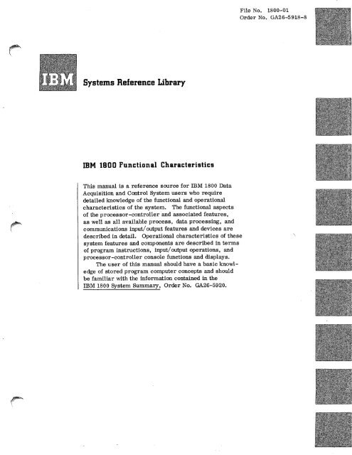
Processor - ControllerCoreStorageOutBusChannel ControlAnalog 774"inputMultiplexerAnalog ToDigitalConverterElectronic"Contact'Operate* Process interrupt statuswords are grouped withdigital inputs because<strong>the</strong> area code is <strong>the</strong>same.ProcessInterrupt(StatusWords)Voltage/ContactSensePulseOutputRegisterOutputDigital ToAnalogConverterDigitalAndAnalogOutputPoints1816Printer -Keyboard1442Cord ReadPunch2401/2402MagneticTape Unit1810DiskStorage1053Printer1055:PTP h1443 :Printer14527PlotterFigure I. System Data Flow4
Page of GA26-5918-8Revised July 14, 1971By TNL: GN26-0269Core Storage Address NotationBase 10 Base 2 Base 164095 XXXX 1111 1111 1111 OFFF8191 XXXI 1111 1111 1111 1FFF16383 XX11 1111 1111 1111 3FFF24575 X101 1111 1111 1111 5FFF32767 X111 1111 1111 1111 7FFF40959 1001 1111 1111 1111 9FFF49151 1011 1111 1111 1111 BFFF57343 1101 1111 1111 1111 DFFF65535 1111 1111 1111 1111 FFFF4,096WordCoreStorage/0000 /OF FF/1000 /1 FF F/2000 /2FFF/F000 /FFFF8,192WordCoreStorage /0000 /1F FF/2000 /3FFFWraparoundWraparound117811L1WraparoundFigure 2. Address Notationoperation, sequential core storage addresses areused to read instructions from core storage forexecution and during transfer of data to or from corestorage. The core storage address may be increasedor decreased, through <strong>the</strong> full address spectrum(/0000 through /FFFF). Depending on corestorage size, multiple excursions through portionsof core storage or wraparound may occur more thanonce with one pass through <strong>the</strong> address spectrum.Wraparound occurs when <strong>the</strong> first core storage location(/0000) appears contiguous with <strong>the</strong> last corestorage location.Figure 3 illustrates how wraparound occurs foreach core storage size. Note <strong>the</strong> unique differencesin <strong>the</strong> 24,576; 40,960; 49,152; and 57,344 wordmodels.Reserved Storage LocationsSome core storage locations are reserved for exclusiveuse by specific features of <strong>the</strong> processorcontroller.Reserved locations and <strong>the</strong> features <strong>the</strong>yare reserved for are as. follows:Storage Location Feature24,576WordCoreStorage32,768WordCoreStorage40,960 CWordCoreStorage/000049,152WordCoreStorage57,344WordCoreStorage/c000 /FFFF/0000 /3FFF /4000 /5FFF/6000 /7FFF/8000 /BFFF /0000 /DFFF/E000 /FFFF/7FFF /8000 /9FFF/A000 /BFFF/C000 /DFFF/E000 /FFFFWraparoundWraparound/0000 /7FFF/8000 /FFFFWraparoundWraparound/0000 /BFFF /C000 IFFF/E000 /FFFFWraparound/0001 CE interrupt/0002 CE interrupt/0004 Interval timer A/0005 Interval timer B/0006 Interval timer C/0008 - /0022 Interrupt addressesFigure 3. Address Wraparound/FFFF30115C1Processor-Controllers 7
Page of GA26-5918-8Revised July 14, 1971By TNL: GN26-0269DATA REPRESENTATIONThe standard or single precision data word is 16 bitsin length as shown in <strong>the</strong> following illustration. Thesign bit (position 0) is always 0 for positive numbersand 1 for negative numbers. Positive numbers areREGISTERSThe following registers are used in <strong>the</strong> manipulationof data and can be displayed on <strong>the</strong> processorcontrollerconsole. These registers are also useduniquely in specific operations described later.I S IPositive numberl's complementAdd 1Resulting 2's complementI I I I I I I 1 / I I ISingle-precisiondata word formatalways in true binary form, whereas negative numbersare in 2's complement form. The 2's complementof a binary number is defined as its l's complementincreased by one. The 1's complement ofa binary number is <strong>the</strong> number that results byreplacing each 1 in <strong>the</strong> number (including sign) witha 0 and each 0 with a 1. The following exampleillustrates <strong>the</strong> 2's complement procedure.152°117142B 10001101001001100111001011011001111110010110110100Bit positions 1 through 15 of a single precisiondata word represent decimal values of 2 14 through2 0 respectively. Thus <strong>the</strong> largest single precisionpositive number that can be represented is 2 15-1 or32,767 (a sign bit of '0 and l's in all o<strong>the</strong>r bit positions).The largest negative number is -2 15 or-32,768 (a sign bit of 1 and 0's in all o<strong>the</strong>r bit positions).The number zero is represented by all bitsbeing 0. There is no negative zero.A double precision data word, as shown in <strong>the</strong>following illustration, can also be used. The doubleprecision data word consists of 32 bits, extending<strong>the</strong> maximum positive number that canbe representedto 2,147,483,647 (2 31-1) and <strong>the</strong> maximumnegative number to -2,147,483,648 (-2 31). Twoadjacent words in core storage must be used, with<strong>the</strong> leftmost word at an even address and <strong>the</strong> rightmostword at <strong>the</strong> next sequential (odd) address.Index RegistersThree index registers (XR) are standard features of<strong>the</strong> processor-controller. The XR's are addressedby <strong>the</strong> tag bits (positions 6 and 7) of an instruction asfollows:Tag Bits XR01 110 211 3Operations on an XR, such as load, store, or modify,are accomplished through instructions in <strong>the</strong> basicinstruction set. The contents of an XR or of <strong>the</strong>instruction register (I) are usually used to performaddress modification.Storage Address Register<strong>All</strong> processor-controller references to storage areunder direct control of <strong>the</strong> storage address register(SAR). Data channel references to storage are undercontrol of <strong>the</strong> channel address register (CAR) for <strong>the</strong>active data channel. (See "Data Channel Control.")Instruction RegisterThe instruction (I) register has 16 positions andholds <strong>the</strong> address of <strong>the</strong> next instruction to be executed.The contents of <strong>the</strong> I-register are automaticallyincreased for sequential operation of instructions.Storage Buffer Register0 1 15 0 15WordI SI I I lErn.W°n1 I t.1 1 1 It I I Odd d iiiiii312Double-Precision Data Word Format 2°1171440The 16-bit storage buffer register (B) is used forbuffering all word transfers with core storage.<strong>All</strong> data enters or leaves core storage via <strong>the</strong>B-register.8
Page of GA26-5918-8Revised July 14, 1971By TNL: GN26-0269Arithmetic Factor RegisterThe 16-bit arithmetic factor register (D) is used tohold one operand for arithmetic and logical operations.The accumulator provides <strong>the</strong> o<strong>the</strong>r factor.AccumulatorThe accumulator (A) is a 16-bit register that contains<strong>the</strong> results of any arithmetic operation. It canbe loaded from or stored into core storage, shiftedright or left, and o<strong>the</strong>rwise manipulated by specificarithmetic and logical instructions.Contents of <strong>the</strong> accumulator are changed bysome instructions that do not indicate specificaccumulator operations.Accumulator ExtensionThe accumulator extension (Q) is a 16-bit low-orderextension of <strong>the</strong> accumulator. It is used duringmultiply, divide, shifting, and double precisionarithmetic.Shift Control CounterThis six-bit counter is used primarily to controlshift operations.Temporary AccumulatorThe temporary accumulator (U) is a 16-bit registerused to save <strong>the</strong> contents of <strong>the</strong> accumulator while<strong>the</strong> accumulator is being used for o<strong>the</strong>r operationssuch as effective address generation.Operation Code RegisterThe five-bit operation code register (OP) is used tohold <strong>the</strong> operation code portion of an instruction.ARITHMETIC OPERATIONSThe arithmetic operations of <strong>the</strong> processor-controllerinclude add, subtract, multiply, and divide.Negative data is always stored and operated upon in2's complement form. Addition and subtraction canbe done in single or double precision. Multiplicationoperates on two single precision words to produce adouble precision product. Division allows <strong>the</strong> dividendto be double precision and uses a single precisiondivisor to produce a single precision quotientand a single precision remainder.Overflow and Carry IndicatorsThe two indicators associated with <strong>the</strong> accumulatorare overflow and carry. The overflow indicator canbe turned on by add, subtract, or divide operations,and indicates a result larger than what can be representedin <strong>the</strong> accumulator. The overflow indicatorcan also be turned on by a load status instruction.Once <strong>the</strong> overflow indicator is on, it cannot bechanged except by testing <strong>the</strong> indicator or by executinga load status or store status instruction.The carry indicator provides <strong>the</strong> informationthat a carry from or borrow by <strong>the</strong> high-order positionof <strong>the</strong> accumulator has occurred. The carryindicator is dynamic and changes with each add orsubtract operation. The carry indicator is alsoaffected by shift left, load status, store status, andcompare instructions.INSTRUCTION FORMATSTwo basic instruction word formats, shown in Figure4, are used in <strong>the</strong> 1800 system. The bits within <strong>the</strong>instruction words are used in <strong>the</strong> following manner:OP (Operation Code): These five bits define whichoperation is to be performed by <strong>the</strong> processorcontroller.F (Format): This bit controls <strong>the</strong> instruction wordformat. When F is 0, <strong>the</strong> instruction is a singleword in length and is referred to as a short instruction.When F is 1, <strong>the</strong> instruction is two words inlength and is referred to as a long instruction.T (Tag): These two bits specify <strong>the</strong> base register (anindex register, <strong>the</strong> instruction register, or addressportion of a long instruction) used in address modification,or <strong>the</strong> location (an index register or displacement)of <strong>the</strong> shift count.DISP (Displacement): During address modification,<strong>the</strong>se eight bits are usually added to <strong>the</strong> instructionOne-Word Instructiono 4 5 9 15Op Code I 1: I .DisplacementF ITwo-Word InstructionO 4 5 8 9 10 15 0I , Op IF I T IAN Condition! I , , Address IFigure 4. Instruction Formats15Processor-Controllers 9
egister or <strong>the</strong> index register specified by <strong>the</strong> tagbits. The modified address is defined as <strong>the</strong> effectiveaddress (EA). (See "Effective AddressGeneration" in this section.)If negative, <strong>the</strong> displacement is in 2's complementform, with <strong>the</strong> sign in bit position 8. The signis automatically extended to <strong>the</strong> higher-order bits(0 through 7) when <strong>the</strong> displacement is used in EAgeneration, or as an add-to-core-storage operand.IA (Indirect Address): This bit is used only in longinstructions. If IA is 0, addressing is direct. IfIA is 1, addressing is indirect. Indirect addressingis explained under "Effective Address Generation"in this section. (See load index and modify indexand skip instructions for exceptions.)Op "F T DipDirect Addressing Indirect AddressingF=0 F=1, IA=0 F=1, IA=1T=00T=01T=10T=11EA= I+DISPEA=XR1+DISPEA=XR2+DISPEA=XR3+DISPEA=AddrEA=Addr+XR1EA=Addr+XR2EA=Addr+XR3EA=V in CSL at AddrEA=V in CSL at "Addr+XR1"EA=V in CSL at "Addr+XR2"EA=V in CSL at ''Addr+XR3"CSL = Core storage locationV = Value4 8 15- Specifies index register (XR), instruction register (I)I or DISP0-One-word instructionBO (Branch Out): This bit is used with store status,branch or skip on condition, and modify index andskip instructions. Refer to <strong>the</strong> individual instructionsfor <strong>the</strong> functions of this bit.Op4 8 9 10 15 0 5FTBIA0Cond[11,1- 0 — Direct addressing1 — Indirect addressing1- Two-word instructionAddrCOND (Condition): These bits specify <strong>the</strong> conditionsthat are interrogated during a BSC or BSI instruction.Figure 5. Effective Address Generation117859ADDRESS: These 16 bits usually specify a corestorage address in a long instruction. The contentsof <strong>the</strong>se bits can be used in effective address generation.EFFECTIVE ADDRESS GENERATIONThe location of a single or double precision wordreferred to in an instruction is denoted by an address.Most program instructions tell <strong>the</strong> processor-controllerto obtain data at a specified addressand perform a certain operation on it. Theversatility of <strong>the</strong> processor-controller allows <strong>the</strong>address in <strong>the</strong> instruction being executed to be modifiedas <strong>the</strong> specific occasion requires. This modifiedaddress is called <strong>the</strong> effective address.The effective address (EA) is developed asshown in Figure 5 for most instructions. Exceptionsare noted in <strong>the</strong> "Instruction Set" section.PROCESSOR-CONTROLLER DATA FLOWAs shown in Figure 6, all instructions and dataentering and leaving core storage do so via <strong>the</strong> B-register. Input devices send data and instructionsto <strong>the</strong> B-register via <strong>the</strong> in bus. Output devicesreceive data from <strong>the</strong> B-register via <strong>the</strong> out bus.As each stored program instruction is selected, itsvarious parts (Op code, format bit, etc.) are directedto <strong>the</strong> control registers via <strong>the</strong> B-register and <strong>the</strong>out bus. The control registers decode and interpreteach instruction before <strong>the</strong> instruction is executed.Except for data channel operations (see "I/OControl" section), all instructions and data mustfirst be addressed by <strong>the</strong> storage address register(SAR) before leaving core storage. SAR obtains <strong>the</strong>core storage address from <strong>the</strong> I-register or <strong>the</strong> A-register. The contents of <strong>the</strong> I-register are developedby one of <strong>the</strong> following methods, depending onprocessor-controller operation.1. The I-register is incremented for each instructionduring sequential operation of <strong>the</strong> storedprogram instructions.2. The effective address of each instruction isdeveloped in <strong>the</strong> accumulator and <strong>the</strong>n transferredto SAR. The contents of <strong>the</strong> accumulatorare saved in <strong>the</strong> U-register during effectiveaddress computation. If <strong>the</strong> instruction is abranch, <strong>the</strong> contents of SAR are transferred to<strong>the</strong> I-register.Each word in core storage consists of 18bits: 16 data bits, a parity bit (P), and a storageprotect bit (5). During an operation, <strong>the</strong> P-bit is10
Core Storage(May be located in P-C or 1803)ddSARe1151IntervalTimersOperationMonitorh.BusConnected toInput DevicesConnected toOutput Devices* Temporary storage for <strong>the</strong> accumulatorControl Registers117391 C IFigure 6. Processor-Controller Data Flowautomatically added or removed to maintainodd parity. The S-bit is added or removed by<strong>the</strong> store status instruction, depending on whe<strong>the</strong>ra "read only" condition is desired in <strong>the</strong>core storage position. The 16 data bits enteror leave core storage via <strong>the</strong> B-register. TheP- and S-bits do so via individual latches. Thelatches and <strong>the</strong> B-register toge<strong>the</strong>r make possible<strong>the</strong> transfer of 18 bits to and from corestorage.The in bus and <strong>the</strong> out bus each include 16 datalines and two parity lines. This line combinationpermits 18-bit transfers to devices such as magnetictape units.DATA FLOW EXAMPLESThe following three examples illustrate <strong>the</strong> data flowfor <strong>the</strong> load accumulator instruction. An examplefor each type of addressing (short format; long format,direct addressing; long format, indirect addressing)is included. The circled numbers in eachillustration correspond to <strong>the</strong> numbered items includedfor that illustration.Processor-Controllers 11
Short InstructionDDOne WordInstructionDataWord11. SAR addresses data word.12. Data word transfers to B-register.13. B-register loads into A-register (through D-register).Long Instruction, Direct Addressing—ARESSINGSARB-Registerlst Word of 2nd Word of DataInstruction Instruction WordDD100E___JI-Registero S S N G(D• .000SARB-Register0D-RegisterOut BusA-RegisterControlRegistersI-RegisterIndexRegister29072A I•Out BusInstruction Cycle1. A-register transfer to U-register.2. I-register transfers to SAR. (I-register contentsare <strong>the</strong>n increased by 1).3. SAR addresses <strong>the</strong> core storage location containing<strong>the</strong> instruction.4. Core storage location transfers to <strong>the</strong> B-registerand out-bus.5. Control registers store various parts of <strong>the</strong>instruction (Op code, format bit, and tag bits).6. Displacement is stored in <strong>the</strong> D-register.7. a. If tag = 00, I-register transfers to A-register.b. If tag 00, <strong>the</strong> specified XR transfers toA-register.8. Displacement (D-register) is added to A-register.Execute Cycle9. A-register transfers to SAR (effective address).10. U-register transfers to A-register.D-RegisterInstruction Cycle 1000IndexRegisterControlRegisters02907M I1. A-register transfers to U-register.2. I-register transfers to SAR. (I-register contentsare <strong>the</strong>n increased by 1.)3. SAR addresses <strong>the</strong> first word of <strong>the</strong> instruction.4. First word of <strong>the</strong> instruction transfers to B-register and out bus.5. Control registers store various parts of <strong>the</strong>instruction (Op code, format bit, and tag bits).6. If tag 00, <strong>the</strong> specified XR transfers to A-register.12
Instruction Cycle 27. I-register transfers to SAR. (I-registercontents are <strong>the</strong>n increased by 1. )8. SAR addresses second word of instruction.9. Second word of instruction (address) transfersto B-register.10. Address (from B-register) is stored in D-register .11. a. If tag = 00, D-register transfers to A-register .b. If tag / 00 , D-register is added to A-register .(A-register contains contents of XR.)0 U-Register RegisterIndexOInstruction Cycle 1Execute CycleInstruction Cycle 2Long Instruction, Indirect Addressing1st Word of 2nd Word of Indirect DataInstruction Instruction Address Word WordRESS N GSARB-Reg sterI-RegisterOut7---7BLD-RegisterExecute CycleControlRegisters OA-R gister 11 17 20--I t129074A }12. A-register transfers to SAR (effective address).13. U-register transfers to A-register.14. SAR addresses data word at effective address.15. Data word transfers to B-register.16. B-register loads into A-register (through D-register).1. A-register transfers to U-register.2. I-register transfers to SAR. (I-registercontents are <strong>the</strong>n increased by 1.)3. SAR addresses first word of <strong>the</strong> instruction.4. First word of instruction transfers to <strong>the</strong> B-register and out bus.5. Control registers store various parts of<strong>the</strong> instruction (Op code, format bit, andtag bits).6. If tag / 00, <strong>the</strong> specified XR transfers to A-register.7. I-register transfers to SAR. (I-register contentsare <strong>the</strong>n increased by 1.)8. SAR addresses second word of instruction.9. Second word of instruction (address) transfersto B-register.10. Address (from B-register) is stored in D-register .11. a. If tag = 00, D-register transfers toA-register.b. If tag / 00, D-register is added to A-register. (A-register contains contentsof XR).Indirect Addressing Cycle12. A-register transfers to SAR.13. SAR addresses core storage location at address(or address + XR).14. Core storage location transfers to B-register.15. B-register transfers to A-register (throughD-register).16. A-register transfers to SAR.17. U-register transfers to A-register.18. SAR addresses data word at effective address.19. Data word transfers to B-register.20. B-register transfers to A-register (throughD-register).Processor-Controllers 13
Instruction SetThe 1800 system instruction set is divided into fiveclasses of instructions. Figure 7 shows <strong>the</strong> class,name, indirect addressing capability, and mnemonicfor each instruction. A more complete breakdownof each instruction, including hexadecimal representationsand assembler language coding examples,is given on <strong>the</strong> page referenced in Figure 7. A summaryof <strong>the</strong> instruction set is given in Appendix Afor quick reference. Instruction execution timesare given at <strong>the</strong> end of this section.Hexadecimal RepresentationoOPF T Disp 15I 1 1 1 1 0 1 1 i 01 01 0 1 01 0 1 1 1 0 1 01 0 1 1 1 0 1 11D 0 4 50 OP F T IA BO Cond 150 Address 151111011,01111,1101010,010[010101010101010101011[11010101111[11117 0 0 0 1 8117152 B1ClassInstructionIndirec tAddressingMnemoni PageLoad and Load Accumulator Yes LD 16Store Load Double Yes LDD 17Store Accumulator Yes STO 18Store Double Yes STD 19Load Index ** LDX 20Store Index Yes STX 21Load Status No LDS 24Store Status Yes STS 23Arithmetic Add Yes A 25Add Double Yes AD 26Subtract Yes 5 27Subtract Double Yes SD 28Multiply Yes M 29Divide Yes D 30AND Yes AND 31OR Yes OR 32Exclusive OR Yes FOR 33ShiftShift Left InstructionsShift Left Logical (A) * No SLA 34Shift Left Logical (AQ)* No SLT 35Shift Left and Count (AQ)* No SLC 37Shift Left and Count (A) * No SLCA 36Shift Right InstructionsShift Right Logical (A)* No SRA 38Shift Right Arithmetically (AQ)* No SRT 39Rotate Right (AQ)* No RTE 40Branch Branch and Store I Yes BSI 43Branch or Skip on Condition Yes BSC(BOSC) 41Modify Index and Skip*. MDX 45Wait No WAIT 47Compare Yes CMP 48Double Compare Yes DCM 49I/O Execute I/O Yes X10 50* Letters in paren<strong>the</strong>ses indicate registers involved in shift operations.** See <strong>the</strong> section for <strong>the</strong> individual instruction (MDX and LDX).Figure 7. Instruction Set17151EThe hexadecimal representation(s) of each instructionis given with its format(s) and assemblerlanguage coding examples. As shown in <strong>the</strong> precedingexample, <strong>the</strong> hexadecimal number is derived bydividing each word of <strong>the</strong> instruction into groups offour bits each, and assigning a hexadecimal valuecorresponding to <strong>the</strong> binary coded decimal (BCD)value of each group.Description SymbologySymbols are used in <strong>the</strong> descriptions and examplesfor <strong>the</strong> instruction. The symbols and <strong>the</strong>ir meaningsare as follows:SymbolMeaningAAccumulatorAccumulator extensionAddr Contents of address portion of atwo-word instructionC SL Core storage locationDisp Contents of displacement portionof a one-word instructionEA Effective address (see Figure 5)EA+1 Next higher address from <strong>the</strong>effective addressIContents of <strong>the</strong> instruction (I)registerVValueXR1 Contents of index register 1XR2 Contents of index register 2XR3 Contents of index register 3Hexadecimal value (can be 0-F)14
Symbol MeaningUsed for hexadecimal values thathave limits. Limits are given wi<strong>the</strong>ach instruction.Assembler Language Coding ExamplesAssembler language coding examples are providedwith each instruction to illustrate <strong>the</strong> relationshipbetween <strong>the</strong> assembler language coding and <strong>the</strong>actual machine language instructions. No attempt ismade to explain or define all aspects of assemblerlanguage programming. Refer to <strong>IBM</strong> 1800 AssemblerLanguage, Order No. GC26-5882, for assemblerlanguage information.The assembler language coding examples forshort instructions in this section are shown with <strong>the</strong>label DISP in <strong>the</strong> operand field. Note that with ashort instruction in which an index register is notspecified, <strong>the</strong> operand may reference a relocatablelabel. However, <strong>the</strong> label must be located within-128 or +127 words of <strong>the</strong> referencing instruction.With a short instruction in which an index registeris specified, <strong>the</strong> operand must be an absolute valueor a computed absolute value. (A computed absolutedvalue is a relocatable value minus ano<strong>the</strong>r relocatablevalue.)Instruction Set 15
LOAD ACCUMULATOR (LD)FORMATS oitamwo.oPritz0 OP F T Disp15 0 OP F T I A B O Cond 15 0Address 15I 1 i 1101010111 I I ol o lo lo lo to iolC 0-3 X XC 4-7 0 or 8 0 X X X X117153 81mom:DESCRIPTIONThe accumulator (A) is loaded with <strong>the</strong> contents of <strong>the</strong>core-storage location specified by <strong>the</strong> effective address(EA) of <strong>the</strong> instruction. The contents of <strong>the</strong> core-storagelocation are unchanged.THE CARRY AND OVERFLOW INDICATORS are notchanged by this instruction.EXAMPLESAssembler Language CodingEquivalent Machine Language InstructionLabel21 25Operation27 30FT323335 40SeeNoteHexadecimalValueDescription, , I LID1 I D,I I S ,P, I I 1 1 COXX Contents of CSL at EA (I + DISP) are loaded into A, 1 I LID, 1 I D,I,S,P, , I C IXX Contents of CSL at EA (XR I + DISP) are loaded into AI I L I D, 2 DJ 1 S,P, 1 C2XX Contents of CSL at EA (XR2 + D1SP) are loaded into Ai l LID1 I 3 D,I,S,P, , C3XX Contents of CSL at EA (XR3 + DISP) are loaded into A1 1 I LID! I L A,D,D1R, 1 1 , 1 C400XXXX Contents of CSL at EA (Addr) are loaded into A1 1 I LID, 1 L I A,D,D,R, , I C500XXXX Contents of CSL at EA (Addr + XR I) are loaded into A1 1 I L,D, L 2 A ID ,D ,R, I 1 1 C600XXXX Contents of CSL at EA (Addr + XR2) are loaded into AI t I LID, L 3 A.D1D IR1 , I C700XXXX Contents of CSL at EA (Addr + XR3) are loaded into A1 1 I LiD, I A,D,D,R,I I— C480XXXX Contents of CSL at EA (V in CSL at Addr) are loaded into A1 1 I LID 1 I I A,D.D,R1,C580XXXX Contents of CSL at EA (V in CSL at "Addr + XR I") are loaded1 1 1 1 I 1 1 1 1 1 I 1 into A, 1 L,D, I 2 A,D,O,R, IC680XXXX Contents of CSL gA (V in CSL at "Addr + XR2") are loadedI 1 I I I I 1 , 1 1 1 1 into A1 1 1 LID, I I 3 A,D,D,R, , C780XXXX Contents of CSL at EA (V in CSL at "Addr + XR3") are loadedI I I i i I I i i i I I I into AFormatShortInstructionLongInstructionDirectAddressingLongInstructionIndirectAddressing16LD
LOAD DOUBLE (LDD)FORMATS0 OP F T Disp 15 0 OPIF T AO Cond 15 0 Address11 1 °I ° I 1 1°1 I I 1 I I I I I 1C 8-B X X110 1 0 1 0 1 1111 I I 1010 1 0 1 0 1 0 1 0,01 IIIC C-F 0 or 8 0 X X X XDESCRIPTIONThe accumulator (A) and its extension (Q) are loadedwith <strong>the</strong> contents of <strong>the</strong> core-storage location specifiedby <strong>the</strong> effective address (EA) of <strong>the</strong> instruction and <strong>the</strong>next higher core-storage location (EA + 1), respectively.This provides double-precision load for use with doubleprecisionarithmetic. The EA of <strong>the</strong> instruction must bean even address in order for <strong>the</strong> instruction to perform asdescribed. If <strong>the</strong> EA is odd, A and Q are both loaded with<strong>the</strong> contents of <strong>the</strong> core-storage location specified by <strong>the</strong>EA. In any case, <strong>the</strong> contents of <strong>the</strong> core-storage locations jare unchanged.THE CARRY AND OVERFLOW INDICATORS are notchanged by this instruction.Assembler Language CodingEquivalent Machine Language Instruction21Label25Operation27 30FT323335 40SeeNoteHexadecimalValueDescriptionFormati 1 LIDID1 D,I1S IP, I I 1 I C8XX Contents of CSL at EA (1 + DISP) and EA + I are loadedi 1 1 11 1 1 1 1 1 I I i i into A and Q1 1 1 L,D 1 D, I D,I,S,P, 1 1 C9XX Contents of CSL at EA (XR1 + DISP) and EA + I are loaded1 1 1 1 I 1 I 1 I I 1 1 into A and Q1 , 1 LIDID1 2 D,I■S,P, . I CAXX Contents of CSL at EA (XR2 + DISP) and EA + 1 are loaded1 i I 1 1 1 i 1 I I into A and QShortInstructioni 1 I L,DIDI 3 DIIISPI 1 I I CBXX Contents of CSL at EA (XR3 + DISP) and EA + I are loaded1 1 I 1 1 1 1 1 1 1 1 1 I into A and Q, , I L,D,D, L POOR , I CCOOXXXX Contents of CSL at EA (Addr) and EA + 1 are loaded intoI I I 1 i 1 1 1 1 1 1 1 1 1 A and QI I 1 LIDID1 L I AID IDIR1 1 1 1 1 CDOOXXXX Contents of CSL at EA (Addr + XR I) and EA + I are loaded1 1 1 1 I 1 I I I I I into A and QI 1 1 L,D,D, L 2 AIDIDIR1 1 1 CEOOXXXX Contents of CSL at EA (Addr + XR2) and EA + 1 are loadedI 1 1 i i 1 1 1 1 1 1 1 1 into A and QLongInstructionDirectAddressing1 1 L,D,D, L 3 A,D,D,R, 1 CFOOXXXX Contents of CSL at EA (Addr + XR3) and EA + 1 are loadedI I I 1 1 1 !III I I i into A and QI I I L,D,D, I A,D,D,R, 1 I CC80XXXX Contents of CSL at EA (V in CSL at Addr) and EA + 1 are1 1 I i 1 1 1 1 1 1 1 I I 1 loaded into A and Qi 1 L,D,D, I I AiD,D1R1 1 1 CD8OXXXX Contents of CSL at EA (V in CSL at "Addr + XR1") and EA + 11 1 I i I 1 1 1 1 1 I I are loaded into A and Qi 1 L,D,D, I 2 AID ID,R, i CE80XXXX Contents of CSL at EA (V in CSL at "Addr + XR2") and EA + I1 i 1 i 1 1 I 1, 1 I 1 are loaded into A and Q1 , L,D,D, 13 A,D,D,R, 1 CF80XXXX Contents of CSL at EA (V in CSL at "Addr + XR3") and EA + 11 I 1 i 1 1 1 1 I 1 1 1 I 1 are loaded into A and QLongInstructionIndirectAddressingInstruction Set 17LDD
STORE ACCUMULATOR (STO)FORMATSF 0 OP T Disp 150 OP F T IA BO Coed 15 0 Address 151 1 1 1 1 0 1 1 1 0 1 0 11 I 1, 1 1 1 1 1 I1 1[1101110111 I I 1010,010,010,01 I ►D 0-3 X XD 4-7 0 or 8 0 X X X X117155 BIDESCR IPTIONThe contents of <strong>the</strong> accumulator (A) are stored in <strong>the</strong>core-storage location specified by <strong>the</strong> effective address(EA) of <strong>the</strong> instruction. The contents of A are unchanged.THE CARRY AND OVERFLOW INDICATORS are notchanged by this instruction.21Label25Assembler Language CodingOperation27 30FT322335 40SeeNoteHexadecimalValueEquivalent Machine Language InstructionDescription1 1 1 SITIO! D,I 1 SIP1 I I I I DOXX Contents of A are stored in CSL at EA (I + DISP)1 1 I SIT 101 1 D,I / S,P, I I 1 i D IXX Contents of A are stored in CSL at EA (XR1 + DISP)L I I I SITIO! 2 DJ ,S 11) 1 D2XX Contents of A are stored in CSL at EA (XR2 + DISP)I 1 S IT I O, 3 D,I 1 S p, 1 1 D 3XX Contents of A are stored in CSL at EA (XR3 + DISP)1 1 1 SITIO, L A,D,D,R, 1 1 t 1 D400XXXX Contents of A are stored in CSL at EA (Addr)I I I I S,T,O 1 L 1 A in ,D 1R1 I I , I D500XXXX Contents of A are stored in CSL at EA (Addr + XR1)__ 1 1 SIT,01 L 2 AID ID 1R1 I D600XXXX Contents of A are stored in CSL at EA (Addr + XR2)1( 1 StTIOI L 3 AD IDA! I I 1 I D700XXXX Contents of A are stored in CSL at EA (Addr + XR3)I 1 I S,T10, I A,DID RI I I I I D480XXXX Contents of A are stored in CSL at EA (V in CSL at Addr)I I I I SITIO, I I AID IDIR1 1 I I I D580XXXX Contents of A are stored in CSL at EA (V in CSL atI I I I 11 I 1 I 1 I I "Addr + XR I")I I S IT XL I 2 A,D ,D ,R, I D68OXXXX Contents of A are stored in CSL at EA (V in CSL atI I I I I I t I II I I I I "Addr + XR2")t 1 I S,T 10, I 3 AD ID ,R, I I 1 1 D780XXXX Contents of A are stored in CSL at EA (V in CSL at1 1 1 1 1 1 1 1 1 1 "Addr + XR3")FormatShortInstructionLongInstructionDirectAddressingLongInstructionIndirectAddressing18STO
STORE DOUBLE (STD)memo FORMATS L0 OPF T I A B O Cond15 0 Address15( 1 1 1 1 0 11 1 1 1 1 .11 0 1. 0,0 1 0 1 0 1 0 1 0 1 1 1 I 1 1 1 I 1 1 1 1 1 1 1 1D C—F 0 or 8 0 X X X X117156 BIDESCR IPTION.W°775.WW1.-The contents of <strong>the</strong> accumulator (A) and its extension(Q) are stored in <strong>the</strong> core-storage location specified by<strong>the</strong> effective address (EA) of <strong>the</strong> instruction and <strong>the</strong>next higher core-storage location (EA + 1), respectively.This provides double-precision store for use with doubleprecisionarithmetic. The EA of <strong>the</strong> instruction must bean even address in order for <strong>the</strong> instruction to perform asdescribed. If <strong>the</strong> EA is odd, <strong>the</strong> contents of A are storedat <strong>the</strong> EA and <strong>the</strong> contents of Q are not stored. In anycase, <strong>the</strong> contents of A and Q remain unchanged.THE CARRY AND OVERFLOW INDICATORS are notchanged by this instruction.EXAMPLES VR.M.,1,7NVOBE:rATAW111;-'2,;;Q5Assembler Language CodingEquivalent Machine Language InstructionLabel21 25Operation27 30FT323335 40SeeNoteHexadecimalValueDescriptionFormat, , SITID, D11 ,S IP, 1 I D8XX Contents of A and Q are stored in CSL at EA (I + DISP) andi 1 , 1 I, , 1 1EA + 11 1 I S IT I D, I DI I IS ,P, 1 1 1 1 D9XX Contents of A and Q are stored in CSL at EA (XR1 + DISP)I [ 1 1 1 I 1 1 1 1 1 1t 1 and EA + 11 S IT I D, 2 D,I,S,P, i DAXX Contents of A and Q are stored in CSL at EA (XR2 + DISP)1 1 i 1 i 1 i 1 i and EA + I, 1 SIT,D1 3 D 1 I,S,P 1 I I 1 DBXX Contents of A and Q are stored in CSL at EA (XR3 + DISP)I I I I I i i I i 1 and EA + 11 1 I S IT ID, L A I D ,D,R, • , DCOOXXXX Contents of A and Q are stored in CSL at EA (Addr) andI ii / 1 i 1 1 1 1 1 EA + 1i , SIT ID, L I A,D ,D,R, 1 DDOOXXXX Contents of A and Q are stored in CSL at EA (Addr + XR I)I I 1 1 1 I 1 1 1 I and EA + 11 1 S,T,D, L 2 A ID ,D,R 1 DE00XXXX Contents of A and Q are stored in CSL at EA (Addr + XR2)1 1 1 1 1 1 1 1 1 1 1 1 1 1 and EA + 11 1 SIT,D, L 3 A,D,D I RI 1 I DFOOXXXX Contents of A and Q are stored in CSL at EA (Addr + XR3)I i I i i i 1 1 1 1 1 1 1 1 and EA + 1I 1 I SITIDI I A,D,D,R, 1 1 I I DC80XXXX Contents of A and Q are stored in CSL at EA (V in CSL at1 1 I 1 1 1 1 1 1 i I I 1 I Addr) and EA + 11 I I S,T,D, I I A,D,D,R, 1 DD80XXXX Contents of A and Q are stored in CSL at EA (V in CSL atI I I I I I t I I I "Addr.+ XR I") and EA + 11 i STD I122 A,D,D,R, , DE80XXXX Contents of A and Q are stored in CSL at EA (V in CSL at. 1 1 1 !III , "Addr + XR2") and EA + 1I t1 DF80XXXX Contents of A and Q are stored in CSL at EA (V in CSL at1 I I I I I III1"Addr + XR3") and EA + I',,, S,T,D , I 3 A,D,D,R,ShortInstructionLongInstructionDirectAddressingLongInstructionIndirectAddressingInstruction Set 19STD
LOAD INDEX (LDX)0 OP F T Disp 151 0 1 1 1 1 1 0 1 0101 l 1±1 1 1 1 1 10 OF10,1,1,0,0111 , Iot01010101010I±1 ii 1 if lilt 'ill!6 6 4-7 0 or 8 0 X X X XT = 00 Load I T = 10 Load XR2T = 01 Load XR1 T =11 Load XR3IA = 0 - Load ImmediateIA =1 - Load DirectDESCR IPT IONAn index register (XR) or <strong>the</strong> instruction (I) register isloaded with <strong>the</strong> displacement portion of <strong>the</strong> instruction,<strong>the</strong> address word of <strong>the</strong> instruction, or <strong>the</strong> contents of<strong>the</strong> core-storage location specified by <strong>the</strong> address word.The tag bits indicate which register is loaded. The sourceof <strong>the</strong> data is dependent on <strong>the</strong> instruction format; shortor long. In any case, <strong>the</strong> source of data remains unchanged.IF SHORT FORMAT (F bit is 0), <strong>the</strong> register specified by<strong>the</strong> tag bits is loaded with <strong>the</strong> displacement portion of<strong>the</strong> instruction. Before being loaded, <strong>the</strong> displacementis expanded to a 16-bit word by propagating <strong>the</strong> valueof <strong>the</strong> sign bit (bit position 8 of <strong>the</strong> instruction)to <strong>the</strong> left 8 positions.IF LONG FORMAT (F bit is 1), <strong>the</strong> IA bit of <strong>the</strong> instructionfur<strong>the</strong>r specifies <strong>the</strong> source of data. If <strong>the</strong> IA bit is0, <strong>the</strong> register specified by <strong>the</strong> tag bits is loaded with<strong>the</strong> address word. If <strong>the</strong> IA bit is 1, <strong>the</strong> register specifiedby <strong>the</strong> tag bits is loaded with <strong>the</strong> contents of <strong>the</strong>core-storage location specified by <strong>the</strong> address word.THE CARRY AND OVERFLOW INDICATORS are notchanged by this instruction' Oterkile,IVA,g5WZir,,i4.1,1*Vii5,41-,-*V1.1,X$I.,:gEgrat744e,:;.; e,„ ,Assembler Language CodingEquivalent Machine Language Instruction21Label25Operation27 30FT323335 40SeeNoteHexadecimalValueDescriptionFormat, , , L1D,X, MIS1P1 1 1 1 l 60XX Load expanded DISP into instruction register1 1 I LID, X, I D,I,S,P, 61XX Load expanded DISP into index register 11 1 1 L1D1X, 2 DiIiS,P, I I 62XX Load expanded DISP into index register 2, , 1 L,D I X, 3 D,I,S,P, 1 63XX Load expanded DISP into index register 3, , , L 1 D 1X, L A,D,D,R, 1 1 , 6400XXXX Load Addr into instruction registerI I I L 1D,X, L I A,D,D,R, , 1 6500XXXX Load Addr into index register 1, 1 I L,D,X, L 2 A,D,D,R 1 6600XXVC Load Addr into index register 2i , , L1D,X, L 3 A,D,D,R, 16700XXXX Load Addr into index register 3, 1 , L,D,X, I A,D,D,R, , 6480XXXX Load contents of CSL at Addr into instruction register, , L,D,X, I I A,D,D,R,_1 6580XXXX Load contents of CSL at Addr into index register 11 , 1 L,D ,X, 1 2 A,D I D,Ri 6680XXXX Load contents of CSL at Addr into index register 2, , , L,D,X, 1 3 AiD,D,R, , i 6780XXXX Load contents of CSL at Addr into index register 3ShortInstructionLongInstructionDirectAddressingLongInstructionIndirectAddressing20LDX
STORE INDEX (STX)FORMATSOP F T Disp 15 0 OP F T /A BO Cond 15 0 Address151 0,1 1 1 1 0 ,1101 I I, I° 1 1 11 101 I , I lolo I o 1 0 1 0 1 o 1 0 111111111111111116 8-B X XT= 00 Store IT = 01 Store XR1T = 10 Store XR2T = 11 Store XR36 C-F 0 or 8 0 X X X X117160 B1DESCR IPTIONAn index register (XR) or <strong>the</strong> instruction (I) register isstored in <strong>the</strong> core-storage location specified by <strong>the</strong> effectiveaddress (EA) of <strong>the</strong> instruction. The contents of <strong>the</strong>register stored remains unchanged. The tag bits specifywhich register is stored and <strong>the</strong>refore, cannot be used ineffective address generation. The EA for a short instructionis (I + Disp). The EA for a long instruction withdirect addressing (IA bit is 0) is (Addr). The EA for a longinstruction with indirect addressing (IA is 1) is (value incore-storage location at Addr).THE CARRY AND OVERFLOW INDICATORS are notchanged by this instruction.EXAMPLES21Label25Assembler Language CodingOperation27 30FT323335 40SeeNoteHexadecimalValueEquivalent Machine Language InstructionDescription1 1 S,TIX, D,IISIPI 1 I 68XX Store I in CSL at EA (I + DISP), , 1 S,T,X, I D, I ,S,P, 1 1 I 1 69XX Store XR1 in CSL at EA (I + DISP)I t I S I T I X, 2 D,I1S IP, 1 6AXX Store XR2 in CSL at EA (I + DISP)t 1 S,T,X, 3 011,SIPI 1 1 t 1 6BXX Store XR3 in CSL at EA (I + DISP)I . I %TX, L A1D1DIR1 1 1 , 6000XXXX Store I in CSL at EA (Addr), i SIT,X, L I A,D,D,R, , I 6D00XXXX Store XR1 in CSL at EA (Addr)t 1 I S,T,X, L 2 A,D,D,R, 1 6E00XXXX Store XR2 in CSL at EA (Addr), , I S IT,X, L 3 A,D,D,R, 6F00XXXX Store XR3 in CSL at EA (Addr)1 1 S,T,X, I A,D,D,R, , 6C80XXXX Store I in CSL at EA (V in CSL at Addr), , S,T1X1 I I A,D,D,R,I6D80XXXX Store XR I in CSL at EA (V in CSL at Addr)i II S,T,X, I 2 A,D,D,R,1 I6E80XXXX Store XR2 in CSL at EA (V in CSL at Addr), I ST, , X, I A,D,D,R, 1 6F80XXXX Store XR3 in CSL at EA (V in CSL at Addr)FormatShortInstructionLongInstructionDirectAddressing.LongInstructionIndirectAddressingInstruction Set 21STX
STORE STATUS (STS) Store Status FunctionFORMATSOP F T Disp 15 0 OP F T 1A80 Cond 15 0 Address 15I 01011,01110[IIIIIIIIIII 010 1 11011I1I oioo2 8–B X X 2 C–F 0 or 8 0 X X X XDESCR IPTION117162BIThe status of <strong>the</strong> carry and overflow indicators arestored in bit positions 14 and 15, respectively, of <strong>the</strong>core-storage location specified by <strong>the</strong> effective address(EA) of <strong>the</strong> instruction. The carry and overflow indicatorsare <strong>the</strong>n reset. Bit positions 0 through 7 of <strong>the</strong> wordat <strong>the</strong> EA remain unchanged and bit positions 8 through13 are reset to 0's as shown in <strong>the</strong> illustration.If <strong>the</strong> long format is used, bit 9 (BO) of <strong>the</strong> instructionmust be 0 for a store status function; o<strong>the</strong>rwise awrite or clear storage protect bit function is performed0 13 14 IS10 . 0 ,000 ,01 I IUnchangedas described on <strong>the</strong> next page.OverflowCarryNEMTHE CARRY AND OVERFLOW INDICATORS are resetas <strong>the</strong>y are stored.EXAMPLESAssembler Language CodingEquivalent Machine Language Instruction21Label25Operation27 30FT323335 40SeeNoteHexadecimalValueDescriptioni 1 S ,T IS, D,I,SIP,,28XXStore status of indicators in CSL at EA (I + DISP)i , 1 SITISI I D, LS ,P,,29XX Store status of indicators in CSL at EA (XR1 + DISP)1 1 S,TIS, 2 D,I ,S ,P, I 2AXX Store status of indicators in CSL at EA (XR2 + DISP)1 1 SITISI 3 D, I ,S IP, , 2BXX Store status of indicators in CSL at EA (XR3 + DISP), SITIS, L A,D,D,R, , 2C00XXXX Store status of indicators in CSL at EA (Addr)1 1 S ,T ,S, L I A,D,D,R, , 2D00XXXX Store status of indicators in CSL at EA (Addr + XR1)1 1 S1T,S 1 L 2 AID ,D ,R, 1 2EOOXXXX Store status of indicators in CSL at EA (Addr + XR2)I S I-1,S, L 3 A,D 1D ,R, , 2F00XXXX Store status of indicators in CSL at EA (Addr + XR3), i S,T,S, I A,D ,D,R, , 2C80XXXX Store status of indicators in CSL at EA (V in CSL at Addr), , S,TISI I I A,D,D,R,/212/80XXXX Store status of indicators in CSL at EA (V in CSL at "AddrI I 1 1 11 1 1 1I 1+ XR I")1 1 S,T,S, I 2 A,D ,D ,R, , 2E80XXXX Store status of indicators in CSL at EA (V in CSL at "Addri I 1 , , I , 1 1 1 I I 1 I + XR2")I 1 1 S IT,S, I 3 A,D,D,R, , 2F80XXXX Store status of indicators in CSL at EA (V in CSL at "Addr1 11 1 1 1 • 1 1 1 1 1 1 1 1 + XR3")FormatShortInstructionLongInstructionDirectAddressingLongInstructionIndirectAddressing22STS
STORE STATUS (STS) Write or Clear Storage Protect Bit FunctionFORMAT0 OP F T 'A DO Coed 15 0 Address 15, I ijo,o,o,o,o, „ „ I „ , , I I2 C-F 4 or C 0 or 1 X X X X117164 B1DESCRIPTIONThe storage protect bit in <strong>the</strong> core-storage location specifiedby <strong>the</strong> effective address (EA) of <strong>the</strong> instruction iswritten or cleared as indicated by bit position 15 of <strong>the</strong>instruction being 1 or 0, respectively.A long format instruction (F bit is 1) must be usedand bit 9 (BO) of <strong>the</strong> instruction must be 1 for a writeor clear storage protect bit function; o<strong>the</strong>rwise a storestatus function is performed as described on <strong>the</strong> precedingpage.The preceding description of <strong>the</strong> write or clear storageprotect bit function is performed only if <strong>the</strong> write storageprotect bits switch on <strong>the</strong> P-C console is positioned onYES. As long as this switch is on YES, <strong>the</strong> program has<strong>the</strong> ability to write or clear storage protect bits as describedin <strong>the</strong> preceding paragraphs. If <strong>the</strong> switch is onNO, this instruction performs as a no-op (no-operation).THE CARRY AND OVERFLOW INDICATORS are notchanged by this instruction.EXAMPLES714 .12Label21 25Assembler Language CodingOperation27 30FT323335 40SeeNoteHexadecimalValueEquivalent Machine Language InstructionDescription, 1 S Il l s I L A,D,D,R, ,1/14,012C40XXXX Clear storage protect bit in CSL at EA (Addr)I , I MIS, L AA) il) p , , 1/ 1411 ,2C41XXXX Write storage protect bit in CSL at EA (Addr)I 1 I S I T I S, L I A,D,D,R,, ,/ 1 4,0 12D40XXXX Clear storage protect bit in CSL at EA (Addr+XR I)1 i I S IT 'S ., L I A,D,D,R, III 4,1 ,2D4IXXXX Write storage protect bit in CSL at EA (Addr+XR I), , 1 S I T I S, L 2 A,D,D,R 1 , ,/ .4 1 0 1 2E4 OXXXX Clear storage protect bit in CSL at EA (Addr+XR2)1 1 1 S,T,S, L 2 A,D,D,R 1 , 1 / 1 4,1 , 2E41XXXX Write storage protect bit in CSL at EA (Addr+XR2)I I I I S,T,S, L 3 A,D,D,R, , ,/ 1 4 10, 2F40XXXX Clear storage protect bit in CSL at EA (Addr+XR3), , S,T,S, L 3 A,D,D1R1, 1/,41 II 2F41XXXX Write storage protect bit in CSL at EA (Addr+XR3)I 1 S,T,Si I A,D,D,R 1 , ,/,4,0, 2CCOX.XXX Clear storage protect bit in CSL at EA (V in CSL at Addr), , 1 S iT I S, I A,D,D,R, I 1,4 1 I 1 2CCIXXXX Write storage protect bit in CSL at EA (V in CSL at Addr)I i I I I i 1 1 1 1 1 1 1 1I I I S,T,S, I I A,D,D,R, ,1/14,0, 2DCOXXXX Clear storage protect bit in CSL at EA (V in CSL atI 1 1 1 1 I t 1 1 1 1 1 1 1 1"Addr+XR 1")1 i I S,T,S, I I A,D,D,R; ,,/,41112DC1XXXX Write storage protect bit in CSL at EA (V in CSL atI I I I I I 1 1 1 1 I I 11 "Addr+XR I")1 I I S,T,S, I 2 A, D I DR! , ,/,4 10, 2ECOXXXX Clear storage protect bit in CSL at EA (V in CSL atI I I I i I I 1 I 1 1 1 I I I "Addr+XR2")I 1 S,T,S, I 2 A,D,D,R,,,/ ,4, I, 2ECIXXXX Write storage protect bit in CSL at EA (V in CSL atI i i 1 1 1 1 i I I 1 1 1 "Addr+XR2")I 1 I S,T,S, I 3 A,D,D,R, ,,/,4,0, 2FCOXXXX Clear storage protect bit in CSL at EA (V in CSL atI I I I I I i I ii i I t I "Addr+XR3")i 1 SiTIS, 1 3 4,0 1 1),R, , J 1 4,1 1 2FCIXXXX Write storage protect bit in CSL at EA (V in CSL at1 I 1 I 1 I 1 i I "Addr+XR3")A With MPX Version 3, <strong>the</strong> storage protect operand (/40 and /41) can besymbolically represented by U and P, respectively.FormatLongInstructionDirectAddressingLongInstructionIndirectAddressingInstruction Set 23STS
LOAD STATUS (LDS)117165 A1DESCRIPTIONThe carry and overflow indicators are loaded with <strong>the</strong> struction are not changed during execution of <strong>the</strong> instruestatusof bit positions 14 (carry) and 15 (overflow) of tion. This instruction applies to <strong>the</strong> short format only.<strong>the</strong> instruction. A 1 bit sets <strong>the</strong> respective indicator on,and a 0 bit sets <strong>the</strong> respective indicator off. Normally<strong>the</strong> carry and overflow status were previously stored THE CARRY AND OVERFLOW INDICATORS are setin this instruction by a store status instruction. The according to bit positions 14 and 15 of <strong>the</strong> instruction,statuses of bit positions 14 and 15 of <strong>the</strong> load status in- respectively.EXAMPLESumeAssembler Language CodingEquivalent Machine Language InstructionLabel21 25Operation27 30FT323335 40SeeNoteHexadecimalValueDescription1 1 1 1 LID I S I 01 1 I I I I I I 2000 Set carry and overflow indicators off1111 L,D,S, I 1 1 1 1 1 1 1 / 2001 Set overflow on and carry offI 11 I L 1D1 SI 2 111 1 1 1 2002 Set overflow off and carry on1 1 1 1 L 1 0 I S I 31 1 I I I I I I 2003 Set carry and overflow indicator onFormatShortInstruction24LDS
ADD (A)FORMATS0 OP F T Disp 15 0 OP F T I A B O Cond 15 0 Address 150 1 0 1 0,0101 I I I I, 1 1 1 0 10 o,ohl , I JoIDIDIDIDIDIOI, , , „ „ „ , I8 0-3 X X 8 4-7 0 or 8 0 X X X X117167 B1DESCRIPTIONThe contents of <strong>the</strong> core-storage location specified by<strong>the</strong> effective address (EA) of <strong>the</strong> instruction are addedalgebraically to <strong>the</strong> contents of <strong>the</strong> accumulator (A).The sum replaces <strong>the</strong> contents of A, while core storageremains unchanged. Negative operands and/or negativesums are both in 2's complement form. (See "DataAddition" for details of add operations.)THE CARRY INDICATOR is turned on by a carry out of<strong>the</strong> high-order bit position of A during <strong>the</strong> add operation.THE OVERFLOW INDICATOR is turned on if <strong>the</strong> magnitudeof <strong>the</strong> sum is too large to be presented by A; thatis, greater than +32,767 or less than -32,768. (Thiscondition is detected by a resultant carry out of oneand only one of <strong>the</strong> two high-order bit positions ofA.) If <strong>the</strong> overflow indicator is already on, it is notchanged. The overflow indicator can be reset with aload status instruction, store status instruction, or bytesting <strong>the</strong> indicator with a branch or skip on conditioninstruction.EXAMPLES 1111.1'1—Assembler Language CodingEquivalent Machine Language InstructionLabel21 25Operation27 30FT323335 40SeeNoteHexadecimalValueDescription, , I A, I I D,I,S,P, I 1 1 1 80XX Add contents of CSL at EA (I + DISP) to Ai , Ai I I I D,I,S,P, 1 1 1 1 81XX Add contents of CSL at EA (XR1 + DISP) to A1 , 1 A l 11 2 D,I,S,P, 1 1 1 1 82XX Add contents of CSL at EA (XR2 + DISP) to A, I 1 A, I I 3 D,I,S,P, I I , I 83XX Add contents of CSL at EA (XR3 + DISP) to AII 1 I AI I I L A,D,D,R, i I 8400XXXX Add contents of CSL at EA (Addr) to A, I I Ai 1 1 L I A,D,D I R, I I I I 8500XXXX Add contents of CSL at EA (Addr + XRI) to A, I 1 A, L 2 AIDIDIR1 I I I 1 8600XXXX Add contents of CSL at EA (Addr + XR2) to A, , Al L 3 A,D,D,R, I I I 1 8700XXXX Add contents of CSL at EA (Addr + XR3) to AI , 1 A, I A,D,D,R, , 8480/00(X Add contents of CSL at EA (V in CSL at Addr) to AI , , I A, I I A,D,D,R, I I 8580XXIOC Add contents of CSL at EA (V in CSL at "Addr + XR 1") to A, , A, I I I 2 A I D,D,R, I I i I 8680XXX2C Add contents of CSL at EA (V in CSL at "Addr + XR2") to AI , I A, 13 A,DiD,R, I I 8780XXXX Add contents of CSL at EA (V in CSL at "Addr + XR3") to AFormatShortInstructionLongInstructionDirectAddressingLongInstructionIndirectAddressingInstruction Set 25A
Page of GA26-5918-8Revised July 14, 1971By TNL: GN26-0269ADD DOUBLE (AD)FORMATS0 OP F T Disp15 0 OPF T IA BO Cond 15 0 Address 151,0,0,0 1 1111 1 I 101010101010101immillimil18 C-F 0 or 8 0 X X X X11716861Two words - - <strong>the</strong> contents of <strong>the</strong> core-storage locationspecified by <strong>the</strong> effective address (EA) of <strong>the</strong> instruction,and <strong>the</strong> next higher core-storage location (EA + 1)- - areadded algebraically to <strong>the</strong> contents of <strong>the</strong> accumulator (A)and its extension (Q). This provides double-precisionaddition with A and Q considered as one 32-bit accumulator.The sum replaces <strong>the</strong> contents of A and Q,while core storage remains unchanged. Negative operandsand/or negative sums are both in 2's complementform.The effective address (EA) of <strong>the</strong> instruction must bean even address for correct operation. If <strong>the</strong> EA is odd,<strong>the</strong> contents of <strong>the</strong> core-storage location specified by<strong>the</strong> EA are added to both A and Q, and may be addedincorrectly in A.A DESCRIPTION s _ettseivatt+•1=7,vTHE CARRY INDICATOR is turned on by a carry out of 1<strong>the</strong> high-order bit position of A during <strong>the</strong> add operation.THE OVERFLOW INDICATOR is turned on if <strong>the</strong> magnitudeof <strong>the</strong> sum is too large to be represented in A andQ; that is, greater than +2,147,483,647 or less than-2,147,483,648. (This condition is detected by a resultantcarry out of one and only one of <strong>the</strong> two high-orderbit positions of A.) If <strong>the</strong> overflow indicator is alreadyon, it is not changed. The overflow indicator can bereset with a load status instruction, store status instruction,or by testing <strong>the</strong> indicator with a branch or skipon condition instruction.,metvitesseststest __MEWEXAMPLES emusawaszenssamar—mrAssembler Language CodingEquivalent Machine Language Instruction21Label25Operation27 30FT323335 40SeeNoteHexadecimalValueDescriptionFormat1 [ AID! DJ ' SIP, 1 I 88XX Add contents of CSL at EA (I + DISP) and EA + 1 to A and Qt I I AID, I DJ ,SIP, , 89XX Add contents of CSL at EA (XR I + DISP) and EA + 1 to A and1 [ I I I I III III Q1 I AID, 2 D,I,S,P, I 8AXX Add contents of CSL at EA (XR2 + DISP) and EA + I to A andi I I I I I II il 1 1 . 1 Q1 I I A I D, 3 D,I ,S,P, , I 8BXX Add contents of CSL at EA (XR3 + DISP) and EA + Ito A and1 1 I 1 1 I I I I I I 1 1 I Q, , A, D, L A,D,D,R, , 8C00XXXX Add contents of CSL at EA (Addr) and EA + 1 to A and 0, I I A,D, L I A,D,DIRI i 8D00XXXX Add contents of CSL at EA (Addr + XR I) and EA + 1 to A and/ 1 I / I 1 1 1 1 1 1 1 1 Qt I AID, 2 A,D,D,R, , I 8EOOXXXX Add contents of CSL at EA (Addr + XR2) and EA + 1 to A andI I I 1 1 1 1 1 1 1 1 1 1 Q1 1 A,D, L 3 A,D,D,R 8F00XXXX Add contents of CSL at EA (Addr + XR3) and EA + 1 to A andI I 1 1 1 III 1 Q1 1 1 A,D, I I &MR 1 1 i 8C80XXXX Add contents of CSL at EA (V in CSL at Addr) and EA + I toI 1 I 1, 1 11 I I A and Q1 1 1 A,D, I I A I D,D,R, 1 1 i l 8D80XXXX Add contents of CSL at EA (V in CSL at "Addr + XR1") andt, 1 I, 1 Mt t 1 EA+1 toAandQ1 1 A, D I 2 A,D,D,R, 1 1 8E80XXXX Add contents of CSL at EA (V in CSL at "Addr + XR2") and1 I 1 1 I 1 1 1 i 1 1I EA+ 1 toAandQ1 I A,D, 1 3 A,D,D,R, 1 I I 8F80XXXX Add contents of CSL at EA (V in CSL at "Addr + XR3") and1 1 1 1 1 1 Ili' 1 1 I EA+ItoAandQShortInstructionLongInstructionDirectAddressingLongInstructionIndirectAddressing26AD
SUBTRACT (S)11 FORMATS _IOP F T Disp 101 10 10 11 10 1 0 1 1 I I 1 1 1 1 1 1 I0 OP F T IA BO Cond 15 0 Address 15I I 1 0 / 0 1 1 ICH I 1°1 0 1°1°1°1°1 01 11 1 1 l 1 1 1 1 1 1 1 1 l 1 I9 0-3 X X 9 4-7 0 or 8 0 X X X X117169 BT DESCRIPTION rThe contents of <strong>the</strong> core-storage location specified by<strong>the</strong> effective address (EA) of <strong>the</strong> instruction are subtractedalgebraically from <strong>the</strong> contents of <strong>the</strong> accumulator(A). The difference replaces <strong>the</strong> contents of A, whilecore storage remains unchanged. Negative operands and/or negative differences are both in 2's complement form.THE CARRY INDICATOR is turned on if a borrow by <strong>the</strong>high-order bit position of A occurs during <strong>the</strong> subtractoperation.THE OVERFLOW INDICATOR is turned on if <strong>the</strong> magnitudeof <strong>the</strong> difference is too large to be represented inA; that is, greater than +32,767 or less than -32,768.(This condition is detected by a borrow from one and onlyone of <strong>the</strong> two high-order bit positions of A.) If <strong>the</strong> overflowindicator is already on, it is not changed. The overflowindicator can be reset with a load status instructionor store status instruction, or by testing <strong>the</strong> indicatorwith a branch or skip on condition instruction.Assembler Language CodingEquivalent Machine Language Instruction21Label25Operation27 30FT323335 40SeeNoteHexadecimalValueDescriptionI I SI I I D,I ,S,P, I 1 i 90XX Subtract contents of CSL at EA (I + DISP) from Ai I SI 1 I I D I I,S,P, I I I I91XXSubtract contents of CSL at EA (XR 1+ DISP) from AI 1 I I S, I I 2 D,I LS ,P, 1 1 i 192XX Subtract contents of CSL at EA (XR2 + DISP) from AS I I I 3 D,I,S,P, I 93XX Subtract contents of CSL at EA (XR3 + DISP) from AFormatShortInstructionI I , I S i I L A,D,D,R, I , 9400XXXX Subtract contents of CSL at EA (Addr) from A Long11 I SI I 1 L I A,D,,R, DI I I 9500XXXX Subtract contents of CSL at EA (Addr + XR I) from AInstructionDirectI 1 I S l 1 L 2 A,D,D,R, 1 9600XXXX Subtract contents of CSL at EA (Addr + XR2) from AAddressingI I I S, , 1 L 3 A,D,D,R1 1 I i I 9700XXXX Subtract contents of CSL at EA (Addr + XR3) from AI I 1 Sl 1 I I A,D,D,R, I I 9480XXXX Subtract contents of CSL at EA (V in CSL at Addr) from A1 I I St i 1 I I A,D,D,R, I 1 1 19580XXXX Subtract contents of CSL at EA (V in CSL at "Addr + XR1")I I I 1 I I 1 1 1 11 11from AI I S I 1 I 2 A,D,D,R, , 9680XXXX Subtract contents of CSL at EA (V in CSL at "Addr + XR2")I 1 I I I I 1 I I 1 1 I I I from AI 1 I I S1 I I I 3 A,D,D1R1 1 I 9780XXXX Subtract contents of CSL at EA (V in CSL at "Addr + XR3")1 1 1 1 1 1 I 1 1 1 11 1 1 from ALongInstructionIndirectAddressingInstruction Set 27S
SUBTRACT DOUBLE (SD).fartzaielTmEasanuenta.mFoRmATsF T Disp 150 OPF T I A B O Cond15 0Address 15I l 10101111101 I I 1 1 1 I I 1 I9 8-B X X1 1 1 0 1 0 1 11 1 1 1 1 1 1 1°1°1 0101010I I I I I I I 1 I I 1 I I I I I9 C-F 0 or 8 0 X X X X117170 B]MEM 'rDESCRIPTION'Two words - - <strong>the</strong> contents of <strong>the</strong> core-storage locationspecified by <strong>the</strong> effective address (EA) of <strong>the</strong> instruction,and <strong>the</strong> next higher core-storage location (EA +1) - - aresubtracted algebraically from <strong>the</strong> contents of <strong>the</strong> accumulator(A) and its extension (Q). This provides doubleprecisionsubtraction with A and Q considered as one 32-bit accumulator. The difference replaces <strong>the</strong> contents ofA and Q, while core storage remains unchanged. Negativeoperands and/or negative differences are both in 2'scomplement form.The EA of <strong>the</strong> instruction must be an even address forcorrect operation. If <strong>the</strong> EA is odd, <strong>the</strong> contents of <strong>the</strong>core-storage location specified by <strong>the</strong> EA are subtractedfrom both A and Q and may be subtracted incorrectly in A.THE CARRY INDICATOR is turned on if a borrow by<strong>the</strong> high-order bit position of A occurs during <strong>the</strong> subtractoperation.THE OVERFLOW INDICATOR is turned on if <strong>the</strong> magnitudeof <strong>the</strong> difference is too large to be represented in Aand Q; that is, greater than +2,147,483,647 or less than2,147,483,648. (This condition is detected by a borrowfrom one and only one of <strong>the</strong> two high-order bit positionsof A.) If <strong>the</strong> overflow indicator is already on, it is notchanged. The overflow indicator can be reset with a loadstatus instruction or store status instruction, or by testing<strong>the</strong> indicator with a branch or skip on conditioninstruction.-mom EXAMPLES at - =Assembler Language CodingEquivalent Machine Language Instruction21Label25Operation27 30F T323335 40SeeNoteHexadecimalValueDescription1 I SID, I D,I ,S IP, I I I I 98XX Subtract contents of CSL at EA (I+DISP) and EA+1 from1 1 I I I I I I 11 11 I S ,D, I D,I ,S p, 1 II 1 1 1 1 1 1 1 199XXAandQSubtract contents of CSL at EA (XR1+DISP) and EA+1from A and Q1 1 S IDI 2 DJ IS ,P, , 9AXX Subtract contents of CSL at EA (XR2+DISP) and EA+11 1 1 I 1 I 1 I 1 1 1 I 1 I from A and QI I I S I D, I 3 D,I ,S,P, 1 I 9BXX Subtract contents of CSL at EA (XR3+DISP) and EA+11 i 1 1 I 1 1 1 1 I I 1 1 from A and Q1 1 I S,D, I L A1D ,D ,R, , I 9C00XXXX Subtract contents of CSL at EA (Addr) and EA+1 from1 l l i I I 1 i 1 I 1 I I I AandQ, I I S I D I L I A I D ,D IR, I i 9D00XXXX Subtract contents of CSL at EA (Addr+XR1) and EA+11 1 I 1 1 I 1 I 1 I I i t from A and QI I I SID] I L 2 A,D,D,R, I I 1 1 9EOOXXXX Subtract contents of CSL at EA (Addr+XR2) and EA+1I 1 I 1 1 I 1 1 1 1 I I 1 I from A and Q1 I SID, L 3 A,D ,D IR, 1 I I I 9F00XXXX Subtract contents of CSL at EA (Addr+XR31 and EA+1I 1 I t 1 1 I I I I I I from A and Q1 I I S I D, I I AID 1 0,R, I I 1 I 9C8OXXXX Subtract contents of CSL at EA (V in CSL at Addr) and1 1 I I i I i I I I I I i I EA+1 from A and Q1 I S,D , I I I A,D,D,R, 9D80XXXX Subtract contents of CSL at EA (V in CSL at "Addr+XRI")1 1 t tit i I and EA+1 from A and Qi I S,D, I 2 A,D,D,R, , 9E80XXXX Subtract contents of CSL at EA (V in CSL at "Addr+XR2")I I I I I 1 I t I I I I and EA+1 from A and 01 , t S,D, I I 3 A I D ID I R, I I I I 9FSOXXXX Subtract contents of CSL at EA (V in CSI at "Addr+XR1"1I I I i I I 1 i I I I I I I and EA+1 from A and QFormatShortInstructionLongInstructionIndirectAddressingLongInstructionIndirectAddressingSD28
MULTIPLY (M)- -1 FORMATS maw0 OP F T Disp 151 1 01 1 1 01010 II!' III IIIX0 OP F T I A B O CondA 10 o15 0Th'..-fr 0 \---sr-i
DIVIDE (D)FORMATS0 OP F T DispF T I A B 15 0 OP O Cond 15 0Address1 1 1 0 111 0 ,1111 1 1 101° 0000 !IIIA C—F 0 or 8 0 X X X XDESCR IPTIONThe contents of <strong>the</strong> accumulator and its extension forma 32-bit double-precision dividend which is divided algebraicallyby <strong>the</strong> contents of <strong>the</strong> core-storage locationspecified by <strong>the</strong> effective address (EA) of <strong>the</strong> instruction(divisor). The quotient and remainder replace <strong>the</strong> contentsof <strong>the</strong> accumulator (A) and its extension (Q), respectively,while core storage remains unchanged. The"sign" of <strong>the</strong> remainder is <strong>the</strong> same as <strong>the</strong> "sign" of <strong>the</strong>dividend. Negative operands and/or negative quotientsor remainders are in 2's complement form.The largest dividend that can be divided correctly is+1,073,774,591 provided <strong>the</strong> divisor is <strong>the</strong> largest negativenumber (-32,768).THE CARRY INDICATOR is not affected by thisinstruction.THE OVERFLOW INDICATOR is turned on when adivision by zero is attempted or when a quotient overflowcondition exists. A quotient overflow occurs if <strong>the</strong> magnitudeof <strong>the</strong> quotient is too large to be represented in A;that is, greater than +32,767 or less than -32,768. A quotientoverflow causes A and Q to be left in an undefinedstate. A division by zero leaves A and Q unchanged. Inei<strong>the</strong>r case, <strong>the</strong> overflow indicator is unchanged if it isalready on.EXAMPLESAssembler Language CodingEquivalent Machine Language InstructionLabel21 25Operation F T27 30 3233 35 40SeeNoteHexadecimalValueDescriptionFormatt i DI DIIIS IP, 1 A8XX Divide A and Q by contents of CSL at EA (I+DISP)■ 1 DI I D,I,S,P, A9XX Divide A and Q by contents of CSL at EA (XR1+DISP)I 1 I D I L I 2 D,I,Sp 1 AAXX Divide A and Q by contents of CSL at EA (XR2+DISP)1 / I D i I I 3 D,I,S,P/ABXX Divide A and Q by contents of CSL at EA (XR3+DISP)1 , D, L A,D1DIR /ACOOXXXX Divide A and Q by contents of CSL at EA (Addr) Long, 1 DI L I AID ID ,R, / 1 ADOOXXXX Divide A and Q by contents of CSL at EA (Addr+XR I)1 / I D, L 2 A 1 D I D,R, 1 1 AE00XXXX Divide A and Q by contents of CSL at EA (Addr+XR2)/ 1 D / L 3 A,D,D,R , AFOOYJCXX Divide A and Q by contents of CSL at EA (Addr+XR3)I , I D, I A,D,D,R 1AC80XXXX Divide A and Q by contents of CSL at EA (V in CSL/ i 1 I / / / / at Addr)1, 1 D I 1 1 I I A,D,D,R, 1 1 I 1 AD80XXXX Divide A and Q by contents of CSL at EA (V in CSL ati 1 1 / 1 1 I 1, / "Addr+XR I")1 1 D, I 2 A,D,D,R, iAE80XXXX Divide A and Q by contents of CSL at EA (V in CSL at/ / I 1 1 1 1 1 "Addr+XR2")1 /ID / 1 3 A I D,D,R, 1 1 1 AF80XXXX Divide A and Q by contents of CSL at EA (V in CSL ati 1 I / "Addr+XR3")ShortInstructionInstructionDirectAddressingLongInstructionIndirectAddressing30D
LOGICAL OR (OR)FORMATS mmigiaOP F T Disp 151 1 1 / 1 1 1 0 1 1 1 0 1 1 I 1 1 1 1 1 1 1E 8-B -X XI0 OP F T AB 0 Cond 15 0 Address1511 1 1 1 1 / 0,1111 I 101010,01010101E C-F 0 or 8 0 X X X X1/7177B 1D ESCR I PTION 5101ESEET777:77=._.The contents of <strong>the</strong> core-storage location specified by<strong>the</strong> effective address (EA) of <strong>the</strong> instruction are ORedbit by bit with <strong>the</strong> contents of <strong>the</strong> accumulator (A).The result replaces <strong>the</strong> contents of A, while core storageremains unchanged.The possible OR conditions are shown in <strong>the</strong>illustration.ORStorage 1 1 0 0Accum 1 0 1 0Result 1 1 1 0117178THE CARRY AND OVERFLOW INDICATORS are notchanged by this instruction.A EXAMPLESAssembler Language CodingEquivalent Machine Language Instruction21Label25Operation27 30FT323335 40SeeNoteHexadecimalValueDescriptionFormat1 1 I 0,R 1 I D1I,S,P, 1 I EBXX OR contents of CSL at EA (I+DISP) with Ai1 0,13, I I D,I,S,P, 1 E9XX OR contents of CSL at EA (XRI+DISP) with A1 1 I 0,R, 2 D,I ,S 1P 1 1EAXX OR contents of CSL at EA (XR2+DISP) with AI I I 0 1 R, I 3 D,I,S,P, , 1 EBXX OR contents of CSL at EA (XR3+DISP) with AI I I 01R1 I L A,D,D1R, , ECOOXXXX OR contents of CSL at EA (Addy) with A Long1 I I 0 1 R, I L I A,D,D,R, I I , 1 EDOOXXXX OR contents of CSL at EA (Addr+XR1) with Ai 1 I 0,R, L 2 A,D,D,R, I I I EE00XXXX OR contents of CSL at EA (Addr+XR2) with AI I I 0,R, I L 3 A,D,D,R, I I EFOOXXXX OR contents of CSL at EA (Addr+XR3) with A1 1 1 0,13, 1 I A,D,D,R, 1 1 I EC80XXXX OR contents of CSL at EA (V in CSL at Addr) with AI I I 0,R, I I A,D,D,R, I I ED80XXXX OR contents of CSL at EA (V in CSL at "Addr+XRI")I I I 1 I I I I I I with A, , 1 0,R, I 2 AID,D,R, I1 I I EE80XXXX OR contents of CSL at EA (V in CSL at "Addr+XR2")I I i I III!Iwith AI I I 0,R, 13 A,D,D,R, I I , EF80)0CXX OR contents of CSL at EA (V in CSL at "Addr+XR3")1 1 1 i i I I I I I 1 1 I I with AShortInstructionInstructionDirectAddressingLongInstructionIndirectAddressingOMB' _ 1tw _BM= _32OR
LOGICAL EXCLUSIVE OR (EOR)'FORMATS 0OP F T Disp 15F T 4 8 O Cond 150 Address11111111010 11111111111 0 ,1 003111 ► I lolo,o 1 o,o,o 1 o1 , ► ►► ► ►IF 0-3 X XDESCRIPTIONThe contents of <strong>the</strong> core-storage location specified by<strong>the</strong> effective address (EA) of <strong>the</strong> instruction are exclusiveORed bit by bit with <strong>the</strong> contents of <strong>the</strong> accumulator(A). The result replaces <strong>the</strong> contents of A, whilecore storage remains unchanged.The possible exclusive ,OR conditions are shown in<strong>the</strong> illustration.Storage 1 1 0 0Accum 1 0 1 0Result 0 1 11 718 0THE CARRY AND OVERFLOW INDICATORS are notchanged by this instruction.EXAMPLES =Assembler Language CodingEquivalent Machine Language InstructionLabel21 25Operation27 30FT323335 40SeeNoteHexadecimalValueDescriptionFormat, , 1 E 1 0 1R, DIIISIP, 1 FOXX EOR contents of CSL at EA (I+DISP) with A1 , , E l O,R, I D,I,S,P, 1 1 1 I FIXX EOR contents of CSL at EA (XRI+DISP) with A1 1 1 E,O 1 R, 2 D,I 1 S,P, t I F2XX EOR contents of CSL at EA (XR2+DISP) with A1 1 I E,01 R, 3 D,I,S,P, t F3XX EOR contents of CSL at EA (XR3+DISP) with AShortInstruction1 1 1 E 101R, L A,D,D,R, , 1 F400XXXX EOR contents of CSL at EA (Addr) with A LongInstruction1 1 l E10,R, L I A,D,D,R, , I F500XXXX EOR contents of CSL at EA (Addr+XRI)with ADirect1 1 i E LOP, L 2 AID,D,R, I 1 F600XXXX EOR contents of CSL at EA (Addr+XR2) with AAddressing1 , , E10,R, L 3 A,D1D,R, 1 I 1 1 F7003000( EOR contents of CSL at EA (Addr+XR3) with A1 I 1 Ei(),R, I A,D,D,R, , F4807000C EOR contents of CSL at EA (V in CSL at Addr) with A, , , E,O,R, I I A,D,D,R, I I F580XXXX EOR contents of CSL at EA (V in CSL at "Addr+XR I") LongInstructionI I I I I I I I I 1 I I I with AtIndirect1 1 I E,O,R, I 2 A,D,D,R, , 1 F680XXXX EOR contents of CSL at EA (V in CSL at "Addr+XR2")Addressing1 1 1 I I 1 I I I I with A, , , E 10 1R, 13 A,D,D,R, 1 1 F780XXXX EOR contents of CSL at EA (V in CSL at "Addr+XR3")1, 1 I I I I 1 1 1 1 1 1 1 with AInstruction Set 33EOR
SHIFT LEFT LOGICAL A (SLA)t 477.P.7.40,FORMAT eassmommeNz0 OP F T Disp 1510 1 0 1 0 1 1 1 0101 10 1 0 1 i "1 0-3 0-3 X117182 AlTag Shift Count Determined By:00 Low-:Order 6 Bits of Disp01 Low-Order 6 Bits of XRI10 Low-Order 6 Bits of XR211 Low-Order 6 Bits of XR31%.DESCRIPTION EauzThe bits in <strong>the</strong> accumulator (A) are shifted left <strong>the</strong> numberof positions specified by <strong>the</strong> shift count. Vacatedbit positions are set to 0. Bits leaving <strong>the</strong> high-order(bit 0) position of A are shifted into <strong>the</strong> carry indicator.The source of <strong>the</strong> shift count is specified by <strong>the</strong> tagbits as shown above. The shift count is loaded into <strong>the</strong>shift control counter from <strong>the</strong> specified source and <strong>the</strong>ndecremented as each shift occurs. The source of <strong>the</strong> shiftcount remains unchanged. If a shift count of 0 is specified,this instruction performs as a no-op (no-operation).Note that bit positions 8 and 9 of <strong>the</strong> instruction mustboth be 0.THE CARRY INDICATOR is turned on for each 1 bitand off for each 0 bit shifted left from <strong>the</strong> high-order(bit 0) position of A.THE OVERFLOW INDICATOR is not changed by thisinstruction.EXAMPLESAssembler Language CodingEquivalent Machine Language Instruction21Label25Operation27 30F T323335 40SeeNoteHexadecimalValueDescriptionFormati , SILIA, DII,SIP1 I 1 iI1 10•X Contents of A shift left <strong>the</strong> number of shift counts in D1SPI 1 I S 1 L,A, I i i 1 i I i I I1100 Contents of A shift left <strong>the</strong> number of shift counts in XR I1 1 I S,L I A, 2 II II I I 1 1200 Contents of A shift left <strong>the</strong> number of shift counts in XR2, i SIL,A1 3 , . il I I 1300 Contents of A shift left <strong>the</strong> number of shift counts in XR3I I I I I I I 1 I I I I IShortInstructionThe third from <strong>the</strong> high-order hex. digit can be 0, 1, 2, or 3, depending on<strong>the</strong> value of <strong>the</strong> shift count.34SLA
SHIFT LEFT A AND Q (SLT)altkae..,.:WAc‘X.M.a.teas.tattszteasa.ortfraa,FORMATo °P F T Disp 151 0 1 0 1 0 1 1 1 0 01 11 1 01 I I I I I I1 0-3 8–B X117184 AlTag Shift Count Determined By:00 Low-Order 6 Bits of Disp01 Low-Order 6 Bits of XR110 Low-Order 6 Bits of XR211 Low-Order 6 Bits of XR3.ZEDEME.-DESCRIPTIONThe bits in <strong>the</strong> accumulator (A) and its extension (Q)are shifted left, as a 32-bit double-precision, register,<strong>the</strong> number of positions specified by <strong>the</strong> shift count.The high-order (bit 0) position of Q is shifted into <strong>the</strong>low-order (bit 15) position of A. Vacated bit; positionsare set to 0. Bits leaving <strong>the</strong> high-order (bit 0) positionof A are shifted into <strong>the</strong> carry indicator.The source of <strong>the</strong> shift count is specified by <strong>the</strong> tagbits as shown above. The shift count is loaded into <strong>the</strong>shift control counter from <strong>the</strong> specified source and <strong>the</strong>ndecremented as each shift occurs. The source of <strong>the</strong> shiftcount remains unchanged. If a shift count of 0 is specified,<strong>the</strong> instruction performs as a no-op (no-operation).Note that bit positions 8 and 9 of <strong>the</strong> instruction mustbe 1 and 0, respectively.THE CARRY INDICATOR is turned on for each 1 bit andoff for each 0 bit shifted from <strong>the</strong> high-order (bit 0)position of A.THE OVERFLOW INDICATOR is not changed by thisinstruction.:_aimasyamizemmizoiimmEgmagErgalEammima EXAMPLES talsrmammozalestmat._.._:_._._,.Assembler Language CodingEquivalent Machine Language InstructionLabel21 25Operation27 30FT32,3335 40SeeNoteHexadecimalValueDescriptionFormatI1 10"X Contents of A and Q shift left <strong>the</strong> number of shift count ini I 1 , i a a IDISPI, I SILIT, DIIISIPI 1 I a1 1 I S I L I T I I I 1 , i i I a I 1180 Contents of A and Q shift left <strong>the</strong> number of shift counts inI a I I I I I a a a I I I I XR11 a S I L IT, 2 , a 1280 Contents of A and Q shift left <strong>the</strong> number of shift counts in1 a 1 I a a 1 1 1 a I I 1 1 XR2I 1 I SIL,T1 3 I I I I I I I I 1380 Contents of A and Q shift left <strong>the</strong> number of shift counts in1 I a a a a 1 a a XR3ShortInstructionThe third from <strong>the</strong> high-order hex. digi can be 8, 9, A, or B depending on<strong>the</strong> value of <strong>the</strong> shift count.Instruction Set 35SLT
SHIFT LEFT AND COUNT A (SLCA)FORMATOP F T Disp 150 1 0 1 0 1 1 1 01 01 110 1 1 i 1i1 0-3 4-7 X117186 A1Tag Shift Count Determined By:00 Low-Order 6 Bits of Disp01 Low-Order 6 Bits of XR110 Low-Order 6 Bits of XR211 Low-Order 6 Bits of XR3MEMIf <strong>the</strong> tag bits in this instruction are both 0 (no indexregister specified), <strong>the</strong> instruction performs as a shiftleft A (SLA) instruction.If <strong>the</strong> tag bits are not both 0 (an index register isspecified), <strong>the</strong> bits in <strong>the</strong> accumulator (A) are shiftedleft until <strong>the</strong> shift is terminated by an attempt to shifta 1 bit from <strong>the</strong> high-order (bit 0) position of A (<strong>the</strong> 1bit remains in <strong>the</strong> high-order position of A after <strong>the</strong> instructionis terminated) or by <strong>the</strong> shift count decreasingto 0. Vacated bit positions are set to 0.The source of <strong>the</strong> shift count is <strong>the</strong> index registerspecified by <strong>the</strong> tag bits. The shift count is loaded into<strong>the</strong> shift control counter from <strong>the</strong> index register and<strong>the</strong>n decreased as each shift occurs. When <strong>the</strong> shift isterminated, <strong>the</strong> residual shift count in <strong>the</strong> shift controlcounter is loaded back into bit positions 10 through 15of <strong>the</strong> specified index register. Bit positions 8 and 9 of<strong>the</strong> index register are set to zero, while bit positions 0through 7 of <strong>the</strong> index register remain unchanged. If<strong>the</strong> shift count initially specified is 0, or <strong>the</strong> high-order(bit 0) position of A is initially a 1 bit, this instructionperforms as a no-op (no-operation).DESCR IPTIONgoIWOIW,S,"471.W.-Note that bit positions 8 and 9 of <strong>the</strong> instruction mustbe 0 and 1, respectively.THE CARRY INDICATOR is set as in a shift left A(SLA) instruction if <strong>the</strong> tag bits are both 0. If <strong>the</strong>tag bits are not both 0, and <strong>the</strong> shift is terminatedby <strong>the</strong> shift count decreasing to 0, <strong>the</strong> carry indicatorwill be off at <strong>the</strong> end of <strong>the</strong> operation. In this case,<strong>the</strong> value of <strong>the</strong> high-order (bit 0) position of A canbe determined only by testing <strong>the</strong> "sign" of A. If<strong>the</strong> tag bits are not both 0 and <strong>the</strong> shift is terminatedby an attempt to shift a 1 bit from <strong>the</strong> high-order(bit 0) position of A, <strong>the</strong> carry indicator will be onat <strong>the</strong> end of <strong>the</strong> operation. The one bit remains in<strong>the</strong> high-order (bit 0) position of A and <strong>the</strong>residual shift count, which will be non-0, is in <strong>the</strong>index register specified by <strong>the</strong> tag bits.THE OVERFLOW INDICATOR is not changed by thisinstruction.21Label25Assembler Language CodingOperation27 30FT343335 40SeeNoteI I 1 1 S I L I C I A D,I ,S ,P, I I 1 l T_2HexadecimalValueIn*xEquivalent Machine Language InstructionDescriptionConfentc of A shift left <strong>the</strong> number of shift counts in DISP1 i 1 1 SIL,C,A I i i ii 1 1 I Content, of A shift left <strong>the</strong> number of shift counts in XR 1I l I S,L,C,A 2 1 1 11 1 1240 Contents of A shift left <strong>the</strong> number of shift counts in XR21 1 i 1 S 1 L,C,A 3 1 1 11 I t 1 1 ___. 2 1340 Contents of A shift left <strong>the</strong> number of shift counts in XR3I i I I I I I I I I I 1 iFormatShortInstructionThe third from <strong>the</strong> high-order hex. digit can be 4,5,6, or 7, depending on<strong>the</strong> value of <strong>the</strong> shift count.These instructions are terminated ei<strong>the</strong>r when an attempt is made to shift aone bit from <strong>the</strong> high-order position of <strong>the</strong> accumulator (with a non-zeroshift count remaining) or when <strong>the</strong> shift count has been decremented tozero.36SLCA
SHIFT RIGHT LOGICAL A (SRA)FORMAT sizazzoszsgazimisezess2r7=7:0 OP F T Disp 151 0 1 0 1 0 1 1 1 1 1°1 l 101011 8–B 0-3 X117188 AlTag Shift Count Determined By:00 Low-Order 6 Bits of Disp01 Low-Order 6 Bits of XR110 Low-Order 6 Bits of XR211 Low-Order 6 Bits of XR3DESCR IPTIONThe bits in <strong>the</strong> accumulator (A) are shifted right <strong>the</strong>number of positions specified by <strong>the</strong> shift count. Vacatedbit positions are set to 0. Bits leaving <strong>the</strong> loworder(bit 15) position of A are lost.The source of <strong>the</strong> shift count is specified by <strong>the</strong> tagbits as shown above. The shift count is loaded into <strong>the</strong>shift control counter and <strong>the</strong>n decremented as eachshift occurs. The source of <strong>the</strong> shift count remainsunchanged. If Ifa shift count of 0 is specified, this instructionperforms as a no-op (no-operation).Note that bit positions 8 and 9 of <strong>the</strong> instruction mustboth be 0.THE CARRY AND OVERFLOW INDICATORS are notchanged by this instruction.ammo EXAMPLES ma.Assembler Language CodingEquivalent Machine Language Instruction21Label25Operation27 30FT323335 40SeeNoteHexadecimalValueDescriptionFormat1 i i S I R I A, D,I,S P1, 1 , 1 18*X Contents of A shift right <strong>the</strong> number of shift counts in DISP1 1 1 1 S ,R,A, I 1 I I I I I I I 1900 Contents of A shift right <strong>the</strong> number of shift countsin XR I1 1 1 1 S,R I A, 2 11 I I I I i I 1A00 Contents of A shift right <strong>the</strong> number of shift counts in XR2, , , S,R,A, 3 i i 1 I I I I 1500 Contents of A shift right <strong>the</strong> number of shift counts in XR31 1 1 1 1 1 1 I I 1 i ,ShortInstructionThe third from <strong>the</strong> high-order hex. digi can be 0, 1, 2, or 3, depending on<strong>the</strong> value of <strong>the</strong> shift count.AiiSSEtitiatimaRteatzmiltaiSEENtiM222392R-38SRA
td.SHIFT RIGHT A AND Q (SRT)_-263B1213932.Eszia FORMAT0 OP F T Disp 1 50 1 0 1 0 1 I 1 1101 I 1 1 0 1 III ill1117189 Al_Tag Shift Count Determined By:00 Low-Order 6 Bits of Disp01 Low-Order 6 Bits of XR I10 Low-Order 6 Bits of XR211 Low-Order 6 Bits of XR3I 17 181DESCR IPTIONThe bits in <strong>the</strong> accumulator (A) and its extension (Q)are shifted right, as a 32-bit double-precision register,<strong>the</strong> number of positions specified by <strong>the</strong> shift count.The low-order (bit 15) position of A is shifted into <strong>the</strong>high-order (bit 0) position of Q. Vacated bit positionsare filled with <strong>the</strong> Value of <strong>the</strong> sign (bit position 0 of A).Bits leaving <strong>the</strong> low-order (bit 15) position of Q are lost.The source of <strong>the</strong> shift count is specified by <strong>the</strong> tagbits as shown above. The shift count is loaded into <strong>the</strong>shift control counter and <strong>the</strong>n decreased by 1 as eachshift occurs. The source of this shift count remains unchanged.If a shift count of 0 is specified, this instructionperforms as a no-op (no-operation).Note that bit positions 8 and 9 of <strong>the</strong> instruction mustbe 1 and 0, respectively.THE CARRY AND OVERFLOW INDICATORS are notchanged by this instruction.51,..4M.A1:1,79iettiC,ZWAW:t1M.71-1,.EXAMPLESLabel21 25Assembler Language CodingOperation27 30FT323335 40, SIR,T, DIIISIP,1 I / 1 /11 /I1iISeeNoteHexadecimalValueEquivalent Machine Language InstructionDescription1 185X Contents of A and 0 shift right <strong>the</strong> number of shift counts1 1 S,RIT, I 1111 I I I 1980 Contents of A and 0 shift right <strong>the</strong> number of shift countsin DISPI, I I I I i I i I I in XR1, i I S I R I T, 2 11111A80 Contents of A and Q shift right <strong>the</strong> number of shift counts1 i I i l 1 111 i in XR2t 1 1 S,R,T, 3 III 1 1 I 1B80 Contents of A and Q shift right <strong>the</strong> number of shift countsi i 1 1 1 1111 i in XR3FormatShortInstructionThe third from <strong>the</strong> high-order hex. digit can be 8,9, A, or B, dependingon <strong>the</strong> value of <strong>the</strong> shift count..Instruction Set 39SRT
ROTATE RIGHT A AND Q (RTE)FORMAT tammezammizsmgaza-:0 OP F T Disp IS1 0 1 0 1 0 1 1 1 1 1 0 i I I i iI lit i i I‘--M-1 8-B C-F X117190 ATagShift Count Determined By:00 Low-Order 6 Bits of Disp01 Low-Order 6 Bits of XR110 Low-Order 6 Bits of XR211 Low-Order 6 Bits of XR3EMImu_ - DESCRIPTION •igt■fg.1///S11::::,;%W::,The bits in <strong>the</strong> accumulator (A) and its extension (Q)are rotated to <strong>the</strong> right, as a 32-bit double-precisionregister, <strong>the</strong> number of positions specified by <strong>the</strong> shiftcount. Bits leaving <strong>the</strong> low-order (bit 15) position of Aare shifted into <strong>the</strong> high-order (bit 0) position of Q. Bitsleaving <strong>the</strong> low-order (bit 15) position of Q are shiftedinto <strong>the</strong> high-order (bit 0) position of A, thus forminga continuous shift loop. No bits are lost in this operation.The source of <strong>the</strong> shift count is specified by <strong>the</strong> tagbits as shown above. The shift count is loaded into <strong>the</strong>shift control counter and <strong>the</strong>n decreased by 1 as eachshift occurs. The source of <strong>the</strong> shift count remains unchanged.If a shift count of 0 is specified, this instructionperforms as a no-op (no-operation).Note that bit positions 8 and 9 of <strong>the</strong> instruction mustboth be on.THE CARRY AND OVERFLOW INDICATORS are notchanged by this instruction.EXAMPLESLabel21 25Assembler Language CodingOperation27 30FT323335 40SeeNoteHexadecimalValueEquivalent Machine Language InstructionDescription, , , ,1111R,T,E,111D,L$ PFilti I11 1 1111 11 18*X Contents of A and Q rotate right <strong>the</strong> number of countsin DISP1111 R,T,E, I 111111119C0 Contents of A and Q rotate right <strong>the</strong> number of counts in XR11111 R,T,E, 2 1ACO Contents of A and Q rotate right <strong>the</strong> number of counts in XR2I111111 1FormatShortInstruction1 1 1 1 RIT1E, 3 1111111 1 1BCO Contents of A and Q rotate right <strong>the</strong> number of counts in XR3BI II I 111 I 111111The third from <strong>the</strong> high-order hex. digit can be C, D, E, or F, dependingon <strong>the</strong> value of <strong>the</strong> shift count.40RTE
BRANCH OR SKIP ON CONDITION (BSC OR BOSC) Skip Function1501 11 10 10 111010 1010 111111114 8 0-7 X- DESCRIPTION C-.45"-A,21.172z*Ite556,,tE*tiThe short format BSC or BOSC instruction provides askip depending on conditions tested by <strong>the</strong> instruction.Six conditions, associated with <strong>the</strong> accumulator (A), canbe tested using this short instruction. Conditions to betested are specified by one bits in <strong>the</strong> associated bit positionsof <strong>the</strong> displacement field as follows:Bit Position151413121110Condition TestedOverflow indicator offCarry indicator offAccumulator evenAccumulator plus (greater than zero)Accumulator minus (less than zero)Accumulator ZeroIf one or more of <strong>the</strong> specified conditions is true,<strong>the</strong> next core-storage word (one word) in <strong>the</strong> instructionstream is skipped and not executed. Therefore, this instructionmust be followed by a one word (short) instruction.If none of <strong>the</strong> specified condition& is true,<strong>the</strong> skip does not occur and <strong>the</strong> next instruction in sequenceis executed. If no conditions are specified in <strong>the</strong>instruction, a skip never occurs.When bit position 9 of <strong>the</strong> instructions is 1, <strong>the</strong>instruction is called a BOSC instruction. A shortformat (skip function) BOSC performs <strong>the</strong> same skipfunctions as described in <strong>the</strong> preceding paragraphs,and also resets <strong>the</strong> highest priority interrupt levelthat is on if a skip occurs. This allows lower prioritylevel interrupts to again be accepted by <strong>the</strong> P-C.(See "Interrupt Operating Characteristics.")Some skip condition examples as compared to branchcondition examples are shown in <strong>the</strong> table. The BSC orBOSC branch function is described on <strong>the</strong> next page.Bit positions:ACC conditions: Zero Minus Plus EvenSkip(F= 0)Branch(F= 1)1 10 1 0 Always Never0 0 0 Never Always0 0 1 0 Plus Not plus1 1 0 0 Not plus Plus0 1 0 0 Minus Not minusTestNot Minus MinusConditions 1 0 0 0 Zero Not zero0 1 1 0 Not zero Zero0 0 0 1 Even Odd0 0 1 1 Even orPlusOdd andminus0 1 0 1 Even orminusOdd andplusNotes: 1. ACC zero is not a plus condition.2. Skip and branch columns specify action or ACC conditionrequired for skip or branch.3. Skip on odd condition, carry on, or overflowon are not possible.THE CARRY INDICATOR is not reset by this instruction.THE OVERFLOW INDICATOR is reset when tested bythis instruction.EXAMPLESAssembler Language CodingEquivalent Machine Language InstructionLabel21 25Operation27 30FT323335 401 1 1 1 B 1 S ICI C,O,N1D1 I 1 i ii 1 i i i i1 1 1 1 1 1 i iIIII B 4O,S,C C,O,N,D, , , „ElI i I I I iI.IiiiiiThe third from <strong>the</strong> high-orde hex. digit can be 0, 1, 2, or 3, dependingon which conditions are tested. ,SeeNoteHexadecimalValueDescription1 48"X Skip <strong>the</strong> next one-word instruction if any condition istrue48•XElSkip <strong>the</strong> next one-word instruction if any condition istrueFormatShortInstructionThe third from high-order hex. digit can be 4, 5, 6, or 7, depending onwhich conditions am tested. This BOSC instruction resets <strong>the</strong> highest priorityinterrupt level on if a skip occurs.Instruction Set 41BSC/BOSC
BRANCH OR SKIP ON CONDITION (BSC OR BOSC) Branch FunctionFORMAT0 OP F T I A B O Cond 15 0 Address 151 0 1 1 1 0 1 0 1 111 1 . 1 1 1 1 1 1 1 I 1 1 I 1 1 1 I I I l 1 1 1 1 I I4 C–F X X X X X X117191 BIDESCRIPTIONThis long format instruction performs in a manner similarto <strong>the</strong> short format (skip function) BSC or BOSCinstruction in that <strong>the</strong> same six conditions associatedwith <strong>the</strong> accumulator (A) can be tested. Conditions tobe tested are specified in <strong>the</strong> same manner as <strong>the</strong> shortBSC or BOSC instruction described on <strong>the</strong> precedingpage.If one or more of <strong>the</strong> specified conditions are true,<strong>the</strong> next instruction in sequence is executed. If none of<strong>the</strong> specified conditions is true, a branch is made to<strong>the</strong> core-storage location specified by <strong>the</strong> effective address(EA) of <strong>the</strong> instruction. If no conditions are specifiedin this instruction, a branch to <strong>the</strong> EA alwaysoccurs. Note that this is reverse logic from <strong>the</strong> shortformat (skip function) BSC or BOSC instruction.If bit position 9 of <strong>the</strong> instruction is 1, <strong>the</strong> instructionis called a branch out of interrupt (BOSC) instruction.A long format (branch function) BOSC performs<strong>the</strong> same branch functions as described in <strong>the</strong> precedingparagraphs, and also resets <strong>the</strong> highest priority interruptlevel that is on if a branch occurs.The long format (branch function) BSC or BOSC instructioncan be used to return to a mainline programfrom a subroutine (bit position 9 should be 0) or interruptroutine (bit position 9 should be 1). This isaccomplished by making <strong>the</strong> EA of <strong>the</strong> BSC or BOSCinstruction identical to <strong>the</strong> EA of a previously executedBSI instruction.Some branch condition examples as compared to skipcondition examples are shown in <strong>the</strong> table on <strong>the</strong> precedingpage.THE CARRY INDICATOR is not reset when tested bythis instruction.THE OVERFLOW INDICATOR is reset when testedby this instruction.I EXAMPLESAssembler Language CodingEquivalent Machine Language InstructionLabel21 25Operation F T27 30 3233 35 40SeeNoteHexadecimalValueDescriptionFormat1 1 1 B I S I C I L AD ID IR1 , IC 101N ID 1 3 4C*XXIOCX Branch to CSL at EA (Addy) on no condition true Long- I 1 1 I B1S,C, L I A,DIDIRI , ,C IOINID 1 3 o•xxxxx Branch to CSL at EA (Addr+XRI) on no condition true1 1 I B,S 1 C, L 2 A,D,D,R 1 , I C ,O,N 1 D 1 3 4E*XXXXX Branch to CSL at EA (Addr+XR3) on no condition true1 I I B I S I C, L 3 A,D,D,R 1 ,C,O,N,D 1 3 4F*3000CX Branch to CSL at EA (Addr+XR2) on no condition true1 1 1 BIS I C, I AD ,I) ,R. , ,C,O,N,D 2 3 4C*XXXXX Branch to CSL at EA (V in CSL at Addr) on no condition true1 I I BIS IC I I I AD ,D ji, , ,C 1 0,N,D 2 3 4D*XXXXX Branch to CSL at EA (V in CSL at "Addr+XRI") on no1 1 1 1 1 1 1 i 1 1 i 1 1 1 condition trueI I B , S,C, I AD I D ,R, , ,C ANA, 2 3 4E•0000C Branch to CSL at EA (V in CSL at "Addr+XR2") on no11 I I I i I I I I I I I condition trueI 1 1 B,SICI I 3 A,D,D.R1 IC,O,N,D 12131 4F 5XXXXX Branch to CSL at EA (V in CSL at "Addr+XR3") on noI I 1 1 I I I I I I I I I Icondition trueInstructionDirectAddressingLongInstructionIndirectAddressingM The third from high-order hex. digit can be 0,1,2, or 3, (BSC) or 4,5,6,or 7, (BOSC) depending on which conditions are tested.El The third from high-order hex. digit can be 8, 9, A, or B, (BSC) or C, D, E,or F, (BOSC) depending on which conditions are tested.The highest priority interrupt level on is reset if instruction is BOSC and abranch occurs.42BSC/BOSC
BRANCH AND STORE INSTRUCTION REGISTER (BSI)FORMATS E0OWItRiel5WWWitrRagr4NAilzfrtLXVIWW.Vq.5.,..g4WWWAkOnMN=1,1a7WVAMW11.=.1:4?,,,,I,,ct.AWIIMEttS,a,,7.,211NC0 OP F T Disp151 0 1 1 1 0 1 0 1 0101 1 1 1 1 1 1 1 1 I4 0-3 X X0 OP F T I A B O Cond 15 0 Address 151 0,1,0,0,0111 , I I I 1 1111111111L11111111114 4-7 X X X X X X117193 Alit,3,33,X,T73a99i73:7C9r174174'41,3DESCRIPTION4t4r.6 4.dThis instruction stores <strong>the</strong> contents of <strong>the</strong> instruction(I) register in <strong>the</strong> core storage location specified by <strong>the</strong>effective address (EA) of <strong>the</strong> instruction and <strong>the</strong>n causesa branch to core storage location EA + 1. Program executionproceeds from that location (EA + 1). The storedaddress is that of <strong>the</strong> next instruction in <strong>the</strong> normalsequence.As shown in <strong>the</strong> illustration, for example, a BSIlocated at core-storage location 0500, with an EA of0550, would store <strong>the</strong> address 0501 at location 0550and branch to location 0551. A long format BSC withindirect addressing would be used to return to <strong>the</strong> mainlineprogram.nProgramWhen <strong>the</strong> BSI is a short format instruction (F bit is0), <strong>the</strong> branch described in <strong>the</strong> preceding paragraphis unconditional.When <strong>the</strong> BSI is a long format instruction (F bit is1), <strong>the</strong> branch is conditional depending on <strong>the</strong> six testconditions associated with <strong>the</strong> accumulator. The testconditions and method of specifying <strong>the</strong> conditions tobe tested are defined in <strong>the</strong> preceding BSC or BOSC instructions.If one or more of <strong>the</strong> specified conditions istrue, <strong>the</strong> branch does not occur and <strong>the</strong> next instructionin sequence is executed. If none of <strong>the</strong> specified conditionsare true, <strong>the</strong> branch occurs as previously described.Internal, CE, and external level interrupts are notpolled during execution of a BSI instruction. Therefore,no interrupt (o<strong>the</strong>r than trace) can occur immediatelyfollowing a BSI instruction. (See "Interrupt" section.)0500 - BSI05010550 (0501 storedhere)0551SubroutineVTHE CARRY INDICATOR is not reset by a short or longformat BSI instruction.THE OVERFLOW INDICATOR is not reset by a shortformat BSI instruction, but is reset if tested with a longformat BSI instruction.Instruction Set 43BSI
a4.-4KA4rE4.7.9.4.&.4VA/M4:14/24.../PAI.A.,F^447..434:4?iA.AALIKMEXAMPLES 40:4.474474.44VAMA:44441"Kr044MWMAssembler Language CodingEquivalent Machine Language Instruction21Label25Operation27 30FT323335 40SeeNoteHexadecimalValueDescriptionFormatB I S,I, D,I,S 1. P 1 !III 40XX Store next sequential address in CSL at EA (1 + DISP)t 1 1 1 I I I limitand branch to EA + 11 1 1 I B,S,I, I D,I,S1P, i 1 1 i 41XX Store next sequential address in CSL at EA (XR1+DISP)1 1 I I i I I / 1 1 1 1 1 1 1 and branch to EA + 1t 1 , B1S1I, 2 D,I,S P1-111 1 t 42XX Store next sequential address in CSL at EA (XR2+DISP)1 I I I 1 1 I 1 1 1 1 1 1 1 branch to EA + 1, I 1 1 B IM, 3 0,1,S i- P 1 I i 1 I 43XX Store next sequential address in CSL at EA (XR3+DISP)I 1 1 I i 1 I IIIIii1 Iand branch to EA + 1i 1 I B,S,I, L A,D,D,R,,,C,O,N I D 1 44*XXXXX If no condition is true, store next sequential address in CSL at1111II/ i IB IM, L II III /IllA I D I D,R,,,C,O,N I D Q 45*XXXXXEA (Addr) and branch to EA + 1If no condition is true, store next sequential address in CSL at1 ■ 1 I I 1 I I II I I I 1EA (Addr+XR1) and branch to EA + 11 , B,S,I, L 2 A 1 D,D,R, ,,C,O,N 1 D 1 46 XXXXX If no condition is true, store next sequential address in CSL atI I I I I I I I t I I I i I IEA (Addr+XR2) and branch to EA + 1I 1 I B,S,I, L 3 A I D I D IR,,,C,O,N,D 1 47*XXXXX If no condition is true. store next sequential address in CSL atI I I I 1 I I I I I I t I I IEA (Addr+XR3) and branch to EA + 1I I I B IM, I A ID,D,R 1 , 1 C 10 1 N 1 D 2 44*XXXXX If no condition is true, store next sequential address in CSL atI I I I I I I I I I I 1 i 1EA (V in CSL at Addr) and branch to EA + 11 1 I B,S 1I, I I AID,D,R,,,C101N,D 2 45*XXXXX If no condition is true, store next sequential address in CSL atI t 1 1 1 o I !mitt]EA (V in CSL at "Addr+XR1") and branch to EA + 1, 1 B,S,I, I 2 4,D, D,R,C,,,, , O N D 2 46 *XXXXX If no condition is true, ue. store next sequential address in CSL atI I 1 1 1 1 11/11111EA (V in CSL at "Addr+XR2") and branch to EA + 11 I B,,I, QI 3 A,D,D1R1,1C10,N,D 2 47,900m If no condition is true, store next sequential address in CSL at1 I I 1 1 1 I 1111111EA (V in CSL at "Addr+XR3") and branch to EA + 1ShortInstructionLongInstructionDirectAddressingLongInstructionIndirectAddressingThe third from high-order hex. digit can be 0, 1. 2, or 3, depending on whichconditions are tested.The third from high-order hex. digit can be 8. 9. A, or B, depending on whichconditions are tested.44BSI
MODIFY INDEX AND SKIP (MDX)AgET-FORMATS15 0 OPl o l l 1IF T A 8 0 Cond 15 011,011 I , I I I I 1 I 1 1 1 1 1 1 1 1 1 1 1 1 1 1 1 1 1 1 I7 4-7 X X X X X XDESCRIPTION1This instruction provides a method of modifying <strong>the</strong>contents of <strong>the</strong> instruction (I) register, an index register(XR), or a core storage location. A skip function is alsoprovided when modifying an XR or a core storage location.If <strong>the</strong> modified XR or core storage location changessign during <strong>the</strong> operation or is zero after <strong>the</strong> operationis complete, <strong>the</strong> next core storage word in <strong>the</strong> instructionstream is skipped. Programmers should be awarethat core storage address above 32,767 (/7FFF) areconsidered to have negative signs. Therefore, an unwantedskip may occur if care is not exercised whenprogramming across this negative boundary with anMDX instruction.I-REGISTER MODIFICATION is accomplished using ashort format (F bit is 0) MDX instruction with <strong>the</strong> tagbits both 0 (no index register specified). The displacementportion of <strong>the</strong> instruction (bits 8 through15) is expanded to a 16-bit value by propagating <strong>the</strong>value of bit 8 (sign bit) to <strong>the</strong> left 8 positions. Thisexpanded displacement is <strong>the</strong>n added to <strong>the</strong> contentsof <strong>the</strong> I-register and <strong>the</strong> result is placed in <strong>the</strong> I-registerthus, causing a branch. No skip can occur with thisinstruction.A short MDX instruction of /70FF can be used as adynamic wait instruction. This instruction modifies <strong>the</strong>I-register by minus 1. Therefore, once <strong>the</strong> instructionis encountered, it is repeated continuously, allowing interruptsto be serviced. Unless an interrupt subroutinealters <strong>the</strong> stored return address, <strong>the</strong> program returns to<strong>the</strong> MDX instruction at <strong>the</strong> end of <strong>the</strong> interrupt subroutine.INDEX REGISTER MODIFICATION is accomplishedusing ei<strong>the</strong>r a short format (F bit is 0) or long format(F bit is 1) MDX instruction. The tag bits must specify<strong>the</strong> XR to be modified.A short format MDX instruction causes <strong>the</strong> displacementportion of <strong>the</strong> instruction (bits 8 through 15) tobe expanded to a 16-bit value by propagating <strong>the</strong> valueof bit 8 (sign bit) to <strong>the</strong> left 8 positions. This expandeddisplacement is <strong>the</strong>n added to <strong>the</strong> XR specified by <strong>the</strong>tag bits.A long format MDX instruction without indirectaddressing (IA bit is 0) causes <strong>the</strong> contents of <strong>the</strong>address word of <strong>the</strong> instruction to be added to <strong>the</strong> XRspecified by <strong>the</strong> tag bits. A long format MDX instructionwith indirect addressing (IA bit is 1) causes <strong>the</strong>contents of <strong>the</strong> core storage location specified by <strong>the</strong>address word of <strong>the</strong> instruction to be added to <strong>the</strong> XRspecified by <strong>the</strong> tag bits.In any case, when modifying an XR, <strong>the</strong> next corestorageword in <strong>the</strong> instruction stream is skipped if <strong>the</strong>XR changes sign during <strong>the</strong> operation or is 0 after<strong>the</strong> operation is complete. Therefore, this instructionshould be followed by a short format instruction.CORE STORAGE MODIFICATION is accomplishedusing a long format (F bit is one) MDX instruction. Thetag bits must both be 0 to modify core storage. The displacementportion of <strong>the</strong> instruction (bits 8 through15) is expanded to a 16-bit value by propagating <strong>the</strong>value of bit 8 (sign bit) to <strong>the</strong> left 8 positions. This expandeddisplacement is <strong>the</strong>n added to <strong>the</strong> contents of<strong>the</strong> core storage location specified by <strong>the</strong> address wordof <strong>the</strong> instruction. If <strong>the</strong> core storage word changessign during <strong>the</strong> operation or is zero after <strong>the</strong> operationis complete, <strong>the</strong> next core storage word in <strong>the</strong> instructionstream is skipped. Therefore, this instructionshould be followed by a short format instruction.THE CARRY AND OVERFLOW INDICATORS are notchanged by this instruction.CA01.7,i112,-4.4,2,4Instruction Set 45MDX
',V.71..1.41VV4-02,P2A,V4,1%1,L—Nomemzsza EXAMPLES 62—21Label25Assembler Language CodingOperation27 30FT323335 40SeeNoteHexadecimalValueEquivalent Machine Language InstructionDescription, , MIDIX, DII,S,P, I I 1 170XX Add expanded DISP to I (noilitansur), D,I,S,P,11ShortI 1 M1D,X, I i i71XX Add expanded DISP to XR11 1 I M,D IX, 2 D,I,S,P, _Li_ 72XX Add expanded D1SP to XR2, I MID ,X1 3 D,I,S,P, / /73XX Add expanded DISP to XR3, I M,DIX, L A,D1D,R,, D I,S,P1 74*XXXXX Add expanded positive or negative D1SP to CSL at Addr (add LongI I I I I 1 I I , I I , ,to core storage)1 , I M I D 1 X 1 L I A I D I D ,R, DirectI I 7500XXXX Add Addr to XR It I M,D,X, L 2 A,D,D,R, , 1 7600XXXX Add Addr to XR2, 1 1 M,D,X, L 3 A ID ,D,R, , i2E7700XXXX Add Addr to XR3, i M,D,X, I A I D,D,R 1 , I,S,P 74*XXXXX This instruction should not be used to modify storage. Longi 1 1 1 1 1 1 1 1 1 1 1 i t Use MDX L/ / 1 M,D,X, I I A,D,D,R, 1 1 1 7580XXXX Add V in CSL at Addr to XR I1 , 1 M,D,X, I 2 A I D,D,R, I 1 , 1 7680XXXX Add V in CSL at Addr to XR2i 1 1 M,D IX, I 3 A,D,D,R, 1 1 1 i 7780XXXX Add V in CSL at Addr to XR3FormatInstructionInstructionAddressingInstructionIndirectAddressing1 1 1 1 i i 1, 1 1 1 1 1,51 The third from high-order hex. digit can be 0 through 7. The third from high-order hex. digit can be 8 through F.46MDX
Page of GA26-5918-8Revised July 14, 1971By TNL: GN26-0269WAIT (WAIT)FORMAT emauummazt;riza0 OPF T D isp 150,0,1 1 ,01010, 01 0,0 ,0,0,0, 0,0,0113 0 0 0117198 Al'''aaaffiEREF'7= DESCRIPTION-..:-.18,,..'1901.911;141-M18173,119:.:7- .19'7814nThis short format instruction places <strong>the</strong> P-C in a waitcondition. Data channel and/or interval timer operationscontinue during a wait condition. The P-C can be restartedby pressing START on <strong>the</strong> console or by detectionof an interrupt. Following completion of an interruptsubroutine; <strong>the</strong> instruction immediately following <strong>the</strong>wait instruction is executed provided <strong>the</strong> branch out ofinterrupt (BOSC) instruction is <strong>the</strong> normal indirect subroutinelinkage.THE CARRY AND OVERFLOW INDICATORS are notchanged by this instruction.:41,8117gfetil871POSUrc-EXAMPLEAssembler Language CodingEquivalent Machine Language Instruction21Label25Operation27 30FT323335 40SeeNoteHexadecimalValueDescriptionFormatI I I I WIAti IT (IN, 0 I TI E l ), 1 I 30XX Wait until manual start or an interrupt occurs ShortNote: The value placed in <strong>the</strong> operand field is optional and can be used to identify different waits.Instruction Set 47WAIT
COMPARE (CMP)FORMATS0 OP F T Disp 150 OP1 110111110 01 1 11111 111B 0-3 X XDESCRIPTIONThe contents of <strong>the</strong> accumulator (A) are comparedalgebraically against <strong>the</strong> contents of <strong>the</strong> core-storagelocation specified by <strong>the</strong> effective address (EA) of <strong>the</strong>instruction. The contents of A and core storage remainunchanged. The instruction (I) register, which contains<strong>the</strong> next sequential instruction address, is modifiedaccording to <strong>the</strong> results of <strong>the</strong> comparison as follows:If A is more positive than contents of EA, <strong>the</strong>n 1=I andno skip occurs.If A is less positive than contents of EA, <strong>the</strong>n 1=1+1 andone core-storage word is skipped.If A is equal to contents of EA, <strong>the</strong>n 1=1+2, and twocore storage words are skipped.THE CARRY INDICATOR may be altered by thisinstruction, but has no significance.THE OVERFLOW INDICATOR is not changed by thisinstruction.EXAMPLESAssembler Language CodingEquivalent Machine Language InstructionLabel21 25Operation27 30F T323335 40SeeNoteHexadecimalValueDescriptionFormat1 1 , C,M,P, D,I,SIP, 1 BOXX Compare A with contents of CSL at EA (I + DISP)1 t 1 CIMIP 1 I D1I1S,P1,B 1XX Corn are A with contents of CSL at EA . 1 +ii •i i 1 CIMIP, 2 D,I,,P, S, 1B2XX Compare A with contents of CSL at EA (XR2+DISP)1 1 1 CAR I 3 D,I,S,P, , 1 B3XX Compare A with contents of CSL at EA (XR3+DISP)1 I 1 CM,P, L A,D,D,R, , I B400XXXX Compare A with contents of CSL at EA (Addr) LongShortInstruction1 1 1 CIM,P1 L I A,D,D,R, , 1 B500XXXX Compare A with contents of CSL at EA (Addr+XR1)Instructioni 1 / C IMIP / L 2 A,D,D,R, 1 1 B600XXXX Compare A with contents of CSL at EA (Addr+XR2)DirectC,M,P,Addressing3 A,D,D,R, 1 1 B70030001 Compare A with contents of CSL at EA (Addr+XR3)1 1 1 CIM,P1 L A,D.D,R,1B480XXXX Compare A with contents of CSL at EA (V in CSL at Adds) LongI 1 I C,M1P, I I A,D,D,R,,13580XXXX _ Compare A with contents of CSL at EA (V in CSL at Instructioni j I 1 1 1I I I I1 1"Addr+)(12 1")Indirect1 , 1 C,M,P, I 2 A,D,D,R, I 1 B680XXXX Compare A with contents of CSL at EA (V in CSL atAddressingi I 1 1 1 1 1 1 1 1 1 1 1 1 "Addr+XR2")1 / 1 CIMIP 1 I 3 A,D,D,R, I I B780XXXX Compare A with contents of CSL at EA (yin CSL at1 1 1 1 1 1 1 1 1 i 1 1 1 1 "Addr+XR3'')SitalleeetatieMEIX=22 X__ _48CMP
DOUBLE COMPARE (DCM)oFORMATS0 OP F TDisp 150 OPF T I A B O Cond Address IS15 01 1 011 1 1 1 11 01 1 11 1 1 i! IIIB 8-B X X1 1 1 0 1 1 1 1 1 III I I 1010 1 0 1 0 1 0 1 0 /01 1 1 1 1 1 1 IB C-F 0 or 8 0 X X X X117174 BIDESCRIPTIONThe contents of <strong>the</strong> accumulator (A) and its extension(Q) form a 32-bit double-precision word which is comparedalgebraically against <strong>the</strong> contents of <strong>the</strong> corestorage location specified by <strong>the</strong> effective address (EA)of <strong>the</strong> instruction and <strong>the</strong> next higher core-storage location(EA + 1). The contents of A, Q, EA, and EA + 1remain unchanged. The instruction (I) register, whichcontains <strong>the</strong> next sequential instruction address, ismodified according to <strong>the</strong> results of <strong>the</strong> comparison asfollows:If A and Q is more positive than <strong>the</strong> contents of EAand EA + 1, <strong>the</strong>n 1=1 and no skip occurs.If A and Q is less positive than <strong>the</strong> contents of EA andEA + 1, <strong>the</strong>n 1=1+1 and one core-storage word isskipped.If A and Q is equal to <strong>the</strong> contents of EA and EA + 1,<strong>the</strong>n 1=1+2 and two core storage words are skipped.The EA must be even for correct operation. If <strong>the</strong>EA is odd, A and Q are both compared against <strong>the</strong> contentsof EA.THE CARRY INDICATOR may be altered by this instruction,but has no significance.THE OVERFLOW INDICATOR is not changed bythis instruction.amom000mooang000moo EXAMPLESAssembler Language CodingEquivalent Machine Language Instruction21Label25Operation27 30FT323335 40SeeNoteHexadecimalValueDescriptionFormatI I I D,C,M, DII,S1P1 I I I I B8XX • Compare A and Q with contents of CSL at EA (I + DISP)i i i , and EA + 1i 1 I D,C,M, I D,I ,S,P, i I B9XX Compare A and .0 with contents of CSL at EA (XR1+DISP)i I I I 1 I 1 2 I I I I I I and EA + 1i t DIC,M, 2 D, I ,S,P, , I BAXX Compare A and Q with contents of CSL at EA (XR2+DISP)I I i 1 1 1 i and EA + I1 I D,C,M, 3 D,I ,S ,P, I I I BBXX Compare A and Q with contents of CSL at EA (XR3+DISP)I I I I I ,,,, i and EA + 1, , D,C,M, L A,D,D,R, , I BCOOXXX Compare A and Q with contents of CSL at EA (Addr) andI I I I i i I i EA + 1, , I D I C,M, L I A I D ,D,R, I i I BDOOXXXX Compare A and Q with contents of CSL at EA (Addr+XR1)I I I , , , i I I I i and EA + 1, , I D,C,M, L 2 A,D,D,R, 1 I , BEOOXXXX Compare A and Q with contents of CSL at EA (Addr+XR2)I I 1 t I I i 1 1 1 1 1 I I and EA + 1I I I D I C,M, L 3 A I D I D,R, I I I I BF003000( Compare A and Q with contents of CSL at EA (Addr+XR3)i I , 1 1 i 1 1 i and EA + 1I I I D,C,M1 I A,D,D RI I I I I BC8OXXXX Compare A and Q with contents of CSL at EA (V in CSL atI I I I 11 I I I I I I I I Addr) and EA + 1, IBDROXX X Compare A and 0 with contents of CSL at EA (V in CSL atI I I I I / I I II"Addr+XR1") and EA + 1I , , 1 D,C,M, I I A,D,D,R, 1 I, , I D,C,M, I 2 A I D ,D,R, I I BE8030CXX Compare A and 0 with contents of CSL at EA (V in CSL atI I I I i III I "Addr+XR2") and F + 11 I I 0,C ,M, I 3 OD 1R1 i BFROXXXX Compare A and 0 with contents of CST at EA (V in ('SL atI i I I I I, 1 i "Addr+XR3") and EA + 1REEMEREMBESIMESEROLShortInstructionLongInstructionDirectAddressingLongInstructionIndirectAddressingInstruction Set 49DCM
Page of GA26-5918-8Revised July 14, 1971By TNL: GN26-0269EXECUTE I/O (XIO)FORMATS,sttket t ti0 OP F T Disp1 0 10 10 10 111°I1 i1111111150 OP F T I A B O Cond Is 0 Address 15l o1o,o1o11111 , o,o,o,o,o,ol 1 1 1 1 1 I 1 1 1 1 1 1 1 1 1 I0 8-B X X 0 C-F 0 or 8 0 X X X X117199 B 1ti•DESCRIPTIONelw • L.,t4The XIO instruction is used for all input/output operations.The effective address (EA) of <strong>the</strong> instructionspecifies <strong>the</strong> core-storage location of an input/outputcontrol command (IOCC). The IOCC specifies <strong>the</strong>device to be selected, <strong>the</strong> function to be completed onthat device, and if necessary, <strong>the</strong> core storage locationassociated with information sent to or received from <strong>the</strong>selected device. IOCC's are described in detail in <strong>the</strong>"Input/Output Control" section of this manual. IOCC'sfor each specific device are included within <strong>the</strong> sectionfor that device,The EA of <strong>the</strong> XIO instruction must be an evenaddress. Thus, IOCC's must also be located on evenaddress boundaries.No interrupts are polled during execution of an XIOinstruction. Therefore, no interrupt can occur immediatelyfollowing an XIO instruction. (See "Interrupt"section.)THE CARRY AND OVERFLOW INDICATORS arenot changed by this instruction.7;:X1711X1., Be;EXAMPLESLabel21 25Assembler Language CodingOperation27 30FT323335 40SeeNoteHexadecimalValueEquivalent Machine Language InstructionDescriptionX 1 1 0 1 D,I,S,P, I 1 1 IORXX Execute 10(Y' in CSI. at EA (I + DISP) and EA + 1I I )elI ' 0, I 'D, 1 1S ,P,i I09XX Execute IOCC in CSL at EA (XRI+DISP) and EA + 1i 1 I X,I 1 0, 2 D,I,S ,P, I I I (I I X, I 10 1 3 D,I,S,P, I 1 I OBXX Execute IOCC in CSL at (XR3+DISP) and EA + 1I I I X 1I1 0, L A, D,D,R, 1 1 I ornaxxxx Execute IOCC in CSL at EA (Addr) and EA + 1 LongI I I X II10, L I A,D ,D ,R, 1 ODOOXXXX Execute IOCC in CSL at EA (Addr + XR1) and EA + II I 1 I X I I,O, L 2 A,D,D ,R, 1 I I I 0E00XXXX Execute IOCC in CSL at EA (Addr+XR2) and EA + 11 I X iI101 L 3 AiD,D,R,I 1 OFOOXXXX Execute IOCC in CSL at EA (Addr+XR3) and EA + 1I 1 X,I,O, I A,D,D,R,1 10C80XXXX Execute IOCC in CSL at EA (V in CSL at Addr) and EA + 1i 1 I X 1I 10 1 I I A,D,D,R,1 1 I I OD80XXXX Execute IOCC in CSL at EA (V in CSL at "Addr+XR1")1 / 1 1 1 i1 L L 11and EA + 11 1 X,I,O, I 2 A,D,D,, RI I 0E80XXXX Execute IOCC in CSL at EA (V in CSL at "Addr+XR2")I i 1 I I i 1 1 1 1 1 1 1 1 and EA + 1I I I X,I,0 1 I 3 A,D,D,R, I 1 I I OF80XXXX Execute IOCC in CSL at EA (V in CSL at "Addr+XR3")I I I I I I 1 1 1 t 1 1 1 1 and FA + 1FormatShortInstructionInstructionDirectAddressingLongInstructionIndirectAddressing50X IO
Page of GA26-5918-8Revised July 14, 1971By TNL: GN26-0269Instruction Execution TimesAVERAGE INSTRUCTION EXECUTION TIMES The times in <strong>the</strong> table below pertain to <strong>the</strong> 2 ps core storage.The average time required to perform a given instructionis shown in Figure 8.DATA ADDITIONThe arithmetic section of <strong>the</strong> P-C performs additionsin successive machine cycles that are 1/4 us(2 or 2.25 ps core storage) or 1/2 ps (4 µs corestorage) in duration. The number of machine cyclesrequired to complete <strong>the</strong> addition depends on <strong>the</strong>numbers being added and <strong>the</strong> resulting carries. Asshown in Figure 9, <strong>the</strong> augend (A-register) andaddend (D-register) are exclusive ORed and ANDedeach machine cycle. The results of <strong>the</strong> exclusiveOR function are placed in <strong>the</strong> A-register. The resultsof <strong>the</strong> AND function are ignored except for anycarries that may occur. The carries are shifted oneposition to <strong>the</strong> left and placed in <strong>the</strong> D-register.(These bits represent carries that would result froma normal binary add operation.) Each time a carryoccurs, ano<strong>the</strong>r machine cycle is initiated in which<strong>the</strong> A- and D-registers are exclusive ORed andANDed again. This process continues until <strong>the</strong>reare no fur<strong>the</strong>r carries, at which time <strong>the</strong> correctsum exists in <strong>the</strong> A-register.The length of each carry chain depends on <strong>the</strong>numbers involved and varies from 0 to 15. InFigure 9, a carry chain of four (bit positions 2through 5) caused five machine cycles. The firstfour of <strong>the</strong>se cycles were included in <strong>the</strong> core storagecycle that read <strong>the</strong> addend from core storage.Only carry chain lengths of four and greater causeextra 1/4 or 1/2 ps machine cycles.• Add 2 ).15 to execution times when indirect addressing is specified.• Add 12.5% for 2.25 ps core storage or 100% for 4 ps core storage .InstructionF=0 F=1T=0 WO T=0 WOLD 4-1/4 4-1/4 6 6-1/4STO 4-1/4 4-1/4 6 6-1/4LDD 6-1/4 6-1/4 8 8-1/4STD 6-1/4 6-1/4 8 8-1/4A 4-1/2 4-1/2 6-1/4 6-1/2S 4-1/2 4-1/2 6-1/4 6-1/2AD 6-3/4 6-3/4 8-1/2 8-3/40- SD 6-3/4 6-3/4 8-1/2 8-3/4M 15-1/4 15-1/4 17 17-1/4D 42-3/4 42-3/4 44 44-1/2AND 4-1/4 4-1/4 6 6-1/4OR 4-1/4 4-1/4 6 6-1/4FOR 4-1/4 4-1/4 6 6-1/4mrBS1 2 to 4-1/4 2 to 4-1/4 2 to 6 2 to 6-1/4w LBSC 2 2 2 to 4 2 to 4-1/4ftISLA 2 + N/4 2 + N/4v•• LSLT 2 + N/4 2 + N/4 - _.[SLCA 2 + N/4 2-1/2 + N/4 -_II. SLC 2 + N/4 2-1/2 + N/4 - -© SRA 2 + N/4 2 + N/4 - _SRT 2 + N/4 2 + N/4 - -© RTE 2 + N/4 2 + N/4 - -WAIT 2 2 2 2Co X10 6-1/4 to8-1/4 6-1/4 to8-1/4 8 to 10 8-1/4 to10-1/4LDX 2-1/4 2-1/4 4-1/4 4-1/4STX 4-1/4 4-1/4 6 6MDX 2-1/2 2-1/2 10-1/4 4-3/4LDS 2 2 - -STS 4-1/4 4-1/4 6 6-1/4mfCMP 4-1/2 4-1/2 6-1/4 6-1/2111.19CM 6-3/4 6-3/4 8-1/2 8-3/40€00OExecution times include an average add time of 2-1/4 ps.If a skip or branch is not executed, <strong>the</strong> instruction performs as aNOP with an execution time of 2.0 ps. If <strong>the</strong> skip or branch isexecuted, <strong>the</strong> second execution time is applicable.N = P-4, where P is <strong>the</strong> number of positions shifted, and N mustbe positive or zero.If T / 0 and more than four (4) shifts occur, <strong>the</strong>n 1/2 ps is addedto <strong>the</strong> execution time as shown to restore <strong>the</strong> specified indexregister from <strong>the</strong> shift counter.Total Execution TimeTwo core storage cycles are required in <strong>the</strong>execution of an add instruction: one for instructionreadout and effective address computation,and one for data readout and data addition. Figure10 is a sequence chart for <strong>the</strong> "average" addoperation in which <strong>the</strong> -F-bit is 0, <strong>the</strong> tag bitsare not both 0, and <strong>the</strong> carry chain length doesnot exceed four. The sequence chart is for a2 us core storage system.410 A shift of 1, 2, 3, or 4 positions requires 2 us, with 1/4 us addedfor each additional shift position up to 15. Therefore, a shift of5 positions takes 2.25 us, a shift of 6 positions takes 2.5 ps,etc., up to 15 positions which takes 4.75 us.0A shift of 16, 17, 18, or 19 positions requires 2.25 ps, with1/4 ps added for each additional shift position up to 31.Therefore, a shift of 21 positions takes 2.5 us, a shift of 22positions takes 2.75 ps, etc., up to 31 positions which takes 5 ps.The longer times apply to read and write functions, <strong>the</strong> shortertimes to all o<strong>the</strong>r functions.Figure 8. Instruction Execution Times, Average117439FInstruction Execution Times 51
MachineCyclesAUGEND (A-reg) and ADDEND (D-reg) Contents0 1 2 3 4 5 6 7 8 9 10 11 12 13 14 15A0 0 1 1 0 1 1 1 0 0 0 1 1 1 0 1 0D o 11 1 1 0 0 1 1 0 0 0 1 1 1 0 1*First A/ 1 0 0 1 1 1 0 1 0 0 1 0 0 1 1 1D 1 1 1 0 0 0 1 0 0 0 0 1 1 0 0 0 0*Second A2 0 1 0 1 1 0 0 1 0 0 0 1 0 1 1 1D2 0 0 0 0 1 0 0 0 0 1 0 0 0 0 0 0*Third A3 0 1 0 1 0 0 0 1 0 1 0 1 0 1 1 1D 30 0 0 1 0 0 0 0 0 0 0 0 0 0 0 0*Fourth A4 0 1 0 0 0 0 0 1 0 1 0 1 0 1 1 1D 40 0 1 0 0 0 0 0 0 0 0 0 0 0 0 0**Fifth A 50 1 1 0 0 0 0 1 0 1 0 1 0 1 1 1D 50 0 0 0 0 0 0 0 0 0 0 0 0 0 0 0* Occurs during <strong>the</strong> 2, 2.25, or 4 ps core storage cyclerequired to read <strong>the</strong> addend from core storage.** Extra 1/4 or 1/2 ps machine cycle.117443ACarry ChainLengthProbability(%)Cumulative(%)Time(ps)0 1.3363 1.3363 2.001 9.8892 11.2255 2.002 27.0115 38.2370 2.003 27.7178 65.9548 2.004 17.3702 83.3250 2.255 8.9237 92.2487 2.506 4.2404 96.4891 2.757 1.9485 98.4376 3.008 0.8789 99.3165 3.259 0.3906 99.7071 3.5010 0.1709 99.8780 3.7511 0.0732 99.9512 4.0012 0.0305 99.9817 4.2513 0.0122 99.9939 4.5014 0.0046 99.9985 4.7515 0.0015 100.0000 5.00Figure 9. Data Addition ExampleFigure 11. Ma<strong>the</strong>matical Analysis of Addition of allPossible Number Pairs117445ATime Probabilities for Data AdditionFirst 2 ps CoreStorage Cycle2 psFigure 11 shows a ma<strong>the</strong>matical analysis of allpossible number pairs that can be added with <strong>the</strong>A- and D- registers.Instruction Readoutand Interpretation1 psTHE CARRY CHAIN LENGTH column lists all possiblecarry chain lengths up to <strong>the</strong> maximum of 15.Effective AddressComputationSecond 2 ps CoreStorage CycleData ReadoutData AdditionTotal Time1-1/4 ps4-1/21 ps2 ps1-1/4 psTHE PROBABILITY column contains percentagefigures which are related to <strong>the</strong> carry chain length.For example, a carry chain length of four occursduring 17.37% of all add operations.THE CUMULATIVE column is merely a progressivesummation of <strong>the</strong> probability percentages. For example,83.32% of all add operations involve carrychain lengths of four or less. Incidentally, thisrelationship is <strong>the</strong> basis for <strong>the</strong> average executiontime given in this section for add instructions.*Cycle steals can occur here without stopping effectiveaddress computation or data addition.Figure 10. Add Instruction Sequence Chart117444ATHE TIME column shows <strong>the</strong> time required fordata readout and data addition (see Figure 10) witha 2 µs core storage system. The average datareadout and data addition time for adding all possiblenumbers at random is 2.16 µs.52
Page of GA26-5918-8Revised July 14, 1971By TNL: GN26-0269Input/Output ControlInput/output (I/O) operations transfer informationbetween core storage and I/O devices. Input/outputdevices include card read punches, magnetic tapeunits, disk storage devices, printer-keyboard devices,printers, plotters, communications devices,and process control equipment. The 1800 also hasfeatures that are internal to <strong>the</strong> processor-controller(P-C) but are considered I/O devices by <strong>the</strong> program.These features include <strong>the</strong> P-C console, <strong>the</strong>interval timers, <strong>the</strong> operations monitor, and <strong>the</strong>interrupt mask register.I/0 device operations are controlled by adapters.Each I/O device has its own adapter. Thisadapter may be separate from <strong>the</strong> I/O device orincluded as an integral part of <strong>the</strong> I/O device. Forexample, <strong>the</strong> 1443 Printer has a separate adapter;<strong>the</strong> 1810 Disk Storage contains its own adapter. Inany case, <strong>the</strong> adapter provides <strong>the</strong> logical and bufferingcapabilities needed to operate its specificI/O device. From a programming point of view,most adapter functions merge with I/O device functions.With <strong>the</strong> exception of internal I/O devices, eachI/O device adapter has standard signal connectionsto <strong>the</strong> P-C and responds to a standard set of signalsfrom <strong>the</strong> P-C. This "I/O unit to P-C" connection iscalled <strong>the</strong> I/O interface. It enables <strong>the</strong> P-C to controlall I/O operations with a common set of instructions.INPUT/OUTPUT CONTROL COMMANDSThe 1800 system uses <strong>the</strong> execute I/O (XIO) instructionto control all I/O operations. The effectiveaddress (EA) of <strong>the</strong> XIO specifies <strong>the</strong> core storagelocation of a two-word input/output control command(IOCC). The IOCC specifies <strong>the</strong> device to be selected,<strong>the</strong> function to be performed with <strong>the</strong> selecteddevice, and if necessary, <strong>the</strong> core storage locationassociated with information sent to or received from<strong>the</strong> selected device.Execution of <strong>the</strong> XIO instruction causes <strong>the</strong>IOCC to be read from core storage and <strong>the</strong> functionspecified is performed on <strong>the</strong> selected device. Thebasic format of an IOCC is shown in <strong>the</strong> followingillustration.0 15 0 4 8 15Area1 1 I 1 II 1 I 1 1 k 1 1Area Function Modifier j115708The five-bit area field specifies <strong>the</strong> device to beused in <strong>the</strong> I/0 operation. In some cases, <strong>the</strong> areacode may represent a group of devices, such asmagnetic tape units or printer-keyboards. In <strong>the</strong>secases, <strong>the</strong> modifier field specifies <strong>the</strong> particulardevice within <strong>the</strong> group.Area codes are preassigned to each type of I/0device that can be ordered for <strong>the</strong> 1800 system. Alist of <strong>the</strong>se devices and <strong>the</strong>ir respective area codesis shown in Figure 12.FunctionAddressEven Location(EA)Odd Location(EA+1)The three-bit function field specifies <strong>the</strong> primaryfunction or operation to be performed. Eight primaryI/O function codes are provided; <strong>the</strong>se areexplained next.000 -- CUSTOMER ENGINEERING (CE) MODE:This function code is used to remove some I/0 devicesfrom on-line status and place <strong>the</strong>m in CEmode, or vice versa.001 -- WRITE: This function code causes a singleword to be transferred from core storage to an I/Odevice. The core storage location of <strong>the</strong> single wordis specified by <strong>the</strong> IOCC address word. The currentcontents of <strong>the</strong> accumulator are destroyed by executionof a write function. It is <strong>the</strong> programmer's responsibilityto save <strong>the</strong> accumulator contents, ifnecessary.010 -- READ: This function code causes a singleword to be transferred from an I/0 device tocore storage. The core storage location isspecified by <strong>the</strong> IOCC address word. The currentcontents of <strong>the</strong> accumulator are destroyedby execution of a read function. It is <strong>the</strong>Input/Output Control 53
Page of GA26-5918-8Revised July 14, 1971By TNL: GN26-0269I/O DeviceArea CodeDecimalBinaryConsole Operations 0 (00000)1816/1053 Printers (first 4) 1(00001)1442 Card Read Punch (first) 2 (00010)1054/1055 Paper Tape Units 3 (00011)1810 Disk Storage (first drive) 4 (00100)1627 Plotter 5(00101)1443 Printer 6 (00110)2790 Adapter (first) 7 (00111)1810 Disk Storage (second drive) 8 (01000)1810 Disk Storage (third drive) 9 (01001)Analog Input 10 (01010)Digital Input (Digital and Pulse Count) 11 (01011)Digital and Analog Output(DO, ECO, RO, AO) 12 (01100)System/360 Adapter 13 (01101)2401/2402 Magnetic Tape Units 14 (01110)1816/1053 Printers (second 4) 15 (01111)Analog Input Expander 1 6 (10000)1442 Card Read Punch (second) 17 (10001)Selector Channel 18 (10010)2790 Adapter (second) 19 (10011)Comm Adapter (fourth) 20 (10100)Comm Adapter (first) 21 (10101)Comm Adapter (second) 22 (10110)Comm Adapter (third) 23 (10111)Figure 12. Area Codes27067Eprogrammer's responsibility to save <strong>the</strong> accumulatorcontents, if necessary.011 -- SENSE INTERRUPT: This function codecauses <strong>the</strong> interrupt level status word (ILSW) of <strong>the</strong>highest priority interrupt level requesting serviceat <strong>the</strong> time <strong>the</strong> IOCC is issued to be loaded into <strong>the</strong>accumulator. It is <strong>the</strong> programmer's responsibilityto save <strong>the</strong> current contents of <strong>the</strong> accumulator, ifnecessary. Sense interrupt function is common toall I/O devices; <strong>the</strong>refore, no area code need bespecified.100 -- CONTROL: This function code causes <strong>the</strong>selected device to interpret <strong>the</strong> modifier and/oraddress field as a specific control action.101 -- INITIALIZE WRITE: This function codeinitiates a write operation with a device that willsubsequently transfer data from core storage via adata channel. The IOCC address word specifies <strong>the</strong>starting core storage address of a table that containsdata words and control information.110 -- INITIALIZE READ: This function code initiatesa read operation with a device that will subsequentlytransfer data to core storage via a datachannel. The IOCC address word specifies <strong>the</strong>starting core storage address of a table that containscontrol information and reserved locations for <strong>the</strong>data words read.111 -- SENSE DEVICE: This function code causes <strong>the</strong>device status word (DSW) of <strong>the</strong> selected device to beloaded into <strong>the</strong> accumulator. It is <strong>the</strong> programmer'sresponsibility to save <strong>the</strong> current contents of <strong>the</strong>accumulator, if necessary. If IOCC modifier bit 15is on, all program resettable indicators in <strong>the</strong> DSWsensed are reset. Devices with more than one DSWuse <strong>the</strong> modifier bits to select <strong>the</strong> desired DSW.Not all I/O devices respond to all eight functioncodes. The function codes to which a particular deviceresponds are described in <strong>the</strong> section for thatdevice. Appendix B contains a consolidated listing ofarea, function, and modifier combinations for alldevices.IModifierThe eight-bit modifier field provides fur<strong>the</strong>r definition,if necessary, for ei<strong>the</strong>r <strong>the</strong> function code orarea code. For example, if <strong>the</strong> area code specifiesa 1443 Printer, and if <strong>the</strong> function is initialize write,<strong>the</strong>n a particular modifier code specifies <strong>the</strong> suppress-spaceoperation. In this case, <strong>the</strong> modifierfield extends <strong>the</strong> function.However, if <strong>the</strong> area code specifies a group ofI/O devices (such as 1053 Printers), and if <strong>the</strong> functionis write, <strong>the</strong>n <strong>the</strong> specific printer within <strong>the</strong>group is indicated by <strong>the</strong> modifier field. In this case,<strong>the</strong> modifier field extends <strong>the</strong> area code.AddressThe 16-bit address word has various uses, as determinedby <strong>the</strong> IOCC function code. For example:1. With a function of initialize write or initializeread, <strong>the</strong> address word specifies <strong>the</strong> startingaddress of a table in core storage.2. With a function of control, <strong>the</strong> address wordmay fur<strong>the</strong>r define <strong>the</strong> function code or maybe ignored, depending on <strong>the</strong> particular device.54
Page of GA26-5918-8Revised July 14, 1971By TNL: GN26-02693. With a function of write or read, <strong>the</strong> addressword specifies <strong>the</strong> core storage address of <strong>the</strong>data word.4. With a function of sense interrupt, sense device,or CE mode, <strong>the</strong> address word is ignored.DIRECT PROGRAM CONTROLDirect program control (DPC) is one of two basicmethods used to control data transfer between corestorage and I/O devices, <strong>the</strong> second method beingdata channel control. Under direct program control,individual characters or data words are transferredat a rate controlled by <strong>the</strong> program and <strong>the</strong> maximumspeed of <strong>the</strong> I/O device. Each character ordata word is transferred to or from core storage bymeans of a separate XIO instruction. Data transferis continued on a character-by-character or wordby-wordbasis by <strong>the</strong> program in response to interruptrequests from <strong>the</strong> I/O devices. The programperforms <strong>the</strong> following steps for each interrupt:1. Branches to an I/O routine, where an XIO senseDSW is executed to identify <strong>the</strong> interruptingcondition and reset it.2. Issues an XIO to transfer <strong>the</strong> next data word ifdesired.3. Turns off <strong>the</strong> interrupt request indicator.4. Branches back to <strong>the</strong> mainline program.Devices operating under direct program controlare relatively low-speed devices and include:1053 Printer.1054 Paper Tape Reader.1055 Paper Tape Punch.1627 Plotter.1816 Printer-Keyboard.Some devices operate under direct • program controlor data channel control, depending on <strong>the</strong> systemconfiguration. These devices include:Analog input.Analog output.Digital input.Digital output.Direct Program Control OperationFigure 13 illustrates direct program control operation.The numbered steps that follow correlate with<strong>the</strong> circled numbers in Figure 13.1. An XIO instruction is read from core storagefor execution.2. The effective address (EA) of <strong>the</strong> XIO is developedin <strong>the</strong> A-register and transferred to <strong>the</strong>storage address register (SAR). The EA is<strong>the</strong> address of <strong>the</strong> IOCC.3. SAR bit position 15 is forced on to select locationEA+1, which contains <strong>the</strong> IOCC area code,function code, and modifiers.4. Area code, function code, and modifiers aretransferred to <strong>the</strong> device specified by <strong>the</strong> areacode via <strong>the</strong> out bus.5. SAR bit position 15 is turned off to select locationEA, which contains <strong>the</strong> IOCC address word.6. The IOCC address word is transferred to <strong>the</strong>B-register. If <strong>the</strong> function is control, <strong>the</strong>address word is sent to <strong>the</strong> device via <strong>the</strong> outbus. If <strong>the</strong> function is read or write, <strong>the</strong> addressword is sent to <strong>the</strong> SAR.7. If <strong>the</strong> function is read or write, SAR addresses<strong>the</strong> core storage location to or from which datais transferred.Immediately following <strong>the</strong> one-word transfer to orfrom core storage, <strong>the</strong> X10 is terminated and <strong>the</strong> nextsequential instruction is executed. Normally, severaldata words must be transferred to complete messagetransfer. This is accomplished by recognition of adevice interrupt each time <strong>the</strong> device is ready to sendor receive a data word. P-C recognition of <strong>the</strong> interruptcauses a branch to a program subroutine associatedwith <strong>the</strong> device interrupt. The interrupt subroutineincludes an XIO sense DSW with reset bit on toreset <strong>the</strong> interrupting condition. It also includes anXIO to read or write <strong>the</strong> next data word.The interrupt subroutine must also modify <strong>the</strong>address portion of <strong>the</strong> IOCC for <strong>the</strong> next data word,perform a table look-up for translation of <strong>the</strong> devicecharacter if required, and maintain a program wordcount to indicate <strong>the</strong> end of message if necessary.The exit from <strong>the</strong> interrupt subroutine must beaccomplished with a branch-out-of-interrupt (BOSC)instruction. This operation restores <strong>the</strong> interruptcircuitry so that future interrupt requests at <strong>the</strong>same or lower priority levels can be acknowledged.Device BusyIt is possible for <strong>the</strong> program to issue an XIO to a devicethat is busy responding to a previous XIO. Eachdevice that could be placed in this situation provides abusy indicator in its device status word (DSW). Thisindicator signals that <strong>the</strong> device has not finished <strong>the</strong>previous command. If busy is ignored, erroneous operationof <strong>the</strong> I/O device will occur and undetectederrors may result.Input/Output Control 55
Page of GA26-5918-8Revised July 14, 1971By TNL: GN26-0269X10IOCCCDOp' FITIIAIBOI CondAddressOO0AreaAddressI Funct I ModifierDataDataDataAD Core StorageDRESSING•SARB- Register•D RegisterIn Bus, To Input( DevicesOut BusTo OutputDevices•A-Register117876 1Figure 13. Direct Program Control OperationIt is up to <strong>the</strong> program to ensure, by testing <strong>the</strong>busy indicator, that <strong>the</strong> device has completed <strong>the</strong>previous operation and is ready to accept new information.Usually, no indication is given to signal incorrectuse of <strong>the</strong> device. Blast instructions areavailable on some devices and can be used to clear adevice that is hung up in a busy state. Caution shouldbe used to ensure sufficient time to complete <strong>the</strong> previousXIO command before deciding to blast.DATA CHANNEL CONTROLData channels provide a method of controlling datatransfer between core storage and I/O deviceswithout requiring execution of an XIO instruction toeffect transfer of each data word. A data channel isinitialized for a data transfer operation with asingle XIO instruction. The XIO specifies <strong>the</strong>location of a data table in core storage and, ifnecessary, <strong>the</strong> number of words associated with <strong>the</strong>data transfer operation. The data channel <strong>the</strong>ntakes control of <strong>the</strong> data transfer operation whileprogram execution resumes.The data channel has priority over program executionto <strong>the</strong> extent that when an I/O device is readyto send or receive a data word, <strong>the</strong> data channel has<strong>the</strong> ability to suspend instruction execution, if necessary,while <strong>the</strong> data word is transferred to orfrom core storage. This transfer normally takesone core storage cycle (2, 2.25, or 4 /Is) and isreferred to as a cycle steal. As soon as transfer of<strong>the</strong> data word is completed, instruction executionresumes if it was suspended for <strong>the</strong> data transfer.A data channel transfer operation may occur at<strong>the</strong> end of any core storage cycle and does not require56
that an instruction in progress be completed. P-Cdata or logical conditions are not disturbed duringdata transfer via a data channel except for <strong>the</strong> corestorage locations receiving data from an input device.Three data channels are standard features of<strong>the</strong> 1800 system; 12 more are available on an individualbasis. Thus, it is possible to have more thanone data channel attempting data transfer at <strong>the</strong> sametime. When this occurs, <strong>the</strong> data channels areserviced according to <strong>the</strong>ir assigned priority. Thisdata channel priority is not related in any way to <strong>the</strong>interrupt feature.The maximum time before <strong>the</strong> highest prioritydata channel is serviced is 2.25, 2.50, or 4.50 its ,depending on core storage cycle time. If more thanone data channel requests data transfer, instructionexecution is suspended until all requesting datachannels have been serviced.Devices operating under data channel controlare relatively high-speed devices and include:1442 Card Read Punch.1443 Printer.1810 Disk Storage.2401/2402 Magnetic Tape Unit.2790 Adapter.Communications adapter.Selector channel.System/360 adapter.Some devices operate under direct program controlor data channel control, depending on <strong>the</strong> systemconfiguration. These devices include:Analog input.Analog output.Digital input.Digital output.Data channel devices are initialized with a singleXIO initialize read or XIO initialize write.After a data channel device is initialized, <strong>the</strong> programis released for o<strong>the</strong>r processing.Data Channel Functional ComponentsCHANNEL ADDRESS REGISTER (CAR): CAR is a16-bit register used to store <strong>the</strong> core-storage addressof <strong>the</strong> next word that will be addressed duringan operation with its associated data channel. Eachdata channel has its own CAR and is assigned to anI/O device. A data channel and its associated CARare selected when <strong>the</strong> assigned I/0 device is addressedby <strong>the</strong> IOCC area code and modifiers.CHANNEL ADDRESS BUFFER (CAB): CAB is a 16-bit register that is used by all CAR's to addresscore storage. When a data channel operation occurs,<strong>the</strong> CAR for <strong>the</strong> requesting data channel is transferredto CAB to address core storage. While CABis addressing core storage, CAR is usually increasedby 1 in preparation for <strong>the</strong> next data transfer.Channel Address Register CheckingA CAR check is provided to ensure that <strong>the</strong> firstword addressed by a selected CAR is <strong>the</strong> first wordof <strong>the</strong> correct data table. The CAR check is performedin one of two ways, depending on whe<strong>the</strong>r <strong>the</strong>I/0 device is capable of chaining data tables.Non-chaining devices are:1442 Card Read Punch.1443 Printer.1810 Disk Storage.2790 adapter.Selector channel*Chaining devices are:2401/2402 Magnetic Tape Unit.Analog input.Analog output.Communications adapter.Digital input.Digital output.System/360 adapter.A CAR check is made for all devices after <strong>the</strong>IOCC address word is transferred to <strong>the</strong> selectedCAR. A bit-by-bit comparison is made between <strong>the</strong>contents of <strong>the</strong> selected CAR and <strong>the</strong> contents of <strong>the</strong>B-register. If any of <strong>the</strong> corresponding bits are notequal, a CAR check error occurs. This error terminatessubsequent data channel operations for <strong>the</strong>assigned I/0 device and initiates an internal interrupt.The I/0 device cannot request a data channeloperation until <strong>the</strong> interrupt level status word for<strong>the</strong> internal interrupt level is sensed and <strong>the</strong> I/Odevice is reinitialized by ano<strong>the</strong>r XIO.Ano<strong>the</strong>r CAR check is made for chaining deviceseach time <strong>the</strong> I/0 device chains to a different datatable. The CAR check at <strong>the</strong> beginning of <strong>the</strong> seconddata table and in all subsequent data tables in <strong>the</strong>*Data chaining with <strong>the</strong> selector channel is accomplished throughuse of channel command words as described in <strong>the</strong> "SelectorChannel" section.Input/Output Control 57
chain is accomplished as follows: The first word of<strong>the</strong> data table (second data table, third data table,and so on) must contain its own address. After <strong>the</strong>first word of <strong>the</strong> data table is addressed, a bit-bybitcomparison is made between <strong>the</strong> contents of <strong>the</strong>selected CAR and <strong>the</strong> B-register. If any of <strong>the</strong>corresponding bits are not equal, a CAR check erroroccurs. Subsequent data channel operations areterminated, and a bit is set in <strong>the</strong> device status wordfor <strong>the</strong> device.I/O Device Functional ComponentsWORD COUNT REGISTER: A word count register isprovided in each of <strong>the</strong> following I/O devices assignedto a data channel:1810 Disk Storage.2401/2402 Magnetic Tape Unit.Analog input.Analog output.Digital input.Digital output.System/360 adapter.The word count register is loaded with <strong>the</strong> contentsof <strong>the</strong> word count portion (bit positions 2 through 15)of <strong>the</strong> data table and is decreased by 1 each time adata word is transferred from or to <strong>the</strong> data table.For I/O devices without chaining ability, <strong>the</strong> wordcount must be stored in <strong>the</strong> first word of <strong>the</strong> datatable. For devices with chaining ability, <strong>the</strong> wordcount must be stored in <strong>the</strong> first word of <strong>the</strong> firstdata table and in <strong>the</strong> second word of all subsequentdata tables in <strong>the</strong> -chain.BYTE COUNT REGISTER: A byte count register isprovided in each of <strong>the</strong> following devices assigned toa data channel:Communications adapter (each line adapter).Selector channel.The following table gives <strong>the</strong> word or byte countcapacities for all data channel devices requiringword or byte count control:DeviceNumber ofBitsAvailableWord CountBitPositionsMax CountAcceptedby Device1443 7 9-15 60 or 721810 9 7-15 3212401/2402 14 2-15 16,383Al 14 2-15 16,383CA (Line Adapter) 12 4-15 4,095DAO 8 8-15 255DI 8 8-15 255Se lector Channel 16 0-15 65,535System/360 Adapter 14 2-15 16,38323409CSCAN CONTROL REGISTER: A scan control registeris provided in each device that has chainingcapabilities. Scan control bits must be stored in <strong>the</strong>first word (bit positions 0 and 1) of <strong>the</strong> first datatable and in <strong>the</strong> second word (bit position 0 and 1) of<strong>the</strong> second and all subsequent data tables in a chain.The following is a list of <strong>the</strong> devices that have a scancontrol register:2401/2402 Magnetic Tape Unit.Analog input.Analog output.Communications adapter (each line adapter).Digital input.Digital output.System/360 adapter.The scan control register controls I/O deviceand data channel operation at <strong>the</strong> end of <strong>the</strong> datatable as follows:Bit 0 Bit 1The byte count register for each line adapter isanalogous with <strong>the</strong> word count register, except that<strong>the</strong> count represents <strong>the</strong> number of character locationssupplied by <strong>the</strong> data table (two characters perword). The selector channel byte count registercontains <strong>the</strong> number of eight-bit bytes in <strong>the</strong> input oroutput area. It is loaded from <strong>the</strong> byte count specifiedin <strong>the</strong> channel command word and usually decreasedby 1 each time a byte is transferred from orto core storage. (See "Selector Channel" for details.)0 00 11 01 1Perform single scan of datatable and stop with an interrupt.Perform scan of data table andstop (no interrupt).Perform continuous scan of thisdata table or subsequent datatable; cause an interrupt at <strong>the</strong>end of this table.Perform continuous scan of thisdata table or subsequent datatable; cause no interrupt.58
Page of GA26-5918-8Revised July 14, 1971By TNL: GN26-0269Data ChainingWhen a continuous scan is indicated by <strong>the</strong> scan controlregister in a device having chaining ability, <strong>the</strong>device automatically requests three data channelcycles after <strong>the</strong> word count has been decreased to0. The first data channel cycle is used to transfer<strong>the</strong> word following <strong>the</strong> data table to <strong>the</strong> selectedCAR. The address in this word is <strong>the</strong> address of<strong>the</strong> next data table. The second cycle addresses<strong>the</strong> first word of <strong>the</strong> new data table and performs aCAR check using <strong>the</strong> contents of this word. Therefore,<strong>the</strong> first word of <strong>the</strong> second data table mustcontain its own address. The third cycle addresses<strong>the</strong> second word of <strong>the</strong> data table and transfers it to<strong>the</strong> device. This word contains <strong>the</strong> scan control bitsand word count for <strong>the</strong> data table. The I/O device is<strong>the</strong>n ready for independent data channel operation.In this manner, <strong>the</strong> data channel can be used toimplement a scatter read/write mode; that is, datafrom various core storage locations can be transferredwith one continued operation. This methodof using <strong>the</strong> data channel in a continuous mode iscalled data chaining because <strong>the</strong> data tables areessentially connected toge<strong>the</strong>r.The length of time between data transfer cycleson a data chaining operation is a maximum of threecore storage cycles on a device using <strong>the</strong> highestpriority data channel. It may be greater than thisfor devices using lower priority data channels, dependingon whe<strong>the</strong>r <strong>the</strong>y must wait for higher prioritydata channel operations to be completed.Data Channel OperationFigure 14 illustrates <strong>the</strong> basic concept of data channeloperation. <strong>All</strong> devices assigned to data channelsuse this basic concept, except for <strong>the</strong> selector channeland 2790 adapter. Concepts for <strong>the</strong>se devicesare presented in <strong>the</strong>ir respective sections of thismanual.The numbers that follow correlate with <strong>the</strong>circled numbers in Figure 14.1. An XIO is read from core storage for execution.2. The effective address (EA) of <strong>the</strong> XIO is developedin <strong>the</strong> A-register and transferred to <strong>the</strong>SAR. The EA is <strong>the</strong> address of <strong>the</strong> IOCC.3. SAR bit position 15 is forced on to select locationEA+1, which contains <strong>the</strong> IOCC area code,function code, and modifiers.4. Area code, function code, and modifiers aretransferred to <strong>the</strong> device specified by <strong>the</strong> areacode via <strong>the</strong> out bus.5. SAR bit position 15 is turned off to select locationEA, which contains <strong>the</strong> IOCC address word.6. The address word is transferred to <strong>the</strong> CAR for<strong>the</strong> selected data channel and device. The programis now released for o<strong>the</strong>r processing.7. The contents of <strong>the</strong> selected CAR and of <strong>the</strong> B-register are compared. A CAR check occurs if<strong>the</strong>y are found to be different.8. The device requests a data channel operation thatcauses CAR to transfer to CAB. CAB addressescore storage while CAR is increased by 1.9. The first word of <strong>the</strong> data table is transferred to<strong>the</strong> I/O device. This word contains <strong>the</strong> scancontrol bits (bit positions 0 and 1) and word count(bit positions 2 through 15). This completes <strong>the</strong>first data channel operation.10. When ano<strong>the</strong>r data channel operation is requested,CAR (increased in step 8) transfers <strong>the</strong> nexthigher address to CAB. CAB addresses corestorage while CAR is increased by 1.11. The first data word is transferred to or from <strong>the</strong>I/O device via <strong>the</strong> out bus. The word countregister in <strong>the</strong> I/0 device is decreased by 1, thuscompleting <strong>the</strong> second data channel operation.Steps 10 and 11 are repeated each time <strong>the</strong> devicerequests ano<strong>the</strong>r data channel operation. Betweendata channel operations, <strong>the</strong> P-C continues programexecution. With each data transfer, CAR is increasedby 1 and <strong>the</strong> word count is decreased by 1.This sequence continues until <strong>the</strong> last word of <strong>the</strong>data table is transferred. The last word is sensedby <strong>the</strong> word count reaching 0 or through someindicator in <strong>the</strong> device. If <strong>the</strong> device does not havechaining ability, no more demands for data transferare made until <strong>the</strong> device is reinitialized with ano<strong>the</strong>rXIO.If <strong>the</strong> device has chaining ability and <strong>the</strong> scancontrol bits indicate a continuous scan, <strong>the</strong> deviceautomatically requests three data channel operationsto implement chaining to <strong>the</strong> next data table. Thefollowing numbered steps describe <strong>the</strong> chainingsequence and correspond to <strong>the</strong> circled numbers inFigure 14.12. During <strong>the</strong> first data channel operation, <strong>the</strong> wordfollowing <strong>the</strong> last data word in <strong>the</strong> first table istransferred to <strong>the</strong> selected CAR. This wordmust contain <strong>the</strong> next table address.13. When <strong>the</strong> next data channel operation is requested,CAR transfers its contents to CAB toaddress core storage.14. The first word of <strong>the</strong> next data table is transferredto <strong>the</strong> B-register. This word must containits own address.Input/Output Control 59
Page of GA26-5918-8Revised July 14, 1971By TNL: GN26'-02690 F I T I IAIBOI CondAddressNext Sequential InstructionAD Core StorageDRESSING•Last Data WordNext Table AddressAddressArea 'Function I ModifierSA RV •B- RegisterD- Register4 , ,;In BusOut Bus, To Input5 Devices, To OutputDevicesO•A-Register• •CAR 14CAR 0CDOCI,„@CABtfKey:—O. Data Flow--O. Checking17877 1Figure 14. Data Channel Control Operation15. The contents of <strong>the</strong> selected CAR and of <strong>the</strong> B-register are compared. If <strong>the</strong>y are alike, CARis increased by 1; o<strong>the</strong>rwise, a CAR check occurs.16. When ano<strong>the</strong>r data channel operation is requested,CAR transfers <strong>the</strong> next higher address toCAB. CAB addresses core storage while CARis increased by 1.17. The scan control bits and word count are transferredto <strong>the</strong> I/O device. This completes <strong>the</strong>chaining operation.The data channel and device are now ready for continueddata transfer operations via <strong>the</strong> data channel.Each time a data word is transferred, CAR is60
increased by 1 and <strong>the</strong> word count is decreased by 1.This sequence continues until <strong>the</strong> word count reaches0. When <strong>the</strong> word count reaches zero, operationcontinues in <strong>the</strong> manner indicated by <strong>the</strong> scan controlbits for <strong>the</strong> current data table.Data OverrunA device operating asynchronously to <strong>the</strong> programcould request data transfer but not receive servicein <strong>the</strong> time alotted by <strong>the</strong> device because of o<strong>the</strong>r,higher priority devices. This condition, data overrun,can occur with both input and output devices.Devices with <strong>the</strong> potential for data overrun providean indicator in <strong>the</strong>ir device status words to enable<strong>the</strong> program to detect this condition.Data Channel AssignmentData channels are assigned specific priorities inorder to establish a sequence for servicing <strong>the</strong>mwhen more than one data channel is attempting datatransfer. Data channel 1 has <strong>the</strong> highest priority,and <strong>the</strong> order of <strong>the</strong> priority follows <strong>the</strong> numericsequence of <strong>the</strong> data channel numbers, with datachannel 15 having <strong>the</strong> lowest priority.When a system is ordered, <strong>the</strong> various devicesand features desired are automatically assigned todata channels according to <strong>the</strong> intrinsic data ratesand operational characteristics of those devices andfeatures. The following is a listing of <strong>the</strong> devicesand features in <strong>the</strong> sequence that <strong>the</strong>y are assignedto data channels. The first system-included deviceencountered in <strong>the</strong> list is assigned to data channel 1.Each subsequent device in <strong>the</strong> system configurationis normally assigned to <strong>the</strong> next sequential datachannel.Selector channel.2401 model 3.2401 model 2.1810 - drive 1.1810 - drive 2.1810 - drive 3.2401 model 1.1442 (first).1442 (second).2790 adapter 1.2790 adapter 2.Analog input basic data channel adapter 2(1801/2) .Analog input basic data channel adapter 1(1801/2) .Analog input expander data channel adapter 2(1826).Analog input expander data channel adapter 1(1826).1443.CA line adapter 1.CA line adapter 2.CA line adapter 3.CA line adapter 4.CA line adapter 5.CA line adapter 6.CA line adapter 7.CA line adapter 8.System/360 adapter.Digital - analog output.Digital input.A different set of data channel assignments can beobtained upon request if unique requirements dictatedifferent priorities. When changing data channelassignments from <strong>the</strong> normal priorities, <strong>the</strong> followingconsiderations are important:1. Assigning high intrinsic data rate devices suchas <strong>the</strong> selector channel, 2401/2402, and 1810to data channels with lower priorities than thosespecified in <strong>the</strong> preceding list may affect optimumperformance in overlapped operations and resultin random overrun conditions.2. If two data channels are assigned to an analogto-digitalconverter (random or comparator),analog input data channel adapter 2 must have ahigher priority than analog input data channeladapter 1.3. If <strong>the</strong> priority of <strong>the</strong> data channel assigned to adevice is lower than <strong>the</strong> priority of a data channelassigned to digital input or digital output,<strong>the</strong>n <strong>the</strong> device may become locked out duringdata channel operations with large data tables.This problem can be partially alleviated by usingsmaller data tables.Two or more devices can share a data channel ifdesired, but concurrent operation of two devicessharing a data channel is not possible. When sharingdata channels programming considerations and physicalwiring limitations should be considered. <strong>IBM</strong>systems programs assume that no devices share datachannels. The physical wiring limitations are presentedin <strong>the</strong> 1800 Data Acquisition and Control SystemConfigurator, Order No. GA26-5919.Input/Output Control 61
Page of GA26-5918-8Revised July 14, 1971By TNL: GN26-0269INPUT/OUTPUT TERMINATIONInput/output operations using devices under directprogram control are terminated when <strong>the</strong> devicecompletes <strong>the</strong> single function requested by <strong>the</strong> program.Data channel I/O operations are terminated when<strong>the</strong> end of <strong>the</strong> last core storage data table is reachedand chaining is not specified.INPUT/OUTPUT INTERRUPTSInterrupts from I/O devices may occur because ofcompletion of an I/O operation, certain error conditions,or operator intervention at <strong>the</strong> I/O device.These interrupts allow <strong>the</strong> P-C to provide <strong>the</strong> properprogrammed response to conditions that occur inI/O devices.Conditions responsible for I/O interrupt requestsare preserved in <strong>the</strong> device status word foreach I/O device until <strong>the</strong>y are reset by an XIO sensedevice with reset (modifier bit 15 on) from <strong>the</strong> program.Interrupt philosophy and device status wordare explained in detail under "Interrupt".ONLINE DIAGNOSTIC CONSIDERATIONSThe 1800 system provides a means for limited onlinediagnosis of problems occurring in most data processingfeatures without interrupting customer operations.Such online diagnosis is limited to cases in which itwill not affect user operations. In any case, <strong>the</strong> usermust be notified when any online diagnosis is performed.A feature that makes this service approach possibleis CE core storage. This storage is intended tobe available for maintenance or diagnostic purposesat all times. It is particularly useful for operation ofCE exerciser programs. Access to it is accomplishedonly by CE interrupt, unless <strong>the</strong> Features IICompatibility feature has been installed.In a 2 or 2.25 gs system, CE storage is availablein each 8K group. In a 4µs system, it is availablein only <strong>the</strong> first 8K, unless Features II Compatibilityhas been installed.Features II Compatibility is installed only at <strong>the</strong>time <strong>the</strong> communications adapter, selector channel,or 2790 adapter is installed on <strong>the</strong> system. If any of<strong>the</strong>se features has been installed, main storage programscan read or write in CE storage, although CEstorage programs cannot read or write in main storage.Data written in CE storage by main storage programsmay be lost if <strong>the</strong> area is needed for maintenanceor diagnostic purposes.Addresses for CE storage locations are shown in<strong>the</strong> following illustration.CEStorageAddressinHexSystem Storage in 8k Increments1 2nd 3rd 4th 5th 6th 7th 8th6000 8000 A000 C000 E000/60FF 80FF AOFF COFF EOFF7100 9100 B100 D100 F10071FF 91F F B1FF D1FF F1FFCE storage is accumulative with each 8k increment.For example, a system with three 8k increments containsCE storage shown by shaded area.To assist CE's in maintaining complex I/0 devicessuch as <strong>the</strong> communications adapters (CA's),2790 adapters, and selector channel, <strong>the</strong> MultiprogrammingExecutive (MPX) Operating System accumulates<strong>the</strong> following error information:117812A1. Error logs for CA's, 2790 adapters, and selectorchannel.2. Tables of error statistics for each CA line adapter.3. ACA trace buffer.These error logs and statistics are invaluable aids inonline diagnosis and substantially reduce <strong>the</strong> timerequired to service <strong>the</strong>se devices. If a 2790 systemis used with <strong>the</strong> 1800 system without <strong>the</strong> associatedMPX error logging support, <strong>the</strong> customer must beprepared to relinquish <strong>the</strong> 1800 system for offlinediagnosis and maintenance of <strong>the</strong> 2790 system. Inaddition, provisions for error logging as a diagnosticaid should be included in <strong>the</strong> customer programs.MPX maintains <strong>the</strong> error logs and statisticstables in CE storage on a real-time basis. Sevenmodified instructions are used by MPX to maintain<strong>the</strong> error information in CE storage. The instructionsare described in <strong>the</strong> following paragraphs.Load Accumulator (LD)o OP 4F T I A B O Cond 15 0 Address Is01111 1 1 1I0 00 00011 1 1 1 11 1 1 1 1 1 1 1 1C 4-7 4 or C 0 X X X X5 EA 15EA must be1 11 1 „ ....... IX 00000x xor 10001 1.17813.%162
Page of GA26-5918-8Revised July 14. 1971By TNL: GN26-0269DESCRIPTION: The contents of <strong>the</strong> CE storage locationspecified by <strong>the</strong> effective address (EA) of <strong>the</strong>instruction replace <strong>the</strong> contents of <strong>the</strong> accumulator(A). The contents of <strong>the</strong> CE storage location areunchanged. Indexing and indirect addressing areperformed in <strong>the</strong> same manner as with normalinstructions. (Indirect addressing uses main storageaddresses . )INDICATORS: The carry and overflow indicatorsare not changed by this instruction.Load Double (LDD)DESCRIPTION: The contents of <strong>the</strong> accumulator (A)replace <strong>the</strong> contents of <strong>the</strong> CE storage location specifiedby <strong>the</strong> effective address (EA) of <strong>the</strong> instruction.The contents of A are unchanged. Indexing and indirectaddressing are performed in <strong>the</strong> same manneras with normal instructions. (Indirect addressinguses main storage addresses.)INDICATORS: The carry and overflow indicators arenot changed by this instruction.Store Double (STD)0 OP 4 F T I A B O Cond 15 0 Address 151100 . 1 11 1 . 110,0.010,0101 ,,,,,,,,,,,,,C C-F 4 or C 0 X X X XEA must be0 EA 15X 00000or 10001X 0-EDan,DESCRIPTION: The contents of <strong>the</strong> CE storage locationspecified by <strong>the</strong> effective address (EA) of <strong>the</strong>instruction and <strong>the</strong> next higher CE storage location(EA+1) are loaded into <strong>the</strong> accumulator (A) and itsextension (Q), respectively. The EA of <strong>the</strong> instructionmust be an even address for correct operation.If <strong>the</strong> EA is odd, <strong>the</strong> contents of that location areentered into both A and Q. The contents of CE storageare unchanged. Indexing and indirect addressingare performed in <strong>the</strong> same manner as with normalinstructions. (Indirect addressing uses main storageaddresses.)INDICATORS: The carry and overflow indicatorsare not changed by this instruction.0 OP 4 F T IAB O Cond 15 0 Address 151 1 0 1 1111 1 11 0 0 0 0 0 0 1 ,,,,,,,,,,D C-F 4 or C 0 X X X XEA must beEA 1511111 ,,,,,,, „0X 00000 X 0-E°I-1000111 78 Le AlDESCRIPTION: The contents of <strong>the</strong> accumulator (A)and its extension (Q) are stored at <strong>the</strong> CE storagelocation specified by <strong>the</strong> effective address (EA) of<strong>the</strong> instruction and <strong>the</strong> next higher CE storage location.(EA+1),respectively. The EA of <strong>the</strong> instructionmust be an even address. If <strong>the</strong> EA is odd, <strong>the</strong> contentsof A are stored at <strong>the</strong> EA, and <strong>the</strong> contents ofQ will not appear in CE storage. The contents of Aand Q remain unchanged. Indexing and indirect addressingare performed in <strong>the</strong> same manner as withnormal instructions. (Indirect addressing uses mainstorage addresses.)INDICATORS: The carry and overflow indicators arenot changed by this instruction.Store Accumulator (STO)Logical AND (AND)0 OP 4 F T I A B O Cond 15 01 l .0 , 1 . 0D 4-7 4 or C 0Address1 110.0,0.0.0.0 i 1 1 1 1 1 1 1 1 1 1 1 1 11 1 1 1 1 1 0 1011 1 1 0 0 0 0 0 1 01 1 1 1X150 OP 4 F T I AB O Cond is oAddress 151 1 1 1 1 1 1 1 11 1 1 1E 4-7 4 or C 0 X X X XEA must beEA 150 EA 151111111./111111 EA must beX 00000or 10001X XFik15X 00000or 10001XInput/Output Control 63
Page of GA26-5918-8Revised July 14, 1971By TNL: GN26-0269DESCRIPTION: The contents of <strong>the</strong> CE storage locationspecified by <strong>the</strong> effective address (EA) of <strong>the</strong>instruction are ANDed bit by bit with <strong>the</strong> contents of<strong>the</strong> accumulator (A). The result replaces <strong>the</strong> contentsof A, and <strong>the</strong> CE storage location remains unchanged.Indexing and indirect addressing are performedin <strong>the</strong> same manner as with normal instructions.(Indirect addressing uses main storageaddresses.)INDICATORS: The carry and overflow indicatorsare not changed by this instruction.Logical OR (OR)OP 4 F T I A B O Cond 15 0 Addres 151 1 1 0 11111,1, I Ii j0000,001 lllllllllllllE C-F 4 or C 0EA must beX XX XEA 15lllllllllX 00000 X Xor 100011175, 8AIDESCRIPTION: The contents of <strong>the</strong> CE storage locationspecified by <strong>the</strong> effective address (EA) of <strong>the</strong>instruction are ORed bit by bit with <strong>the</strong> contents of<strong>the</strong> accumulator (A). The result replaces <strong>the</strong> contentsof A, and CE storage remains unchanged.Indexing and indirect addressing are performed in<strong>the</strong> same manner as with normal instructions. (Indirectaddressing uses main storage addresses.)INDICATORS: The carry and overflow indicatorsare not changed by this instruction.Logical Exclusive OR (EOR)0 OP 4 F T I ABO Cond 15 0 Address1 , 1 . 1 . 1 , 0 0, 0 . 0 , 0 . 0 .01 „4-7 4 or C 0 X X X XEA 15EA must bellllllX 00000 X X°`10001 117819AIDESCRIPTION: The contents of <strong>the</strong> CE storage locationspecified by <strong>the</strong> effective address (EA) of <strong>the</strong>instruction are exclusive ORed bit by bit with <strong>the</strong>contents of <strong>the</strong> accumulator (A). The result replaces<strong>the</strong> contents of A, and CE storage remains unchanged.Indexing and indirect addressing are performed in<strong>the</strong> same manner as with normal instructions. (Indirectaddressing uses main storage addresses.)INDICATORS: The carry and overflow indicators arenot changed by this instruction.Customer Engineering ModeA CE diagnostic program can enable or disable CEmode in certain I/O devices by executing an XIO instruction.The IOCC referenced by <strong>the</strong> XIO must contain<strong>the</strong> area code of <strong>the</strong> device to be placed in CEmode and a function of 000. CE mode is enabled ifIOCC modifier bit 15 is on and disabled if modifierbit 15 is off.When a device is in CE mode, its device statusword (DSW) is altered to make <strong>the</strong> device appear notready and not busy, which is offline status. The truestatus of ready and busy is located elsewhere in <strong>the</strong>DSW and is used for diagnosis.Interrupts from a device operating in CE modeoccur on <strong>the</strong> CE interrupt level and not on <strong>the</strong> normalassigned interrupt level of <strong>the</strong> device. BecauseCE interrupt level is <strong>the</strong> lowest priority level,service programs are executed only when mainstorage programs are not operating on interruptroutines.Once a CE interrupt is recognized, all subsequentinterrupts (except internal) are effectivelymasked until a branch out of CE interrupt (BOSC) isexecuted by <strong>the</strong> CE program. However, if an internalinterrupt occurs while a CE interrupt isbeing serviced, <strong>the</strong> CE interrupt is reset and <strong>the</strong>program branches to <strong>the</strong> main storage program internalinterrupt routine. Upon completion of <strong>the</strong>routine, instead of returning to CE storage, <strong>the</strong>program branches to <strong>the</strong> corresponding main storageaddress. Thus, a branch out of <strong>the</strong> internal interruptroutine returns to an address undefined by <strong>the</strong>program if <strong>the</strong> internal interrupt routine is enteredby interrupting a CE program. However, most programmingsystems provide a restart procedure forinternal interrupts.The programmer should realize that a CE serviceprogram can possibly cause an interrupt froma wait instruction in main storage. When this occurs,<strong>the</strong> branch out of <strong>the</strong> CE interrupt program will beto <strong>the</strong> instruction following <strong>the</strong> wait instruction.64
CE interrupt utilizes core storage locations/0001, /0002, and /000A. A CE interrupt stores<strong>the</strong> contents of <strong>the</strong> instruction (I) register at location/000A in main storage (even if this location isstorage protected) and branches to location /0001in main storage or location /0001 in CE storage,depending on <strong>the</strong> position of, <strong>the</strong> aux/main switch on<strong>the</strong> CE panel. A branch out of CE interrupt returnsindirectly to <strong>the</strong> main storage program via location/000A.Input/Output Control 65
InterruptTo allow for coordination of overlapped I/O operationand provide for a smooth flow of productive processing,a method of switching from one programroutine to ano<strong>the</strong>r is necessary. For this purpose,<strong>the</strong> 1800 includes an interrupt feature.The interrupt feature provides an automaticbranch from <strong>the</strong> normal program sequence. Thebranch is caused by an external or internal condition.Examples of conditions which would normally be usedto cause interrupts are:• An external process condition that requires animmediate change in program execution hasbeen detected.• A device, such as <strong>the</strong> printer-keyboard, hascompleted <strong>the</strong> transfer of a character and nowrequests <strong>the</strong> next character.• A magnetic tape unit initialized and selected ona data channel has completed <strong>the</strong> required datatransfer and signals <strong>the</strong> processor-controllerwith a scan complete.• An interval timer has concluded <strong>the</strong> recordingof a preset time interval.• An undefined operation code has been detectedduring instruction readout and <strong>the</strong>refore cannotbe executed.terminate servicing on a lower level and immediatelyinterrupt to <strong>the</strong> higher priority level. Service is returnedto <strong>the</strong> initial request only after all higher levelrequests have been serviced. Second, because aunique branch can be defined for each interrupt prioritylevel, many interrupt requests can be assigned toa common priority level and be serviced by a commoninterrupt subroutine.OPERATING CHARACTERISTICSThe important operating characteristics of <strong>the</strong> 1800interrupt system are as follows:1. When an interrupt request is recognized, <strong>the</strong>P-C inhibits normal access to core storage,generates a branch and store instruction register(BSI) instruction with indirect addressing,and places <strong>the</strong> instruction in <strong>the</strong> B-register.The format of this forced BSI is shown in <strong>the</strong>following illustration. The content of <strong>the</strong> addressportion of <strong>the</strong> BSI is unique for each interruptlevel and denotes <strong>the</strong> core storage location containing<strong>the</strong> indirect address (interrupt vector)for that level.4 8 15 0 15••■ llllll10 1 00 01110 .01110 . 0 . 0 . 0 . 0 , 0 . 01 Unique For Each LevelBSI F T IA Address MCIINTERRUPT PHILOSOPHYBecause of <strong>the</strong> large number and widely varyingtypes of interrupt requests, it is often not practicalto cause a branch to a unique address for each request.For <strong>the</strong> same reason, it is frequently notdesirable to use only one branch address for all interruptrequests and to require <strong>the</strong> program todetermine <strong>the</strong> individual request(s) requiring service.Therefore, it is expedient to group individual requestsinto a lesser number of priority levels. Thisaccomplishes two functions. First, it allows all interruptrequests common to a specific interrupt levelto have <strong>the</strong> privilege of interrupting immediately if<strong>the</strong> only o<strong>the</strong>r requests present are of a lower prioritylevel. Conversely, it permits interrupt requestsconnected to a higher priority level to temporarily2. The first request recognized on a given prioritylevel prevents future requests on that or lowerpriority levels from interrupting until <strong>the</strong> servicecompletion of <strong>the</strong> first interrupt is signaled by abranch out operation. However, interrupts thatoccur on <strong>the</strong> same level for which an interrupt isbeing serviced can be recognized and servicedby <strong>the</strong> program if <strong>the</strong> interrupt level status word(ILSW) is interrogated again before <strong>the</strong> branchout is executed. If an interrupt request isdetected for a higher priority level than that inprogress, <strong>the</strong> program is immeidately interruptedagain. This is called nesting of interrupts.3. When more than one request is connectedto any one priority level, <strong>the</strong> program mustidentify <strong>the</strong> individual request(s) causing <strong>the</strong>priority level to be active.66
4. After service completion of any level interrupt,<strong>the</strong> priority circuits must be signaled to reset<strong>the</strong> priority status of <strong>the</strong> highest priority levelthat is active. This reset permits lower priorityrequests, that may have been temporarilyconstrained, to be accepted by <strong>the</strong> P-C. Thereset is accomplished by issuing a branch outof interrupt (BOSC) instruction. This instructionshould not be confused with a branch orskip on condition (BSC) instruction used in normalsubroutine linkage back to a mainline program.The difference is that bit 9 (BO) is onfor a BOSC and off for a BSC.INTERRUPT LEVELSAs shown in Figure 15, a maximum of 27 interruptlevels are available for grouping interrupt requests.Internal, trace, CE, and 12 external interruptlevels are standard features. Twelve additional externalinterrupt levels (two groupings of six each)are available as special features. Note in Figure 15that <strong>the</strong> priority level of each interrupt, as well asits unique core storage address associated with <strong>the</strong>forced BSI, are listed in decimal form. Note alsothat all but <strong>the</strong> trace and CE interrupt levels havean interrupt level status word (ILSW). The ILSW isused to identify <strong>the</strong> specific interrupt request(s)causing <strong>the</strong> interrupt level to request service.Ipt nterruPriorityLevelCore Storage LocationDecimalHexILSWInternal 1 8 8 YesTrace 26 9 9 No" CE 27 10 A No*External 0 2 11 B Yes1 3 12 C Yes2 4 13 D Yes3 5 14 E Yes4 6 15 F Yes Basic5 7 16 10 Yes6 8 17 11 Yes7 9 18 12 Yes8 10 19 13 Yes9 11 20 14 Yes10 12 21 15 Yes11 13 22 16 Yes12 14 23 17 Yes13 15 24 18 Yes14 16 25 19 Yes Special15 17 26 lA Yes Feature16 18 27 1B Yes Group 117 19 28 IC Yes18 20 29 ID Yes19 21 30 1E Yes Special20 22 31 1F Yes Feature21 23 32 20 Yes Group 222 24 33 21 Yes23 25 34 22 Yes* External interrupt cannot occur at <strong>the</strong> end of an X10 or BSIinstruction.** A CE interrupt stores <strong>the</strong> return link in core storage location/000A and starts execution at core storage location /0001.Interrupts are prevented in <strong>the</strong> same manner as for <strong>the</strong>standard. forced BSI.Internal InterruptThe internal interrupt is a processor-controllerinterrupt that occurs when any one of <strong>the</strong> followingfour error conditions occurs:1. An invalid Op code is detected.2. A parity error (even number of bits on) is detectedin <strong>the</strong> B-register during data transferto or from core storage.3. A storage protect violation occurs from anattempt to write into a "read only" core storagelocation.4. A channel address register (CAR) check erroroccurs ei<strong>the</strong>r as a CAR check or as <strong>the</strong> resultof a parity error having caused a commandreject.Each of <strong>the</strong>se four internal error conditions isassigned to a specific bit position in <strong>the</strong> internalinterrupt ILSW (bit positions 0 through 3). If yoursystem has <strong>the</strong> data channel expander feature, anFigure 15. Interrupt Levels117424C1803 Core Storage Unit, a selector channel, acommunications adapter, or a 2790 adapter, anadditional indicator is provided in <strong>the</strong> internalinterrupt ILSW (bit position 4). This indicatoris <strong>the</strong> CE (auxiliary) storage error indicator andis turned on if <strong>the</strong> condition causing <strong>the</strong> internalinterrupt occurs while CE storage is being accessed.The condition causing <strong>the</strong> internal interruptwill also be indicated in <strong>the</strong> ILSW (bitpositions 0 through 3).<strong>All</strong> internal interrupt ILSW indicators are resetwhen <strong>the</strong> ILSW is sensed to determine <strong>the</strong> interruptingcondition. Internal interrupt conditions areassigned to <strong>the</strong> ILSW as shown in <strong>the</strong> following illustration.Interrupt 67
Page of GA26-5918-8Revised July 14, 1971By TNL: GN26-0269213 4IInternal Interrupt ILSW 15EAft (auxiliary) StorageErrorCheckStorage Protect ViolationB-Register Parity ErrorInvalid Op CodeI17425BThe internal interrupt level cannot be masked(prevented from causing an interrupt). However,an XIO or BSI prevents an internal interrupt for oneinstruction.Trace InterruptA trace interrupt occurs after every instruction if<strong>the</strong> processor-controller is in program operationwith <strong>the</strong> console mode switch in <strong>the</strong> trace position.Trace interrupt cannot be masked and does not havean ILSW. However, an XIO prevents a trace interruptfor one instruction.CE InterruptThe CE (customer engineer) interrupt can be initiatedfrom <strong>the</strong> CE panel or from a device operatingin CE mode. CE interrupt cannot be masked anddoes not have an ILS'W. However, an XIO or BSIprevents a CE interrupt for one instruction.CE interrupt is <strong>the</strong> lowest level interrupt on <strong>the</strong>system. However, all higher priority interruptlevels (except internal interrupt) are effectivelymasked once CE interrupt is recognized by <strong>the</strong>processor-controller.Interrupt Level MaskingA mask register is provided for masking and unmaskingof external interrupt levels. An interruptlevel that is masked cannot initiate a request forservice until it has been unmasked. Therefore, aninterrupt request on a level that is masked does notcause a request for service, and no record of <strong>the</strong>interrupt request is made in <strong>the</strong> processor-controller.However, <strong>the</strong> interrupt request is retained by<strong>the</strong> device adapter for recognition when <strong>the</strong> interruptlevel is unmasked.<strong>All</strong> external interrupt levels are automaticallymasked when <strong>the</strong> reset or immediate stop switch ispressed, or when electrical power is first applied to<strong>the</strong> processor-controller. They remain maskeduntil unmasked by <strong>the</strong> program.For program operation, XIO control is used tocontrol <strong>the</strong> mask register. Two XIO controls arerequired to mask/unmask all 24 external interruptlevels. Depending on modifier bit 15 of <strong>the</strong> input/output control command (IOCC), external levels 0through 13 or 14 through 23 can be simultaneouslyI masked/unmasked. If modifier bit 15 is off, <strong>the</strong>status of bits 0 through 13 of <strong>the</strong> IOCC address worddetermines whe<strong>the</strong>r external interrupt levels 0through 13 are masked or unmasked. If modifier bit15 is on, <strong>the</strong> status of bits 0 through 9 of <strong>the</strong> IOCCaddress word determines whe<strong>the</strong>r external interruptlevels 14 through 23 are masked or unmasked. Inei<strong>the</strong>r case, an address bit being on masks <strong>the</strong> correspondingexternal interrupt level, while an addressbit being off unmasks <strong>the</strong> corresponding externalinterrupt level. The format of <strong>the</strong> IOCC for <strong>the</strong> XIOcontrol is shown in <strong>the</strong> following illustration. Theexecution of this instruction does not affect <strong>the</strong> contentsof <strong>the</strong> accumulator.External InterruptsExternal interrupts can be initiated by any of <strong>the</strong>devices on <strong>the</strong> system. A maximum of 16 interruptrequests from devices on <strong>the</strong> system can be groupedto one external interrupt level. The interrupt requestsare assigned to external interrupt levels by<strong>the</strong> user. Each external interrupt level can bemasked or unmasked by <strong>the</strong> program. An XIO orBSI also prevents external interrupts for one instruction.An ILSW is provided for each external interruptlevel to enable identification of <strong>the</strong> specificinterrupt request(s) causing <strong>the</strong> interrupt level torequest service.9 13 0 48 1015YYYY Y YYYYY YYYY 100 0 0 01111/1111111z=1Z=-0Y = 1 masks corresponding interrupt level.Y = 0 unmasks corresponding interrupt level.1 0 01 0 00-Levels 0-131-Levels 14-23Note that <strong>the</strong> area code is 00000 and that modifierbits 8 through 10 must be 100.7426,\1Note: Interrupt level status words, devicestatus words, and process interrupt statuswords are not affected by <strong>the</strong> mask operation.68
Page of GA26-5918-8Revised July 14, 1971By TNL: GN26-0269Programmed InterruptsExternal interrupt levels can be activated by <strong>the</strong> program.An XIO control is used to turn on individualexternal interrupt levels so <strong>the</strong>y will request service.This type of interrupt is known as a programmed interrupt.The external interrupt levels are dividedinto two groups (0 through 13, and 14 through 23)as in interrupt level masking. Therefore, two instructionsmust be executed to turn on external interruptlevels in both groups.If <strong>the</strong> IOCC modifier bit 15 is off, <strong>the</strong> status ofbits 0 through 13 of <strong>the</strong> IOCC address word determineswhich external interrupt levels (0 through 13)I are turned on. If <strong>the</strong> IOCC modifier bit 15 is on,<strong>the</strong> status of bits 0 through 9 of <strong>the</strong> IOCC addressword determines which external interrupt levels (14through 23) are turned on. In ei<strong>the</strong>r case, an addressbit being on turns on <strong>the</strong> corresponding externalinterrupt level, while an address bit being offhas no effect on <strong>the</strong> corresponding external interruptlevel. The IOCC format for programmed interruptsis shown in <strong>the</strong> following illustration.0 13 0 4 8 10 15z=10-Level 0-130 1-Levels 14-23Y = 1 turns on corresponding interrupt level.Y = 0 has no effect on corresponding interrupt level.Note that <strong>the</strong> area code is 00000 and that modifierbits 8 through 10 must be 101.117427 131Programmed interrupts will not occur if ei<strong>the</strong>rof <strong>the</strong> following conditions exists:1. The interrupt level is masked before an XIO controlattempts to turn on <strong>the</strong> corresponding interruptlevel.2. A programmed interrupt level is turned on, butan XIO control masks that interrupt level before<strong>the</strong> forced BSI occurs. As a result, <strong>the</strong> programmedinterrupt level is turned off.Programmed interrupts might not occur if anX10 control masks or unmasks any interrupt levelbefore <strong>the</strong> forced BSI occurs for a programmed interrupt.Ano<strong>the</strong>r XIO control to turn on <strong>the</strong> programmedinterrupt is needed to reinitiate <strong>the</strong> interrupt.It should be noted that execution of an XIO controlto turn on a programmed interrupt does notaffect <strong>the</strong> interrupt level status words, device statuswords, or process interrupt status words.Programmed Interrupt Programming NoteA BOSC following an XIO control which turns on anexternal interrupt level as high or higher than <strong>the</strong>level currently being serviced resets <strong>the</strong> programmedinterrupt just turned on. For example, whilein a routine servicing interrupt level 4, an XIO controlto program interrupt on level 2 followed by aBOSC would reset programmed interrupt level 2 andnot reset level 4. To prevent this condition <strong>the</strong>following technique can be used for programmedinterrupts.X10 MSK1X10 MSK2BOSC + -ZNOPX10 UMSK1XIO UMSK2XIO PROGIBSC I EXITInterrupt PollingPrevent al l interruptsClear current interrupt levelRestore interrupt mask registerSet program interruptExit current level123412AInterrupt requests from <strong>the</strong> I/O features and devicesare assigned to interrupt levels according to customerrequirements. The statuses of <strong>the</strong> interruptrequests are sent to <strong>the</strong> processor-controller via<strong>the</strong> in-bus. Since interrupt requests can occur atany time relative to program events, <strong>the</strong>re must besome method of ensuring that interrupt requests aresent to <strong>the</strong> processor-controller only when <strong>the</strong> in-busis not being used for data transfer. The methodused in <strong>the</strong> 1800 is called interrupt polling.Two polling cycles are required to sample <strong>the</strong>interrupt requests for all 27 interrupt levels. Interruptrequests for internal interrupt level andexternal interrupt levels 0 through 13 are polled asa group. Interrupt requests for external interruptlevels 14 through 23 as well as trace and CE interruptlevels are polled as ano<strong>the</strong>r group. The groupthat is polled on any given cycle is not readily predictablebecause <strong>the</strong> first group polled after an interruptis <strong>the</strong> group that was being polled when <strong>the</strong>interrupt occurred.Both groups are polled during any core-storagecycle o<strong>the</strong>r than <strong>the</strong> first core-storage cycle of aninstruction. During <strong>the</strong> first core-storage cycle ofan instruction, only one group is polled; this groupcan be ei<strong>the</strong>r 0 through 13, or 14 through 23. Therefore,unmasking an interrupt level for an instructionthat takes only one core-storage cycle (MDX, LDX,LDS, for example) does not ensure that <strong>the</strong> interruptrequests for that level will be polled.Interrupt 69
Page of GA26-5918-8Revised July 14, 1971By TNL: GN26-0269Any data channel (cycle steal) operation occurringduring an instruction terminates interrupt polling.In this case, interrupt polling is not resumeduntil <strong>the</strong> first core storage cycle of <strong>the</strong> next instruction.Interrupt polling is inhibited during:1. XIO and BSI.2. Load, display, or initial program load (IPL)modes.3. Clear storage operations.STATUS WORDSThe I/O devices of <strong>the</strong> 1800 system and some of <strong>the</strong>system features contain status indicators. The on/off condition of each status indicator informs <strong>the</strong>operating program of <strong>the</strong> status of an operation or<strong>the</strong> condition of a device.Status indicators are also contained in <strong>the</strong> processbeing monitored or controlled by <strong>the</strong> 1800 system.Both system- and process-oriented indicators project<strong>the</strong>ir individual conditions to <strong>the</strong> processorcontrollervia <strong>the</strong> in-bus for program interrogation.Some of <strong>the</strong> status indicators may reflect acondition in <strong>the</strong> device or process that requires aprogram response. These indicators are assignedto interrupt levels and initiate interrupt requestswhen <strong>the</strong>y are turned on.The status words used in <strong>the</strong> 1800 are:• Device status words (DSW). The status wordfor <strong>the</strong> selector channel is known as <strong>the</strong> channelstatus word (CSW); it is functionally <strong>the</strong>same as a DSW.• Process interrupt status words (PISW).• Interrupt level status words (ILSW).Device Status Word IndicatorsDSW indicators usually fall into three general categories:1. Error or exception interrupt conditions.2. Normal data- or service-required interrupts.3. Routine status conditions.These indicators are always read into <strong>the</strong> accumulator(A) by means of an XIO sense device. They can<strong>the</strong>n be interrogated under program control.A unique DSW exists for each device. Somedevices have more indicators than can be containedin one word. Therefore, more than one statusword may be associated with a particular device.The area and modifier bits of <strong>the</strong> input/output controlcommand (IOCC) specify <strong>the</strong> device whose DSWis to be sensed and, if <strong>the</strong> device has more than onestatus word, <strong>the</strong> particular word desired.Some of <strong>the</strong> indicators in a DSW can be resetunder program control. Modifier bit 15 being on inan X10 sense device specifies reset of all programresettableindicators in <strong>the</strong> DSW sensed. Indicatorsin a DSW that cannot be reset by <strong>the</strong> program areturned off when <strong>the</strong> respective conditions in <strong>the</strong> deviceare reset. Any DSW interrupt indicator must bereset by <strong>the</strong> routine that services <strong>the</strong> interrupt.O<strong>the</strong>rwise, <strong>the</strong> on condition of <strong>the</strong> indicator will turn<strong>the</strong> interrupt bit right back on. A table of DSW's isprovided in Appendix C. The functions of each indicatorin a DSW are explained in <strong>the</strong> respective sectionfor each device.Since <strong>the</strong> P-C is much faster than <strong>the</strong> I/O devices,<strong>the</strong>y must operate asynchronously. It is <strong>the</strong>reforepossible to sense <strong>the</strong> status of a device during <strong>the</strong>short period of time that <strong>the</strong> status is being changed.When using <strong>the</strong> status of a DSW indicator to branchin a short program loop, <strong>the</strong> following techniqueshould be used to ensure that <strong>the</strong> final status of <strong>the</strong>device is sensed.1. With <strong>the</strong> resetting modifier bit off, sense <strong>the</strong>DSW.2. When <strong>the</strong> status of <strong>the</strong> selected indicator changes,sense <strong>the</strong> DSW again with <strong>the</strong> resetting modifierbit on. The data from <strong>the</strong> last sense reflects<strong>the</strong> valid machine condition.Process Interrupt Status Word IndicatorsProcess interrupt status word (PISW) indicators arephysically located in <strong>the</strong> 1800 system. They areturned on by <strong>the</strong> closing of a contact or <strong>the</strong> shiftingof a voltage in a remote customer process.PISW's are read into <strong>the</strong> processor-controller(P-C) with an XIO sense device or XIO read. Thedifference between <strong>the</strong> function of <strong>the</strong> two instructionsis where <strong>the</strong> PISW is stored. An XIO readstores <strong>the</strong> PISW at <strong>the</strong> core storage location specifiedby <strong>the</strong> address word of <strong>the</strong> IOCC. The XIOsense device stores <strong>the</strong> PISW in <strong>the</strong> accumulator.When a PISW is read using ei<strong>the</strong>r of <strong>the</strong>se two instructions,all indicators in <strong>the</strong> PISW are unconditionallyreset.Assignment of PISW Bit PositionsProcess interrupt points are terminated on 16-positionterminal blocks within <strong>the</strong> 1800 system. Theterminal block positions are assigned to PISW's asspecified by <strong>the</strong> customer on a PISW assignmentform. The following paragraph defines assignmentrestrictions.70
Page of GA26-5918-8Revised July 14, 1971By TNL: GN26-0269Twenty-four 16-point groups of process inter-,rupt termination points are available. Each of <strong>the</strong>se16-point groups is .divided into four sets of fourpoints each for PISW assignment. The sets in each16-point group are 0 through 3, 4 through 7, 8through 11, and 12 through 15. Each set of four canbe assigned to <strong>the</strong> same PISW or to different PISW 's.Each PISW can have 16 points assigned (four sets offour points each); <strong>the</strong>se points correspond to <strong>the</strong>positions of <strong>the</strong> PISW. As shown in Figure 16, forexample, terminal block positions 0 through 3 maybe assigned to bit positions 0 through 3 of one PISW;terminal block positions 4 through 7 may be assignedto bit positions 4 through 7 of a second PISW; and soon. In like manner, terminal block positions 0through 7 could be assigned to bit positions 0 through7 of one PISW, and terminal block positions 8through 15 could be assigned to bit positions 8through 15 of a second PISW. However, no crossassignment such as position 0 of <strong>the</strong> terminal blockto bit position 1 of a PISW is permitted. Position 0must be assigned to bit position 0, 1 to 1, ... and15 to 15.TerminalBlockPISWPISW 4 7I O 151Process InterruptsV11Process Interrupt Status Word Address AssignmentPISW's are considered to be digital inputs, but eachPISW has its own unique address. Twenty-four PISW'sare available and are numbered 1 through 24. ThePISW's are assigned addresses 2 through 25, respectively.PISW's are addressed by modifier bits of anXIO sense device or XIO read. Process interruptscan be assigned in groups of 4 to any one of 24 PISW's(maximum 16 points per PISW). When sensed, all PIstatus bits assigned to that PISW will be reset.Interrupt Level Status WordsThe interrupt facility includes one 16-position interruptlevel status word (ILSW) for each interruptlevel. (Trace and CE interrupt levels are exceptions,as <strong>the</strong>y are unique interrupts and require noILSW for interrupt request identification.)As shown in Figure 17, each ILSW bit is assignedto a PISW or a specific device. PISW indicatorsare ORed into <strong>the</strong> assigned ILSW bit position.Similarly, all DSW interrupt indicators from <strong>the</strong>assigned device are ORed into <strong>the</strong> single ILSW bitposition assigned to <strong>the</strong> device. Whenever any one of<strong>the</strong> ORed interrupt indicators from a PISW or DSWis active, <strong>the</strong> respective ILSW bit is turned on,causing <strong>the</strong> interrupt level to request service.An ILSW is read into <strong>the</strong> accumulator by anXIO sense interrupt level. The programmer doesnot specify <strong>the</strong> particular ILSW in <strong>the</strong> XIO senseinterrupt level used to read an ILSW. This specificationis fixed; that is, each ILSW is assigned to itsinterrupt level by means of circuitry. The XIOsense interrupt operation places <strong>the</strong> ILSW of <strong>the</strong>highest priority level requesting service into <strong>the</strong>accumulator.15 0PISW15 0 15 15DSWDSWV •PISW 8 11VPISWV V •12 1510 1 2 3 15 1117429 1 ILSWI17430A1Figure 16. PISW Bit Position Assignment (Typical)Figure 17. Relationship of Status WordsInterrupt 71
After a request for service has been recognizedand <strong>the</strong> ILSW of <strong>the</strong> requesting interrupt level hasbeen read into <strong>the</strong> accumulator by an XIO sense interruptlevel, <strong>the</strong> program determines which bitposition in <strong>the</strong> ILSW caused <strong>the</strong> interrupt. This bitposition identifies <strong>the</strong> DSW or PISW that has <strong>the</strong>interrupt-initiating indicator. The DSW or PISW is<strong>the</strong>n analyzed by <strong>the</strong> program to determine whichindicator in <strong>the</strong> DSW or PISW caused <strong>the</strong> interrupt.It should be noted that except for internal interrupts,none of <strong>the</strong> DSW/PISW interrupt indicatorsORed into ILSW bit positions is reset when <strong>the</strong> ILSWis read into <strong>the</strong> accumulator. The indicators in aDSW are not reset until <strong>the</strong>y are read into <strong>the</strong> accumulatorwith an XIO sense device with reset (IOCCmodifier bit 15 on). Indicators in a PISW are unconditionallyreset when read by an XIO sense deviceor XIO read.Interrupt Level Status Word AssignmentEach external interrupt level has its own 16-positioninterrupt level status word (ILSW) to reflect <strong>the</strong>status of interrupt requests connected to <strong>the</strong> interruptlevel. Each device or PISW is assigned to aspecific ILSW , and a particular bit position in thatILSW, by <strong>the</strong> customer. Because each interruptlevel has a fixed priority, <strong>the</strong> customer essentiallyassigns interrupt priority when he assigns a deviceor PISW to an ILSW bit position.Devices and PISW's are assigned to ILSW bitpositions on <strong>the</strong> interrupt level status word assignmentform. Assignment of devices or PISW's toILSW's should begin with <strong>the</strong> leftmost bit position(bit 0) and progress to <strong>the</strong> next higher bit positionfor each device or PISW assigned to <strong>the</strong> ILSW. Thefollowing paragraphs describe restrictions on ILSWassignment.A device (DSW) or PISW must be assigned to oneand only one ILSW bit position. For example, eachdevice in <strong>the</strong> first group of four 1816/1053's mustbe assigned to a different ILSW bit position for <strong>the</strong>same interrupt level. Similarly, each device in <strong>the</strong>second group of four 1816/1053's must be assignedto a different ILSW bit position for <strong>the</strong> same interruptlevel. (It can be <strong>the</strong> same interrupt level as<strong>the</strong> first group.)If <strong>the</strong> process interrupt routine in <strong>the</strong> TimeSharing Executive System or MultiprogrammingExecutive Operating System is used, each PISWmust be assigned to its corresponding ILSW. Forexample, PISW 1 must be assigned to ILSW 0, PISW2 must be assigned to ILSW 1, ... and PISW 24 mustbe assigned to ILSW 23. Three PISW's are providedwith each process interrupt adapter. The PISW'sfor any one process interrupt adapter must be assignedwithin ei<strong>the</strong>r 0 through 11 or 12 through 23 interruptlevel groupings. In addition, only one areacode may be represented by any one ILSW bit.The following interrupt requests must be assignedto an ILSW for all systems:TI Timer interrupt (combined interruptfrom all three interval timers)Typ-1 First 1053 or 1816 (circuitry basicin processor-controller)2401/2 1802 processor-controller onlyCI Console interrupt (can be assigned toany unused bit position on any availableinterrupt level)The following interrupt requests must be assignedto an ILSW only if <strong>the</strong> feature is ordered for<strong>the</strong> system:Typ-21.Typ-3Typ-4Typ-5Typ-61Typ-7Typ-81054/51442-11442-2144316271810-11810-21810-32790-12790-2360/CAAIBAIBCAIEAIECCA/LA1CA/LA2CA /LA3CA/LA41053's1053 or 18161053's1054 /1055First 1442 adapterSecond 1442 adapter1443 controls1627 controls1810 (first drive) model Al, A2,A3, Bl, B2, or B31810 (second drive) model A2, A3,B2, or B31810 (third drive) model A3 or B3First 2790 adapterSecond 2790 adapterSystem/360 adapterAnalog input basic (any ADC in1801/2)Analog input basic with comparator(in 1801/2)Analog input expander (in 1826)Analog input expander with comparator(in 1826)First CA (line adapter 0)First CA (line adapter 1)Second CA (line adapter 0)Second CA (line adapter 1)72
CA /LA5CA /LA6CA/LA7CA/LA 8DAODISCThird CA (line adapter 0)Third CA (line adapter 1)Fourth CA (line adapter 0)Fourth CA (line adapter 1)Digital-analog outputDigital input (DI, PC, or PISW)Selector channelPROGRAMMED OPERATIONThe 1800 system may be programmed to serviceinterrupt requests in several alternate manners,depending on <strong>the</strong> interrupt configuration. For example:• A PISW and o<strong>the</strong>r interrupt requests are intermixedon <strong>the</strong> same interrupt level. If a processinterrupt request occurs, <strong>the</strong> ILSW is interrogatedfirst and <strong>the</strong> PISW is interrogated subsequently.• PISW's and o<strong>the</strong>r interrupt requests are intermixedon <strong>the</strong> same interrupt level, but <strong>the</strong>PISW 's are given priority on that level. In thiscase, <strong>the</strong> PISW's (typically one) are interrogateddirectly, before <strong>the</strong> ILSW.• An interrupt level is completely reserved forPISW's. In this case, <strong>the</strong> ILSW is interrogatedto determine which PISW contains <strong>the</strong> actualinterrupt request.• An interrupt level is completely reserved foronly one PISW. In this case, <strong>the</strong> program cango directly to <strong>the</strong> PISW containing <strong>the</strong> interruptrequest .In general, an interrupt request is recognized at<strong>the</strong> completion of <strong>the</strong> instruction being executed when<strong>the</strong> interrupt request occurs. Exceptions to thispractically instantaneous recognition are as follows:• The instruction being executed when <strong>the</strong> interruptrequest occurs is an XIO, an interrupt-forcedbranch and store instruction register (BSI), or anormal BSI. These instructions effectively maskall interrupts during <strong>the</strong>ir execution and <strong>the</strong>execution of <strong>the</strong> next instruction.• The interrupt request level is masked. Therequest will be retained by <strong>the</strong> device adapter forrecognition when <strong>the</strong> interrupt level is unmasked.Programmed interrupts are not retained ifmasked prior to <strong>the</strong> execution of <strong>the</strong> forced BSIfor that interrupt.• The interrupt request is on <strong>the</strong> same or lowerpriority level than an interrupt being serviced.Programming DetailsWhen an interrupt request is recognized, a forced BSIwith indirect addressing is generated and executed.The address portion of <strong>the</strong> forced BSI is unique foreach interrupt level, as shown in Figure 15. Programoperation from this point is shown in Figure 18and described in <strong>the</strong> following paragraphs. Thecircled numbers in Figure 18 correspond to <strong>the</strong> numbereddescriptions.1. The interrupt request occurs during executionof <strong>the</strong> main line program.Main LineProgram0 EAEA + IBranch TableInterruptBSIok0u9\t`‘6‘5,0.00• LDXO X10• SLC AO BSCOBOSC11743113Figure 18. Program Identification of InterruptsInterrupt 73
2. The forced BSI with indirect addressing stores<strong>the</strong> contents of <strong>the</strong> I-register at <strong>the</strong> effectiveaddress (EA) and causes a branch to <strong>the</strong> interruptsubroutine at EA + 1. The EA is <strong>the</strong> addressthat <strong>the</strong> user stores at <strong>the</strong> interrupt vector.3. The interrupt subroutine stores all data and/orindex registers that it will use. Then, beforeending, <strong>the</strong> subroutine restores <strong>the</strong> same dataand/or index registers.4. The last instruction of <strong>the</strong> interrupt subroutineis a branch or skip on condition (BOSC, bit 9=1)that returns <strong>the</strong> program to <strong>the</strong> address previouslystored at <strong>the</strong> EA of <strong>the</strong> forced BSI (step2). This address is <strong>the</strong> location of <strong>the</strong> next sequentialinstruction in <strong>the</strong> mainline program.The BOSC also resets <strong>the</strong> interrupt level so thato<strong>the</strong>r lower priority levels can be recognized.If a wait is operative when <strong>the</strong> interrupt requestoccurs, <strong>the</strong> wait is considered complete when <strong>the</strong>interrupt request is recognized. Following completionof <strong>the</strong> interrupt subroutine, <strong>the</strong> instructionimmediately following <strong>the</strong> wait is executed.Interrupt Request IdentificationBecause a number of interrupt requests can be assignedto any one priority level, it may be necessaryfor <strong>the</strong> program to analyze <strong>the</strong> ILSW of <strong>the</strong>requesting interrupt level to determine <strong>the</strong> source of<strong>the</strong> interrupt request signal. This analysis is accomplishedwithin <strong>the</strong> interrupt subroutine as describedin <strong>the</strong> following paragraphs. The numbereddescriptions relate to <strong>the</strong> circled numbers in Figure18.5. A load index register (LDX) is used to load anindex register with <strong>the</strong> number of interrupt requestsignals assigned to <strong>the</strong> ILSW.6. An XIO sense interrupt level causes <strong>the</strong> ILSW of<strong>the</strong> interrupt level being serviced (highestpriority level on) to be read into <strong>the</strong> accumulator.Only <strong>the</strong> function field of <strong>the</strong> input/outputcontrol command (IOCC) need be specified. Theo<strong>the</strong>r fields of <strong>the</strong> IOCC are not used. Thestatus of <strong>the</strong> indicators in <strong>the</strong> devices or PISW'sassigned to <strong>the</strong> ILSW are not affected.7. A shift left and count A (SLCA) is executed, with<strong>the</strong> index register loaded in step 5 specifying<strong>the</strong> number of shift counts. The resulting countin <strong>the</strong> index register corresponds to <strong>the</strong> firstnon-0 ILSW bit in <strong>the</strong> accumulator.8. A branch or skip on condition (BSC) with indirectaddressing and indexing is executed. The indexregister used contains <strong>the</strong> count correspondingto <strong>the</strong> first non-0 bit in <strong>the</strong> accumulator. Theaddress portion of <strong>the</strong> BSC contains <strong>the</strong> addressof <strong>the</strong> first word of a branch table.The branch table (Figure 19) consists of a tableof addresses. Each address is related to an interruptrequest position in <strong>the</strong> ILSW and specifies <strong>the</strong>location of a subroutine for that particular interruptrequest. For example, if ILSW bit position 0 is on,<strong>the</strong> last word of <strong>the</strong> branch table is used and <strong>the</strong> BSCbranch is to <strong>the</strong> address stored in <strong>the</strong> last word of<strong>the</strong> table. If ILSW bit position 1 is on, <strong>the</strong> BSCbranch is to <strong>the</strong> address stored in <strong>the</strong> next to <strong>the</strong> lastword of <strong>the</strong> branch table, and so on.The preceding sequence of instructions locates<strong>the</strong> specific subroutine for <strong>the</strong> ILSW bit that initiated<strong>the</strong> interrupt. It should be noted that each time <strong>the</strong>accumulator is shifted (step 7), <strong>the</strong> shift count isdecreased by 1. As <strong>the</strong> shift count is decreased, <strong>the</strong>indexed address for <strong>the</strong> BSC is decreased. Effectively,<strong>the</strong> branch address of <strong>the</strong> BSC begins with<strong>the</strong> address located in <strong>the</strong> last word of <strong>the</strong> branchtable and progresses toward <strong>the</strong> first word of <strong>the</strong>branch table each time <strong>the</strong> accumulator is shifted.The following is an example of interrupt requestidentification:1. Load Index Register: Index register 1 (XR1)is loaded with <strong>the</strong> maximum number of interruptrequest signals connected to <strong>the</strong> levelILSW4111-SLC-1010101110101010 0101010101010101L—110Figure 19. ILSW Branch Tableor,Branch Table11743274
which caused <strong>the</strong> interrupt. (In this example,assume 16 request lines are connected to <strong>the</strong>interrupting level.) XR1 appears as shown in<strong>the</strong> following illustration.XR1 0 0 0 0 0 0 0 0 000 1 0 0001,■11111111111115117433A12. Execute I/O: The XIO references a sense interruptIOCC. The sense interrupt IOCC causes<strong>the</strong> ILSW of <strong>the</strong> interrupting priority level to beloaded into <strong>the</strong> accumulator. The accumulator(for this example) appears as follows:0 15I LSW 0 0 0 0 1 0 0 0 0 0 0 0 0 0 I 01 .7435 I3. Shift Left and Count: This instruction normalizes<strong>the</strong> accumulator and leaves a remaindercount in <strong>the</strong> index register. Note in <strong>the</strong> followingillustration that four shifts have reduced <strong>the</strong>value in XR1 from 16 to 12. Also note that bitposition 8 and 9 in <strong>the</strong> index register are set to0's regardless of <strong>the</strong>ir previous status, and thatbit positions 0 through 7 remain unchanged.AXR11 0 0 0 0 0 0 0 0 0 1 0 0 0001111111111111110 /510 1 0 / 0 / 00 0 00 0 000 100111.11111111111115r 17436A14. Branch or Skip on Condition: This instruction,with both indexing and indirect addressing, providesa branch to a subroutine. The location of<strong>the</strong> subroutine is specified by <strong>the</strong> EA of <strong>the</strong> instruction.In this example, EA equals <strong>the</strong> valuein <strong>the</strong> branch table word located at XR1 (12),plus <strong>the</strong> address portion of <strong>the</strong> instruction.Device Indicator IdentificationIf <strong>the</strong> device or PISW requesting service has morethan one possible interrupt condition, <strong>the</strong> programmust determine which indicator in <strong>the</strong> DSW or PISWis responsible for <strong>the</strong> interrupt request. Thisidentification can be made in almost <strong>the</strong> same manneras previously described in steps 5 through 8,with <strong>the</strong> following differences:1. The LDX (step 5) loads <strong>the</strong> index register with<strong>the</strong> maximum number of indicators assigned to<strong>the</strong> DSW or PISW instead of <strong>the</strong> number of interruptrequest signals assigned to <strong>the</strong> ILSW.2. An XIO sense device instead of an XIO senseinterrupt level is executed in step 6. The areaand/or modifier codes must specify <strong>the</strong> deviceor <strong>the</strong> status word.3. SLCA and BSC (steps 7 and 8) should be programmedso that all possible interrupting conditionsare checked; that is, even if one conditionis on, <strong>the</strong> o<strong>the</strong>r conditions are not assumedto be off.If a device is responsible for an interrupt, <strong>the</strong>interrupt indicators for that device must be resetafter service is complete, but before <strong>the</strong> branch outof interrupt is performed. This reset is accomplishedby issuing an XIO sense device with reset.If a PISW is responsible for an interrupt, <strong>the</strong> PLSWindicators are automatically reset when <strong>the</strong> PISW isread or sensed for device indicator indentification.Interrupt Programming NotesIf an interrupt subroutine can be entered from morethan one interrupt level, return addresses andintermediate subroutine results can be lost unlesscare in programming is exercised.It should also be noted that if only one device orPISW (one interrupt request signal) is assigned to aninterrupt level, <strong>the</strong> program can be written so thatonly <strong>the</strong> DSW or PISW is read into <strong>the</strong> accumulatorand interrogated. Because only one interrupt requestis assigned to <strong>the</strong> interrupt level, <strong>the</strong> ILSWneed not be interrogated.Interrupt 75
Storage ProtectionStorage protection is <strong>the</strong> ability to protect <strong>the</strong> contentsof core storage locations from change causedby erroneous storing of information during <strong>the</strong> executionof a program. In <strong>the</strong> 1800 system, this protectionis achieved by providing each core storagelocation with a storage protect bit. The status ofeach core storage location is identified as ei<strong>the</strong>r"read only" or "read/write" by <strong>the</strong> condition of <strong>the</strong>storage protect bit.Read only status is indicated by <strong>the</strong> storageprotect bit being on. A core storage location withread only (protected) status can be accessed, itscontents read into <strong>the</strong> B-register, and its contentsregenerated into <strong>the</strong> same core storage location.However, new information cannot be written into aprotected core storage location.Read/write status is indicated by <strong>the</strong> storageprotect bit being off. A core storage location withread/write (nonprotected) status can be accessed,its contents read into <strong>the</strong> B-register, and its contentsregenerated into <strong>the</strong> same core storage location.New information can also be written into anonprotected core storage location.The storage protection feature is not extendedto include CE storage with systems that include anyof <strong>the</strong> following: <strong>the</strong> data channel expander feature,an 1803 Core Storage Unit, a selector channel, acommunications adapter, or a 2790 adapter. Therefore,storage protection in CE storage is not possiblewith <strong>the</strong>se systems.In systems without <strong>the</strong> features mentioned in <strong>the</strong>preceding paragraph, <strong>the</strong> storage protection featureis extended to include CE storage. Storage protectionin CE storage is possible with <strong>the</strong>se systems.Writing or Clearing Storage Protect BitsSince each core storage location has its own storageprotect bit, any location may be given read only orread/write status. This is accomplished under programcontrol using <strong>the</strong> store status (STS) instructionwith bit 9 (BO) on. The execution of this instructionis under control of <strong>the</strong> write storage protect bitsswitch on <strong>the</strong> processor-controller console. Whenthis switch is in <strong>the</strong> yes position, STS can change<strong>the</strong> storage protect bits according to condition bit 15of <strong>the</strong> instruction. When <strong>the</strong> write storage protectbits switch is in <strong>the</strong> no position, an STS with bit 9(BO) on performs as a no-operation.The format of <strong>the</strong> STS is shown in <strong>the</strong> followingillustration. A detailed explanation of <strong>the</strong> instructioncan be found under "Store Status (STS)" in <strong>the</strong> instructionset section of this manual.0 OP F T I A B O Cond 15 0 Address I50 1 0 1 1 1 01 1 l i 111°A°1°1°1*12 C-F 4 or C 0 or 1 X X X X* 0 = Storage protect bit cleared1 = Storage protect bit writtenStorage Protect Violation117164 C)Any attempt by <strong>the</strong> program to write information intoa read only protected core storage location resultsin a storage protect violation. If a storage protectviolation occurs at any time o<strong>the</strong>r than during datatransfer from an I/O device to core storage, an internalinterrupt (highest priority interrupt) occurs.Bit 2 of <strong>the</strong> interrupt level status word for internalinterrupt is turned on. The contents of <strong>the</strong> protectedcore storage location are not changed. Note that if<strong>the</strong> console disable interrupt switch is on, internalinterrupts are prevented.If a storage protect violation occurs during datatransfer from any I/O device (except intervaltimers) to core storage, <strong>the</strong> protected data remainsintact and <strong>the</strong> storage protect violation indicator isturned on in <strong>the</strong> device status word associated with<strong>the</strong> I/O device. In this case, no internal interruptoccurs.When any storage protect violation is detectedand <strong>the</strong> console check stop switch is on, <strong>the</strong>processor-controller stops at <strong>the</strong> end of <strong>the</strong> corestorage cycle in which <strong>the</strong> storage protect violationis detected. If <strong>the</strong> console check stop switchis off when a storage protect violation is detected,an internal interrupt is initiated or <strong>the</strong> storageprotect violation indicator in <strong>the</strong> appropriate devicestatus word is set as described in <strong>the</strong> precedingparagraphs.76
ParityAny attempt by <strong>the</strong> program to read a word havingincorrect parity (even number of bits on) from acore storage location results in a parity error.This includes data transfer to an I/O device andinitialization cycles (and loading of <strong>the</strong> channeladdress register) during an XIO.If a parity error occurs when reading a wordfrom core storage at any time o<strong>the</strong>r than duringdata transfer to an I/O device, <strong>the</strong> parity errorcauses an internal interrupt. Bit 1 of <strong>the</strong> interruptlevel status word for internal interrupt is turned on.Bit 4 of <strong>the</strong> interrupt level status for internal interruptis also turned on if CE storage is being accessedat <strong>the</strong> time <strong>the</strong> error occurs. Bit 4 is providedonly with systems that have <strong>the</strong> data channelexpander feature, an 1803 Core Storage Unit, aselector channel, a communications adapter, or a2790 adapter. If <strong>the</strong> disable interrupt toggle switchis on, internal interrupts are prevented.If a parity error occurs when reading a wordfrom core storage during data transfer to an I/Odevice, <strong>the</strong> parity error indicator is turned on in<strong>the</strong> device status word for that device. In this case,no internal interrupt occurs. It is <strong>the</strong> responsibilityof <strong>the</strong> program operating that device to initiate retriesor o<strong>the</strong>r error recovery procedures. Thecore storage word with incorrect parity can befound by using a routine that loads data from corestorage into <strong>the</strong> accumulator and detects <strong>the</strong> parityerror word at <strong>the</strong> time an internal interrupt occurs.For example:LDX LI INTRP Setup interrupt branch addressSTX 1.1 8LDX LI +32, 767 XR I =Core storage sizeLOOP LD 1 0MDX 1 -IMDX LOOP• •• ••INTRP DC 0 •••••••Internal interrupt branchXRI=Address of error wordBOSC I INTRP Check next word23413AReading from core storage takes place as an instructionis read out to be executed, as an address isread out, and as data is read out. If a parity erroroccurs during instruction readout, instruction executionis not prevented. Therefore, programmed recoverymay not be possible. Also, if a parity errorcauses an I/O device to reject an XIO initialize reador write during an XIO control cycle, a channel addressregister (CAR) check will also occur.A parity check when trying to address CE storagewith an invalid address causes an internal interruptto be generated with bit 4 on in <strong>the</strong> ILSW.A parity error also occurs if an attempt is madeto store a word having incorrect parity during datatransfer from an I/0 device to core storage. In thiscase, <strong>the</strong> parity error indicator is turned on in <strong>the</strong>device status word for that device and no internal interruptoccurs. It is <strong>the</strong> responsibility of <strong>the</strong> programto initiate retries or o<strong>the</strong>r error recovery procedures.It should be noted that any time a word is writteninto core storage (during data transfer from an I/0device to core storage), correct parity is automaticallygenerated and stored with <strong>the</strong> word. Therefore, noparity error can occur when writing into core storageon data transfer from an I/0 device; parity is notchecked on <strong>the</strong> write cycle.When any parity error occurs and <strong>the</strong> check stopswitch is on, <strong>the</strong> processor-controller stops at <strong>the</strong>end of <strong>the</strong> core-storage cycle in which <strong>the</strong> parityerror is detected. If <strong>the</strong> check stop switch is off, aparity error causes an internal interrupt or sets <strong>the</strong>parity error indicator in <strong>the</strong> appropriate devicestatus word, as described in <strong>the</strong> preceding paragraphs.Use of an invalid address when addressing CEcore storage should be carefully avoided, because ofresultant errors which are difficult to analyze andcorrect. Two separate types of invalid addressingare possible:1. CE storage address bits 4, 5, and 6 should notbe used independently or in any combination. Ifone or more of <strong>the</strong>se bits are used with an LD,LDD, AND, OR, or EOR instruction and bit 9 of<strong>the</strong> instruction is on, <strong>the</strong>n a parity error willoccur. However, if one or more of <strong>the</strong>se bitsare used when addressing CE storage with anSTO or STD instruction, nothing occurs and <strong>the</strong>instruction becomes effectively a no-op.2. CE storage address bits 3 and 7 must be used toge<strong>the</strong>r(both on or both off); bit 3 or bit 7 without<strong>the</strong> o<strong>the</strong>r is an invalid address. Use of one bitwithout <strong>the</strong> o<strong>the</strong>r when addressing CE storagewith an LD, LDD, AND, OR, or EOR instructioncauses a parity error and forces all bits on insome location of CE storage. Use of one titwithout <strong>the</strong> o<strong>the</strong>r when addressing CE storage withan STO or STD instruction causes bits to beforced on in some location of CE storage, but noparity error occurs. When reading out <strong>the</strong> addressin which all bits have been forced on, <strong>the</strong> storageprotect bit is dropped and <strong>the</strong> character has correctparity.Parity 77
Page of GA26-5918-8Revised January 31, 1972By TNL: GN26-0282I nterval. TimersThree interval timers are provided. Each timer hasa permanent time base, which can be selected by <strong>the</strong>customer (Figure 20). Each timer can be assigned adifferent time base.The timers can be started or stopped individuallyunder program control. Once started, <strong>the</strong> timersare automatically increased one count at a timethrough <strong>the</strong> cycle steal facilities of <strong>the</strong> processorcontroller.The counts of <strong>the</strong> timers are maintainedin core-storage locations /0004 (timer A), /0005(timer B), and /0006 (timer C). A count is added toa timer each time <strong>the</strong> assigned time base period forthat timer is completed. This count is automaticand does not require a program.The count of <strong>the</strong> timers proceeds in a positivedirection. When <strong>the</strong> count reaches <strong>the</strong> largest positivevalue (2 15-1), <strong>the</strong> count continues to <strong>the</strong> mostnegative value and <strong>the</strong>n through <strong>the</strong> negative numbers(2's complement) toward zero. When <strong>the</strong> countreaches zero, an interrupt is requested on <strong>the</strong> levelassigned to <strong>the</strong> timers. (<strong>All</strong> three timers are on <strong>the</strong>same interrupt level and are assigned to an interruptlevel by <strong>the</strong> user. ) The timer continues to countafter <strong>the</strong> zero count has been reached.Once a timer is operating, it continues to incrementwhen <strong>the</strong> processor-controller is in run, trace,or single instruction with cycle steal mode. A waitmay also be executed without affecting <strong>the</strong> ability ofa timer to increment. Fur<strong>the</strong>r, a timer continues toadvance correctly even if it is protected with a storageprotect bit. However, any o<strong>the</strong>r attempt by <strong>the</strong>processor-controller or an I/O device to alter <strong>the</strong>count in a protected timer will cause a storage protectviolation.The internal timers are driven by <strong>the</strong> basic CPUmaster oscillator, which has an accuracy limit of. 05%. The internal timer accuracy is governed bythis and will <strong>the</strong>refore be accurate to within 43 secondsper day, if used as a 'programmed real timeclock'.INTERVAL TIMER PROGRAMMINGThe interval timers are controlled by means of <strong>the</strong>execute I/O (XIO) instruction. To address <strong>the</strong>timers, <strong>the</strong> input/output control command (IOCC)referenced by <strong>the</strong> XIO must have an area code of00000, and modifier bits 8 through 10 must be 001.IOCC 's used to control <strong>the</strong> timers are described in<strong>the</strong> following paragraphs.Control1 2 15 0 4 8 9 10 15.11 = Turn timer C on0 = Turn timer C off1 = Turn timer B on0 = Turn timer B off1 = Turn timer A on0 = Turn timer A off0 0 0 0 0 100 0 0 1This command turns <strong>the</strong> timers on or off according to<strong>the</strong> status of address word bit positions 0 through 2.Sense Device15 0 4 8 9 100 0 0 0 0 1 1 1 0010 = No indicator resetI = Indicator resetI 172028This command causes <strong>the</strong> interval timer device statusword (D SW) to be loaded into <strong>the</strong> accumulator. Thetimer DSW and bit significance are shown in Figure 21.0 1 2 15117201ACore StorageCycle TimesAvailable Time Bases (In milliseconds)2 or 2.25 us 0.125 0.25 0.5 1 2 4 8 16 32 644 us 0.25 0.5 1 2 4 8 16 32 64 1282 Timer C1 Timer B0 Timer AEach indicator causes an interrupt<strong>All</strong> indicators reset by an X10 sense device with reset17408A117860Figure 20. Interval Timer Time BasesFigure 21. Interval Timer Device Status Word78
Operations MonitorThe operations monitor is a basic feature of <strong>the</strong> 1800system. It can be used to check program operationby detecting whe<strong>the</strong>r <strong>the</strong> processor-controller startsto execute a predetermined sequence of instructionswithin a preselected time interval. The operationsmonitor consists of an interval timer, an on/offswitch on <strong>the</strong> processor-controller console, a timeinterval selection switch on <strong>the</strong> CE panel, and a setof contacts that close when <strong>the</strong> operations monitortimes out. Any one of six time intervals (5, 10, 15,20, 25, or 30 seconds) may be selected for <strong>the</strong>operations monitor. (The selection switch is locatedon <strong>the</strong> CE panel below <strong>the</strong> console.)Once <strong>the</strong> operations monitor is activated byturning <strong>the</strong> operations monitor on/off switch to <strong>the</strong> onposition, a reset monitor timer command must beexecuted by <strong>the</strong> program at intervals frequent enoughto prevent <strong>the</strong> timer from timing out. If a resettimer command is not given during <strong>the</strong> selected timeinterval, <strong>the</strong> timer runs out and an alarm circuit isactivated by closure of a set of contacts. The alarmmay be audible and/or visible. (An alarm indicatorlight is located on <strong>the</strong> console.) Both <strong>the</strong> alarmingdevice and power required to operate it must besupplied by <strong>the</strong> customer. (Power is limited to 30volts and 1 ampere.)Once <strong>the</strong> operations monitor alarm is on, it cannotbe reset by <strong>the</strong> program; reset can only be accomplishedby manually turning <strong>the</strong> operations monitoron/off switch to <strong>the</strong> off position. The cause of<strong>the</strong> timeout should be identified before <strong>the</strong> switch isturned back to <strong>the</strong> on position. Timeout can becaused by power failure, computer hang-up, computerlooping, or any departure from <strong>the</strong> predictedinstruction sequence in <strong>the</strong> program.OPERATIONS MONITOR PROGRAMMINGThe operations monitor is reset by means of <strong>the</strong> executeI/0 (XIO) instruction. The input/output controlcommand (IOCC) referenced by <strong>the</strong> XIO must have anarea code of 00000 and modifier bits 8 through 10must be 111 to address <strong>the</strong> operations monitor. Thecontrol IOCC , shown in <strong>the</strong> following illustration, isused to control <strong>the</strong> operations monitor.Control15 0 4 8 9 10 1500 00 01100 1 10 = Timer not reset1 = Timer reset to time-outperiod specified byswitch117411The operations monitor on/off switch must be in <strong>the</strong>on position to enable monitor operation. The timeinterval is specified by <strong>the</strong> time interval selectionswitch on <strong>the</strong> CE panel.Operations Monitor 79
Processor-Controller ConsoleThe processor-controller (P-C) console (Figure 22)provides <strong>the</strong> means for manual control of <strong>the</strong> P-Cduring debugging or operating phases.The basic operating features and controls provide<strong>the</strong> facility to:1. Start or stop instruction execution.2. Address core storage.3. Set up and store data or instructions.4. Communicate with <strong>the</strong> program via sense orprogram select switches.5. Control <strong>the</strong> cycling rate in <strong>the</strong> run, single storagecycle, single instruction, or single stepmodes.6. Interrupt <strong>the</strong> program manually.7. Trace each instruction.8. Reset all control circuitry and storage.9. Turn power on and off.10. Indicate basic machine conditions and status.11. Display storage words and register data.12. Write or clear storage protect bits.13. Clear core storage.PUSHBUTTON SWITCHES AND LIGHTSThere are two rows of pushbutton switches andlights. One row is at <strong>the</strong> top of <strong>the</strong> console (Figure23); ano<strong>the</strong>r is at <strong>the</strong> bottom (Figure 24). The followingparagraphs describe <strong>the</strong> functions of <strong>the</strong>seswitches and lights.Clear StorageThis switch (CLEAR STOR) has four functions, describedin Figure 25. As <strong>the</strong> figure indicates, <strong>the</strong>desired function is selected by setting <strong>the</strong> modeswitch and <strong>the</strong> write storage protect bits (WSPB)switch to <strong>the</strong> appropriate positions. The functionthus selected can <strong>the</strong>n be executed by holding downCLEAR STOR while pressing START.The P-C cycles completely through all corestorage addresses during <strong>the</strong> execution of each clearstorage function.Program LoadThe program load switch (PROG LOAD) is used toload <strong>the</strong> first 1442 card or 1054 tape record into corestorage. This first card or tape record must containinstructions that initiate <strong>the</strong> loading of <strong>the</strong> remainingcards or tape records. (The P-C must be inrun mode for program operation.) It should be notedthat a program load operation does not alter <strong>the</strong>status of <strong>the</strong> interrupt mask register.The first card or tape record is read into corestorage, beginning at <strong>the</strong> location specified by <strong>the</strong> I-register.. Normally, RESET is pressed beforepressing PROG LOAD. This resets <strong>the</strong> I-register to/0000. After RESET is pressed, <strong>the</strong> I-register maybe manually altered to some address o<strong>the</strong>r than/0000. This allows <strong>the</strong> first card or tape record tobe placed at any location in core storage.In any case, upon completion of <strong>the</strong> transfer of<strong>the</strong> first card or tape record to core storage, <strong>the</strong>P-C automatically branches to location /0000 tobegin instruction execution. Therefore, location/0000 should contain a valid instruction.Only one input device can be used for initialprogram load (IPL). The first 1442 on <strong>the</strong> system isused for IPL. The 1054 is used for IPL when <strong>the</strong>reis no 1442 on <strong>the</strong> system.When <strong>the</strong> 1442 is used for IPL, it operates inpacked mode. The first card is read into 40 ascendingcore storage addresses beginning with <strong>the</strong> addressspecified by <strong>the</strong> I-register. The binary datafrom two card columns is stored in each core storagelocation. For example, binary data from cardcolumn 1 (rows 12 through 5) is read into core storagelocation /0000 (bit positions 8 through 15), andbinary data from card column 2 (rows 12 through 5)is read into <strong>the</strong> same core storage location (bitpositions 0 through 7). Card rows 6 through 9are not read into core storage. The remainderof <strong>the</strong> first card is read in <strong>the</strong> same manner,entering all odd numbered card columns in bitpositions 8 through 15 of <strong>the</strong>ir respective corestorage locations, and even numbered card columnsin bit positions 0 through 7 or <strong>the</strong>ir respectivecore storage locations.80
C-@lir,DATA ACQUISITIONLL. AND CONTROL SYSTEMCLEARSTORPROGLOADREADY ON OFFPOWERONLAMPTESTWAIT RUN ALARMADDRESS REGISTERI REGISTERB REGISTERD REGISTERA REGISTERDATA REGISTERARITH SHIFT ADD ARITH ZERO BRANCH STOR PROT PTY BITCTL CTL SIGN REM BIT@ 0 0 0 0 O0 0INTR CS AUX OP CODE STOR PROT PTY CHECKSERV SERV STOR CHECK CHECK0 0 0 0 0 0 0 0CLOCK CYCLE T IMERS0 I 2 3 4 5 6 7 II I2 IA E E I A B C0000000000000000INTERRUPT LEVELS0 I 2 3 4 5 6 7 8 9 10 11 12 13 14 15000000000000000016 17 18 19 20 21 22 23 CHECK TRACE CE00000000 0 0 0 0OP CODE F TAG IA BO CAR OFLO0 2 3 4 5 6 7 8 9 10 11 12 13 14 150000000000000000ic)(2)(3O ciI^4 5 6 7 8 9 10 II 12 13 14 150000 0 0 CD* 0008 9 10 1 I 12 13 14 15DISPLAYDATA REGISTER00 *CD4(3 i 0 0 CD8 9 10 1 I 12 13 14 1500 CD CD O 08 9 10 1 I 12 13 14 150 O 0 08 9 10 1 I 12 13 14 150, 0 0 0* O4 5 6 7 8 9 10 1 I 12 13 14 150000 0,0 0SARXR 2 XR 3XR IDISPLAYADDRESS REGISTERCAR 0CCARR AICAR 14 CAR 3CAR 13CAR 12 CAR 5cCAR 1 01 —"77 \\:' CAR 6CAR 9CAR 7CAR 8SCSENSEii0 iPROGRAM OPERATIONS DISABLE CHECK WRITE STORMONITOR INTERRUPT STOP PROT BITSON ON ON YESMODE SWOFF OFF OFF NORUNSI W/CSDATA ENTRY SWITCHES4 5 6 7 8 9 10 II 12 13 14 15 TRACE SIPPPPIIPPPPP;;LOAD SSCDISPLAY SSCONSOLEINTRLOADRESETIMMEDSTOP START STOP117412BFigure 22. Processor-Controller ConsoleProcessor-Controller Console 81
117674,Figure 23. Console Pushbutton Switches and Lights, Top RowCONSOLEINTRLOADRESETIMMEDSTOPSTARTSTOPI17675A1Figure 24. Console Pushbutton Switches and Lights, Bottom RowFunction1 . Store contents of data entry switches in allcore storage locations. Storage-protectbits are removed and parity is corrected asrequired because of bit removal. If alldata entry switches are off, only paritybits are left in storage.2. Store contents of data entry switches ineach core storage location that isunprotected. Locations having protectbits are unchanged.3. Clear storage protect bits. <strong>All</strong> o<strong>the</strong>r dataremains unchanged. Parity isautomatically corrected in each wordin storage.4. Search for parity errors. The P-C cyclesthrough storage until stopped by <strong>the</strong>stop key or a parity error. The checkstop switch must be on for a parity error tocause a stop.ModeSwitchRunRunDisplayDisplayWSPBSwitchYesNoYesNoWhen <strong>the</strong> 1054 is used for IPL, tape data isloaded into core storage beginning with <strong>the</strong> addressspecified by <strong>the</strong> I-register. The binary data fromfour tape characters is stored in each core storagelocation. For example, binary data from <strong>the</strong> firsttape character (channels 1 through 4) is stored incore storage location /0000 (bit positions 0 through3), ... , binary data from <strong>the</strong> fourth tape character(channels 1 through 4) is stored in core storage location/0000 (bit positions 12 through 15). Channels5 through 8 are not loaded into core storage duringIPL. This operation continues (loading four tapecharacters per word) until any channel 5 punch, exceptwithin a delete character, is sensed. The channel5 punch is <strong>the</strong> end-of-record character and is notread into core storage. Delete characters (punchesin channels 1 through 7) are not read into corestorage in IPL mode.Interrupt requests from <strong>the</strong> 1054 are suppressedwhile in IPL mode.II 7415 BReadyFigure 25. Clear Storage FunctionsThis light is on when <strong>the</strong> P-C is in an operative condition.82
Power OnThis switch is used to turn on <strong>the</strong> power supplieswithin <strong>the</strong> P-C.Power OffThis switch is used to turn off <strong>the</strong> power supplieswithin <strong>the</strong> P-C.Power OnThis light is used to indicate that <strong>the</strong> P-C powersupplies are operative.Lamp TestThis switch is pressed to apply lamp voltage to allconsole lamps. Its purpose is to verify operation ofall console lamps.WaitThis light is used to indicate that <strong>the</strong> P-C is in loador display mode, has been halted by a wait instruction,or has been halted by <strong>the</strong> operator pushingSTOP or IMMED STOP.RunThis light is used to indicate that <strong>the</strong> P-C is operatingunder program control.AlarmThis light is used to indicate that <strong>the</strong> operationsmonitor has timed out. The customer may installan audible alarm to operate in conjunction with <strong>the</strong>alarm light. See "Operations Monitor" section.Emergency Pull SwitchThis pull switch is for emergency use only. If it ispulled out, all electrical power within <strong>the</strong> 1801/1802is turned off, including power to <strong>the</strong> blowers thatcool <strong>the</strong> electronic circuitry. Turning <strong>the</strong> blowersoff in this manner may damage some of <strong>the</strong> circuitry.This switch must be reset by a customer engineer.Console InterruptThis switch (CONSOLE INTR) enables <strong>the</strong> operator tointerrupt P-C operation. The console interrupt levelis assigned by <strong>the</strong> customer. The program toggleswitches may be used in conjunction with consoleinterrupt to specify <strong>the</strong> console interrupt routine.However, this relationship between <strong>the</strong> programswitches and console interrupt exists only by virtueof <strong>the</strong> program. There is no internal relationshipbetween <strong>the</strong> two.Load IThis switch is used with <strong>the</strong> mode switch in <strong>the</strong> loadposition to transfer <strong>the</strong> contents of <strong>the</strong> data entrytoggle switches to <strong>the</strong> I-register. The P-C is in <strong>the</strong>stopped condition when it terminates <strong>the</strong> load Ioperation.ResetThis switch is used to reset all basic timing, controls,registers (except index registers and addressregisters), and I/O devices. The interrupt maskregister is reset with all bits on. The digital inputand digital-analog output registers are not reset.The reset switch is effective only when <strong>the</strong> P-C isnot in a run state, as indicated by <strong>the</strong> run light beingoff.Immediate StopThis switch (IMMED STOP) stops <strong>the</strong> P-C at <strong>the</strong> endof <strong>the</strong> core storage cycle in operation when <strong>the</strong> switchcontacts close.<strong>All</strong> basic timing, controls, registers (exceptindex registers and address registers), and I/O devicesare reset. IMMED STOP can also be used tostop data channel (cycle stealing) operations thatare no longer under program control.StartIf <strong>the</strong> ready light is on, this switch initiates P-Coperations, as specified by <strong>the</strong> mode switch.Processor-Controller Console 83
Page of GA26-5918-8Revised July 14, 1971By TNL: GN26-0269StopThis switch stops <strong>the</strong> P-C at <strong>the</strong> end of <strong>the</strong> instructionin operation when <strong>the</strong> stop switch contactsclose. The P-C registers and I/O devices are notreset. Data channel operations can be stopped onlyby pressing <strong>the</strong> immediate stop switch.If an interrupt that can force a BSI (by beingon an unmasked level higher than any in progress)occurs at <strong>the</strong> same time STOP is pressed, STOPmust be pressed again to be effective. PressingSTART causes <strong>the</strong> program to resume operation.MODE SWITCHThis eight-position rotary switch (Figure 26) isused in conjunction with START to extend operatorcontrol of <strong>the</strong> P-C. The effects of <strong>the</strong> eight settingsof this switch are described next.SINGLE INSTRUCTION WITH CYCLE STEAL (SIW/CS): Pressing START with <strong>the</strong> mode switch onSI W/CS causes <strong>the</strong> execution of one instruction.Data channel operations can occur during executionof <strong>the</strong> instruction.SINGLE INSTRUCTION (SI): Pressing START with<strong>the</strong> mode switch on SI causes <strong>the</strong> execution of oneinstruction. Data channel operations are prevented.SINGLE STORAGE CYCLE (SSC): Pressing STARTwith <strong>the</strong> mode switch on SSC causes one storagecycle. Single storage cycle operations (usuallycalled single cycle operations) can be used in conjunctionwith <strong>the</strong> console cycle lights to step throughinstructions and analyze P-C operation.SINGLE STEP (SS): Pressing START with <strong>the</strong> modeswitch on SS causes one basic P-C clock cycle. Theadvance of <strong>the</strong> P-C clock is shown by <strong>the</strong> cycle lights.The clock should always be stepped to T7 before re-I turning <strong>the</strong> mode switch to RUN.RUNTRACELOADMODE SWSI W/CSSISSCRUN: Pressing START with <strong>the</strong> mode switch on RUNinitiates normal program operation of <strong>the</strong> P-C.TRACE: This position of <strong>the</strong> mode switch causes atrace interrupt after <strong>the</strong> execution of each instruction.The trace interrupt is a unique interrupt. Ithas no device status word, no interrupt level statusword, and cannot be masked. The trace interrupt is<strong>the</strong> lowest priority customer interrupt. Once initiated,it is delayed by <strong>the</strong> occurrence of any o<strong>the</strong>r interrupt.It cannot occur while o<strong>the</strong>r interrupts arebeing serviced. When <strong>the</strong> trace interrupt occurs,<strong>the</strong> P-C executes <strong>the</strong> forced BSI and branches to <strong>the</strong>routine whose address is stored at /0009. (See"Interrupt. ")LOAD: Pressing START with <strong>the</strong> mode switch onLOAD causes <strong>the</strong> contents of <strong>the</strong> data entry switchesto be stored at <strong>the</strong> address specified by <strong>the</strong> I-register.(The P-C must be in a stopped condition.) The I-register is incremented following each load operationcaused by pressing START.Pressing LOAD I with <strong>the</strong> mode switch on LOADcauses <strong>the</strong> contents of <strong>the</strong> data entry switches to bestored in <strong>the</strong> I-register of <strong>the</strong> P-C.DISPLAY: Pressing START with <strong>the</strong> mode switch onDISPLAY causes <strong>the</strong> data at <strong>the</strong> I-register address tobe displayed in <strong>the</strong> console B-register lights. TheI-register is incremented after each display. Successivewords are displayed with successive depressionsof START.TOGGLE SWITCHESConsole toggle switches are shown in Figure 27 anddescribed in <strong>the</strong> following paragraphs.SENSEAAAAPROGRAM OPERATIONS DISABLE CHECK WRITE STORMONITOR INTERRUPT STOP PROT BITSON ON ON YESAAAOFFAAAi‘;,DATA ENTRY SW TCHES5 6 7 8 9 010DISPLAYSSFigure 26. Console Mode SwitchFigure 27. Console Toggle Switches84
Page of GA26-5918-8Revised July 14, 1971By TNL: GN26-0269Sense and ProgramThe contents of <strong>the</strong>se eight switches may be storedin bit positions 0 through 7 of <strong>the</strong> accumulator or acore storage location. An XIO with a function ofread stores <strong>the</strong> contents of <strong>the</strong> sense and programswitches at <strong>the</strong> core storage address specified by<strong>the</strong> IOCC . A function of sense device stores <strong>the</strong>switch data in <strong>the</strong> accumulator.Operations MonitorThis switch is used to start <strong>the</strong> operations monitor.The off position disables <strong>the</strong> monitor.Disable InterruptThis switch is used to mask all interrupt levels , includinginternal. It is especially useful during programanalysis when <strong>the</strong> operator wants to choose<strong>the</strong> time at which <strong>the</strong> program may be interrupted.The highest level interrupt on and unmasked is servicedwhen <strong>the</strong> switch is turned off.The following switch limitations should be observed:1. The switch should never be operated when <strong>the</strong>P-C is running; <strong>the</strong> switch should be turned onbefore an interrupt occurs.2. The switch must not be turned on while doing asingle memory cycle or single step operation ofa forced BSI.3. The switch must be off for proper execution ofBOSC.Check StopThis switch, when on, causes <strong>the</strong> P-C to stop whenan invalid operation code is detected, a parity erroroccurs, or a storage protect violation occurs.(These errors cause an internal interrupt if <strong>the</strong>check stop switch is off.) The stop occurs at <strong>the</strong>end of <strong>the</strong> core storage cycle in which <strong>the</strong> error isdetected. The appropriate error light will be on.START must be pressed to continue operation of <strong>the</strong>next sequential instruction. No internal interruptwill occur.It should be noted that although a channel addressregister check causes an internal interrupt,<strong>the</strong> interrupt does not stop <strong>the</strong> P-C, regardless of<strong>the</strong> position of <strong>the</strong> check stop switch.Write Storage Protect BitsThis switch enables <strong>the</strong> writing or clearing of storageprotect bits. (See "Store Status" instruction and"Clear Storage Functions," Figure 25.) A parityerror may occur if <strong>the</strong> position of this switch ischanged while <strong>the</strong> P-C is running.Data Entry SwitchesThe contents of <strong>the</strong>se 16 toggle switches can be storedby ei<strong>the</strong>r manual or program control. See "ConsoleProgramming" for program control. The descriptionof <strong>the</strong> load position under "Mode Switch" decribesmanual control.STATUS LIGHTSThese lights (Figure 28) show <strong>the</strong> status of variousP-C functions and operations.Arithmetic ControlThis light (ARITH CTL) is on during arithmeticoperations.Shift ControlThis light (SHIFT CTL) is on during shift operations.AddThis light is on during add operations.ARITH SHIFT ADD ARITH ZERO BRANCH STOR PROT PTY BITCTL CTL SIGN REM BIT9 0 0 0 0 0 0 0INTR CS AUX OP CODE STOR PROT PTY CHECKSERV SERV STOR CHECK CHECK9 0 0 0 0 0 0CLOCK CYCLE TIMERS0 1 2 3 4 5 6 7 Il 12 IA E El A B C0 *00900000009000INTERRUPT LEVELS0 1 2 3 4 5 6 7 8 9 10 11 12 13 14 15000009C)00 0 @ 0 0 0 0 016 17 18 19 20 21 22 23 CHECK TRACE CE90090090 0 0 9 0OP CODE F TAG IA BO CAR OFLO0 1 2 3 4 5 6 7 8 9 10 11 12 13 14 150 0 0 010 0 0 0 0 0 0 010 0 0 0Figure 28. Console Status Indicators/17675AProcessor-Controller Console 85
Page of GA26-5918-8Revised July 14, 1971By TNL: GN26-0269Arithmetic SignThis light (ARITH SIGN) is on when bit position 0of <strong>the</strong> accumulator does not initially equal bit position0 of <strong>the</strong> B-register.Zero RemainderThis light (ZERO REM) is on when <strong>the</strong> accumulatorcontains a zero balance during a divide instruction.BranchThis light is on during branch instructions.Storage Protect BitThis light (STOR PROT BIT) is on when <strong>the</strong> storageprotect bit is on in a word transferred between <strong>the</strong>B-register and core storage.Parity BitThis light (PTY BIT) is on when <strong>the</strong> parity bit is onin a word transferred between <strong>the</strong> B-register andcore storage.Interrupt ServiceThis light (INTR SERV) is turned on when an interrupt-forcedBSI instruction is being executed for <strong>the</strong>highest priority interrupt level that is on and notmasked.Cycle Steal ServiceThis light (SC SERV) is on during cycle steal operationsfor <strong>the</strong> highest priority data channel requiringservice.mode, <strong>the</strong> light will be on at <strong>the</strong> end of 12, or at <strong>the</strong>end of IA with indirect addressing, thus indicatingthat <strong>the</strong> next cycle will access CE storage. At <strong>the</strong>end of E-cycle, <strong>the</strong> light will be off, but <strong>the</strong> M-registerwill display <strong>the</strong> CE storage address.Operation Code CheckThis light is on when an invalid operation Op codeis placed in <strong>the</strong> Op register. The Op code check lightis turned off and <strong>the</strong> check light is turned on (internalinterrupt) at <strong>the</strong> end of <strong>the</strong> cycle in which <strong>the</strong>error is detected. This allows <strong>the</strong> Op code checklight to indicate any subsequent error.Note that an Op code check causes an internalinterrupt if <strong>the</strong> disable interrupt and check stopswitches are off, or a check stop if <strong>the</strong> check stopswitch is on.Storage Protect CheckThis light (STOR PROT CHECK) is turned on whenan attempt is made to write in a read-only corestorage location. The storage protect check light isturned off and <strong>the</strong> check light is turned on (internalinterrupt) at <strong>the</strong> end of <strong>the</strong> cycle in which <strong>the</strong> erroris detected. This allows <strong>the</strong> storage protect checklight to indicate any subsequent error.Note that a storage protect check causes aninternal interrupt if <strong>the</strong> disable interrupt and checkstop switches are off, or a check stop if <strong>the</strong> checkstop switch is on.Parity CheckThis light (PTY CHECK) is turned on when a parityerror (even number of bits on) is detected in <strong>the</strong>18-bit word transfer between <strong>the</strong> B-register andcore storage. The parity check light is turned offand <strong>the</strong> check light turned on (internal interrupt) at<strong>the</strong> end of <strong>the</strong> cycle in which <strong>the</strong> error is detected.This allows <strong>the</strong> parity check light to indicate anysubsequent error.Auxiliary StorageThis light (AUX STOR) is on when CE storage (usedfor customer engineer programs and error logs) isbeing accessed.When <strong>the</strong> system is executing instructions thataccess CE storage from main storage, <strong>the</strong> AUX STORlight turns on at T7 of <strong>the</strong> cycle preceding <strong>the</strong> executecycle and turns off at <strong>the</strong> last T7 of <strong>the</strong> operation.When <strong>the</strong> system is running in a single storage cycleClockThese eight lights (0 through 7) show <strong>the</strong> advanceof <strong>the</strong> basic P-C clock each time START ispressed and <strong>the</strong> mode switch is on SS (singlestop). Normally, pressing START eight timeswith <strong>the</strong> mode switch on SS is equivalent topressing START once with <strong>the</strong> mode switch onSSC (single storage cycle).86
CycleThese five indicators (IL 12, IA, E, and El) show<strong>the</strong> progress of an instruction that is being executedin single steps or single storage cycles; that isadvanced by repeatedly pressing START with <strong>the</strong>mode switch on SSC or SS.TimersIl shows that a new instruction is being setup for execution. It is turned on at <strong>the</strong>beginning of all single word instructionsand for <strong>the</strong> first word of all double wordinstructions.12 shows that <strong>the</strong> second word of a doubleword instruction is being set up for execution.IA shows that <strong>the</strong> instruction being set up isa double word instruction that has an indirectaddress. The light is on while <strong>the</strong>indirectly addressed word is being readout of storage.E shows that <strong>the</strong> instruction set up duringI-time has been defined by <strong>the</strong> Op codeand is now being executed.El is turned on with <strong>the</strong> E light. Its on conditionshows that instruction executioncontrol circuitry has progressed to <strong>the</strong>El cycle point. El is turned off at <strong>the</strong>next clock 0 time. Instruction can <strong>the</strong>nprogress through E2 and E3 time. (Thereare no E2 and E3 console lights.)These three lights (A, B, and C) show <strong>the</strong> status of<strong>the</strong>ir respective interval timers. An on conditionindicates that <strong>the</strong> timer is in operation.Interrupt LevelsAn interrupt level light is on for each interrupt levelrequesting service or being serviced. Once on, aninterrupt level light can be reset by ei<strong>the</strong>r of twoinstructions:1. A mask instruction that is executed before servicingof <strong>the</strong> interrupt begins. (The interruptrequest is not lost but merely detained until <strong>the</strong>interrupt level is unmasked, at which time <strong>the</strong>light is turned back on.)2. A branch out of interrupt (BOSC) is executed tocomplete servicing of <strong>the</strong> interrupt.The last three interrupt level lights--customerengineer, trace, and check (internal interrupt)--cannot be masked. The CE interrupt can be initiatedonly from <strong>the</strong> CE panel or from a device operatingin CE mode.Operation CodeThese five lights (0 through 4) display <strong>the</strong> Op codeof each instruction.Format (F)This light is on when a two-word instruction is specified.TagThese two lights identify <strong>the</strong> index register or instructionregister used in modification of <strong>the</strong> instructionaddress. The on condition of <strong>the</strong> indicators isshown by a 1.Indicators67Indirect AddressingRegister0 0 I-Reg0 1 XR-11 0 XR-21 1 XR-3I r 7419 IThis light (IA) is on when <strong>the</strong> instruction containsthis bit (bit 8), which usually indicates indirect addressing.Branch OutThis light (BO) is on when <strong>the</strong>re is a bit in position 9of an instruction. When on in a BSC instruction, abranch out of interrupt (BOSC) is specified.Carry and OverflowThese two lights are turned on individually when<strong>the</strong>ir respective conditions occur in <strong>the</strong> accumulator(A-register).Processor-Controller Console 87
DATA FLOW DISPLAYSSix rows of lights and two rotary switches (Figure29) facilitate <strong>the</strong> display of data flow in <strong>the</strong> P-C.Address RegisterThese 16 lights display <strong>the</strong> data in <strong>the</strong> storage addressregister (SAR) or <strong>the</strong> selected channel addressregister (CAR), depending on <strong>the</strong> position of <strong>the</strong>display address register switch. The selected registeris displayed each time <strong>the</strong> P-C comes to astop or wait condition. (The clock will be at 7.)register (XR1, XR2, or XR3), or <strong>the</strong> shift counter(SC), depending on <strong>the</strong> position of <strong>the</strong> display dataregister switch. The selected register is displayedeach time <strong>the</strong> P-C comes to a stop or wait condition.(The clock will be at 7.)Display Data Register SwitchThis five-position rotary switch is used to select <strong>the</strong>Q-register, an index register, or <strong>the</strong> shift counterfor display in <strong>the</strong> data register.DISPLAY PROCEDURESDisplay Address Register SwitchThe 16-position rotary switch is used to select aCAR or SAR for display in <strong>the</strong> address register.Permanent Register Displays: I, B, D, and AThe contents of <strong>the</strong>se four registers are always displayed.Data Register 4.These 16 lights display <strong>the</strong> contents of <strong>the</strong> Q-regis- 5.ter, which is <strong>the</strong> A-register extension, <strong>the</strong> index 6.The following procedure may be used to display corestorage data between <strong>the</strong> execution of single instructions:1.2.3.With P-C in stop condition, position mode switchto SI (single instruction).Press START successively to get program todesired point for data display.Record address in I-register. (Because I-registeris used in display mode, this recordedaddress is needed to return P-C to next instruction.)Set address of core storage word to be displayedinto data entry switches.Position mode switch to LOAD.Press LOAD I.ADDRESS REGISTERI REGISTERB REGISTERD REGISTERA REGISTERDATA REGISTER••••••••12 13 14 1512 13 14 15• •••••••••••••••0 2 3 4 5 6 7 8 9 10 II 12 13 14 15• • •••••• ••••••••••••••••• ••••••••0 I 2 3 4 5 6 7 8 9 10 II12 13• • ID••••• ••••••••14 150 I 2 3 4 5 6 7 8 9 10 II• • ••••••0 I 2 3 4 5 6 7 8 9 10 II0 I 2 3 4 5 6 7 8 9 10 II 12 13 14 15 00 I 2 3 4 5 6 7 8 9 10 II 12 13 14 15• • ••••••••••••••SARDISPLAYADDRESS REGISTERCAR 0CAR ICAR 2CAR 14C ARCAR 3CAR 13 CAR 4CAR12 ------, ,,,, 5CAR I I -'7/ \\" CAR 6CAR 10 CAR 7CAR 9 CAR 8XR2XR IDISPLAY DATA REG!: TERXR3SC1742081Figure 29. Console Data Flow Displays88
Page of GA26-5918-8Revised July 14, 1971By TNL: GN26-02697. Position mode switch to DISPLAY.8. Press START. Selected word is now displayedin B-register indicators.9. To display o<strong>the</strong>r core storage words, repeatsteps 4 through 8.10. To continue program:a. Set data entry switches to address recordedin step 3.b. Position mode switch to LOAD.c. Press LOAD I.d. Position mode switch to RUN.e. Press START.To display core storage data between singlecore storage cycle operations:1. With <strong>the</strong> P-C in a stop condition, position modeswitch to SSC (single storage cycle).2. Press START repeatedly until desired cycle inexecution of instruction is reached.3. Perform steps 3 through 10 of preceding singleinstruction execution procedure.Console IOCC'sRead - Data Entry SwitchesI0 15 0 4 8 9 10 15... Core Storage Address 10.0.0.0.010.1 .010.1.0This command causes <strong>the</strong> status of <strong>the</strong> data entryswitches to be read into <strong>the</strong> core storage locationspecified by <strong>the</strong> address word.Sense Device -- Data Entry Switches0 15 0 4 8 9 10 1500 00 oil 1 1I o o1 1 1 1 1This command causes <strong>the</strong> status of <strong>the</strong> data entryswitches to be read into <strong>the</strong> accumulator.Read -- CE, Sense, and Program Switches1174019 Ii17400 A ICONSOLE PROGRAMMINGVarious features considered to be internal to <strong>the</strong>P-C can be programmed using <strong>the</strong> execute I/O (XIO)instruction. The input/output control command(IOCC) referenced by <strong>the</strong> XIO must have an areacode of 00000, and modifier bits 8 through 10 mustspecify <strong>the</strong> particular feature as shown in <strong>the</strong> followingillustration.0 15 0 4 8 9 10Core Storage Address0 1 0 0 , 0 , 0.1.0 0 1 1 1 1 1 1 1 1 1 1 1 1 1 1 1 1 1 11 1117403C IThis command causes <strong>the</strong> status of <strong>the</strong> CE switchesI to be read into bit positions 8 through 15 and <strong>the</strong> statusof <strong>the</strong> sense and program switches to be read intobit positions 0 through 7 of <strong>the</strong> core storage locationspecified by <strong>the</strong> address word.Feature/Register Bits 8-10Sense Device CE, Sense, and Program SwitchesInterval Timers 001Console Data Entry Switches 010Console Sense, ProgramSelect, and CE Switches 0110 15 0 40 0 0 0 08 9 101 1 1 10 1 11 1 11511740291Interrupt Mask Register 100Programmed Interrupt 101Console Interrupt 110Operations Monitor 111(17398 AThis command causes <strong>the</strong> status of <strong>the</strong> CE switchesI to read into bit positions 8 through 15 and <strong>the</strong> statusof <strong>the</strong> sense and program switches to be read intobit positions 0 through 7 of <strong>the</strong> accumulator (Aregister).These addresses are fixed for all 1800 systems.Programming for <strong>the</strong> interval timers andoperations monitor is described in <strong>the</strong>ir respectivesections of this manual. Programming for <strong>the</strong> interruptmask register and programmed interruptsis described in <strong>the</strong> "Interrupt" section of this manual.Programming for <strong>the</strong> remaining features isdescribed in <strong>the</strong> following paragraphs.Sense Device -- Console Interrupt0 = No Indicator reset1 = Indicators resetProcessor-Controller Console 89
This command causes <strong>the</strong> console interrupt devicestatus word (DSW) to be loaded into <strong>the</strong> accumulator.The DSW is shown in <strong>the</strong> following illustration.0 1 15—0 Console Interrupt I 2906141Program Failure -- RestartProgram restart points should be written intoprograms to allow recovery or complete restartof <strong>the</strong> system. The programmer writing thisrecovery procedure must consider <strong>the</strong> natureof <strong>the</strong> process and <strong>the</strong> operational philosophy of<strong>the</strong> customer.90
Analog InputIndustry, science, research, government -- all arefaced with <strong>the</strong> need for collecting increasing amountsof data within decreasing time scales. Physicalmeasurements must be monitored and quantified withgreater speed and accuracy than ever before. Thecollection of analog data and its conversion for presentationto <strong>the</strong> digital processor-controller (P-C)are <strong>the</strong> functions of <strong>the</strong> analog input features.A physical phenomenon is first sensed andconverted to an analog electrical signal by sensorsor transducers, such as <strong>the</strong>rmocouples or straingages. Electrical signals from sensors or transducersmay be in <strong>the</strong> millivolt, volt, or milliampererange. Low voltage signals (less than 1 volt) areamplified to a level acceptable for conversion todigital form. <strong>All</strong> customer lines from transducersare terminated at <strong>the</strong> control system on screw-downterminals. The signals are also conditioned at <strong>the</strong>terminals, including <strong>the</strong> filtering of extraneoussignals, known as noise.Conversion of analog signals from a voltagelevel to digital information is accomplished by ananalog-to-digital converter (ADC). Such convertersare complex enough to permit analog signals frommultiple sources to be converted by sharing oneADC. The necessary switching is accomplished bya multiplexer.The data path from sensor or transducer to<strong>the</strong> P-C is shown in Figure 30.ANALOG INPUT UNITS AND FEATURESThe analog input units and features provide modularpackaged equipment used to convert voltage or currentsignals to digital values. The modules used toaccomplish <strong>the</strong> conversions include analog-to-digitalconverters, multiplexers, amplifiers, and o<strong>the</strong>rsignal conditioning equipment.The units and features that accomplish <strong>the</strong> analoginput function are briefly introduced below, followedby more detailed descriptions. A descriptionof <strong>the</strong> operation of analog input and its relation to <strong>the</strong>P-C is given later in <strong>the</strong> "Programmed ControlModes" section.As shown in Figure 31, input signals are routedthrough termination, signal conditioning elements,multiplexer switches, an amplifier (low level signalsonly), and into <strong>the</strong> ADC. The output of <strong>the</strong> ADCis presented to <strong>the</strong> P-C via data channel or directprogram control operations.1851 MULTIPLEXER TERMINAL, MODEL 1: Thisis a modular chassis that is mounted in an 1828 Enclosure.It provides up to 64 analog input multiplexerpoints (two-wire), with signal conditioning elementsfor each point. The chassis houses ei<strong>the</strong>r solid statemultiplexers or relay multiplexers. When relaymultiplexers are installed, up to two differentialamplifiers can be mounted in each terminal.I> 0'1> I)DigitalTerminationSignalConditioningElementsMultiplexer117207A1Figure 30. Analog Input Data PathAnalog Input 91
High -LevelHigh -Level Low-LevelLow - LevelSingle - EndedDifferential Non-Thermocouple DifferentialInputs Inputs Differential Inputs Inputs1828-1 or 21851-1' 1851-1 1851-2Standard Standard ThermocoupleTerminal* Terminal* Terminal*Signal Signal SignalConditioning Conditioning ConditioningElements Elements ElementsSol id-StateMultiplexer(Max .256Points)Relay Multiplexer (Max. 1024 Points)DifferentialAmplifierDifferentialAmplifierSolid-State Solid-State Solid-State Solid -StateBlock Switch Switch Switch Switch* With CurrentElementas RequiredMaximum16 Input Paths--- 1826-1 1 80 1/1802/1827T1I Al ExpanderI Al Basic I(<strong>All</strong> Features Repeated) External SyncData Channel1'AdapterData Channel' `Adapter 2$ InBusfrrnmrnmmmairmiv+mfmay+P-CAnalog Digital SwavAw■4 I 14000EFigure 31. Analog Input Configuration92
1851 MULTIPLEXER TERMINAL, MODEL 2: Thisterminal is similar to <strong>the</strong> model 1. However, amaximum of 62 multiplexer points is allowed, anda cold junction is provided for direct connection of<strong>the</strong>rmocouples. A cold-junction temperature indicatordevice (resistance bulb <strong>the</strong>rmometer) is includedin <strong>the</strong> terminal.MULTIPLEXER (RELAY): This multiplexer (Mpx/R) provides switching for both high-level differentialinputs and low-level differential inputs, allowing allMpx/R inputs to use a common ADC.MULTIPLEXER (SOLID STATE): This multiplexer(Mpx/S) is a solid state, high-level single-endedmultiplexer. Mps/S provides high-speed switchingof analog input signals to allow use of a commonADC.MULTIPLEXER OVERLAP: This feature allowsoverlap of solid state and relay multiplexing.MPX /R CONTROL AND MPX/R CONTROL ADDI-TIONAL: These features provide <strong>the</strong> control circuitrynecessary to operate <strong>the</strong> Mpx/R points. Eachfeature can control up to 256 points.MPX/S CONTROL: Control circuitry to operate <strong>the</strong>Mpx/S points is provided by this feature.DIFFERENTIAL AMPLIFIER: This is a time-sharedamplifier which raises each low level signal to <strong>the</strong>volt level of <strong>the</strong> ADC. Up to 256 Mpx/R pointscan use <strong>the</strong> same amplifier. The differential amplifiermay be assigned one of <strong>the</strong> following ranges:±10 mV, ±20 mV, 150 mV, 1100 mV, ±200 mV, or±500 mV.ADC MOD 1: This ADC converts analog signals (±5volt range) to digital values (8, 11, or 14 bits plussign).ADC MOD 2: This ADC is similar to ADC Mod 1but includes a sample-and-hold amplifier for increasedconversion rates.AI DATA CHANNEL ADAPTER 1: This adapterallows sequential reading of input points by meansof data channel (cycle steal) operations with oneXIO initialize read.AI DATA CHANNEL ADAPTER 2: This adapter, inconjunction with adapter 1, allows random readingof input points via data channel (cycle steal) operationswith one XIO initialize read and one XIO initializewrite.COMPARATOR: The comparator performs rangechecking on digital values developed by <strong>the</strong> ADC.The high and low limits are selectively obtainedfrom <strong>the</strong> processor-controller for checking. When<strong>the</strong>se values are determined to be out of limit, aninterrupt informs <strong>the</strong> P-C. Only one P-C cycle isrequired for each value to be limit checked.ANALOG INPUT EXPANDER: <strong>All</strong>ows a completeanalog input system to be configured around <strong>the</strong>1826 Data Adapter Unit. Thus, a second ADC orsimply a remotely located ADC may be added to any1800 system.MULTIPLEXER/R AND MULTIPLEXER/S MAXI-MUMS AND RANGES: Althrough <strong>the</strong> maximum numberof Mpx/R points and Mpx/S points is 1,024 and256, respectively, both maximums cannot be installedwithin <strong>the</strong> same system. The simultaneousmaximums for each system are dependent upon <strong>the</strong>number of analog input ranges as shown in Figure 32.<strong>IBM</strong> 1851 MULTIPLEXER TERMINALThe 1851 Multiplexer Terminal is a modular chassisin which multiplexing and signal conditioning featurescan be mounted. The 1851 terminals are mounted inan 1828 Enclosure. Up to 19 terminals can be includedfor any one ADC in a system. Mpx/R andMpx/S cannot be installed in <strong>the</strong> same 1851 terminalunit.Two models of <strong>the</strong> multiplexer terminal areavailable. The model 1 provides facilities for up to64 multiplexer points in groups of 16 points. Customerwires are terminated on screw-down terminals.The signal matching elements are available for eachmultiplexer terminal. Up to two differential amplifierscan also be mounted in each terminal.The model 2 is modified to allow for <strong>the</strong>rmocoupletermination, cold junction <strong>the</strong>rmal stabilization,and a resistance bulb <strong>the</strong>rmometer (RBT)circuit. These elements are used to determine coldjunctiontemperature. Thus, <strong>the</strong>rmocouple wirescan be connected directly to <strong>the</strong> terminals, and <strong>the</strong>cold-junction temperature can be computed by <strong>the</strong>P-C.The first two multiplexer addresses installed ina model 2 are used for <strong>the</strong> cold-junction signal measurement:00 is RBT reference; 01 is RBT bridgeoutput. These two signals should be read at intervalswhich are small compared with significantambient temperature change intervals. Separatereadings are required for each model 2.Since <strong>the</strong> first two addresses are used for <strong>the</strong>cold junction, a maximum of 62 input points areAnalog Input 93
Page of GA26-5918-8Revised July 14, 1971By TNL: GN26-0269Number ofMpx/SGroups*Mpx/RPoints(Maximum)*Number ofDifferentialAmplifiers(Maximum)Number of LowLevel Ranges(Maximum)0 256 HL +768 LL 15 6No HL +1024 LL 16 61 256 HL +768 LL 14 6No HL +1024 LL 15 62 256 HL +768 LL 13 6No HL +1024 LL 14 63 256 HL + 768 LL 12 6No HL +1024 LL 13 64 256 HL +768 LL 11 6No HL +1024 LL 12 65 256 HL +768 LL 10 6No HL +1024 LL 11 66 256 HL +768 LL 9 6No HL +1024 LL 10 67 256 HL +768 LL 8 6No HL +1024 LL 9 68 256 HL +768 LL 7 6No HL +1024 LL 8 69 256 HL +768 LL 6 6No HL +1024 LL 7 610 256 HL +768 LL 5 5No HL +1024 LL 6 611 256 HL +768 LL 4 4No HL +1024 LL 5 512 256 HL +768 LL 3 3No HL +1024 LL 4 413 256 HL +512 LL 2 2No HL +768 LL 3 314 256 HL +256 LL 1 1No HL +512 LL 2 215 256 HL +No LL 0 0No HL +256 LL 1 116 No HL + No LL 0 0* Multiplexer/R input ranges are ± 10, ± 20, ± 50, ± 100,± 200, and ± 500 millivolts for input to a differentialamplifier, and -0.5 to +5.0 volts for direct input to <strong>the</strong>ADC. The only Multiplexer/S input range is ± 5.0 voltsfor direct input to <strong>the</strong> ADC.I17442BFigure 32. Multiplexer Maximum Points and Rangesavailable in a model 2 for external source signals.The first Mpx/R group has only 14 input pointsavailable for external source signals. The rangefor this group must be ±10, ±20, or ±50 millivolts.<strong>All</strong> o<strong>the</strong>r functions of <strong>the</strong> model 2 are <strong>the</strong> sameas those of model 1. Thus, non<strong>the</strong>rmocouple signalsmay be terminated in <strong>the</strong> model 2 if required by <strong>the</strong>system configuration.MULTIPLEXER/13The multiplexer/R (Mpx/R) feature provides forrelay multiplexing of high or low level analog inputsat a maximum rate of 100 points per second. Inputpoints are provided in groups of 16 each. Up to 16groups can be combined to form <strong>the</strong> input to one differentialamplifier, thus providing as many as 256input points per amplifier.Each amplifier has a fixed range. The fullscale input range for any group of Mpx/R pointsdepends on <strong>the</strong> range of <strong>the</strong> amplifier to which it isconnected. Ranges available are: ±10 mV, ±20 mV,±50 mV, ±100 mV, ±200 mV, and ±500 mV. Highlevel inputs (-0.5 to +5.0 volts) do not require anamplifier.The Mpx/R can operate with a maximum of 200volts common mode (dc or peak-to-peak az).MULTIPLEXER/SThe multiplexer/S (Mpx/S) feature provides forsolid-state multiplexing of high-level, single-ended(HLSE) analog inputs. Mpx/S is capable of multiplexingat rates higher than those attained with Mpx/R. The actual multiplexing rate is dependent upon<strong>the</strong> source amplifier, ADC, programming methods,etc. used in any particular system. Mpx/S pointsare mounted in <strong>the</strong> 1851 Multiplexer Terminal,Model 1, in groups of 16 points each and cannot beintermixed with Mpx/R points within a terminal.Mpx/S input voltage range is volts full scale.Multiplexer OverlapSeveral methods of overlapping Mpx/R and Mpx/Soperations are possible.Overlap Without Special FeatureIn overlap operation, having a relay point selected inhibitssolid-state operation from changing <strong>the</strong> ADCresolution. The resolution can be changed after <strong>the</strong>relay conversion is complete. It can also be changed if<strong>the</strong> solid-state operation is initiated during <strong>the</strong> 'relayend delay' period. Without <strong>the</strong> overlap special feature,overlapping can be accomplished by twomethods:1. Using direct program control mode of operation,<strong>the</strong> selection of a point in <strong>the</strong> relay multiplexermay be started. Then, while <strong>the</strong> relay point isbeing selected, a series of solid state point conversionsmay be performed.When relay multiplexing is complete, itobtains use of <strong>the</strong> ADC for conversion of <strong>the</strong>relay point. When conversion of <strong>the</strong> signal at<strong>the</strong> point is complete and <strong>the</strong> resultant data in<strong>the</strong> ADC register is available, an interrupt is94
Page of GA26-5918-8Revised July 14, 1971By TNL: GN26-0269flactivated. Solid state and relay point interruptsare differentiated by programmed interrogationof <strong>the</strong> analog input device status word (DSW).An interrupt resulting from completion ofan input point conversion (ei<strong>the</strong>r relay or solidstate point) suspends selection of ano<strong>the</strong>r pointuntil <strong>the</strong> converted value has been read intocore storage.2. If a discrete conversion of a relay point isstarted under direct program control, a sequenceof conversions of solid state points canbe started using data channels. When relaymultiplexing is complete, <strong>the</strong> multiplexer obtainsuse of <strong>the</strong> ADC for conversion of <strong>the</strong> relaypoint. When <strong>the</strong> resultant converted data isavailable in <strong>the</strong> ADC register, an interrupt isactivated. This is <strong>the</strong> "direct program controlconversion complete" interrupt utilized fordiscrete conversions under direct programcontrol. If solid state conversions have notbeen completed when <strong>the</strong> relay multiplexercontrol captures <strong>the</strong> ADC, solid state conversionsare continued as soon as <strong>the</strong> ADC registerhas been cleared. No fur<strong>the</strong>r discrete conversionsmay be started until <strong>the</strong> solid state conversionsare complete.Overlap With Special FeatureWith <strong>the</strong> multiplexer overlap special feature, ano<strong>the</strong>rmeans of overlapping operations is possible. Undertwo-data-channel operation, relay addresses can beinterleaved with solid state multiplexer addresses in<strong>the</strong> same address table. Both relay and solid stateaddresses are transferred to <strong>the</strong>ir respective controlsby means of data channel operations. However,data from Mpx/R points is transferred to corestorage under direct program control, whereas datafrom Mpx/S points is transferred by data channeloperations.When a relay address is received, it is latchedby <strong>the</strong> Mpx/R control; <strong>the</strong>n ano<strong>the</strong>r data channelcycle is requested to obtain <strong>the</strong> next solid statemultiplexer address from core storage. Randomconversions of solid state multiplexer points proceedasynchronously by means of data channel operationsuntil <strong>the</strong> relay multiplexer point is ready for conversion.When this occurs, <strong>the</strong> relay multiplexer takescontrol. The next point converted by <strong>the</strong> ADC is <strong>the</strong>relay point; an interrupt allows <strong>the</strong> P-C to transferthis value to core storage by means of an XIO read.The XIO read specifies <strong>the</strong> location at which <strong>the</strong>converted relay point data is stored. After <strong>the</strong> ADChas been read, conversions are continued under datachannel control.If ano<strong>the</strong>r relay address is recognized before <strong>the</strong>first relay point has been converted, an interruptoccurs. This interrupt informs <strong>the</strong> P-C that a relaypoint was mislocated in <strong>the</strong> address table. The mislocatedrelay point will not be converted. A relaypoint cannot be <strong>the</strong> last word in a data table when <strong>the</strong>overlap special feature is used.Efficient use of overlapping relay and solid statemultiplexing depends upon correct placement ofaddresses in <strong>the</strong> multiplexer address data table.Enough solid state multiplexer addresses must beincluded between relay addresses to ensure that sufficienttime is allowed for conversion of <strong>the</strong> firstrelay point. While one Mpx/R point is being selected,approximately 100 Mpx/S points can be convertedwith ADC mod 1, and 200 Mpx/S points with ADCmod 2.SIGNAL CONDITIONING ELEMENTSSignal conditioning elements listed below providepassive signal conditioning at <strong>the</strong> terminal for eachanalog input signal. For specifications and characteristicsof each element, see 1800 InstallationManual -- Physical Planning, Order No. GA26-5922.CURRENT ELEMENT: This element allows 4-20ma current input signals to be converted into ei<strong>the</strong>r<strong>the</strong> 0.1 to 0.5 volt range or <strong>the</strong> 1 to 5 volt range.Current elements can be installed with Mpx/S orMpx/R. A current element cannot be used with avoltage element.FILTER ELEMENT (MPX/R ONLY): This element isa low-pass passive filter to reject normal mode acnoise. Filter elements cannot be installed for usewith Mpx/S.VOLTAGE ELEMENT (MPX/S): This element provides2:1 voltage attenuation. This element allowsintermixing of 10 volt and 5 volt signals within <strong>the</strong>same Mpx/S group.VOLTAGE ELEMENT (MPX/R): This element provides2:1 voltage attenuation. For example, thisallows intermixing of 100 millivolt signals and 50millivolt signals in <strong>the</strong> same Mpx/R group. Voltageelements for Mpx/R provide <strong>the</strong> filtering functiondescribed for <strong>the</strong> filter element. A filter element.cannot be installed on points with a voltage element.CONNECTOR ELEMENT: This element is wiredfor straight-through connection with no signalconditioning.Analog Input 95
CUSTOM ELEMENT: This element is available forcustomer mounting of special conditioning circuitsto meet a particular requirement.DIFFERENTIAL AMPLIFIERThis is a time-shared amplifier used in conjunctionwith <strong>the</strong> Mpx/R to raise analog signals to <strong>the</strong> ADCinput level of ±5 volts.Gains available are 500, 250, 100, 50, 25, and10. These allow input voltage ranges of Mpx/Rpoints to be specified for 10, ±50, ±100, ±200and ±500 millivolts.A single amplifier can service up to 256 inputpoints (16 blocks of 16 multiplexer relays). Up totwo amplifiers can be mounted in one multiplexerterminal. Thus, multiple amplifiers can be usedfor voltage range changing in place of passive voltageelements.ANALOG-TO-DIGITAL CONVERTER (ADC)The ADC provides <strong>the</strong> ability to convert bipolar analogsignals (±5 volt signal range) to digital values.Two models are available: mod 1 and mod 2. Bothmodels have program selectable resolutions of 8,11, and 14 bits. The actual time required fromstart to completion of a conversion by ei<strong>the</strong>r ADCdepends on <strong>the</strong> number of output bits that are to bedeveloped as follows: 8-bit resolution, 29 µs;; 11-bit resolution, 36 A s ; 14-bit resolution, 44 tts.The ADC mod 1 and mod 2 differ in that <strong>the</strong>mod 1 includes a buffer amplifier and <strong>the</strong> mod 2includes a sample-and-hold amplifier. When operatingwith a mod 1, <strong>the</strong> multiplexer holds <strong>the</strong> selectedinput point until conversion is completed. If Mpx/Sis used with a mod 1, a 50 A s end delay is encounteredafter <strong>the</strong> conversion is completed before ano<strong>the</strong>rpoint can be selected. Therefore, an additional50 µs is required for each conversion withthis configuration.The sample-and-hold amplifier in <strong>the</strong> mod 2allows <strong>the</strong> multiplexer to be released when <strong>the</strong>amplifier goes to hold mode at <strong>the</strong> start of <strong>the</strong> conversioncycle. If Mpx/S is used with a mod 2, noend delay is encountered after a conversion is completedbefore ano<strong>the</strong>r point can be selected. Thisfact permits increased multiplexing and conversionrates. It should be noted that <strong>the</strong> sample-and-holdamplifier reverses <strong>the</strong> polarity of <strong>the</strong> input points.The programmer must consider this in his program.In operation, conversion rates may vary up to11,000 per second with an ADC mod 1, or up to24,000 per second with an ADC mod 2, depending on<strong>the</strong> system configuration and programming methodsused. These rates should not be considered as sustainedsystem conversion rates. They are attainableonly with <strong>the</strong> following system configuration and conditionsafter an operation has been initialized usinga data table.Configuration:2 ps core storage.Data channel adapter 1 if operating insequential mode.Data channel adapters 1 and 2 if operatingin random mode.Multiplexer/S.Conditions:Eight-bit resolution is used.External sync is not used.Comparator is not used.No o<strong>the</strong>r data channel operations are inprogress.Processor-controller is in wait state during<strong>the</strong> data table operations.Data table chaining does not occur.Any deviation from <strong>the</strong> preceding conditions resultsin reduced conversion rates.Analog Input CalibrationThe analog input calibration facility is housed in <strong>the</strong>1828 Enclosure that is abutted to <strong>the</strong> 1801, 1802,or 1826 containing <strong>the</strong> analog basic.Power is supplied to <strong>the</strong> calibration facilitythrough <strong>the</strong> power switch on <strong>the</strong> front left side of <strong>the</strong>1828.The calibration facility provides <strong>the</strong> followingde reference voltages for calibration of analog inputfeatures.±5 volts. 100 mV.-5 volts. 50 mV.500 mV. 20 mV.200 mV. 10 mV.Exact voltages are measured at <strong>the</strong> factory and are recorded(to five significant digits) on <strong>the</strong> reference unit.A special high-level input point is selected bymultiplexer address/13E8 (which is outside <strong>the</strong>96
normal range of Mpx/S addresses) for ADC calibrationonly. The multiplexed calibration point can beaddressed at any time by <strong>the</strong> program for an operationalcheck of <strong>the</strong> ADC. The reference voltage tobe addressed is selected by changing connections ona terminal strip. A customer engineer makes <strong>the</strong>sechanges.Data WordThe data word developed in <strong>the</strong> ADC register iscompatible with 1800 word format as shown in Figure33. The data word allows for a sign plus 14-bitresolution. Program conversion of <strong>the</strong> value presentedby <strong>the</strong> ADC should assume a position for <strong>the</strong>binary point. This position does not change when<strong>the</strong> format (14, 11, or 8 bit) is changed; only <strong>the</strong>number of significant bits in <strong>the</strong> ADC convertedvalue changes. Negative numbers are in 2's complementform.Figure 34 shows examples of maximum andoverload positive values and maximum and overloadnegative values for all three word formats.Bit Weight (Powers of 2) DecimalPositive S 13 1211 10 9 817 6 514 3 2 1 0 OL Equivalent14-Bit Maximum 0 1 1 1 1 1 1 1 1 1 1 1 1 1 0 0 +1638214-Bit Overload 0 1 1 1 1 1 1 1 1 1 1 1 1 1 1 1 +1638311-Bit Maximum 0 1 1 1 1 1 1 1 1 1 1 0 1 0 0 0 +1637211-Bit Overload 0 1 1 1 1 1 1 1 1 1 1 1 1 0 0 1 +163808-Bit Maximum 0 1 1 1 1 1 1 1 0 1 0 0 0 0 0 0 +162888-Bit Overload 0 1 1 1 1 1 1 1 1 1 0 0 0 0 0 1 +163520 1 2 3 4 5 6 7 8 9 1011 1213 14 15Word Bit PositionBit Weight (Powers of 2) DecimalNegative S 13 1211 10 9 8 7 6 5 4 3 2 1 0 OL Equivalent14-Bit Maximum 1 0 0 0 0 0 0 0 0 0 0 0 0 0 1 0 -1638314-Bit Overload 1 0 0 0 0 0 0 0 0 0 0 0 0 0 0 1 -1638411-Bit Maximum 1 0 0 0 0 0 0 0 0 0 0 1 1 0 0 0 -1637211-Bit Overload 1 0 0 0 0 0 0 0 0 0 0 0 1 0 0 1 -163808-Bit Maximum 1 0 0 0 0 0 0 0 1 1 0 0 0 0 0 0 -162888-Bit Overload 1 0 0 0 0 0 0 0 0 1 0 0 0 0 0 1 -163520 1 2 3 415 6 7 819110111 1213 14 15Word Bit PositionFigure 34. ADC Maximum and Overload Values117861 1Buffer AmplifierThe buffer amplifier is a single-ended operationalamplifier that is an integral part of <strong>the</strong> ADC mod 1.14-Bit Format11-Bit Format8 Bit FormatNOTES:0 1 2 3 4 5 6 7 8 9 10 11 12 13 14 15IS X X X XXXX X X X X X X XOLS XXXXXXXXXX X 1 0 0 OLSXXXXXXXX 1 0 0 0 0 0 OL1. S is <strong>the</strong> sign of <strong>the</strong> data: a 0-bit is positive; a 1-bit isnegative.2. The X's indicate that a 1- or 0-bit may appear to represent<strong>the</strong> converted value. In 8- and 11-bit formats, <strong>the</strong> 0's indicatethat only a 0 will appear in <strong>the</strong>se positions.3. OL is overload indicator. If on, an overload condition isindicated; that is, <strong>the</strong> signal was outside <strong>the</strong> ±5 volt range.In this case, <strong>the</strong> o<strong>the</strong>r bits in <strong>the</strong> word should be ignored.4. The 1-bit in bit position 9 of <strong>the</strong> 8-bit format and bitposition 1 2 of <strong>the</strong> 11 -bit format are provided for half-adjust of<strong>the</strong> quantizing error. Half-adjust of 14-bit formatquantizing error is accomplished by ADC circuitry.129128A .1Figure 33. ADC Word FormatThe amplifier provides high-input-impedance bufferingof <strong>the</strong> ADC on a time-shared basis for applicationsnot requiring a time-shared sample-andholdinput characteristic.Sample-and-Hold AmplifierThe sample-and-hold amplifier is a single-endedamplifier capable of providing a short aperturetime for sampling high level analog signals and ahigh accuracy hold function. The sample-and-holdamplifier is an integral part of <strong>the</strong> ADC mod 2.If 14-bit resolution is used with an ADC mod 2which is located within <strong>the</strong> P-C , <strong>the</strong> P-C clock isstopped during <strong>the</strong> last portion of <strong>the</strong> sample periodprovided by <strong>the</strong> sample-and-hold amplifier. Thisreduces <strong>the</strong> possibility of noise being induced on <strong>the</strong>sample by <strong>the</strong> P-C. The period of time <strong>the</strong> P-Cclock is stopped depends on core storage cycle timeas follows:Core Storage Cycle Clock Stop Period2 As2.25 ps4 gs1-3 gs0.75-3.00 As1-5 /IsAnalog Input 97
The clock stop period does not directly affect<strong>the</strong> ADC conversion rate. However, when consideringoverall system throughput, one should realizethat each ADC conversion stops <strong>the</strong> P-C clock for<strong>the</strong> periods given.The sample and hold amplifier reverses <strong>the</strong>polarity of <strong>the</strong> input points. This fact must be consideredin writing <strong>the</strong> program.External SyncThe operation of <strong>the</strong> ADC can be controlled by anexternal timing (sync) pulse.When using Mpx/R, a ready signal is sent to <strong>the</strong>external device after <strong>the</strong> Mpx/R point has been addressedand <strong>the</strong> relay has settled. This ready signalindicates that <strong>the</strong> input point has been sampled andis being held for conversion until <strong>the</strong> external devicesignals with a sync pulse. When a sync pulse isreceived, conversion ,of <strong>the</strong> sample begins. Themaximum time to hold a sample (ready signal sentto sync pulse received) and still maintain less than0.01% error is 330 ms.When using Mpx/S, a ready signal is sent to <strong>the</strong>external device after an Mpx/S address has beenreceived, but before <strong>the</strong> point is actually selectedand <strong>the</strong> input sampled. This ready signal indicatesthat <strong>the</strong> Mpx/S control is ready to sample <strong>the</strong> input.When a sync pulse is received, <strong>the</strong> Mpx/S input pointis sampled and conversion begins. The actual conversionis started 10 µs after <strong>the</strong> sync pulse is received.Input/output control command (IOCC) modifierbit 8 is used for external sync mode control in anXIO write or XIO initialize read. Modifier bit 8being on enables external sync mode; modifier bit8 being off terminates external sync mode.It should be noted that external sync cannot beused while overlapping operations by means of <strong>the</strong>multiplexer overlap special feature.COMPARATORThe comparator performs selective checking ondigital values converted by <strong>the</strong> ADC. A range-typecheck is made to confirm that converted valuesare within specified limits. The limits are obtainedfrom <strong>the</strong> multiplexer address table in core storagewhenever a check is required. (One core storagecycle delay allows both limits to be acquired.) Anout-of-limits condition is signaled by an interrupt.Two analog input data channel adapter features area prerequisite to this feature. The comparator isused only in data channel random mode as describedunder "Programmed Control Modes".Operational DescriptionIn converting many analog input source signals, itmay be necessary to monitor each signal to ensurethat <strong>the</strong> signal remains within specified bounds.Normally, a number of <strong>the</strong>se signals are redundantand o<strong>the</strong>r signals need only be checked occasionally.To allow for flexibility of checking input signals,separate control is provided in <strong>the</strong> multiplexer addressword to indicate when checking is to be performedby <strong>the</strong> comparator.In order to perform a range comparison, botha high limit and low limit must be set. These limitsare obtained from limit word in <strong>the</strong> multiplexer addresstable. It should be noted that limit words neednot remain static. For example, when a particularhigh limit is exceeded, a single change will permitrecognition of <strong>the</strong> return of <strong>the</strong> signal within <strong>the</strong>former limits. This is accomplished by substituting<strong>the</strong> high limit for <strong>the</strong> low limit and setting a new maximumhigh limit. In this case, <strong>the</strong> time interval inwhich <strong>the</strong> signal was out of limit is known if <strong>the</strong> intervaltimer is read after each limit is exceeded.Limit WordsThe high and low limit values are expressed in eightbits each (seven bits plus sign), enabling both <strong>the</strong>high and low limits to be stored in one 16-bit word.Negative numbers are expressed in 2' s complementform. The format of <strong>the</strong> limit word is:Comparator Limit Word0 7 8 15s 2132n21 210292 8?71S.2 132 12 2 11,2102 9 ?8 .27High limit Low limit117862 1Limit words are interleaved in <strong>the</strong> multiplexer addresstable so that a limit word follows each addressentry that is to be checked , as shown in Figure 35 .Comparator ControlTwo bit positions (1 and 2) of <strong>the</strong> multiplexer addressword are used to control comparator functions. When98
0 1 2 3 4 5 6 7 8 9 10 11 12 13 14 15L K Multiplexer Address1 0ISS-Address AI, IIIIIILimit Word1 1 SS Address B1111111110 0 SSI1 1 SS10ISSLimit WordIII,IIIti■IIIIIIIIAddress CAddress DLimit WordAddress EIIIIIIIIIEtc.First Mpx pointLimits not usedSecond Mpx pointComparison is performedThird Mpx pointFourth Mpx pointComparison is performedFifth Mpx pointComparison in step with multiplexing is automaticallyrestarted when <strong>the</strong> comparator devicestatus word (DSW) has been sensed and <strong>the</strong> interruptindicator reset by an XIO sense device with reset.The out-of-limit conditions are:• High out-of-limit, which occurs if <strong>the</strong> ADC valueis equal to or greater than <strong>the</strong> high limit.• Low out-of-limit, which occurs if <strong>the</strong> ADC valueis less than <strong>the</strong> low limit.ANALOG INPUT EXPANDERL = 1, Limit word followsK = 1, Perform comparisonSS= 1, Solid state Mpx address117221DFigure 35. Multiplexer Address Table with Comparator Limit Wordsbit position 1 (designated as L) is on, it indicatesthat <strong>the</strong> next word in <strong>the</strong> table is a limit word. Whenbit position 2 (designated as K) is on it indicatesthat a comparison is to be performed using <strong>the</strong> followinglimit word.Figure 35 shows a sample multiplexer addresstable. The word count and scan control bits areobtained from <strong>the</strong> data table that receives <strong>the</strong> convertedvalues. The chain address from <strong>the</strong> receivetable is used to provide unique chaining. It shouldbe noted that if <strong>the</strong> multiplexer overlap specialfeature is installed, a limit word cannot follow anMpx/R address.Comparison Cycle (L=1, K=1)When <strong>the</strong> ADC register is filled with <strong>the</strong> value to belimit checked (seven high-order bits plus sign curingconversion), <strong>the</strong> limit word is acquired from storageand <strong>the</strong> limit comparison is performed.Out-of-Limits ConditionsWhen <strong>the</strong> comparator determines that an out-oflimitscondition exists, <strong>the</strong> multiplexer point addressand <strong>the</strong> type of condition involved are savedin <strong>the</strong> comparator. An interrupt unique to <strong>the</strong> comparatoris activated to alert <strong>the</strong> P-C , and fur<strong>the</strong>rcomparisons are suppressed. The effect of thissuppression is identical to that caused by <strong>the</strong> recog-inition of a 0 K-bit in <strong>the</strong> multiplexer address.This feature provides two principal advantages:1. It doubles <strong>the</strong> capacity of <strong>the</strong> analog input features.2. It allows <strong>the</strong> analog input features to be structuredseparate from <strong>the</strong> processor-controller.The analog input expander is an 1826 Data AdapterUnit feature that provides <strong>the</strong> basic capability forattaching an ADC , comparator, multiplexer terminals,and so on. This second analog input systemattaches to I/O control and data channels in a mannersimilar to that of <strong>the</strong> first analog input system. Thus<strong>the</strong> system conversion rates can be doubled, neglectingI/O interaction.ANALOG INPUT ADDRESS ASSIGNMENTThere are 1,024 multiplexer addresses available foruse with analog input. The first 256 addresses(0-255) are used by both Mpx/S and Mpx/R. Because<strong>the</strong>se 256 addresses have a dual use, bit 3 of eachmultiplexer address word is used to specify whichmultiplexer is being addressed (Mpx/S or Mpx/R).When bit 3 is off, Mpx/R is addressed. When bit3 is on, Mpx/S is addressed.<strong>All</strong> Mpx/S groups are installed in <strong>the</strong> lowestnumbered 1851's (1 through 4). Mpx/S is followedby Mpx/R in this sequence:1. High level.2. +10 mV range.3. +20 mV range.4. ±50 mV range.5. +100 mV range.6. +200 mV range.7. +500 mV range.Addresses for each point within an 1851 areshown in Figure 36 for Mpx/S, Figure 37 forAnalog Input 99
Numberingwithin 18511851's withMultip lexer/SGroup Point 1st 2nd 3rd 4thNumber Number 1851 1851 1 851 185100 00 64 128 19201 01 65 129 19302 02 66 130 19403 03 67 131 19504 04 68 132 19605 05 69 133 19706 06 70 134 1980 07 07 71 135 19908 08 72 136 20009 09 73 137 20110 10 74 138 20211 11 75 139 20312 12 76 140 20413 13 77 141 20514 14 78 142 20615 15 79 143 20716 i6 80 144 20817 17 81 145 20918 18 82 146 21019 19 83 147 21120 20 84 148 21221 21 85 149 21322 22 86 150 214123238715121524248815221625 25 89 153 21726 26 90 154 21827 27 91 155 21928 28 92 156 22029 29 93 157 22130 30 94 158 22231 31 95 159 22332 32 96 160 22433 33 97 161 22534 34 98 162 22635 35 99 163 22736 36 100 164 22837 37 101 165 22938 38 102 166 230239 39 103 167 23140 40 104 168 23241 41 105 169 23342 42 106 170 23443 43 107 171 23544 44 108 172 23645 45 109 173 23746 46 110 174 23847 47 111 175 23948 48 112 176 24049 49 113 177 24150 50 114 178 24251 51 115 179 24352 52 116 180 24453 53 117 181 24554 54 118 182 246355 55 119 183 24756 56 120 184 24857 57 121 185 24958 58 122 186 25059 59 123 1 87 25160 60 124 188 25261 61 125 189 25362 62 126 190 25463.63.127191 255Figure 3 6. Multiplexer/S Addresses129068AMpx/R. Each 1851 ordered is assigned <strong>the</strong> 64 addressesshown in <strong>the</strong>se two illustrations.Mpx/S groups are installed in an 1851 in <strong>the</strong>following sequence: group 0, group 1, group 2, andgroup 3. For example, if two groups of Mpx/S areordered, <strong>the</strong>y are installed in group 0 and group 1.Addresses are assigned to each 1851, so that in <strong>the</strong>preceding example, 32 addresses are assigned togroup 0 and 1, and 32 addresses are reserved forgroups 2 and 3.Addresses for 1851's containing Mpx/R (Mpx/Sand Mpx/R are not installed in <strong>the</strong> same 1851) areassigned as shown in Figure 37. Mpx/R groups areinstalled in an 1851 in one of <strong>the</strong> following sequences,depending on system configuration:1. 1851's containing all high-level inputs or all <strong>the</strong>same low-level range are installed in <strong>the</strong> followingsequence: group 0, group 1, group 2,and group 3.2. 1851's containing high-level inputs and one lowlevelinput range (maximum two ranges per 1851)are installed in <strong>the</strong> following sequence: highlevelstarting with group 0 and ascending, lowlevelstarting with group 3 and descending.For example, if one group of high-level andthree groups of ±10 mV range are ordered for<strong>the</strong> same 1851, <strong>the</strong> one group of high level isinstalled in group 0 and <strong>the</strong> three groups of ±10mV range are installed in groups 3, 2, and 1.An exception to this sequence occurs when <strong>the</strong>groups of high-level inputs are installed in an1851 model 2. In this type of installation, points00 and 01 are reserved for reference voltageand RBT, respectively. Therefore, high-levelgroups are installed starting with group 3 anddescending, and <strong>the</strong> <strong>the</strong>rmocouple inputs areinstalled starting with group 0 and ascending(opposite of <strong>the</strong> preceding example). An 1851model 2 must have <strong>the</strong> ±10 mV, ±20 mV, or±50 mV range specified for group 0.3. 1851's containing two ranges of low-level inputshave <strong>the</strong> first range installed in ascending orderstarting with group O. The second range is installedin descending order starting with group 3. For example, if two groups of ±10 mV range and two groupsof ±20 mV range are ordered, <strong>the</strong> two groups of <strong>the</strong>±10 mV range are installed in groups 0 and 1, and <strong>the</strong>two groups of ±20 mV range are installed in groups3 and 2.PROGRAMMED CONTROL MODESThis section describes <strong>the</strong> control modes for selectionof analog input points, conversion of <strong>the</strong>100
Numberingwithin 18511851's with Multiplexer/1lGroup Point 1st 2nd 3rd 4th 5th 6th 7th 8th 9th 10th 11th 12th 13th 14th 15th 16thNumber Number 1851 1851 1851 1851 1851 1851 1851 1851 1851 1851 1851 1851 1851 1851 1851 185100 00 64 128 192 256 320 384 448 512 576 640 704 768 832 896 96001 01 65 129 193 257 321 385 449 513 577 641 705 769 833 897 96102 02 66 130 194 258 322 386 450 514 578 642 706 770 834 898 96203 03 67 131 195 259 323 387 451 515 579 643 707 771 835 899 96304 04 68 132 196 260 324 388 452 516 580 644 708 772 836 900 96405 05 69 133 197 261 325 389 453 517 581 645 709 773 837 901 96506 06 70 134 198 262 326 390 454 518 582 646 710 774 838 902 9660 07 07 71 135 199 263 327 391 455 519 583 647 711 775 839 903 96708 08 72 136 200 264 328 392 456 520 584 648 712 776 840 904 96809 09 73 137 201 265 329 393 457 521 585 649 713 777 841 905 96910 10 74 138 202 266 330 394 458 522 586 650 714 778 842 906 97011 11 75 139 203 267 331 395 459 523 587 651 715 779 843 907 97112 12 76 140 204 268 332 396 460 524 588 652 716 780 844 908 97213 13 77 141 205 269 333 397 461 525 589 653 717 781 845 909 97314 14 78 142 206 270 334 398 462 526 590 654 718 782 846 910 97415 15 79 143 207 271 335 399 463 527 591 655 719 783 847 911 97516 16 80 144 208 272 336 400 464 528 592 656 720 784 848 912 97617 17 81 145 209 273 337 401 465 529 593 657 721 785 849 913 97718 18 82 146 210 274 338 402 466 530 594 658 722 786 850 914 97819 19 83 147 211 275 339 403 467 531 595 659 723 787 851 915 97920 20 84 148 212 276 340 404 468 532 596 660 724 788 852 916 98021 21 85 149 213 277 341 405 469 533 597 661 725 789 853 917 98122 22 86 150 214 278 342 406 470 534 598 662 726 790 854 918 98223 23 87 151 215 279 343 407 471 535 599 663 727 791 855 919 9831 24 24 88 152 216 280 344 408 472 536 600 664 728 792 856 920 98425 25 89 153 217 281 345 409 473 537 601 665 729 793 857 921 98526 26 90 154 218 282 346 410 474 538 602 666 730 794 858 922 98627 27 91 155 219 283 347 411 475 539 603 667 731 795 859 923 98728 28 92 156 220 284 348 412 476 540 604 668 732 796 860 924 98829 29 93 157 221 285 349 413 477 541 605 669 733 797 861 925 98930 30 94 158 222 286 350 414 478 542 606 670 734 798 862 926 99031 31 95 159 223 287 351 415 479 543 607 671 735 799 863 927 99132 32 96 160 224 288 352 416 480 544 608 672 736 800 864 928 99233 33 97 161 225 289 353 417 481 545 609 673 737 801 865 929 99334 34 98 162 226 290 354 418 482 546 610 674 738 802 866 930 99435 35 99 163 227 291 355 419 483 547 611 675 739 803 867 931 99536 36 100 164 228 292 356 420 484 548 612 676 740 804 868 932 99637 37 101 165 229 293 357 421 485 549 613 677 741 805 869 933 99738 38 102 166 230 294 358 422 486 550 614 678 742 806 870 934 99839 39 103 167 231 295 359 423 487 551 615 679 743 807 871 935 9992 40 40 104 168 232 296 360 424 488 552 616 -680 744 808 872 936 100041 41 105 169 233 297 361 425 489 553 617 681 745 809 873 937 100142 42 106 170 234 298 362 426 490 554 618 682 746 810 874 938 100243 43 107 171 235 299 . 363 427 491 555 619 683 747 811 875 939 100344 44 108 172 236 300 364 428 492 556 620 684 748 812 876 940 100445 45 109 173 237 301 365 429 493 557 621 685 749 813 877 941 100546 46 110 174 238 302 366 430 494 558 622 686 750 814 878 942 100647 47 111 175 239 303 367 431 495 559 623 687 751 815 879 943 100748 48 112 176 240 304 368 432 496 560 624 688 752 816 880 944 100849 49 113 177 241 305 369 433 497 561 625 689 753 817 881 945 100950 50 114 178 242 306 370 434 498 562 626 690 754 818 882 946 101051 51 115 179 243 307 371 435 499 563 627 691 755 819 883 947 101152 52 116 180 244 308 372 436 500 564 628 692 756 820 884 948 101253 53 117 181 245 309 373 437 501 565 629 693 757 821 885 949 101354 54 118 182 246 310 374 438 502 566 630 694 758 822 886 950 1014355 55 119 183 247 311 375 439 503 567 631 695 759 823 887 951 101556 56 120 184 248 312 376 440 504 568 632 696 760 824 888 952 101657 57 121 185 249 313 377 441 505 569 633 697 761 825 889 953 101758 58 122 186 250 314 378 442 506 570 634 698 762 826 890 954 101859 59 123 187 251 315 379 443 507 571 635 699 763 827 891 955 101960 60 124 188 252 316 380 444 508 572 636 700 764 828 892 956 102061 61 125 189 253 317 381 445 509 573 637 701 765 829 893 957 102162 62 126 190 254 318 382 446 510 574 638 702 766 830 894 958 102263 63 127 191 255 319 383 447 511 575 639 703 767 831 895 959 1023129069AFigure 37. Multiplexer/R AddressesAnalog Input 101
selected analog signal to a digital value, and transferof <strong>the</strong> digital value to <strong>the</strong> P-C.Three basic control modes exist for input ofanalog data: (1) direct program control, (2) datachannel sequential, and (3) data channel random.Essentially, direct program control mode requiresexecution of at least one execute I/O (XIO) instructionfor each value that is read into <strong>the</strong> P-C. Datachannel sequential mode uses one data channel andallows any number of groups of sequentially addressedvalues to be read into <strong>the</strong> P-C with executionof one XIO. Data channel random mode usestwo data channels and allows each point to be addresseduniquely. Any number of groups of pointsmay be addressed, converted, and read into <strong>the</strong> P-Cwith execution of two XIO's.Direct Program ControlIn <strong>the</strong> direct program control mode of operation,two XIO's are used. The first, an XIO write, addresses<strong>the</strong> multiplexer and selects <strong>the</strong> analog inputpoint which is to be converted. Upon completion ofmultiplexing, an internal signal is sent to <strong>the</strong> ADCto start <strong>the</strong> point conversion. When <strong>the</strong> ADC hascompleted <strong>the</strong> conversion, an interrupt signal issent from <strong>the</strong> ADC to <strong>the</strong> P-C. The P-C initiates asubroutine to determine <strong>the</strong> cause of <strong>the</strong> interrupt,if necessary, and provides <strong>the</strong> second XIO, an XIOread, to transfer <strong>the</strong> data to storage. This mode ofconverting data from analog signals to digital valuesin core storage is a discrete addressing method;that is, two XIO's result in <strong>the</strong> acquisition of datafrom one input point.DIRECT PROGRAM CONTROL SEQUENTIAL: Aspecial mode of direct program control can be usedif analog points are to be converted in sequence.This mode requires only one write followed by aseries of reads -- one for each point. Modifier bit8 being on in <strong>the</strong> XIO read causes <strong>the</strong> multiplexer toadd 1 to <strong>the</strong> address previously converted and <strong>the</strong>nto perform <strong>the</strong> next cycle. (A cycle consists ofselecting <strong>the</strong> analog input point, converting <strong>the</strong>selected analog signal, and initiating an interruptto inform <strong>the</strong> P-C that <strong>the</strong> converted value is readyto be read into core storage.) Modifier bit 8 beingoff in an XIO read terminates <strong>the</strong> operation.Data Channel SequentialIn this mode, which uses a single data channel, asequence of analog input points is scanned,converted, and stored in core storage -- with onlyone XIO initialize read initiating <strong>the</strong> action.The address field of <strong>the</strong> input/output controlcommand (IOCC) contains <strong>the</strong> core storage addressof a data table. The first word of <strong>the</strong> data tablecontains <strong>the</strong> word count and scan control bits for <strong>the</strong>data table. The word count is 1 greater than <strong>the</strong>number of input signals to be converted in <strong>the</strong> sequence.The scan control bits determine whe<strong>the</strong>r aninterrupt is given and whe<strong>the</strong>r chaining or terminationof <strong>the</strong> operation occurs when <strong>the</strong> word countreaches O.The initial multiplexer address is contained in<strong>the</strong> word following <strong>the</strong> word count and scan controlbits in <strong>the</strong> data table. The data channel "writes"this multiplexer address word into <strong>the</strong> analog multiplexeraddress register (AMAR), thus initiating <strong>the</strong>selection of analog points and subsequent conversionto digital values. At <strong>the</strong> completion of each conversion,<strong>the</strong> converted data is read into sequentialstorage locations. After each transfer of data, <strong>the</strong>word count is decreased by 1, and <strong>the</strong> previous addressis increased by 1. The new address causes <strong>the</strong>next sequential point to be selected. This operationcontinues until <strong>the</strong> word count reaches 0.Figure 38 illustrates two data tables which arein core storage and could be used for chained sequentialoperation. The IOCC that initiates thisLocation(Decimal) 2 3299930003001• ---•3011Location(Decimal)1.1 an Word Count = 12SS Mpx Address ..... Data Word 1 . .....•Data Word 11Next Table Address = 30153015 CAR Check. .Word = 3015.....301630173018•304130423043•Data Word 35Starting Table Address = 2999Al-Initialize Read}10CC1,7863 IFigure 38. Analog Input Data Tables, Chained Sequential Mode102
15Page of GA26-5918-8Revised July 14, 1971By TNL: GN26-0269analog input operation is located in storage locations3042 and 3043. The IOCC initializes <strong>the</strong> multiplexerand ADC and <strong>the</strong>n places <strong>the</strong> address of <strong>the</strong> word count(<strong>the</strong> first word in <strong>the</strong> table) into <strong>the</strong> channel addressregister (CAR) of <strong>the</strong> data channel. In this example,<strong>the</strong> word count is located in storage location 2999.The ADC now requests a data channel cycle toplace <strong>the</strong> word count into <strong>the</strong> word count register.In this example, <strong>the</strong> word count is 12. CAR is increasedby 1 so that now CAR contains <strong>the</strong> address3000. On <strong>the</strong> next data channel cycle, <strong>the</strong> initialmultiplexer address is transferred from location3000 to <strong>the</strong> AMAR. When multiplexing is complete,a signal is sent to <strong>the</strong> ADC to start conversion. At<strong>the</strong> completion of conversion, <strong>the</strong> ADC register containsa digital value and a data channel cycle is requested.CAR (now containing address 3001) addressescore storage, and <strong>the</strong> digital value in <strong>the</strong>ADC output register is transferred to location 3001.The preceding procedure is repeated and continuesuntil <strong>the</strong> word count reaches 0. At this time,<strong>the</strong> scan control bits are monitored and it is discoveredthat <strong>the</strong>y indicate continued scanning (11).When continuous scan is indicated, <strong>the</strong> data channeltakes four cycles to initialize <strong>the</strong> I/O device for <strong>the</strong>next data table. The first cycle transfers <strong>the</strong> wordfollowing <strong>the</strong> first data table to CAR. (This wordcontains <strong>the</strong> core-storage location of <strong>the</strong> next table.)The second cycle addresses core storage and transfers<strong>the</strong> contents of <strong>the</strong> first word of <strong>the</strong> next datatable to <strong>the</strong> B-register.- A CAR check is <strong>the</strong>n made.The third cycle transfers <strong>the</strong> word count and scancontrol bits from <strong>the</strong> second word of this data tableto <strong>the</strong>ir respective registers in <strong>the</strong> I/O device. Thefourth cycle transfers <strong>the</strong> multiplexer address from<strong>the</strong> third word of <strong>the</strong> data table to <strong>the</strong> AMAR. Datatransfers <strong>the</strong>n resume by means of data channeloperations.When <strong>the</strong> word count again reaches 0, <strong>the</strong> scancontrol bits indicate that <strong>the</strong> operation is to be terminatedand an interrupt generated. The operationis now terminated. A new XIO is required to initiatefur<strong>the</strong>r operations.Data Channel RandomIn this mode of operation, <strong>the</strong> multiplexer addressesare transferred on one data channel, and <strong>the</strong> ADCdata is transferred on a second data channel. Theoperation is initiated with two XIO ts. The first, anXIO initialize read, performs two functions: (1) setsup <strong>the</strong> controls for transferring converted data from<strong>the</strong> ADC to storage on one channel, and (2) loads <strong>the</strong>scan control register and word count register for <strong>the</strong>operation. (The word count is equal to <strong>the</strong> number ofconverted values to be stored.) The second, an XIOinitialize write, initiates <strong>the</strong> transfer of multiplexeraddresses from core storage to <strong>the</strong> analog multiplexeraddress register on <strong>the</strong> o<strong>the</strong>r data channel.When <strong>the</strong> first analog input point has been selected,<strong>the</strong> ADC is started. At <strong>the</strong> completion of <strong>the</strong>first conversion, a data channel cycle transfers <strong>the</strong>converted data to <strong>the</strong> data table in core storage.Alternate data channel cycle requests bring in <strong>the</strong>multiplexer addresses on one channel and transfer<strong>the</strong> converted data to storage on <strong>the</strong> o<strong>the</strong>r channel.This operation continues until <strong>the</strong> word count isdecremented to 0. When this occurs, <strong>the</strong> scan controlbits are interrogated to determine whe<strong>the</strong>r aninterrupt is to be given and whe<strong>the</strong>r <strong>the</strong> operation isto continue or terminate.Figures 39 and 40 illustrate multiplexer addressand ADC storage tables that are to perform a randomaddressing operation. An XIO initialize read referencinglocation 3524 initiates ADC action. An XIOinitialize write referencing location 3122 initiatesmultiplexing.In this example (Figures 39 and 40), 119 pointsare being read and converted in a random sequence.The two ADC tables are chained toge<strong>the</strong>r, while <strong>the</strong>multiplexer table is chained to itself. The scancontrol bits cause an interrupt at <strong>the</strong> end of eachADC table. The number of multiplexing addressesset up in <strong>the</strong> multiplexer address table must equal<strong>the</strong> word count set up in <strong>the</strong> ADC table. Comparatorlimit words, if used, are not included in <strong>the</strong> wordcount.<strong>Systems</strong> with two data channels may convert valueswhile operating in random mode. Modifier bit 10Location(Decimal) 0300030013002••3119 ▪312031223123CAR Check Word = 3000155 Mpx Address (47)SS Mpx Address (82)•,•„ ,,,, .SSI Mpx Address (14)Next Table Address = 3000. . .(Not Used)Starting Table Address = 3001' " ' " " ' • " " 'Al-Initialize Write111111111111111IOCC/17864 3Figure 39. Multiplexer Address Table, Random ModeAnalog Input 103
Page of GA26-5918-8Revised July 14, 1971By TNL: GN26-0269Location(Decimal) 0 15Analog Input IOCC's3201Scan320232033204•••3321CAR Check Word = 3201, Word Count = 119Data Word (47)Data Word (82)• . . .Data Word (14)Write15 0 4 12 15Core Storage Address ... -1 0 , 0 ,1Specifies analog input F.basic or expanderLocation(Decimal 03402 Sic°01 Word Count .= 119 ....3403Data Word (47)15= External sync)1 100 = 11-bit resolution01 = 14-bit resolution10 = 8-bit resolution117212A3404•••3521352235243525Data Word (82)•Data Word (14)Next Table Address = 3201111111111.11o..(Not Used)Starting Table Address = 3402. , . . , . . . . , . . .Al-Initialize ReadFigure 40. ADC Table, Chained Random ModeIOCC17865 Ibeing on in <strong>the</strong> XIO initialize read specifies randommode; modifier bit 10 being off specifies sequentialI mode.If overlap special feature is used, <strong>the</strong> ADC wordcount is equal to <strong>the</strong> number of solid state points.Because relay points are read by direct programcontrol, <strong>the</strong>y are not stored in <strong>the</strong> ADC storagetable.This command causes <strong>the</strong> multiplexer address locatedat <strong>the</strong> core storage location specified by <strong>the</strong> IOCCaddress field to be sent to <strong>the</strong> analog multiplex addressregister. After <strong>the</strong> multiplex point is selectedand converted, a DPC (direct program control) conversioncomplete interrupt is given. This interruptindicates that <strong>the</strong> converted value is ready to be readinto core storage.An X10 read or an XIO blast reset instructionmust be executed for every X10 write instructiongiven. Failure to do this will cause <strong>the</strong> relay conversioncircuit to remain on for DPC relay operations,or <strong>the</strong> DPC solid state busy circuit to remainon for solid-state operations.The functions of modifier bits that fur<strong>the</strong>r define<strong>the</strong> command are shown in <strong>the</strong> preceding illustration.Read015 0 4 15ANALOG INPUT PROGRAMMINGAnalog input operates under direct program controlor data channel control for data transfer and utilizes<strong>the</strong> execute I/O (XIO) instruction.The input/output control command (IOCC) referencedby an XIO must have an area code of 01010to address analog input basic or 10000 to addressanalog input expander. The following IOCC's provideoperation and control of analog input features.Specifies analog input s—T--dbasic or expander 14!1 = Direct programsequential mode47213A IThis command causes <strong>the</strong> converted data in <strong>the</strong> ADCto be read into <strong>the</strong> core storage location specified by<strong>the</strong> IOCC address field. If modifier bit 8 is off, <strong>the</strong>operation is considered complete after <strong>the</strong> data is104
Page of GA26-5918-8Revised July 14, 1971By TNL: GN26-0269read. If modifier bit 8 is on, <strong>the</strong> analog multiplexaddress register is increased by 1 and <strong>the</strong> next sequentialmultiplex point is selected and converted.After this multiplex point is converted, a DPC(direct program control) conversion complete interruptis given. This interrupt indicates that <strong>the</strong>converted value is ready to be read into core storageby ano<strong>the</strong>r XIO read. This sequential operation continuesuntil an XIO read with modifier bit 8 off isgiven.An XIO read performed before a conversion completeinterrupt may result in a data parity error. TheADC data word is stored in memory regardless ofwhe<strong>the</strong>r <strong>the</strong> parity is good.ControlInitialize WriteMpx Address Table AddressSpecifies analog inputbasic or expander15 0 4 15This command initiates <strong>the</strong> transfer of multiplexeraddresses from <strong>the</strong> address table specified by <strong>the</strong>address field to <strong>the</strong> analog multiplexer address register.This command is used only in two data channelrandom mode. Operation with this mode isdescribed under "Data Channel Random".Sense Device15 0 415Specifies analog inputbasic or expander29064A1Specifies analog input 1.4_basic or expanderThis command (blast reset) can be used to immediatelyhalt analog input operation. <strong>All</strong> ADC basiccontrols and registers, <strong>the</strong> multiplexer, and <strong>the</strong>comparator are reset by execution of this command.If an I/O operation is in progress, it is terminatedand <strong>the</strong> analog input is released. Analog input isthus made available for ano<strong>the</strong>r XIO.Initialize Read015 0 4 9 9 10 II 12 13 14 15Data Table AddressI. , I , 11,1.01Specifies analog inputbasic or expander1 1 = External sync 140 = Data channel sequential mode-411 = Two-data channel random mode00 = 11-bit resolu ion01 = 14-bit resolution10 = 8-bit resolution117215AThis command initializes <strong>the</strong> analog input and datachannel in preparation for transferring converteddata from <strong>the</strong> ADC to core storage. The analoginput may be initialized to one of two modes:data channel sequential or data channel random.Analog input operations for <strong>the</strong>se two modesare described under "Data Channel Sequential"and "Data Channel Random".0 = Analog input DSW1 = Comparator DSW0 = No indicator reset1 = Indicator reset1172144 1This command causes <strong>the</strong> device status word (DSW)specified by modifier bit 8 to be read into <strong>the</strong> accumulator(A). If modifier bit 8 is off, <strong>the</strong> analoginput DSW (Figure 41) is read. If modifier bit 8 ison, <strong>the</strong> comparator DSW (Figure 42) is read.Modifier bit 15 controls <strong>the</strong> reset of <strong>the</strong> programresettable indicators in <strong>the</strong> DSW read. Ifmodifier bit 15 is on, <strong>the</strong> indicators are reset. Ifmodifier bit 15 is off, <strong>the</strong> indicators are not reset.Analog Input DSW Interrupt Indicators<strong>All</strong> analog input basic interrupts are combined intoone interrupt signal. This signal is assigned to aninterrupt level and an interrupt level status word(ILSW) bit position.<strong>All</strong> analog input expander interrupts are combinedinto one interrupt signal. This signal is assignedto <strong>the</strong> same interrupt level as analog inputbasic , but to a different ILSW bit position. Analoginput and comparator interrupts may be assigned to<strong>the</strong> same interrupt level if desired.Figure 41 shows <strong>the</strong> format of <strong>the</strong> analog inputDSW and defines <strong>the</strong> indicators that cause interrupts.Program resettable indicators are also defined.Analog Input 105
0 1 2 3 4 5 8 7 0 9 10 14 15Indicator Name— 15 Any Error (turned on by any one ofbit positions 3, 4, 5, 6,or 7)9 DPC Relay Multiplexer Busy8 Data Channel, SS Multiplexer, orAMAR Busy7 Overlap Conflict * #6 ADC Overload *5 Parity Data Error * #4 Parity Control Error * #3 Storage Protect Violation *2 DPC Relay Multiplexer PointConversion Complete *1 DPC Solid State (SS) MultiplexerPoint Conversion Complete *0 End of Table (word count equalszero) * #InterruptIndicator reset by an XIO sense device with reset(O<strong>the</strong>r indicators are reset by <strong>the</strong>ir status turnoff)Figure 41. Analog Input Device Status Word0 1 2 3 4 5 8 7 8 9 10 II 12 13 14 15* InterruptIndicator Name15 Multiplexer••6 Point Address# Indicator reset by an X10 sense device with reset(O<strong>the</strong>r indicators are reset by <strong>the</strong>ir status turn off)Figure 42. Comparator Device Status Word3 Solid State Multiplexer1 Low Out-of-Limit * #0 High Out-of-Limit * #END OF TABLE: This indicator turns on, causingan interrupt, when <strong>the</strong> word count is decreased to 0during data channel operations in which <strong>the</strong> scancontrol bits have specified an end-of-table interrupt.DPC SS CONVERSION COMPLETE: During directprogram control (DPC) operation, this indicatorturns on when a solid state (SS) multiplex point conversionis complete. The indicator turning oncauses an interrupt to notify <strong>the</strong> program that <strong>the</strong>converted data is ready to be transferred to corestorage.DPC RELAY CONVERSION COMPLETE: Duringdirect program control (DPC) operation, this indicatorturns on when a relay multiplex point conversionis complete. The indicator turning on causes aninterrupt to notify <strong>the</strong> program that <strong>the</strong> converteddata is ready to be transferred to core storage.STORAGE PROTECT VIOLATION: This indicatorturns on, causing an interrupt, if an attempt ismade to store converted ADC data in a protectedcore storage location. If this occurs, all analoginput operations are halted.PARITY CONTROL ERROR: This indicator turnson, causing an interrupt, when a transmission parityerror is detected during a control cycle. It is alsoturned on when a transmission or P-C parity erroris detected during loading of <strong>the</strong> word counter, loadingof <strong>the</strong> AMAR, or loading and checking of <strong>the</strong> CARwhile chaining to ano<strong>the</strong>r table. Analog input operationsare halted.PARITY DATA ERROR: This indicator turns on,causing an interrupt, if a parity error is detectedwhen a multiplexer address or converted data istransferred between <strong>the</strong> P-C and analog input interface.ADC OVERLOAD: This indicator turns on, causingan interrupt, if <strong>the</strong> input to <strong>the</strong> ADC exceeds <strong>the</strong>range of <strong>the</strong> ADC.OVERLAP CONFLICT: During two data channeloverlap operation, this indicator turns on if a secondrelay point is addressed before <strong>the</strong> first relaypoint has been converted. Overlap conflict turning oncauses an interrupt.Analog Input DSW Noninterrupt IndicatorsFigure 41 shows <strong>the</strong> format of <strong>the</strong> analog input DSWand defines <strong>the</strong> noninterrupt indicators. Programresettable indicators are also defined.DATA CHANNEL, SS MULTIPLEXER, OR AMARBUSY: This indicator reflects <strong>the</strong> combined statusof <strong>the</strong>se three busy conditions:1. Data channel busy turns on at <strong>the</strong> beginning of adata channel operation (relay or solid state) andremains on until <strong>the</strong> word count for <strong>the</strong> last datatable is decreased to 0 (no chaining specified).2. SS (solid state) multiplexer busy turns on when<strong>the</strong> solid state multiplexer is addressed. Theindicator remains on until reset by an XIOread with modifier bit 8 off (read sequentialnot specified).106
3. AMAR (analog multiplexer address register)busy is on while <strong>the</strong> AMAR is being used. Thisinterval begins when an address is loaded intoAMAR ( or increased during sequential operation)and ends when <strong>the</strong> address is transferredto <strong>the</strong> multiplexer to select <strong>the</strong> input point.A new XIO initialize read or XIO write cannot beinitiated while <strong>the</strong> data channel, SS multiplexer, orAMAR busy indicator is on. Both of <strong>the</strong>se instructionsare ignored, and no indication is given to <strong>the</strong>program.DPC RELAY BUSY: This indicator turns on whena relay multiplexer is addressed by an XIO write,or when a relay multiplexer is sequenced by anXIO read specifying sequential addressing. The indicatoris turned off 800 as after <strong>the</strong> relay conversionis completed unless ano<strong>the</strong>r relay conversionis initiated before <strong>the</strong> end of <strong>the</strong> 800 pts period. Anew relay point can be initiated after <strong>the</strong> DPC relayconversion complete interrupt has been serviced.The SS multiplexer can be used in overlap modewhile this indicator is on.Comparator DSW Interrupt Indicators<strong>All</strong> comparator interrupts in analog input basic arecombined into one interrupt signal. This signal isassigned to an interrupt level and an interrupt levelstatus word (ILSW) bit position.<strong>All</strong> comparator interrupts in analog input expanderare combined into one interrupt signal. Thissignal is assigned to <strong>the</strong> same interrupt level as <strong>the</strong>comparator in analog input basic, but to a differentILSW bit position. Analog input and comparatorinterrupts may be assigned to <strong>the</strong> same interruptlevel if desired.Figure 42 shows <strong>the</strong> format of <strong>the</strong> comparatorDSW and defines <strong>the</strong> indicators that cause interrupts.Program resettable indicators are also defined.HIGH OUT-OF-LIMIT: This indicator turns on,causing an interrupt, when <strong>the</strong> comparator detectsan ADC reading equal to or above <strong>the</strong> high limitspecified.LOW OUT-OF-LIMIT: This indicator turns on,causing an interrupt, when <strong>the</strong> comparator detectsan ADC reading below <strong>the</strong> low limit specified.Comparator DSW Noninterrupt IndicatorsFigure 42 shows <strong>the</strong> comparator DSW format anddefines <strong>the</strong> noninterrupt indicators. Program resettableindicators are also defined.SOLID STATE MULTIPLEXER: This indicator is onwhen <strong>the</strong> multiplexer point address in DSW bits 6through 15 is a solid state multiplexer point address.MULTIPLEXER POINT ADDRESS: These bitsidentify <strong>the</strong> multiplexer point that caused an out-oflimitcondition.ANALOG INPUT EXECUTION TIMESThe following are typical times required for readinga series of analog input points. Note that <strong>the</strong> timesare shown for <strong>the</strong> three core storage cycle times.In <strong>the</strong>se examples, ADC conversion time is for 14-bit resolution. Eleven or 8-bit resolution is 8 or 15As per point faster, respectively. The followingitems should be considered when using <strong>the</strong>se examplesin determining system conversion rates:• Time is not included for program instructionexecution o<strong>the</strong>r than <strong>the</strong> instructions requiredto initiate and perform <strong>the</strong> analog input operations.It is assumed that <strong>the</strong> P-C is in a waitstate at all o<strong>the</strong>r times. If instruction executioncontinues while conversions are being made,one core storage cycle should be added to eachpoint converted.• If <strong>the</strong> comparator is used, one core storagecycle must be added for each point in which acomparison is performed.• If external sync is used, <strong>the</strong> elapsed time between'ready' and <strong>the</strong> sync signal must be addedto each point using external sync.• Time is not included for any data channel (cyclesteal) delay that may be encountered if o<strong>the</strong>rdata channel operations are in progress duringconversions. The exact delay depends on: (1)<strong>the</strong> priority of <strong>the</strong> data channel(s) assigned toanalog input, and (2) <strong>the</strong> number of o<strong>the</strong>r datachannel operations being performed.Analog Input 107
Direct Program Control Operations Per Point 2 µs 2.25µs 4 AsMultiplexer/R -- ADC Mod 1Mpx/S andbuffer amp. 10.0 10.0 10.0Per Point 2 A s 2.25 As 4 As ADC cony. 44.0 44.0 44.0ADC end delay 50.0 50.0 50.0XIO write 0.010 ms 0.011 ms ms 0.020 CS read data 2.5 3.1 5.0Mpx relay 9.947ADC cony . 0.0449.9470.0449.9470.044106.5 As 107.1 As 109.0 AsInterrupt 0.110 0.124 0.220XIO read 0.010 0.011 0.020Chaining 2 As 2.25µs 4 As10.121 ms 10.137 ms 10.241 ms CS new addr. 4.0µs 4.5 A s 8.0 µsCS CAR check 4.0 4.5 8.0Multiplexer/S -- ADC Mod 1 CS word count 4.0 4.5 8.0CS Mpx addr. 4.0 4.5 8.0Per Point 2 ps 2.25 ps 4 ps16.0 As 18.0 As 32.0 AsXIO write 10.0 As 11.3µs 20.0 AsOne Data Channel -- Mpx/S-- ADC Mod 2Mpx/S andbuffer amp. 10.0 10.0 10.0 Initialize and chaining times are <strong>the</strong> same as thoseI ADC cony . 44.0 44.0 44.0 for <strong>the</strong> preceding "One Data Channel -- Mpx/S --Interrupt 110.0 123.8 220.0 ADC Mod 1".XIO read 10.0 11.3 20.0184.0 As 200.4µs 314.0 µs Per Point 2 As 2.25 A s 4 AsMultiplexer/S -- ADC Mod 2Mpx /S andS & H amp. 10.0 µs 10.0 As 10.0 µsPer Point 2 ps 2.25 As 4 tts ADC cony . 44.0 44.0 44.0CS read data 2.5 3.1 5.0XIO write 10.0 µs 11.3 As 20.0 µs 56.5 As 57.1 As 59.0 AsMpx/S andS & H amp. 10.0 10.0 10.0 Two Data Channel -- Mpx/S -- ADC Mod 1ADC cony . 44.0 44.0 44.0Interrupt 110.0 123.8 220.0 Initialize 2 A s 2.25 As 4 A sXIO read 10.0 11.3 20.0184.0µs 200.4 ps 314.0 µs XIO initializeread 8.0µs 9.0 p s 16.0 µsXIO initializeData Channel Operations write 8.0 9.0 16.0CS word count 4.0 4.5 8.0•One Data Channel -- Mpx/S -- ADC Mod 1 CS Mpx addr. 2.0 2.3 4.022.0 As 24.8 µs 44.0µsInitialize 2 µs 2.25 As 4µsPer Point 2 µs 2.25 As 4µsXIO initialize read 8.0 µs 9.0 As 16.0 µsCycle steal (CS) Mpx/S and S & H amp. 10.0µs 10.0µs 10.0µsword count 4.0 4.5 8.0 ADC cony . 44.0 44.0 44.0CS initial Mpx ADC end delay 50.0 50.0 50.0addr. 2.0 2.3 4.0 CS read data 2.5 3.1 5.014.0µs 15.8 µs 28.0µs 106.5 µs 107.1µs 109.0 µs108
Chaining 2 µs 2.25 µs 4 µ sCS new addr. 2.0 µs 2.3 its 4.0µsCS CAR check 4.0 4.5 8.0CS new addr. 4.0 4.5 8.0CS CAR check 4.0 4.5 8.0CS word count 4.0 4.5 8.0CS Mpx addr. 4.0 4.5 8.022.0 µs 24.8 µs 44.0 µsTwo Data Channels - - Mpx/S - - ADC Mod 2Initialize and chaining times are <strong>the</strong> same as thosefor <strong>the</strong> preceding "Two Data Channels -- Mpx/S --ADC Mod 1".Per Point 2µs 2.25 us 4µsMpx /S andS & H amp. 10. 0 /As 10.0 µ s s 10.0 µ s sADC cony . 44.0 44.0 44.0CS read data 2.5 3.1 5.0THERMOCOUPLE OPERATION56.5µs 57.1µs 59.0µsA <strong>the</strong>rmocouple is a device used for measuringtemperatures. It produces a voltage that is directlyand almost linearly proportional to <strong>the</strong> differencein temperature between <strong>the</strong> measuring junction (hotjunction) and <strong>the</strong> reference junction (cold junction).Several <strong>the</strong>rmocouple types, employing differentcombinations of metal, are available. With anappropriate choice of <strong>the</strong>rmocouple, temperaturesas high as 9,000°F or as low as -450°F can bemeasured.Converting Thermocouple SignalsThe conversion of a <strong>the</strong>rmocouple signal to a meaningfuland accurate temperature value is performedas a part of <strong>the</strong> 1800 program. The following factorsare used by <strong>the</strong> 1800 program to accomplish <strong>the</strong>rmocouplesignal conversion.• Thermocouple calibration data.• Resistance bulb <strong>the</strong>rmometer (RBT) bridgeoutput.• RBT reference voltage output.• RBT operating characteristics.• Thermocouple signal.Because of <strong>the</strong> interrelationship of <strong>the</strong>se factors,care must be taken in correlating <strong>the</strong> measured signalto <strong>the</strong> actual temperature it represents.Each process <strong>the</strong>rmocouple is connected to <strong>the</strong>1800 via an 1851 Multiplexer Terminal, Model 2.The <strong>the</strong>rmocouple measuring (hot) junction is locatedin <strong>the</strong> process area (tank, furnace, and so on) wheretemperature sensing is desired, and <strong>the</strong> <strong>the</strong>rmocouplereference (cold) junction is located in <strong>the</strong> 1851 MultiplexerTerminal, Model 2. The resistance bulb<strong>the</strong>rmometer (RBT) and <strong>the</strong> reference voltage arealso located in <strong>the</strong> 1851 model 2. Thus, <strong>the</strong> 1851model 2 provides <strong>the</strong>rmal stability for <strong>the</strong> referencejunctions, a means of determining <strong>the</strong> temperatureof <strong>the</strong> reference junction, and terminations for <strong>the</strong>rmocouplesignals.The reference junction terminations are extendedto signal conditioning elements in <strong>the</strong> 1851. Fromthis point, <strong>the</strong> multiplexer selectively connects<strong>the</strong>se signals to <strong>the</strong> ADC to be converted to a digitalvalue.Thermocouple Calibration DataFigure 43 illustrates <strong>the</strong> operating curve of an ironconstantan(type J) <strong>the</strong>rmocouple. A manufacturer's<strong>the</strong>rmocouple calibration graph normally shows onlyone curve at a stated reference (cold junction) temperature.However, Figure 43 includes two curves(0°C and 25°C) to show <strong>the</strong> influence of <strong>the</strong> cold junctiontemperature. It also includes a straight line asan aid to judging linearity.For complete and more accurate data <strong>about</strong> aspecific <strong>the</strong>rmocouple, refer to <strong>the</strong> calibration dataavailable from <strong>the</strong> <strong>the</strong>rmocouple manufacturer, orrefer to calibration data available from a testinglaboratory.Resistance Bulb ThermometerEssentially, an RBT is a wire-wound resistor whoseelectrical resistance varies with temperature. TheRBT supplied with <strong>the</strong> 1851 model 2 provides a meansof determining <strong>the</strong> reference junction temperaturewithin <strong>the</strong> 1851 model 2.The RBT resistor is electrically connected toa precision reference voltage and a Wheatstonebridge (balanced circuit). A temperature variationcauses a change in resistance and a consequentimbalance of <strong>the</strong> bridge circuit. The voltageAnalog Input 109
Temp TempF C1652° 9001472° 81292° 701112° 60932° 500°752° 400°572° 300°392° 200°212° 100°32°-148° -100°ArFA MilPIMEIMOFM25°C (<strong>Reference</strong>) WAIIpiMilIl& 0° C (<strong>Reference</strong>PAMNMFAIIIINEllEN I IIIlillI■0 5 10 15 20 25 30 35 40Signal in MillivoltsFigure 43. Iron-Constantan Thermocouple Chart■model 2) is selected, <strong>the</strong> reference voltage is convertedby <strong>the</strong> ADC to a digital value.RBT Operating CharacteristicsThe RBT circuit supplied with <strong>the</strong> 1851 model 2 has<strong>the</strong> following characteristics.Range <strong>Reference</strong> Ou put RBT Bridge Output10 mV MaximumMinimum20 mV MaximumMinimum50 mV MaximumMinimum65°C 25°C 5°C 65°C 25°C 5°C4.90 mV3.78 mV9.58 mV7.47 mV4.63 mV3.70mV9.10 mV7.33 mVVrbtVrV rbtVr4.58 mV3.64mV9.01 mV7.21 mV+ 41.0+5.010.00mV7.91 mV20.00 mV16.05mV3.37mV2.48 mV6.63 mV4.90mV0.12mV-O.IOmV0.24mV-0.19mV24.03 mV 23.16 mV 23.02 mV 50.01 mV 16.87 mV 0.61 mV18.94 mV 18.71 mV 18.79mV 39.58 mV 12.52 mV -0.50mV129175AThe preceding millivolt values are converted to adigital value by <strong>the</strong> ADC , and <strong>the</strong>y are converted to<strong>the</strong> corresponding temperature by one of <strong>the</strong> followingformulas.Where:Trbt (°F) = 51.876Trbt (°C) = 28.82Trbt= RBT TemperatureVrbt = ADC reading (Q value) for <strong>the</strong> RBT bridge output45 N Vr = = ADC reading (Q value) for <strong>the</strong> reference outputI17603AThe values 51.876 and 41.0 (Fahrenheit) and 28.82 and 5.0(Celsius) are constants for <strong>the</strong> RBT supplied with <strong>the</strong> <strong>the</strong>rmocoupleblock. Trbt can be computed in degrees Celsius and converted todegrees Fahrenheit with <strong>the</strong> following formula.produced by this imbalance is called <strong>the</strong> RBT bridgeoutput. This output and <strong>the</strong> reference voltage aremade available to <strong>the</strong> 1800 program, which <strong>the</strong>ninterprets <strong>the</strong> two values. Thus, <strong>the</strong>rmocouplesignals are compensated for reference junctiontemperature changes.The RBT circuit outputs are made available at<strong>the</strong> first and second address terminals within <strong>the</strong>1851 model 2. (See Figure 37 for <strong>the</strong> Mpx/R addressthat will select points 00 and 01 within <strong>the</strong>1851 model 2 being used). When point 01 (withinan 1851 model 2) is selected by <strong>the</strong> multiplexer,<strong>the</strong> RBT bridge output is converted by <strong>the</strong> ADC toa digital value. When point 00 (within an 1851Trbt (°F) =i Trbt in °C) +3229165AThermocouple signals of up to ±50 mV can be terminatedin <strong>the</strong> first Mpx/R group of an 1851 model2. However, when <strong>the</strong> multiplexer (under control of<strong>the</strong> 1800 program) connects a <strong>the</strong>rmocouple signal to<strong>the</strong> ADC, <strong>the</strong> millivolt signal is converted to a digitalvalue between 00000 and ±16383. The 1800 programmust compute a temperature that correspondsto <strong>the</strong> ADC value.Thermocouple Conversion AccuracyAccuracy of <strong>the</strong>rmocouple signal conversion dependson many factors. Some of <strong>the</strong>se factors are:110
1. Accuracy of measurement of <strong>the</strong> reference(cold) junction temperature.The resistance bulb <strong>the</strong>rmometer (RBT)circuit supplied with an 1851 model 2 providestwo outputs (RBT reference and RBT bridgeoutput). These two outputs, when converted by<strong>the</strong> ADC to a digital value and used in <strong>the</strong> properformula, indicate <strong>the</strong> temperature of <strong>the</strong> reference(cold) junction within ±2°F.2. Accuracy of <strong>the</strong>rmocouples may vary from±1-1/2°F to ±10°F, depending on <strong>the</strong> type of<strong>the</strong>rmocouple used. For more specific information,refer to <strong>the</strong> manufacturer's specificationsfor <strong>the</strong> <strong>the</strong>rmocouple being used.3. Thermocouple measurement accuracy is largelydependent on <strong>the</strong> proper installation of <strong>the</strong><strong>the</strong>rmocouple.4. Heat distribution within <strong>the</strong> medium being measuredis ano<strong>the</strong>r factor that affects <strong>the</strong> accuracyof <strong>the</strong> temperature measurement.Thermocouple Conversion ExampleThe remainder of this section shows an example of<strong>the</strong>rmocouple conversion. Three points should bestressed <strong>about</strong> <strong>the</strong> conversion procedure whichfollows:1. It is recognized that <strong>the</strong>re are o<strong>the</strong>r means,such as curve fitting, to convert <strong>the</strong>rmocouplesignals.2. The following example is valid only when <strong>the</strong>RBT supplied with <strong>the</strong> 1851 model 2 is used.3. Each <strong>the</strong>rmocouple type must be separatelycorrelated because <strong>the</strong>ir curves and operatingranges are different.The following assumptions are made for <strong>the</strong> <strong>the</strong>rmocoupleconversion example.• The <strong>the</strong>rmocouple signal range is plus or minus50 mV (amplifier gain of 100).• The <strong>the</strong>rmocouple is installed (hot junction) in aprocess area with a temperature region of 800°C.• RBT temperature is 24.6°C (room temperature).• ADC value when reading RBT bridge output is5182.• ADC value when reading reference output is7620.• <strong>All</strong> numeric values in <strong>the</strong> example are base 10.• The sample problem is presented immediatelyafter each formula.Converting Thermocouple CharacteristicsFor a computer conversion procedure, <strong>the</strong> <strong>the</strong>rmocoupleoperating curve is considered as being formedof a series of short straight line segments. Thissegmentation is necessary because <strong>the</strong> millivolt outputis not completely linear in relation to measuredtemperatures. This nonlinear relationship is mostpronounced at <strong>the</strong> upper end of <strong>the</strong> <strong>the</strong>rmocouple temperaturerange. Smaller segments provide closerapproximation within each segment.Study <strong>the</strong> manufacturer's calibration data (curveor table) to determine <strong>the</strong> number of segments ordivisions that must be made to obtain <strong>the</strong> desired degreeof accuracy. For example, <strong>the</strong> iron-constantan(type 3) <strong>the</strong>rmocouple curve shown in Figure 43covers a temperature range of -50°C to +850°C. Thisrange may be divided into nine segments as follows:-50°C to +50°C+50°C to +150°C+150°C to +250°C+250°C to +350°C+350°C to +450°C+450°C to +550°C+550°C to +650°C+650°C to +750°C+750°C to +850°CIn order to correlate this operational curve toan actual temperature by a computer program, severalintermediate values must be determined. Determinationof <strong>the</strong>se intermediate values (steps 1through 5 of <strong>the</strong> following procedure) must be doneonce for each <strong>the</strong>rmocouple type in <strong>the</strong> system.1. The size of signal (in millivolts) required toproduce an ADC digital value of one bit.• Thermocouple calibration data is based on a0°C reference curve (0°C curve in Figure 43). Where:Kadc = 0.3051758 mV• ADC value when reading <strong>the</strong> <strong>the</strong>rmocouplesignal is 15132.Kadc = Value of one ADC register bit129166AAnalog Input 111
2. Determine <strong>the</strong> ADC reading (Q value) that willbe developed in <strong>the</strong> ADC register for each pointused in <strong>the</strong> segmentation of <strong>the</strong> manufacturer'scalibration curve. (See <strong>the</strong> 0°C referencecurve in Figure 43.)Where:= Vt x GKadcQ = ADC digital valueVt = Voltage in <strong>the</strong> <strong>the</strong>rmocouple circuit (each point usedis calculated separately)G = Gain of <strong>the</strong> differential amplifierKadc = Determined previouslyFor example:Q (-50° C) =Q (+50° -Q (+750° C) =Q (+850°C) =-2.42 x 1000.3051758 - -7932.58 x 1000.305175842 . 32 x 1000.3051758= 845- 13,86748 .73 x 100- 15,968291670.30517583. Determine <strong>the</strong> slope (A) of each segment of <strong>the</strong>calibration curve.Where:T=AxQ+BorB=T-AxQFor example:A and Q values were obtained previouslyB has a dimension of degreesT is temperature in degrees corresponding to <strong>the</strong> sameend point of <strong>the</strong> segment as <strong>the</strong> lower of <strong>the</strong> Q valuesB (-50° C to +50° C Segment) = -50 -(0.0610 x -793)= -50 -(-48.37)= -1.63B (+750° C to +850° C Segment) = 750 -(0.0476 x 13,867)= 750 -(660)= 90I 29169A5. Determine constants C and D for <strong>the</strong> segmentthat includes 25°C (<strong>the</strong> segment that includes<strong>the</strong> approximate RBT temperature).1C = —A-D= --ATWhere:A _ p degrees,LQWhere:Constants C and D define this segment (-50° to +50°C)relative to <strong>the</strong> signal axis (x - axis)Both 6 degrees and A Q are <strong>the</strong> difference in <strong>the</strong>extremes of each segment.Q values were obtained in a previous step.A has a dimension of degrees per digit.For example:100A (-50° C to +50° C Segment)1638== 0.0610100A (+750° C to +850 0 C Segment) 2101 =— = 0.0476C has a dimension of digits per degreeD has a dimension of digitsFor example:1C = 0.0610 -164D =-1.630.0610 - 26 . 7I 29170A129168A I4. Determine <strong>the</strong> temperature axis (Y-axis) interceptpoint (B) for each segment. This is <strong>the</strong>point where a line extended from <strong>the</strong> segmentat <strong>the</strong> same slope would cross <strong>the</strong> Y-axis.The A, B, C, D, and Q values can now be storedin <strong>the</strong> 1800 core storage to be used by <strong>the</strong> programwhen <strong>the</strong> <strong>the</strong>rmocouple signal is read. The precedingsteps provide a "program image" of <strong>the</strong> <strong>the</strong>rmocouplecurve. Each <strong>the</strong>rmocouple type used in asystem must be similarly defined and correlated.112
Determining Cold Junction TemperatureThe cold-junction temperature must be determinedas often as indicated by (1) 1851 model 2 ambientair temperature changes, and (2) <strong>the</strong> accuracy of<strong>the</strong> measurement desired. The following steps (6through 8) are required to determine <strong>the</strong> RBT temperatureand adjust it for <strong>the</strong> effects of <strong>the</strong> calibrationcurve at <strong>the</strong> RBT temperature.6. The 1800 program must read <strong>the</strong> RBT bridgeoutput and <strong>the</strong> reference output as described in<strong>the</strong> section for resistance bulb <strong>the</strong>rmometer.7. Using <strong>the</strong> ADC readings for <strong>the</strong> RBT bridge outputand reference voltage, compute <strong>the</strong> temperatureindicated by <strong>the</strong> RBT.= 28.82 -\--161- +5.0Trbt rot VrDetermining Thermocouple TemperatureThe following steps are performed for each <strong>the</strong>rmocouplesignal selected by <strong>the</strong> multiplexer.9. The multiplexer, under control of <strong>the</strong> 1800 program,connects <strong>the</strong> <strong>the</strong>rmocouple signal to <strong>the</strong>ADC for conversion to a digital value (Q value).To adjust <strong>the</strong> Q value for <strong>the</strong> effects of <strong>the</strong> coldjunctiontemperature, use <strong>the</strong> following formula.Where:For example:Rtc = Vtc + RrbtRtc = Adjusted Q value for <strong>the</strong> <strong>the</strong>rmocouple signalVtc = ADC reading (Q value) for <strong>the</strong> <strong>the</strong>rmocouple signalRrbt was obtained previouslyWhere: Rtc = 15,132 +430= 15,562 29173AFor example:Trbt = RBT temperatureVrbt = ADC reading for RBT bridge outputVr = ADC reading for reference voltage28.82 and 5.0 are constantsTrbt (°C)= 28.82+ 5.07620= 28.82 (0.68) +5.0= 24.6° C 1 29171 I8. Adjust <strong>the</strong> RBT temperature for <strong>the</strong> effects of<strong>the</strong> calibration curve slope at <strong>the</strong> RBT temperature.10. The previous step establishes <strong>the</strong> correct segmentof <strong>the</strong> calibration curve to be used in <strong>the</strong>determination of <strong>the</strong>rmocouple temperature.The 1800 program must use <strong>the</strong> adjusted Qvalue for <strong>the</strong> <strong>the</strong>rmocouple signal to determinewhich of <strong>the</strong> A and B values (previouslystored in core storage) are to be used in <strong>the</strong>final step to determine actual <strong>the</strong>rmocouplemeasuring junction temperature. Use <strong>the</strong> followingformula to complete <strong>the</strong> computation of<strong>the</strong>rmocouple temperature.Where:For example:Rrbt = C ( Trbt) +DRrbt = Adjusted Q value of TrbtC and D were obtained previouslyTrbt was obtained previouslyRrbt = 16.4 (24.6) +26.7= 403.4 +26.7= 430 129172AWhere:For example:Ttc (Rtc) +BTtc = Thermocouple measuring (hot) junction temperatureA and B = The values corresponding to <strong>the</strong> segment(750° to 850°) that includes <strong>the</strong> Q value from <strong>the</strong>previous step.R tc was obtained previouslyTtc = 0.0476 x 15,562 +90= 830.7° C 129174AAnalog Input 113
Digital InputDigital input features enable <strong>the</strong> processor-controller(P-C) to accept real-time digital informationin a digital format. The modular design of <strong>the</strong>features permit individual system tailoring forspecific types and quantities of digital input data,such as:Contact sense. Mechanical counters.Voltage level sense. Electronic counters.Contact interrupt. Rotary switches fromVoltage level interrupt. operator panels.Digital voltmeters. Sense switches fromSpecial analog-to- operator panels.digital converters. Pulse tachometers.Turbine flowmeters. Frequency meters.Shaft encoders. Watt-hour meters.Electronic registers, Vibration detectors.including telemetry. Weighing devices.Digital input is brought into <strong>the</strong> system in 16-bit groups. The format may be in any form. Forexample :Unrelated bits from contact or voltage levels.Binary numbers.Binary-coded-decimal digits.Decimal digits.Gray code digits.Any mixture of digital formats can be handled.Conversion from one base to ano<strong>the</strong>r can be easilyand quickly implemented by <strong>the</strong> program. Data inputis under direct program control or data channelcontrol. In direct program control, one instructionis used to bring 16 bits of data into core storage.With a data channel, one instruction initiates anoperation that brings many 16-bit groups of datainto core storage (one group per core storage cycle).The number of groups read (sequentially, randomly,or single address) and synchronization of <strong>the</strong> P-C to<strong>the</strong> input data are handled automatically.Interrupt conditions from <strong>the</strong> process are a typeof digital input. These process interrupts arebrought into <strong>the</strong> P-C in 16-bit groups, with up tofour priority levels of interrupt and four interruptconditions per level for each 16-bit group.High-speed 8-bit or 16-bit binary electronicpulse counters are available as special features.Counters are read into core storage as digital inputgroups, 16 bits at a time (two 8-bit counters or one16-bit counter).As shown in Figure 44, <strong>the</strong> combined capacity of<strong>the</strong> digital input and pulse counter features is 1,024bits, as follows:Digital Input8 adapter x 8 digital input groupsx 16 bits per group = 1,024.Pulse Counter8 adapter x 128 pulse counter bitsper adapter (pulse counters can be8-bit or 16-bit counters) = 1,024.Any combination of <strong>the</strong>se adapters, digital inputgroups, and pulse counters may be used within <strong>the</strong>capacity of 1,024 bits.The capacity of <strong>the</strong> process interrupt feature is24 priority levels or 384 bits, as follows:8 adapter x 3 process interrupt groups(24 levels)x 16 bits per group = 384Control for digital input features is provided bydigital input basic, which is supplied with <strong>the</strong> basicP-C. Digital input basic provides timing control,checking control, and an interface to <strong>the</strong> P-C for alldigital input features.The 1826 Data Adapter Unit provides housing fordigital input points. The following units and featuresmay be added to <strong>the</strong> system to provide digital inputfunctions. For specifications, see 1800 InstallationManual - Physical Planning, Order No. GA26-5922.DATA CHANNEL ADAPTERThis feature adapts digital input basic to a datachannel and provides <strong>the</strong> controls necessary toenable digital input via data channel (cycle steal)operations. A word counter and scan control114
Digital Input(Contact)16 bitsPulse Counter16 bits!'ProcessInterrupt(Contact)16 bitsMax 8 in anycombinationDigital Input(Voltage)16 bitsMax 8in anycombination1:INax sixteen :81Ibit counters:orcoantees.O.r.arlyj(combinationInot exceeding1128 bits • •Process •Interrupt(Voltage).Pulse Counter8 bits or16 bitsMax 3 in anycombination.16 . biti . •Max of 8DigitalInput::Pu seCOunter.Adapter::Processtrite ruptAdapterMax 1DigitalInputBasicDataChannelAdapterExternal SyncIn BusProcessorControl ler17222CFigure 44. Digital Input Configurationcircuits are provided for counting <strong>the</strong> number ofdata transfers and specifying <strong>the</strong> action to be takenafter <strong>the</strong> last word has been transferred to a datatable in core storage.The data channel adapter also provides controlswhich permit each data transfer to core storagefrom digital input to be controlled by an externaltiming (sync) pulse. Therefore, digital input operationscan be performed with or without external sync.input group and sends a sync pulse to <strong>the</strong> data channeladapter. The sync pulse initiates a data channel(cycle steal) operation, which causes <strong>the</strong> data to beread and transferred to a data table in core storage.The ready and sync exchange will continue and<strong>the</strong> digital input feature will be interlocked until <strong>the</strong>word count is decreased to 0; however, <strong>the</strong> P-Cprogram can continue to run while <strong>the</strong> digital inputfeature is interlocked.Operation With External SyncExternal sync operation is initiated by an XIO initializeread with modifier bit 8 on. After digital inputbasic has received a digital input group addressfrom core storage through data channel operation,a ready signal is sent to <strong>the</strong> external timing device.The ready signal indicates that <strong>the</strong> addressed digitalinput group is ready to be read. When <strong>the</strong> externaldevice receives <strong>the</strong> ready signal and has data to beread, it transfers <strong>the</strong> data to <strong>the</strong> addressed digitalOperation Without External SyncDigital input operation without external sync is initiatedby an XIO initialize read with modifier bit 8 off.Digital input group addresses are transferred to digitalinput basic, and input data read are transferredto core storage by data channel (cycle steal) operations.The speed of this digital input read operationis at <strong>the</strong> maximum rate of <strong>the</strong> data channel (corestorage cycle) unless a higher priority data channelrequest is honored. Once started, a digital inputDigital Input 115
ead operation without external sync continues tocompletion by means of continuous data channeloperations. Therefore, <strong>the</strong> P-C is essentiallylocked out from program execution until <strong>the</strong> digitalinput read operation is completed.DIGITAL INPUT ADAPTERThe digital input adapter is a prerequisite for contacttype digital input or voltage type digital inputand provides control facilities for up to eight 16-bit digital input groups.As many as eight digital input adapters may beordered for a system, thus providing facilities fora maximum of 64 digital input groups. Any logicalgrouping of 16 bits may be used to form a digitalinput group. For example:Sixteen bits of status information.Four 4-bit BCD digits.One 10-bit coded decimal digit and 6 bitsof status.One 16-bit binary number.Sixteen screw-down terminals (0 through 15)are provided for termination of each input groupsignal wires; two wires are used for each bit. Terminalpositions 0 through 15 correspond to P-C wordbit positions 0 through 15 respectively when <strong>the</strong> inputgroup is read.A digital input channel can be created for processoperator consoles or o<strong>the</strong>r low speed devices byusing <strong>the</strong> electronic "contact" operate digital outputfeature to select various devices for input via asingle 16-bit digital input group. Process operatorconsole input devices and cabling are available on aRequest for Price Quotation (RPQ) basis.Digital Input PointsTwo types of digital input points can be ordered inmodular groups of 16. One type operates in conjunctionwith a customer supplied process contactand is called digital input (contact). The o<strong>the</strong>r typesenses <strong>the</strong> level of voltage supplied from customerdevices and is called digital input (voltage). Inconjunction with <strong>the</strong> second (voltage) type of input,a high-speed digital input feature is available. Inany case, all 16 input points of a digital input groupmust be of <strong>the</strong> same type.DIGITAL INPUT (CONTACT): Contact input enables<strong>the</strong> P-C to read <strong>the</strong> status of process contacts.When a contact input group is read, each closedcontact causes a 1-bit to be placed in <strong>the</strong> correspondingP-C word bit position, and each open contactcauses a 0-bit to be placed in <strong>the</strong> corresponding P-Cword bit poisition. Read speeds of up to 500,000words per second are possible on a 2 ps system whenusing a data channel and no external sync. However,repetitive reading of <strong>the</strong> same group cannot be performedat this rate and still reliably sense a changein <strong>the</strong> input status. This restriction is caused by recoverydelay of <strong>the</strong> input noise filter located at eachdigital input point. See <strong>IBM</strong> 1800 Installation Manual-- Physical Planning, Order No. GA26-5922 forspecifications.DIGITAL INPUT (VOLTAGE): Voltage input enables<strong>the</strong> P-C to read voltage levels from external devices.When a voltage input group is read, each positiveinput causes a 1-bit to be placed in <strong>the</strong> correspondingP-C word bit position, and each negative input causesa 0-bit to be placed in <strong>the</strong> corresponding P-C wordbit position. Read speeds up to 500,000 words persecond are possible on a 2 pts system when using adata channel and no external sync. However, repetitivereading of <strong>the</strong> same group cannot be performedat this rate and still reliably sense a change in <strong>the</strong>input status. This restriction is caused by recoverydelay of <strong>the</strong> input noise filter located at each digitalinput point. See <strong>IBM</strong> 1800 Installation Manual --Physical Planning, Order No. GA26-5922 for specifications.HIGH-SPEED DIGITAL INPUT (VOLTAGE): Highspeedinput enables high repetitive reading speeds(up to 100,000 words per second) for input fromdigital registers. For example, telemetry registersmay be coupled to one or more high-speed inputgroups. (The number of input groups depends on <strong>the</strong>register size and number coding.) Conversion of <strong>the</strong>various number bases is accomplished through programming.High-speed telemetry receiver registers may beread without a data channel by using an external interruptfor synchronization. They may also be readusing data channel operations synchronized by anexternal sync signal.116
PULSE COUNTER ADAPTERThe pulse counter adapter provides control facilitiesfor up to sixteen 8-bit pulse counters or eight 16-bit pulse counters. As many as eight pulse counteradapters may be ordered for a system, thus providingfacilities for a maximum of 64 sixteen-bit or128 eight-bit pulse counters.Pulse CounterThe pulse counter accepts discrete pulses as inputinformation and advances one count for each pulsereceived. Pulses can be accumulated at rates up to5,000 per second.The input pulse signal is connected via two-wirescrew-down terminals at <strong>the</strong> individual counter terminal.The pulse counter may be an 8 or 16-bit counter.The counters are read into <strong>the</strong> P-C in <strong>the</strong> formatshown in <strong>the</strong> following illustration.I I I7 15P-C ;WordOdd numbered Even numbered8-bit counter 8-bit counterAn interrupt condition is generated by an off-toontransition of an input signal and is stored in anindicator until serviced. The signal causing an interruptcannot interrupt again until it has been servicedand <strong>the</strong> signal has completed ano<strong>the</strong>r off-oncycle.PROCESS INTERRUPT (CONTACT): Contact interruptpermits an interrupt to be generated by <strong>the</strong>changing status of an external contact. Sensingvoltage for <strong>the</strong> contact is supplied by <strong>the</strong> 1800.Closing of <strong>the</strong> external contact causes an interruptto be generated.PROCESS INTERRUPT (VOLTAGE): Voltage interruptpermits an interrupt to be generated by a changingvoltage level supplied by a customer device. Aninterrupt is generated when <strong>the</strong> input voltage changesfrom negative to positive (0 to 1).DIGITAL INPUT ADDRESS ASSIGNMENTEach 16-bit group of digital input, each 16 bits ofpulse counter input, and each 16-bit group of processinterrupt is assigned a specific address so that itcan be selected by <strong>the</strong> program.16-bit counter117866Digital and Pulse Counter Input AddressesTwo 8-bit counters (or one 16-bit counter) are readfrom one address. The counters are reset to zerowhen read.PROCESS INTERRUPT ADAPTERThe process interrupt adapter is a prerequisite forcontact type process interrupt or voltage type processinterrupt and provides control facilities for upto 48 interrupt points. As many as 8 process interruptadapters may be ordered for a system, thusproviding facilities for a maximum of 384 processinterrupt points.Process Interrupt PointsTwo types of process interrupt points can be orderedin modular groups of 16. The first type operatesin conjunction with a customer supplied contact andis called process interrupt (contact). The secondtype senses <strong>the</strong> level of voltage supplied from acustomer device and is called process interrupt(voltage).Digital input devices and pulse counters are assignedaddresses from 64 through 127. This group of 64addresses is shared by both digital input devices andpulse counters. Because each digital input adapterand pulse counter adapter uses eight addresses, <strong>the</strong>total number of digital input and pulse counter adapterscannot exceed eight, in any combination. Forexample, if 4 digital input adapters (32 addresses)are ordered, a maximum of 4 pulse counter adapters(32 addresses) can be ordered.If digital input is ordered, address 64 is assignedto <strong>the</strong> first digital input group of <strong>the</strong> first digitalinput adapter. Address 65 is assigned to <strong>the</strong> seconddigital input group of <strong>the</strong> first digital input adapter.This sequence of assignment continues through address127, which is assigned to <strong>the</strong> last digital inputgroup of <strong>the</strong> eighth digital input adapter (Figure 45).If pulse counters are ordered, address 127 isassigned to counters 0 and 1 (8-bit counters) or tocounter 0 (16-bit counter) in <strong>the</strong> first pulse counteradapter. (There are two 8-bit counters or one 16-bit counter per address.) Address 126 is assignedto counters 2 and 3 (8-bit counters) or to counter 2(16-bit counter) in <strong>the</strong> first pulse counter adapter.This sequence of assignment continues throughDigital Input 117
AdapterFirstSecondThirdFourthFifthSixthSeventhEighthDigital InputsDecimal- AddressPulse CountersGroup No.Counter No.(16 pts. ea.)(2/Addr.) *Adapter0 64 15-1465 13-122 66 11-103 67 9-84 68 7-6 Eighth5 69 5-46 70 3-27 71 1-00 72 15-1473 13-122 74 11-103 75 9-84 76 7-6 Seventh5 77 5-46 78 3-27 79 1-00 80 15-1481 13-122 82 11-103 83 9-84 84 7-6 Sixth5 85 5-46 86 3-27 87 1-00 88 15-1489 13-122 90 11-103 91 9-84 92 7-6 Fifth5 93 5-46 94 3-27 95 1-00 96 15-1497 13-122 98 11-10399 9-84100 7-6Fourth5 101 5-46 102 3-27 103 1-00 104 15-14105 13-122 106 11-103107 9-84108 7-6Third5 109 5-46 110 3-27 111 1-00 112 15-14113 13-122 114 11-103115 9-84116 7-6Second5 117 5-46 118 3-27 119 1-00 120 15-14121 13-122 122 11-103123 9-84124 7-6F irst5 125 5-46 126 3-27 127 1-0*Sixteen-bit counters use even numbers(one counter number per address).Figure 45. Digital and Pulse Counter Input AddressesI 2'9O6 B Iaddress 64, which is assigned to counters 14 and 15(8-bit counters) or to counter 14 (16-bit counter) in<strong>the</strong> eighth pulse counter adapter. (See Figure 45.)Each digital input and pulse counter adapterordered is assigned eight addresses in <strong>the</strong> mannergiven in <strong>the</strong> preceding paragraphs. If an adapter isordered but is not completely populated (for example,only four groups of points are ordered for an adapter),<strong>the</strong> remainder of <strong>the</strong> eight addresses for thatadapter are not available to be used in ano<strong>the</strong>radapter.Process Interrupt AddressesInput from process interrupt points is accepted viaprocess interrupt status words (PISW '5). EachPISW consists of 16 bit positions to which 16 processinterrupt points may be assigned. (Assignment ofprocess interrupt points to PISW's is described in <strong>the</strong>"Interrupt" section.)Each PISW has its own unique address. TwentyfourPISW's (1 through 24) are available and areassigned addresses 2 through 25, respectively.PROGRAMMED CONTROL MODESThis section describes <strong>the</strong> control modes that areavailable for selection and transfer of digital inputdata to <strong>the</strong> P-C.Four basic modes for input of digital data areavailable: (1) direct program control, (2) datachannel sequential, (3) data channel single address,and (4) data channel random.Direct Program ControlUsing direct program control mode of operation, oneexecute I/0 (X10) is used to read one input group andtransfer <strong>the</strong> data to <strong>the</strong> P-C. The address of <strong>the</strong>input group is specified in <strong>the</strong> modifier field of <strong>the</strong>input/output control command (IOCC) referenced by<strong>the</strong> XIO.An input group may be read into <strong>the</strong> accumulatoror core storage. An XIO sense device reads <strong>the</strong>addressed input group into <strong>the</strong> accumulator while anXIO read transfers data to <strong>the</strong> core storage locationspecified by <strong>the</strong> IOCC address word.Data Channel SequentialUsing data channel sequential mode of operation, asequence of input groups can be read into core118
storage with one XIO initialize read to initiate <strong>the</strong>action. The input/output control command (IOCC)address word contains <strong>the</strong> core storage address of adata table. The first word of <strong>the</strong> table contains <strong>the</strong>scan control bits and word count for <strong>the</strong> operation.The word count is 1 more than <strong>the</strong> number of inputgroups to be read. The scan control bits determinewhe<strong>the</strong>r an interrupt is given and whe<strong>the</strong>r chainingor termination of <strong>the</strong> operation occurs when <strong>the</strong> wordcount reaches O.The word following <strong>the</strong> word count and scan controlbits in <strong>the</strong> data table contains <strong>the</strong> initial inputgroup address for this data table. The data channel"writes" this address into digital input basic, which<strong>the</strong>n initiates reading of <strong>the</strong> input group. After <strong>the</strong>input group is read, <strong>the</strong> data is transferred by <strong>the</strong>data channel to <strong>the</strong> next sequential core storage wordin <strong>the</strong> data table. Upon completion of each datatransfer, <strong>the</strong> word count is decreased by 1 and <strong>the</strong>input group address is increased by 1. The new addresscauses <strong>the</strong> next sequential input group to beread.This operation continues until <strong>the</strong> word countreaches 0. At this time, <strong>the</strong> scan control bits aremonitored. If continuous scanning is indicated, <strong>the</strong>data channel takes four cycles to initialize for <strong>the</strong>next data table. The first cycle transfers <strong>the</strong> wordfollowing <strong>the</strong> first data table to <strong>the</strong> channel addressregister (CAR). This word contains <strong>the</strong> address of<strong>the</strong> next data table. The second cycle reads <strong>the</strong>first word of <strong>the</strong> next data table to <strong>the</strong> B-register.A CAR check is <strong>the</strong>n made. The third cycle transfers<strong>the</strong> word count and scan control bits to digitalinput basic. The fourth cycle transfers <strong>the</strong> initialinput group address for this data table to digital inputbasic. Data transfers <strong>the</strong>n resume by means ofdata channel operations.Figure 46 shows two data tables which could beused for chained sequential operation. In this example,<strong>the</strong> IOCC initiating <strong>the</strong> operation is at locations3042 and'3043.Data channel sequential mode may be used withor without external sync.Data Channel Single AddressData channel single address mode of operation isidentical to data channel sequential mode of operationexcept that <strong>the</strong> initial input group address is notincreased after each data transfer. Therefore, <strong>the</strong>same input group is read repeatedly. The data isplaced in sequential words of <strong>the</strong> data table until <strong>the</strong>word count reaches 0.Location(Decimal) 08 152999Scan Word Count = 1230003001•••30<strong>1130</strong>1 2Location(Decimal)301530163017301 8•••3041304230430 8 15CAR Check Word = 3015Word Count = 25Input Group AddressData Word 12.11, • ... lllData Word 351.1111.11..1Starting Table Address = 2999DI-Initialize ReadInput Group AddressData Word 1 ......-- • -.• ._-11.,.1.0.,■•■■■■Data Word 11Next Table Address = 3015..,............•■•••••IOCC17223BFigure 46. Digital Input Data Tables, Chained Sequential ModeData channel single address mode may be usedwith or without external sync.Data Channel RandomUsing data channel random mode of operation, inputgroups can be read at random into core storage withone XIO initialize read to initiate <strong>the</strong> action. Theinput/output control command (IOCC) address wordcontains <strong>the</strong> core storage address of <strong>the</strong> data table.The first word of <strong>the</strong> table contains <strong>the</strong> scan controlbits and word count for <strong>the</strong> operation. The wordcount is twice <strong>the</strong> number of input groups to be read.The word following <strong>the</strong> word count and scancontrol bits in <strong>the</strong> data table is an input groupaddress. The data channel "writes" this addressinto digital input basic, which <strong>the</strong>n initiatesreading of <strong>the</strong> input group. After <strong>the</strong> inputgroup is read, <strong>the</strong> data is transferred by <strong>the</strong> datachannel to <strong>the</strong> next sequential core storage wordin <strong>the</strong> data table. The data channel <strong>the</strong>n "writes"Digital Input 119
<strong>the</strong> next input group address (contained in <strong>the</strong> wordfollowing <strong>the</strong> data stored) into digital input basic,which <strong>the</strong>n initiates reading of <strong>the</strong> input group.This operation continues until <strong>the</strong> word count(which is decreased by 1 for each address writtenand for each data word stored) reaches 0. At thistime <strong>the</strong> scan control bits are monitored. If continuousscanning is indicated, <strong>the</strong> data channel takesfour cycles to initialize for <strong>the</strong> next data table asdescribed under 'Data Channel Sequential".Figure 47 shows two data tables which could beused for chained random operation. In this example,<strong>the</strong> IOCC initiating <strong>the</strong> operation is at locations3114 and 3115.Data channel random mode may be used withor without external sync.Location(Decimal)3000Scan13001300230033004••- 1•302330243025Location(Decimal)31 0031 0131 0231 030 8 15Data Word 1Data Word 2•Word Count = 2411111.1Input Group Addr 1Input Group Addr 3Input Group Addr 12Data Word 1211[Fiel)1.■[IttNext Table Address = 31 00. . . . . . . . . .....8 15CAR Check Word = 31 00Scan0.0 1 IData Word 13WordCount = 1'2iiIIIIIInput GroupAddr 1 3Overlap of OperationsSome digital input operations can be overlapped.This overlap is accomplished by using direct programcontrol to read or sense <strong>the</strong> device statusword or process interrupt status words during datachannel operations with digital input groups. However,this overlap can occur only during data channeloperations with external sync. O<strong>the</strong>rwise, <strong>the</strong>digital input operation is completed by means of<strong>the</strong> data channel before any P-C instructions canbe executed. The following points should be consideredwhen programming such an overlap.• An XIO initialize read terminates <strong>the</strong> data channeloperation in progress and sets commandreject.• An XIO read specifying a digital input groupaddress (64 through 127) sets command rejectand is not executed.• An XIO read specifying a process interruptstatus word address (2 through 25) sets commandreject, but is executed correctly.• A parity error causing an internal interrupt asan XIO is being executed terminates <strong>the</strong> datachannel operation in progress.DIGITAL INPUT PROGRAMMINGDigital input features operate under direct programcontrol or data channel control for data transfer andutilize <strong>the</strong> execute I/O (XIO) instruction.The input/output control command (IOCC) referencedby an XIO must have an area code of 01011 toaddress digital input features. The following IOCC 'sprovide operation and control of digital input features.31 04Input GroupAddr1 431 05•••311 231133114311 5Data Word 1411111111111111i....—..... • .....Input GroupAddr 18. .......Data Word 18Starting Table Address = 3000ttt DI-Initialize Read . , ,1 IOCC117224BDigital Input IOCC'SRead0 15 0 4 a 5Core Storage Addressttttttttttttttt0 1 0 1 1■0.10 0/40-/7F = Digital input group (64-127)/02-/19 = Process interrupt status word (2-25)17237BFigure 47. Digital Input Data Tables, Chained Random ModeThis command causes <strong>the</strong> digital input group orprocess interrupt status word (PISW) specified by120
modifier bits 8 through 15 to be read into <strong>the</strong> corestorage location specified by <strong>the</strong> IOCC address word.Control15 0 4 8 10 150.1.011110029065AThis command (blast reset) can be used to immediatelyhalt any digital input operation using externalsync. <strong>All</strong> basic digital input controls and registersare reset by this command. If a digital input operationwith external sync is in progress, it is terminated.As a result, digital input basic and <strong>the</strong>data channel are released for <strong>the</strong> next XIO.During a digital input operation using a datachannel and not external sync, a blast reset cannotbe performed until <strong>the</strong> operation is completed because<strong>the</strong> P-C is locked out from instruction execution.Initialize Readoperation is complete. Chaining data tables increases<strong>the</strong> amount of data that can be transferredby a single digital input operation; <strong>the</strong>refore, it canincrease <strong>the</strong> amount of time <strong>the</strong> P-C is locked out.Process interrupt status words (PISW's) cannotbe read with this command. If a PISW is addressed,<strong>the</strong> data read for that group will be blank.Sense Device15 0 40 , 1 . 0 , 1 , 1 1,1,1 0 1 [III II/00= Device status word without reset/01 = Device status word with reset/40-/7F = Digital input group (64-1 27)/02/19 = Process interrupt status word (2-25)15117239C 1This command causes <strong>the</strong> digital input device statusword (DSW), <strong>the</strong> digital input group, or <strong>the</strong> processinterrupt status word (PISW) addressed by modifierbits 8 through 15 to be read into <strong>the</strong> accumulator.0 15 0 4Data Table Address1111111111 111110 , 1 , 0 , 1 . 1 11 ,1000 = Random mode001 = Sequential mode010 = Single-address mode100 = Random mode, external sync101 = Sequential mode, external sync110 = Single-address mode, external sync15117240A 1This command initializes digital input basic and <strong>the</strong>data channel in preparation for transfer of data fromdigital input groups to core storage. Digital inputbasic may be initialized to one of three modes.Operation under each mode is described under "DataChannel Sequential", "Data Channel Single Address",and "Data Channel Random".External sync may be specified with any of <strong>the</strong>three modes of operation. It should be noted thatwithout external sync, digital input groups are readat <strong>the</strong> maximum rate of <strong>the</strong> data channel (core storagecycle time) unless a higher priority data channelrequest is honored. However, timing restrictionsdue to filtering and customer load should beobserved.Caution should be used when chaining data tableswithout external sync. A digital input operationwithout external sync locks out <strong>the</strong> P-C until <strong>the</strong>Digital Input DSW Interrupt IndicatorsFigure 48 shows <strong>the</strong> format of <strong>the</strong> digital input DSWand defines <strong>the</strong> indicators that cause interrupts.Program resettable indicators are also defined.PARITY ERROR: This indicator turns on, causingan interrupt, if even parity is detected during datatransfer to or from core storage, or if a P-C parityerror is detected while chaining from one table toano<strong>the</strong>r in a digital input operation. A parity errorterminates <strong>the</strong> operation.STORAGE PROTECT VIOLATION: This indicatorturns on, causing an interrupt, if an attempt ismade to store data into a storage-protected location.This error terminates <strong>the</strong> operation.DI (DIGITAL INPUT) SCAN COMPLETE: This indicatorturns on, causing an interrupt, when <strong>the</strong> wordcount is decreased to 0 during data channel operationsand <strong>the</strong> scan control bits specify an interrupt.COMMAND REJECT: This indicator turns on,causing an interrupt, if an XIO read or XIO initializeread is given while <strong>the</strong> DI busy indicator is on.If an XIO read addresses a process interruptDigital Input 121
status word (PISW), <strong>the</strong> PISW is read correctly eventhough command reject is turned on.Digital Input DSW Noninterrupt IndicatorsFigure 48 shows <strong>the</strong> format of <strong>the</strong> digital input DSWand defines <strong>the</strong> noninterrupt and program resettableindicators.DI (DIGITAL INPUT) BUSY: This indicator is onduring digital input data channel operations and is offwhen <strong>the</strong> data channel is not busy. An XIO read orXIO initialize read given while DI busy is on causesa command reject interrupt. If an XIO read addressesa PISW, <strong>the</strong> PISW is read correctly even though commandreject is turned on.3 4 14 15Indicator Name15 DI Busy* Interrupt# Indicator reset by an X10 sense device with reset(O<strong>the</strong>r indicator reset by its status turnoff)Figure 48. Digital Input Device Status Word3 Command Reject *2 DI Scan Complete *1 Storage Protect Violation0 Parity Error *23406A122
Digital and Analog OutputDigital and analog output features provide versatilecontrol capability for <strong>the</strong> 1800 system. They enable<strong>the</strong> processor-controller (P-C) to control <strong>the</strong> manytypes of auxiliary devices required in a data acquisitionor control system. Equipment such as set pointpositioners, displays, trend recorders. motoroperated valves, and telemetry can be controlledby <strong>the</strong> P-C. The control outputs available are:• Electronic "contact" operate.• Pulse output.• High-speed digital register output.• High-speed analog voltage output.Pulse chaining and pulse-duration outputs may beaccomplished by programming.Digital output (electronic "contact" operate,pulse output, and register output) is in modulargroups of 16 points each. One 16-bit output registeris provided for each digital output. Analogvoltage output is developed from 10-bit or 13-bitdigital data, depending on <strong>the</strong> model of digital-toanalogconverter (DAC) used.Both digital and analog output operations canbe performed via direct program control or datachannel control. With data channel control, digitaland analog output operations can be synchronized bya sync pulse supplied by an external device.Digital and analog output basic is supplied with<strong>the</strong> basic processor-controller and provides <strong>the</strong>controls and checking circuits necessary for operationof digital and analog output features.System capacity of digital and analog outputpoints depends on <strong>the</strong> combination of points installed.Selection begins with <strong>the</strong> digital output and analogoutput controls (Figure 49). A maximum of eightcontrols, in any combination, can be ordered for asystem.Seven digital output controls are available. Onemay be located within <strong>the</strong> 1801 and controls as manyas eight 16-bit output registers through two digitaloutput adapters. The six additional digital outputcontrols are located in 1826 Data Adapter Units.Each of <strong>the</strong>se controls accomodates as many as 16output registers through four digital output adapters.(See Figure 49.) If <strong>the</strong> maximum number of digitaloutput points is desired, all seven digital outputcontrols are installed, thus providing 26 digital outputadapters. Each adapter accumulates four 16-bit registers, giving a total of 104 registers (1,664bits). Installation of <strong>the</strong> maximum digital outputpoints eliminates <strong>the</strong> possibility of analog outputpoints.Eight analog output controls are available andare located in 1856 Analog Output Terminals. If <strong>the</strong>maximum number of analog output points is desired,all eight analog output controls are installed. Eachcontrol accomodates as many as eight digital-toanalogconverters (DAC '5), with a maximum of 16output points. (See Figure 49.) (Each DAC providesone or two analog output points, depending on <strong>the</strong>model.) Thus, a maximum of 128 analog output pointscan be installed. Installation of <strong>the</strong> maximum analogoutput points eliminates <strong>the</strong> possibility of any digitaloutput points. Installation of single point DAC 's(mods 1 or 3) reduces <strong>the</strong> maximum of 128 analogoutput points by one for each DAC mod 1 or 3installed.DATA CHANNEL ADAPTERThis feature adapts digital and analog output basic toa data channel. In so doing, it provides <strong>the</strong> necessarycontrols for digital and analog output by meansof data channel (cycle steal) operations. A wordcounter and scan control circuits are provided.These count <strong>the</strong> number of data transfers and specify<strong>the</strong> action to be taken after <strong>the</strong> last word in a corestorage data table has been transferred to a digitaloutput group or analog output point.The data channel adapter also permits datatransfers from core storage to digital and analogoutput points to be controlled by an external timing(sync) pulse.Operation With External SyncExternal sync operation is initiated by an execute I/O(XIO) initialize write with modifier bit 8 on. Thiscauses <strong>the</strong> addressed digital output group or analogoutput point to be loaded with a data word from aDigital and Analog Output 123
ProcessorControllerOut Bus(16 - Bit Data Word)External SyncDataChanne lAdapterDigital & AnalogOutput BasicMax: 1DigitalMax: 7 digital output controls or AnalogOutput8 analog output controls or OutputControl 8 in any combination ControlDigitalOutputAdapterMax: 4DigitalOutputAdapterPrecisionVoltage<strong>Reference</strong>Mod 1 or 2Each PVRserves up to4 DAC's inone 1856•PrecisionVoltage<strong>Reference</strong>Mod 2BufferRegisterBufferRegisterBuf erRegisterDAC Mod 1(10- Bit)DAC Mod 2(10- Bit) (10- Bit)DAC Mod 3(13 - Bit)DAC Mod 4(13 - Bit) (13 - Bit)Electronic"Contact"OperatePulseOutputRegisterOutputAnalogDriverAmplifierAnalogDriverAmplifierAnalogDriverAmplifierAnalogDriverAmplifierAnalogDriverAmplifierAnalogDriverAmplifier16 Bits 16 Bits 16 BitsMax: 4 in any combination perdigital output adapterMax: 16 analog output points per analog output controlI17440CFigure 49. Digital-Analog Output Configurationcore storage data table. (The address and data wordare transferred by data channel operations.) After<strong>the</strong> data word has been loaded , a ready signal indicatingthat data is available is sent to <strong>the</strong> externaltiming device. When <strong>the</strong> external device receives<strong>the</strong> ready signal, it reads <strong>the</strong> data and <strong>the</strong>n sends async pulse to <strong>the</strong> data channel adapter. This syncpulse resets <strong>the</strong> ready signal and indicates that <strong>the</strong>external device is ready to receive more data. Thisindication initiates <strong>the</strong> loading of ano<strong>the</strong>r data wordby data channel operations. After this loading, aready signal is again sent to <strong>the</strong> external device.The ready and sync exchange continue, and<strong>the</strong> digital and analog output feature are interlockeduntil <strong>the</strong> word count is decreased to 0. However,<strong>the</strong> P-C program can continue to run while <strong>the</strong>digital and analog output feature is interlocked.When <strong>the</strong> word count reaches 0, <strong>the</strong> addressed•output will have been loaded with <strong>the</strong> last word of<strong>the</strong> data table. A scan complete interrupt is <strong>the</strong>ngiven if specified by <strong>the</strong> scan control bits. However,digital and analog output basic remain busyuntil an external sync pulse is received for <strong>the</strong>last word.Operation Without External SyncOperation without external sync is initiated by anXIO initialize write with modifier bit 8 off. Digitalor analog output addresses are transferred to digi-124
tal and analog output basic. Data words are transferredto <strong>the</strong> addressed output by means of datachannel (cycle steal) operations.The operation proceeds at <strong>the</strong> maximum rate of<strong>the</strong> data channel (core storage cycle time) unless ahigher priority data channel request is honored.Once started, a digital or analog output operationwithout external sync continues to completion bymeans of continuous data channel operations. Therefore,<strong>the</strong> P-C is essentially locked out from programexecution until <strong>the</strong> operation is completed.DIGITAL OUTPUT POINTSThree types of digital output points are available:electronic "contact" operate, pulse output, andregister output. For physical planning specificationssee <strong>IBM</strong> 1800 Installation Manual -- PhysicalPlanning, Order No. GA26-5922.Electronic "Contact" OperateThis type of digital output is used to operate alarms,console lights, and console displays as well as processequipment such as relays, solenoid valves, andde motors. Electronic "contact" operate is availablein modular groups of 16 points up to <strong>the</strong> system limitof 104 groups. The 16 points of a group are set by adata transfer from core storage to <strong>the</strong> 16-bit registerfor <strong>the</strong> group. Once set, <strong>the</strong> information in <strong>the</strong> outputregister remains until changed by ano<strong>the</strong>r datatransfer to that group.A data bit of 1 corresponds to closed (conducting);a data bit of 0 corresponds to open (nonconducting).The 16 output points (0 through 15) correspond tocore storage word bit positions 0 through 15, respectively.Process operator console output devices such aslights, digital displays, and o<strong>the</strong>r low speed devicescan be operated by using a single electronic "contact"operate group as an output channel to <strong>the</strong> devices.Process operator console devices and cabling areavailable on a Request for Price Quotation (RPQ)basis.Pulse OutputThis type of digital output is used primarily to providepulse trains for operation of devices such aselectronic latches, set point positioners, and o<strong>the</strong>rstepping motor devices. Pulse output is available inmodular groups of 16 points up to <strong>the</strong> system limitof 104 groups. The 16 points of a group are set by adata transfer from core storage to <strong>the</strong> 16-bit registerfor <strong>the</strong> group.A data bit of 1 corresponds to closed (conducting);a data bit of 0 corresponds to open (nonconducting).The 16 output points (0 through 15) correspond tocore storage word bit positions 0 through 15, respectively.Pulse output is similar to electronic "contact"operate except for duration of <strong>the</strong> contact closure.The 16 output points of each group are immediatelyset to <strong>the</strong>ir respective conditions (open orclosed) when <strong>the</strong> output register for each group isloaded. Output points in all groups are simultaneouslyreset (opened) by <strong>the</strong> timeout of a 3-ms timer.The timer is started by using a separate XIO control.In this manner, pulse chains are accomplishedby programming.The effective duration of <strong>the</strong> contact closure canbe increased by loading <strong>the</strong> 16-bit register before<strong>the</strong> 3-ms timer is started. Likewise, this durationcan be decreased by loading <strong>the</strong> register after <strong>the</strong>timer is started.Register OutputThis type of digital output is used in register-toregistertransfer applications, such as transferringdata from <strong>the</strong> P-C to telemetry registers. Registeroutput is available in modular groups of 16 pointseach up to <strong>the</strong> system limit of 104 groups. The 16points of a group are set by data transfer from corestorage to <strong>the</strong> 16-bit output register for <strong>the</strong> group.The 16 output points (0 through 15) correspond tocore storage word bit positions 0 through 15, respectively.Once set, <strong>the</strong> information in <strong>the</strong> output registerremains until changed by ano<strong>the</strong>r data transfer.<strong>IBM</strong> 1856 ANALOG OUTPUT TERMINALThe 1856 Analog Output Terminal is a modular chasisin which analog output control and digital-to-analogconverters (DAC's) are housed. The 1856 is mountedin an 1828 Enclosure. Up to sixteen 1856's can beinstalled in an 1800 system.Two models of <strong>the</strong> 1856 exist. Model 1 provideshousing and power for as many as four DAC 's andone analog output control. The analog output controloperates as many as eight DAC 's. Model 2 provideshousing and power for as many as four DAC 's, butdoes not contain an analog output control. The DAC 'sin a model 2 are controlled by analog output controlin <strong>the</strong> model 1. Therefore, a model 1 is requiredfor each model 2.DIGITAL-TO-ANALOG CONVERTER (DAC)The digital-to-analog converter (DAC) developsanalog voltage output from digital input values. Aprecision reference voltage is required to supply <strong>the</strong>Digital and Analog Output 125
DAC reference voltage used in developing <strong>the</strong> analogoutput voltage. The DAC contains a register usedto hold <strong>the</strong> digital value being converted. This outputregister is loaded by a data transfer from corestorage. As <strong>the</strong> register is loaded, <strong>the</strong> DAC converts<strong>the</strong> digital value and provides <strong>the</strong> correspondinganalog output voltage. The output remains until <strong>the</strong>register is changed by ano<strong>the</strong>r data transfer. Duringdata transfer from core storage, <strong>the</strong> output registeris force loaded to minimize DAC switchingtransients. Force load means that <strong>the</strong> register goesdirectly from <strong>the</strong> previous value to <strong>the</strong> new valuewithout being reset to 0 in between.Four DAC mods (1, 2, 3, and 4) are available toprovide two basic types of analog voltage output.DAC Mod 1 and Mod 2DAC 's mod 1 and mod 2 provide unipolar analogvoltage output from ten-bit digital input. This analogvoltage output is suitable for operating analogcontrollers, strip chart recorders, and o<strong>the</strong>r displays.The mod 1 provides one analog output point.Therefore, a maximum system configuration populatedwith mod 1 DAC 's provides 64 analog outputpoints. The mod 2 has two separate digital-toanalogconverters in one housing and two analog outputpoints. A maximum system configuration populatedwith mod 2 DAC 's provides 128 analog outputpoints.The format of <strong>the</strong> ten-bit digital data sent fromcore storage for conversion is:S Digital Value13 1513- Bit Resolution Format 117879 IIt is frequently a requirement in hybrid computingand often an advantage in o<strong>the</strong>r applications tofurnish output at several analog output points simultaneously.By using an optional buffer register foreach of <strong>the</strong>se analog output points, <strong>the</strong> buffers canbe preloaded as data is received from <strong>the</strong> P-C.After <strong>the</strong> buffers are loaded, an execute I/O (XIO)control with modifier bit 9 on is executed, causingall DAC registers to be simultaneously loaded directlyfrom <strong>the</strong>ir buffer registers.Precision Voltage <strong>Reference</strong>The precision voltage reference (PVR) feature is requiredto supply <strong>the</strong> DAC reference voltage. Eachfeature can supply up to eight analog output pointsand is available in two models.The mod 1 precision voltage reference is usedwith mod 1 or mod 2 DAC 's to provide ten-bitresolution unipolar analog output. The mod 2 precisionvoltage reference is normally used with mod 3or mod 4 DAC 's to provide 13-bit resolution bipolaranalog output. The mod 2 precision voltage referencemay be used with mod 1 or mod 2 DAC 's when it isdesired to mix <strong>the</strong> two kinds of output in a single1856 Analog Output Terminal. However, it is moreeconomical to use <strong>the</strong> mod 1 for each full group ofeight ten-bit resolution unipolar output points.Analog Output Driver AmplifierDigital ValueDAC Mod 3 and Mod 410 1510- Bit Resolution Format1 17878 1DAC 's mod 3 and mod 4 provide bipolar analog voltageoutput suitable for hybrid systems. This outputis obtained from digital input consisting of 13 bitsplus sign. Negative digital input values are handledin 2's complement form.Mod 3 provides one analog output point. Therefore,a maximum system configuration populatedwith mod 2 DAC 's provides 64 analog output points.Mod 4 has two separate digital-to-analog convertersin one housing and two analog output points. A maximumsystem configuration populated with mod 4DAC 's provides 128 analog output points.The format of <strong>the</strong> 13-bit (plus sign) digital datasent from core storage for conversion is:The analog output driver amplifier is an optionalfeature that can be installed on each analog outputpoint. This amplifier provides a ±10 volt analogoutput signal and permits operation of an analogoutput point with a wide range of load impedances.The output impedance of <strong>the</strong> DAC 's is 10,000 ohms.To match loads differing greatly from this value, ananalog output driver amplifier with an output impedanceof less than 0.6 ohm may be used. The analogoutput driver amplifier may also be used to increase<strong>the</strong> DAC output from its normal 5 volts to 10 volts.DIGITAL AND ANALOG OUTPUT ADDRESSINGDigital and analog output points share a group of addresses.The decimal range of addresses is 0through 127.As shown in Figure 50, each digital output controlordered is assigned 16 addresses beginning withaddress 127 for <strong>the</strong> first group of 16 points. Address126
DigitalOutputControl65Digital OutputDigitalOutputAdapterAddresses00 - 15not availablefordigital output282726252423222120191817Decimal -Addre s (Modifiers)Group No.(16 pointseach )320320320320320320320320320320320321010001020304Os06070809101112131415161718192021222324252627282930313233343536373839404142434445464748495051525354555657585960616263DAC Mod2 or 4Output1st2nd1st2nd1st2nd1st2nd1st2nd1st2nd1st2nd1st2nd1st2nd1st2nd1st2nd1st2nd1st2nd1st2nd1st2nd1st2nd1st2nd1st2ndlst2nd1st2nd1st2nd1st2nd1st2nd1st2nd1st2nd1st2nd1st2nd1st2nd1st2nd1st2ndlst2nd1st2ndAnalog Output1 or 3Output1st1st1st1st1st1st1st1st1st1stlst1st1st1st1st1stlst1st1st1st1st1st1st1st1st1st1st1st1stDAC No.within1856* Not available when <strong>the</strong> first digital output control is in 1826.**Not available when <strong>the</strong> first digital output control is in 1801.1st1st1st1234123412341234123412341856DigitalOutputControlDigital OutputDigitalOutputAdapter16Decimal - Addre s (Modifiers)Group No,(16 pointseach )321st 0(Model 1)31524140322nd 0(Model 2)3132120323rd 0(Model 1)31123100324th 0(Model 2)39280325th 0(Model 1)372260326th 0(Model 2)3521 **234123440327th 0(Model 1)3**.23120328th 0(Model 2) 3201646566676869707172737475767778798081828384858687888990919293949596979899100101102103104105106107108109110111112113114115116117118119120121122123124125126127DAC Mod2 or 4Output1st2nd1st2nd1st2nd1st2nd1st2nd1st2ndlst2nd1st2nd1st2nd1st2nd1st2nd1st2nd1st2nd1st2nd1st2nd1st2nd1st2nd1st2nd1st2nd1st2nd1st2nd1st2nd1st2nd1st2nd1st2nd1st2nd1st2nd1st2nd1st2nd1st2ndlst2nd1st2ndAnalog Output1 or 3Output1st1stlst1st1st1st1st1st1st1st1st1st1st1st1st1st1st1st1st1st1st1st1st1st1stlst1st1st1st1st1st1stDAC No.within18562342341234123423412341234123418569th(Model 1)10th(Model 2)11th(Model 1)12th(Model 2)13th(Model 1)14th(Model 2)15th(Model 1)16th(Model 2)2,I6711 1Figure 50. Digital and Analog Output AddressesDigital and Analog Output 127
126 is assigned to <strong>the</strong> second group of 16 points.This sequence of assignment continues throughaddress 16, which is assigned to <strong>the</strong> last group of16 points (in <strong>the</strong> seventh digital output control).The first and all odd numbered 1856 AnalogOutput Terminals ordered must be mod 1. Thesecond and all even numbered 1856's must be mod2. Each 1856 mod 1 supplies controls and addressingfor <strong>the</strong> next higher numbered 1856 mod 2. Sixteenaddresses are assigned for each 1856 mod 1ordered. Eight addresses are designated for <strong>the</strong>mod 1, and ano<strong>the</strong>r eight are designated for <strong>the</strong> nexthigher numbered mod 2. If <strong>the</strong> mod 2 is not ordered,<strong>the</strong> addresses designated for it are not available foruse by digital output groups.As shown in Figure 50, addresses 00 through 15are assigned to <strong>the</strong> first 1856 mod 1 and its correspondingmod 2; addresses 16 through 31 are assignedto <strong>the</strong> second 1856 mod 1 and its correspondingmod 2. This sequence of assignment continuesthrough addresses 112 through 127, which are assignedto <strong>the</strong> eighth 1856 mod 1 and its corresponding1856 mod 2.PROGRAMMED CONTROL MODESThis section describes <strong>the</strong> control modes availablefor digital and analog output operation. These basiccontrol modes are available: (1) direct programcontrol, (2) data channel single address, and (3)data channel random.Direct Program ControlUsing direct program control mode of operation,one execute I/O (XIO) write is used to transfer oneword of data from core storage to a digital outputgroup or analog output point. The address of <strong>the</strong>digital output group or analog output point is specifiedin <strong>the</strong> modifier field of <strong>the</strong> write input/outputcontrol command (IOCC). The core storage addressof <strong>the</strong> data word is specified by <strong>the</strong> addressword of <strong>the</strong> write IOCC.XIO control may be used with direct programcontrol to reset all pulse output registers simultaneously.This feature is useful in generating pulsetrains and for transmitting pulse duration signalsto many devices simultaneously. XIO control isalso used to transfer <strong>the</strong> contents of all optionalbuffer registers to <strong>the</strong>ir respective DAC's, <strong>the</strong>rebypermitting simultaneous analog output over a groupof points.Data Channel Single AddressIn data channel single address mode of operation, aseries of data words can be transferred from corestorage to one digital output group or analog outputpoint -- with only one XIO initialize write initiating<strong>the</strong> action. The input/output control command (IOCC)address word contains <strong>the</strong> core storage address of adata table. The first word of <strong>the</strong> table contains <strong>the</strong>scan control bits and word count for <strong>the</strong> operation.The word count is 1 more than <strong>the</strong> number of datawords to be transferred.The word following <strong>the</strong> word count and scancontrol bits in <strong>the</strong> data table contains <strong>the</strong> digitaloutput group or analog output point address for thisdata table. The data channel "writes" this addressinto digital and analog output basic. Once <strong>the</strong> addresshas been transferred, data word transfer to<strong>the</strong> addressed digital output group or analog outputpoint proceeds by means of data channel (cycle steal)operation. If external sync is not specified, datawords are transferred to <strong>the</strong> output group or point at<strong>the</strong> maximum rate of <strong>the</strong> data channel (core storagecycle time) unless a higher-priority data channelrequest is honored.The data word transfer operation continuesuntil <strong>the</strong> word count is decreased to 0. At this time,<strong>the</strong> scan control bits are monitored. If continuousscanning is indicated, <strong>the</strong> data channel takes fourcycles to initialize for <strong>the</strong> next data table. The firstcycle transfers <strong>the</strong> word following <strong>the</strong> first data tableto <strong>the</strong> channel address register (CAR). This wordcontains <strong>the</strong> address of <strong>the</strong> next data table. Thesecond cycle reads <strong>the</strong> first word of <strong>the</strong> next datatable to <strong>the</strong> B-register. A CAR check is <strong>the</strong>n made.The third cycle transfers <strong>the</strong> word count and scancontrol bits to digital and analog output basic. Thefourth cycle transfers <strong>the</strong> digital output group oranalog output point address for this data table todigital and analog output basic. Data word transfers<strong>the</strong>n resume by means of data channel operations.Figure 51 shows two data tables which could beused for chained single address operation. In thisexample, <strong>the</strong> IOCC initiating <strong>the</strong> operation is atlocations 3042 and 3043.Data Channel RandomIn data channel random mode of operation, digitaloutput groups or analog output points can be addressedrandomly and a data word sent to each addressedgroup or point -- with only one XIO initializewrite initiating <strong>the</strong> action. The input/output128
Location(Decimal) 0 8 15299930003001•••30<strong>1130</strong>1 2Scan11Data Word 1Word Count = 12Output Address..- • .-,,,■■■■•, ,,,,,,, -°Data Word 11Next Table Address = 301 51111111111.1111rate of <strong>the</strong> data channel (core storage cycle time)unless a higher-priority data channel request ishonored.Figure 52 shows two data tables that could beused for chain random operation. In this example,<strong>the</strong> IOCC initiating <strong>the</strong> operation is at locations 3114and 3115.DIGITAL AND ANALOG OUTPUT PROGRAMMINGLocation(Decimal)301 530163017301 8•••3041304230430 8 15CAR Check Word = 301 5Data Word 12•Data Word 35Word Count = 25Group AddressStarting Table Address = 2999Digital/Analog - Initialize Write. . . . . .IOCC17880Figure 51. Digital/Analog Output Data Tables, Chained SingleAddress Modecontrol command (IOCC) address word contains <strong>the</strong>address of a data table. The first word of <strong>the</strong> datatable contains <strong>the</strong> scan control bits and word countfor <strong>the</strong> operation. The word count is twice <strong>the</strong> numberof data words to be transferred.The word following <strong>the</strong> scan control bits andword count in <strong>the</strong> data table is a digital output groupor analog output point address. The data channel"writes" this address into digital and analog outputbasic. After <strong>the</strong> address has been transferred, <strong>the</strong>data channel transfers <strong>the</strong> data word following <strong>the</strong>address in <strong>the</strong> data table to <strong>the</strong> addressed outputgroup or point.This operation continues, alternately transferringaddresses and data until <strong>the</strong> word count (whichis decreased by 1 for each address and each dataword transferred) reaches 0. At this time, <strong>the</strong> scancontrol bits are monitored. If continuous scanningis indicated, <strong>the</strong> data channel takes four cycles toinitialize for <strong>the</strong> next data table as described under'Data Channel Single Address".If external sync is not specified, data transferwith this mode of operation is at <strong>the</strong> maximumDigital and analog output features operate underdirect program control or data channel control fordata transfer. They utilize <strong>the</strong> execute I/O (XIO)instruction.Location(Decimal) 0 1530003001300230033004••302330243025Location(Decimal)31 0031 0131 0231 0331 0431 05••311 231133114311 5Scan00,.Output Address 12Data Word 12111111111/11Next Table Address = 31 008 15CAR Check Word = 3100Word Count = 12Output Address 13Data Word 141111111111111••JOutput Address 18Data Word 18Starting Table Address = 3000111111111111111Digital/Analog - Initialize WriteIOCC117881 1Figure 52. Digital/Analog Output Data Tables, Chained Random ModeDigital and Analog Output 129
The input/output control command (IOCC) referencedby an XIO must have an area code of 01100 toaddress digital and analog output features. The followingIOCC's provide operation and control of digitaland analog output features.Digital and Analog Output IOCC'sWriteBLAST RESET: This function can be used to immediatelyhalt any digital or analog output operationsusing external sync. <strong>All</strong> basic digital and analog outputcontrols are reset by this command. (Digitaloutput and analog output registers are not reset.) Ifa digital or analog output operation with externalsync is in progress, it is terminated thus makingdigital and analog output basic and <strong>the</strong> data channelavailable for ano<strong>the</strong>r XIO.Initialize Write0 15 0 4 15Data Word Address J o 1 1 0 0Specifies <strong>the</strong> digital/analogoutput address, /0 0 - /7 F(0 0 - 127 decimal)112243A1This command causes <strong>the</strong> data word in <strong>the</strong> corestorage location specified by <strong>the</strong> IOCC address wordto be transferred to <strong>the</strong> digital output group or analogoutput point specified by modifier bits 9 through15.Control01 = Initiate reset timer115 0Transfer buffer registers1 = Blast resetDiagnostic test latchcontrol for CE001 15 0 4 8 9 154 B 9 111724401This command may be used to perform <strong>the</strong> threefunctions indicated in <strong>the</strong> preceding illustration, anddescribed next.INITIATE RESET TIMER: This function starts <strong>the</strong>3-ms pulse output timer. When <strong>the</strong> 3-ms time periodexpires, all pulse output points are reset. Thisfunction is used in conjunction with pulse outputpoints to provide pulse trains and pulse-duration signals.Data Table Address 01 1 0 011,011111111111111100 = Random mode01 = Single -address mode1 0 = Random mode, external sync1 1 = Single-address mode,external sync11724681This command initializes digital and analog inputbasic and <strong>the</strong> data channel. This initialization preparesfor <strong>the</strong> transfer of data words from core storageto digital/analog output points. Digital and analogoutput basic may be initialized to one of twomodes. Operation under each mode is describedunder "Data Channel Single Address" and "DataChannel Random".External sync may be specified with ei<strong>the</strong>r mode.Without external sync, digital or analog output occursat <strong>the</strong> maximum rate of <strong>the</strong> data channel (core storagecycle time) unless a higher-priority data channelrequest is honored. The actual output data rate tocustomer devices must be limited, if necessary, to<strong>the</strong> device characteristics and <strong>the</strong> repetition rateallowed by <strong>the</strong> devices to <strong>the</strong> same output or to singleoutputs. The rate can be controlled ei<strong>the</strong>r by externalsync operation or by programming.Caution should be used when chaining data tableswithout external sync. A digital or analog outputoperation without external sync locks out <strong>the</strong> P-C until<strong>the</strong> operation is complete. Chaining data tablesincreases <strong>the</strong> amount of data that can be transferredby a single output operation; <strong>the</strong>refore, it can increase<strong>the</strong> amount of time <strong>the</strong> P-C is locked out.Sense DeviceTRANSFER BUFFER REGISTERS: This function isused in conjunction with analog output points having<strong>the</strong> optional buffer register features. The contentsof all buffer registers are simultaneously transferredto <strong>the</strong>ir respective digital-to-analog converters bythis function.'.Jo15 0 4 151 1 0 011 11111 I0 = No indicator reset l_1 = Indicator reset1172455 <strong>1130</strong>
This command causes <strong>the</strong> digital and analog outputdevice status word (DSW) to be read into <strong>the</strong> accumulator.Modifier bit 15 controls reset of <strong>the</strong> DSW indicatorsthat can be reset by <strong>the</strong> program. If modifierbit 15 is on, <strong>the</strong> indicators are reset. If modifierbit 15 is off, <strong>the</strong> indicators are not reset.interrupt, when <strong>the</strong> word count is decreased to 0during data channel operations and <strong>the</strong> scan controlbits specify an interrupt.COMMAND REJECT: This indicator turns on, causingan interrupt, if an XIO write or XIO initializewrite is given while <strong>the</strong> DAO busy indicator is on.Digital/Analog Output DSW Interrupt IndicatorsFigure 53 shows <strong>the</strong> format of <strong>the</strong> digital and analogoutput DSW and defines <strong>the</strong> indicators that causeinterrupts. Program resettable indicators are alsodefined.PARITY ERROR: This indicator turns on, causingan interrupt, if even parity is detected during datatransfer to or from core storage, or if a P-C parityerror is detected while chaining from one table toano<strong>the</strong>r during a digital or analog output operation.A parity error terminates <strong>the</strong> operation.DAO (DIGITAL/ANALOG OUTPUT) SCAN COM-PLETE: This indicator turns on, causing an0 1 2 3 4 5 14 15Indicator NameL1, DAO Busy5 14 Not Used4 Data Channel Active3 Command Reject *2 DAO Scan Complete *1 Pulse Output Timer0 Parity Error **InterruptIndicator reset by an XIO sense device with reset(O<strong>the</strong>r indicators are reset by <strong>the</strong>ir status turnoff). 03407 A IFigure 53. Digital/Analog Output Device Status WordDigital/Analog Output DSW Non interrupt IndicatorsFigure 53 shows <strong>the</strong> format of <strong>the</strong> digital and analogoutput DSW and defines <strong>the</strong> noninterrupt and programresettable indicators.PULSE OUTPUT TIMER: This indicator is on whenever<strong>the</strong> pulse output timer is on.DATA CHANNEL ACTIVE: This indicator is on when<strong>the</strong> data channel is busy during a digital or analogoutput operation. The indicator turns off when <strong>the</strong>data channel is released from <strong>the</strong> operation (last wordof last data table has been transferred). In externalsync operations, <strong>the</strong> data channel is released after<strong>the</strong> last word is transferred, but before <strong>the</strong> last externalsync pulse is received. Therefore, data channelactive turns off but DAO busy remains on until<strong>the</strong> last external sync pulse is received. In operationswithout external sync, data channel active andDAO busy turn off at <strong>the</strong> same time.DAO (DIGITAL/ANALOG OUTPUT) BUSY: This indicatorturns on when digital/analog output is in useon a data channel. It is turned off by ei<strong>the</strong>r of twoconditions: (1) in an operation without external sync ,<strong>the</strong> last word of <strong>the</strong> last data table has been transferred,or (2) in an operation with external sync, <strong>the</strong>sync pulse acknowledging receipt of <strong>the</strong> last data wordof <strong>the</strong> last table has been received. DAO busy and datachannel active turn off at <strong>the</strong> same time in operationswithout external sync.Digital and Analog Output 131
Page of GA26-5918-8Revised July 14, 1971By TNL: GN26-0269<strong>IBM</strong> 1053 Printer and <strong>IBM</strong> 1816 Printer-KeyboardThe <strong>IBM</strong> 1053 Printer (Figure 54) provides printedoutput for <strong>the</strong> 1800 system.The <strong>IBM</strong> 1816 Printer-Keyboard (Figure 55)provides console keyboard entry and console printeroutput. The printer portion of <strong>the</strong> 1816 is physicallyand functionally <strong>the</strong> same as <strong>the</strong> 1053. Therefore,<strong>the</strong> printer description and programming are <strong>the</strong>same for <strong>the</strong> two units.Any one of three maximum configurations of1053's and 1816's can be attached to <strong>the</strong> system:(1) six 1053's and two 1816's, (2) seven 1053's andone 1816, or (3) eight 1053's.PRINTER FUNCTIONAL DESCRIPTIONThe printer (1053/1816) operates under direct programcontrol and provides output at a maximum rateof 14.8 characters per second. Data and controlcharacters (space, tabulate, and so on) are sent to<strong>the</strong> printer by means of <strong>the</strong> XIO write instruction.Because data and control characters are sent to <strong>the</strong>printer in <strong>the</strong> same manner, a message to be printedcontains a mixture of both of <strong>the</strong>se types of characters.These characters are in a certain sequence --<strong>the</strong> one necessary to give <strong>the</strong> desired formatted output.The character format within a core storage wordto be transmitted to <strong>the</strong> printer is:6 7 8 157 Control/Print6 Upper/Lower Case5421053 Character CodeFigure 54. <strong>IBM</strong> 1053 Printer0115646DEach word transferred to <strong>the</strong> printer containsone data or control character. The control charactersprovide a means of programming print lineformat. For example, <strong>the</strong> carrier return controlcharacter is used at <strong>the</strong> end of a print line to return<strong>the</strong> carrier to <strong>the</strong> left margin. If a carrier returnis not given, data will in some cases be overprintedin <strong>the</strong> last column of <strong>the</strong> print line until a carrierreturn is given. Therefore a carrier return shouldbe given at <strong>the</strong> end of each print line.<strong>All</strong> printers can operate in overlapped mode;that is, each one can print a different message at <strong>the</strong>same time, or <strong>the</strong>y can all print <strong>the</strong> same messagesimultaneously from <strong>the</strong> same instruction.Figure 55. <strong>IBM</strong> 1816 Printer-KeyboardPrinter Character CodingData to be printed by <strong>the</strong> printer is converted to typewritercharacter code by <strong>the</strong> program. Figure 56132
Page of GA26-5918-8Revised July 14, 1971By TNL: GN26-0269BO B1 B2 83 B4 B5Lower CaseUpper CaseB6=0 Hexadecimal B6=1 Hexadecimal0 0 1 1 1 1 a 3C A 3E 00 0 0 1 1 0 b 18 B 1A 00 0 0 1 1 1 c IC C lE 00 0 1 1 0 0 d 30 D 32 00 0 1 1 0 1 e 34 E 36 00 0 0 1 0 0 f 10 F 12 00 0 0 1 0 1 g 14 G 16 00 0 1 0 0 1 h 24 H 26 00 0 1 0 0 0 i 20 I 22 00 1 1 1 1 1 j 7C J 7E 00 1 0 1 1 0 k 58 K 5A 00 1 0 1 1 1 I 5C L 5E 00 1 1 1 0 0 m 70 M 72 00 1 1 1 0 1 n 74 N 76 00 1 0 1 0 0 o 50 o 52 00 1 0 1 0 1 p 54 P 56 00 1 1 0 0 1 q 64 Q 66 00 1 1 0 0 0 r 60 R 62 01 0 0 1 1 0 s 98 5 9A 01 0 0 1 1 1 t 9C T 9E 01 0 1 1 0 0 u BO U B2 01 0 1 1 0 1 v B4 V B6 01 0 0 1 0 0 w 90 W 92 01 0 0 1 0 1 x 94 X 96 01 0 1 0 0 1 y A4 Y A6 01 0 1 0 0 0 z AO Z A2 01 1 1 1 1 1 1 FC ( FE 01 1 0 1 1 0 2 D8 + DA 01 1 0 1 1 1 3 DC < DE 01 1 1 1 0 0 4 FO —. F2 01 1 1 1 0 1 5 F4 ) F6 01 1 0 1 0 0 6 DO ; D2 0111111011100000110789D4E4E*,.,D6E6E21 1 0 0 0 1 0 C4 I C6 01 1 0 0 0 0 # CO = C2 01 0 1 1 1 1 / BC _ BE 01 0 0 0 0 1 - 84 ? 86 01 0 0 0 0 0 , 808200 1 0 0 0 1 & 44 > 46 00 1 0 0 0 0 $ 40 ! 42 0o 0 0 0 0 1 @ 04 % 06 00 0 0 0 0 0 . 00 0 02 0B7000alphabetic characters should all be lowercase toavoid shifting. Each shift would add 60 to 70 ms to<strong>the</strong> print time.In Figure 56, note that bit position 7 is off forall data characters. When bit 7 is on in an outputcharacter, <strong>the</strong> character is interpreted as a controlcharacter. Control character codes and <strong>the</strong>ir respectivefunctions are shown in Figure 57.PRINTER PROGRAMMINGThe printers operate under direct program control,utilizing <strong>the</strong> execute I/O (XIO) instruction.The input/output control command (IOCC) referencedby an XIO must have area and modifier bitcombinations as shown in <strong>the</strong> following illustration toaddress a specific printer.Area CodeFunctionCarrier ReturnTabulate 01 :.:1 1 0 p . 0 11TB 15BModifier Bits11 12 13 1400001 4th Printer 3rd Printer 2nd Printer 1st Printer01111 8th Printer 7th Printer 6th Printer 5th PrinterMay be 1 816 or 1053Printers 1 and 5 may be ei<strong>the</strong>r 1816's or 1053's.Printers 2 through 4 and 6 through 8 are 1053's.HexadecimalRepresentation8141117867 1Chart is for 952 print element. The 969 element iI normally shipped with machine and has all capital . 251988Figure 56. 1 05 3/1 81 6 Printer Character Codesshows <strong>the</strong> characters that can be printed by <strong>the</strong>print element designed for use with <strong>the</strong> 1800 system,and <strong>the</strong>ir respective codes.Bit position 6 of <strong>the</strong> character code determineswhe<strong>the</strong>r <strong>the</strong> character is uppercase shift orlowercase shift. The printer shifts only wheninstructed to do so, and it remains in <strong>the</strong> most recentlyspecified case until instructed to shift again.This fact can be very important. For example, <strong>the</strong>numeric characters 0 through 9 are lowercase shift.Therefore, when <strong>the</strong> output data is alphameric, <strong>the</strong>Space0Back Space0 T 8Shift to Red 10 , 0 . 0 . 0 . 1 . 0 . 0 17 8 15808 15Shift to Black10,0 o .1 0,10I5Line Feed 0 0 0 0 0 0 1 10 7 8 15Adapter Reset 10 0 poop 0 1Control BitFigure 57. 1 05 3/1 8 1 6 Control Character Codes2111090503011156488<strong>IBM</strong> 1053 Printer and <strong>IBM</strong> 1816 Printer-Keyboard 133
1053/1816 Printer IOCC'sCE ModeSpecifies firstor secondprinter groupSpecifies firstor secondprinter group15 0 4 II a a 14 150 0 011 IDefines specificprinter in group0 = Reset CE mode1 = Set CE modeDefines specific 1.4_printer in group125208B 1This command places <strong>the</strong> specified printers (andkeyboard if 1816 is specified) in CE mode if modifierbit 15 is on, or removes <strong>the</strong>m from CE modeif modifier bit 15 is off. More than one printer maybe specified at a time. If no printer is specified,<strong>the</strong> command performs as a no-op.WriteCore StorapeAddress 0.0,115 0 4 6 II 12 13 14 15Defines specificprinter in group0 = No indicator reset1 = Indicator reset115649C 1This command causes <strong>the</strong> word at <strong>the</strong> core storagelocation specified by <strong>the</strong> IOCC address word to besent to <strong>the</strong> specified printer for printing or control.If more than one printer is specified, all thoseaddressed will print <strong>the</strong> same data or perform <strong>the</strong>same control function simultaneously. If no printeris specified <strong>the</strong> command performs as a no-op.Sense Device15 0 4 8 II 12 13 14 15%■••••■■••••-dSpecifies first Hor secondprinter group1 1 1This command causes <strong>the</strong> device status word (DSW)of <strong>the</strong> specified printer to be placed in <strong>the</strong> accumulator(A). If more than one printer is specified, <strong>the</strong>DSW's for <strong>the</strong> specified printers are ORed toge<strong>the</strong>rand <strong>the</strong>n placed in <strong>the</strong> accumulator.Modifier bit 15 controls reset of <strong>the</strong> programresettable indicators in <strong>the</strong> selected printers. Ifmodifier bit 15 is on, <strong>the</strong> indicators are reset. Ifmodifier bit 15 is off, <strong>the</strong> indicators are not reset.There is one DSW for each-1053 (Figure 58),and one for each 1816 (Figure 61). It should benoted that if an 1816 is specified, <strong>the</strong> indicator bitsfor <strong>the</strong> console keyboard are also ORed into <strong>the</strong> DSW.Therefore, <strong>the</strong> DSW in <strong>the</strong> accumulator will appearas shown in Figure 61.1053 DSW Interrupt IndicatorsOnly one interrupt indicator is associated with eachprinter. <strong>All</strong> printers within a group of four (1through 4, or 5 through 8) must be assigned to <strong>the</strong>same priority interrupt level. Fur<strong>the</strong>rmore, eachprinter within <strong>the</strong> group must have its DSW interruptindicator assigned to a unique bit position in <strong>the</strong>interrupt level status word. Figure 58 shows <strong>the</strong>format of <strong>the</strong> 1053 DSW and defines <strong>the</strong> interruptindicators. Program resettable indicators are alsodefined.PRINTER SERVICE RESPONSE: This indicator turnson, causing an interrupt, each time a printer hascompletely printed <strong>the</strong> character or performed <strong>the</strong>control function sent by <strong>the</strong> last XIO write.4 5 12 13 1513 CE Not Ready12 CE Busy* Interrupt# Indicator reset by an XIO sense device with reset(O<strong>the</strong>r indicators are reset by <strong>the</strong>ir status turn off)* Always on when first or fifth printer is a 1053Indicator Name9 Printer Parity Error #6 Keyboard Not Ready *5 Printer Not Ready4 Printer Busy0 Printer Service Response *#115651E1115650DFigure 58. 1053 Device Status Word134
Page of GA26-5918-8Revised July 14, 1971By TNL: GN26-0269The printer service response must be turned offby a sense DSW with reset after <strong>the</strong> print operationis completed and before ano<strong>the</strong>r print operation isinitiated.1053 DSW Noninterrupt IndicatorsFigure 58 shows <strong>the</strong> 1053 DSW format and definesnoninterrupt and program resettable indicators.PRINTER BUSY: When on, this indicator shows that<strong>the</strong> printer is in <strong>the</strong> process of printing a characteror performing a control function and should not begiven ano<strong>the</strong>r XIO write. This indicator turns onat <strong>the</strong> time data is sent to <strong>the</strong> printer and remainson until <strong>the</strong> printer has completed <strong>the</strong> action required.Whenever printer busy is on, printer not readyis also on.PRINTER NOT READY: When off, this indicatorshows that <strong>the</strong> printer is properly loaded with forms,has dc power, is not in CE mode, and is not busy.Usually, <strong>the</strong> program must determine thatprinter not ready (or CE not ready) is off before anXIO write is given.Note: If an XIO write is given while a printeris busy and/or not ready, loss of informationor repetitive print of <strong>the</strong> last character transmittedwill occur. No indication of <strong>the</strong> informationloss will be given.One exception to <strong>the</strong> preceding rule is anXIO write with an adapter reset control character.This control character causes a blast reset to <strong>the</strong>adapter. If printer not ready is a result of abusy condition, <strong>the</strong> busy condition is reset and <strong>the</strong>printer becomes available for ano<strong>the</strong>r XIO operation.If printer not ready is a result of a conditiono<strong>the</strong>r than busy, <strong>the</strong> adapter reset controlcharacter performs no useful function.If printer not ready is tested and found to be on,printer busy should <strong>the</strong>n be tested. If printer busyis off, operator intervention is required unless <strong>the</strong>printer is in CE mode. However, printer not readyon with printer busy on indicates that <strong>the</strong> printerhas not completed <strong>the</strong> function specified by <strong>the</strong> previousXIO. If a malfunction prevents completion ofan operation, <strong>the</strong> printer and adapter are locked ina busy and not ready condition. To clear this condition,an XIO write with an adapter reset controlcharacter is required. However, <strong>the</strong> program mustensure that enough time is allowed for <strong>the</strong> previousoperation to be completed before a reset is given.O<strong>the</strong>rwise, an operation may be prematurely terminated.Carrier return is <strong>the</strong> worst-case operation;it may require as much as 2 seconds forcompletion.PRINTER PARITY ERROR: This indicator is turnedon when a parity error is detected in <strong>the</strong> characterreceived from <strong>the</strong> P-C.CE BUSY: When <strong>the</strong> printer is in CE mode, thisindicator is used in place of <strong>the</strong> printer busy indicator.<strong>All</strong> conditions defined in <strong>the</strong> printer busy statusare applicable to this indicator in CE mode only.Programs utilizing CE mode use this indicator insteadof <strong>the</strong> printer busy indicator.CE NOT READY: When <strong>the</strong> printer is in CE mode,this indicator is used in place of both <strong>the</strong> keyboardnot ready and <strong>the</strong> printer not ready indicators. <strong>All</strong>conditions defined for both indicators are applicableto this indicator in CE mode only. Programs utilizing<strong>the</strong> CE mode use this indicator instead of printernot ready or keyboard not ready indicators.KEYBOARD FUNCTIONAL DESCRIPTIONThe input speed of <strong>the</strong> 1816 Printer-Keyboard is 20characters per second, but is usually limited by <strong>the</strong>speed of <strong>the</strong> operator. The keyboard operates underdirect program control.When a key is struck by <strong>the</strong> operator, <strong>the</strong> keyboardemits a coded character representing <strong>the</strong> key,and a keyboard service response interrupt is generated.The keyboard service response interrupt signals<strong>the</strong> program that a character is ready to be readinto core storage. A subsequent XIO read transfers<strong>the</strong> character into core storage.<strong>IBM</strong> 1053 Printer and <strong>IBM</strong> 1816 Printer-Keyboard 135
Keyboard entries are not printed automatically.The P-C must be programmed to provide output on<strong>the</strong> printer for each keyboard entry. Conversionfrom <strong>the</strong> keyboard input character code to <strong>the</strong> printeroutput character code must also be accomplished by<strong>the</strong> program.Keyboard Character CodingKeyboard input character codes, as <strong>the</strong>y appear incore storage, are related to <strong>IBM</strong> card code. Figure59 shows <strong>the</strong> various characters, <strong>the</strong>ir hexadecimalcodes, <strong>the</strong> corresponding card codes, and <strong>the</strong> bitformats in core storage.Keyboard Functional KeysThe arrangement of <strong>the</strong> various keyboard keys isshown in Figure 60. The power on switch (not shownin Figure 60) located on <strong>the</strong> 1816 front panel shouldbe left on at all times for printer operation.REST KBD (Restore Keyboard): This key allows <strong>the</strong>operator to restore <strong>the</strong> keys if <strong>the</strong>y should becomeinterlocked. System reset from <strong>the</strong> P-C consolealso restores <strong>the</strong> keyboard.KBD REQ (Keyboard Request): This key causes aninterrupt in <strong>the</strong> P-C.EOF (End of Field): When <strong>the</strong> P-C responds to thiskey, a word containing only a 12-bit is placed incore storage. Analysis of this word allows <strong>the</strong> programto determine that no fur<strong>the</strong>r characters are tobe sent in this message.ER FLD (Erase Field): When <strong>the</strong> P-C responds tothis key, a word containing only a 14-bit isplaced in core storage. Analysis of this wordallows <strong>the</strong> program to determine that <strong>the</strong> messagebeing entered is to be deleted and replacedby a corrected message.ER CHR4Erase Character): When <strong>the</strong> P-C respondsto this key, a word containing only a 13-bit is placedin core storage. Analysis of this word allows <strong>the</strong>program to determine that <strong>the</strong> last character receivedis to be replaced by <strong>the</strong> next character to beentered.KeyHexKeyboard Entry orCard Image Bits0 1 2 34 5 6 7 8 9101112131415<strong>IBM</strong>CordCode• 4220 0 1 0 0 0 0 1 0 0 0 1 0 0 0 0 0 11,8,4/ 3000 0 0 1 1 0 0 0 0 0 0 0 0 0 0 0 0 0,10 2000 0 0 1 0 0 0 0 0 0 0 0 0 0 0 0 0 01 1000 0 0 0 1 0 0 0 0 0 0 0 0 0 0 0 0 12 '0800 0 0 0 0 1 0 0 0 0 0 0 0 0 0 0 0 23 0400 0 0 0 0 0 1 0 0 0 0 0 0 0 0 0 0 34 0200 0 0 0 0 0 0 1 0 0 0 0 0 0 0 0 0 45 0100 0 0 0 0 0 0 0 1 0 0 0 0 0 0 0 0 56 0080 0 0 0 0 0 0 0 0 1 0 0 0 0 0 0 0 67 0040 0 0 0 0 0 0 0 0 0 1 0 0 0 0 0 0 78 0020 0 0 0 0 0 0 0 0 0 0 1 0 0 0 0 0 89 0010 0 0 0 0 0 0 0 0 0 0 0 1 0 0 0 0 9$ 4420 0 1 0 0 0 1 0 0 0 0 1 0 0 0 0 0 11,8,38420 1 0 0 0 0 1 0 0 0 0 1 0 0 0 0 0 12,8,32420 0 0 1 0 0 1 0 0 0 0 1 0 0 0 0 0 0,8,3EOF 0008 0 0 0 0 0 0 0 0 0 0 01000NkmeERCHR 0004 0 0 0 0 0 0 0 0 0 0 0 0 0 1 0 0 NoneERFLO 0002 0 0 0 0 0 0 0 0 0 0 0 0 0 0 1 0 None= 00A0 0 0 0 0 0 0 0 1 0 1 0 0 0 0 0 6,80120 0 0 0 0 0 0 0 1 0 0 1 0 0 0 0 0 5,8( 8120 1 0 0 0 0 0 0 1 001 000 0 0 12,5,84120 0 1 0 0 0 0 0 1 001 000 • 011,5,8+ 80A0 1 0000000 1 01 000 • 0 12,8,6- 4000 0 1 0 0 0 0 0 0 0 0 0 0 0 0 0 0 11A 9000 1 00 1 0 0 0 0 0 0 0 0 0 0 0 12,1B 8800 1 0 0 0 1 0 0 0 0 0 0 0 0 0 0 12,2C 8400 1 0000 1 0 0 0 0 0 0 0 0 0 0 12,38200 1 0 0 0 0 0 1 0 0 0 0 0 0 0 0 0 12,4E 8100 1 0 0 0 0 0 0 1 0 0 0 0 0 0 0 0 12,5F 8080 1 0 0 0 0 0 0 0 1 0 0 0 0 0 0 0 12,6G 8040 1 0 0 0 0 0 0 0 0 1 0000 0 0 12,7H 8020 1 0 0 0 0 0 0 0 0 0 1 000 0 0 12,8I 8010 1 0 0 0 0 0 0 0 0 0 0 1 0 0 0 0 12,9J 500001 0 1 0 0 0 0 0 0 0 0 0 0 0 0 11,1K 4800 0 1 0 0 1 0 0 0 0 0 0 0 0 0 0 0 11,2L 4400 0 1 0 0 0 1 0 0 0 0 0 0 0 0 0 0 11,3M 4200 0 1 0 0 0 0 1 0 0 0 0 0 0 0 0 0 11,4N 4100 0 1 0000 0 1 0 0 000000 11,5O 4080 0 1 0 0 0 0 0 0 1 0 0 0 0 0 0 0 11,6P 4040 0 1 0 0 0 0 0 0 0 1 0 0 0 0 0 0 11,7Q 4020 0 1 0 0 0 0 0 0 0 0 1 0 0 0 0 0 11,8R 4010 0 1 0 0 0 0 0 0 0 0 0 1 0 0 0 0 11,95 2800 0 0 1 0 1 0 0 0 0 0 0 0 0 0 0 0 0,2T 2400 0 0 1 0 0 1 0 0 0 0 0 0 0 0 0 0,3U 2200 0 0 1 00 - 0 1 00 0 0 0 0 0 0 0 0,4-N., 2100 0 0 1 0000 1 0 0 0 0 0 0 0 0 0,5W 2080 0 0 1 0 0 0 0 0 1 0 0 0 0 0 0 0 0,6X 2040 0 0 1 0 0 0 0 0 0 1 0 0 0 0 0 0 0,7Y 2020 0 0 1 0 0 0 0 0 0 0 1 0 0 0 0 0 0,8Z 2010 0 0 1 0 0 0 0 0 0 1 0 0 0 0 0,9Space 0000 0 0 0 0 0 0 0 0 0 0 0 0 0 0 0 0 Blank; 8820 1 0 0 0 1 0 0 0 0 0 100000 12,8,2< 8220 1 0 0 0 0 0 1 0 0 0 1 0 0 0 0 0 12,8,4I 8060 1 0 0 0 0 0 0 0 0 1 1 0 0 0 0 0 12,8,71 8000 1 0 0 0 0 0 0 0 0 0 0 0 0 0 0 0 124820 0 1 0 0 1 0 0 0 0 0 1 0 0 0 0 0 11,8,240A0 0 1 0 0 0 0 0 0 1 0 1 0 0 0 0 0 11,8,6--1 4060 0 1 0 0 0 0 0 0 0 1 1 0 0 0 0 0 11,8,7% 2220 0 0 1 0 0 0 1 0 0 0 1 0 0 0 0 0 0,8,4_ 2120 0 0 1 0 0 0 0 1 0 0 1 0 0 0 p 0 0,8,520A0 0 0 1 0 0 0 0 0 1 0 1 0 0 0 0 0 0,8,6? 2060 0 0 1 0 0 0 0 0 0 1 1 0 0 0 0 0 0,8,70820 0 0 0 0 1 0 0 0 0 0 1 0 0 0 0 0 8,20 0420 0 0 0 0 0 1 0 0 0 0 1 0 0 0 0 0 8,3g 0220 0 0 0 0 0 0 1 0 0 0 1 0 0 0 0 0 8,40060 0 0 0 0 0 0 0 0 0 1 1 0 0 0 0 0 8,70-8-2 2820 0 0 1 0 1 0 0 0 0 0 1 0 0 0 0 0 0,8,2Figure 59. 1816 Keyboard Input Codes27278A136
NUMERICALPHAPROCEEDMOTORSPACE BAR117633AFigure 60. 1816 KeyboardNUM (Numeric): This key places <strong>the</strong> keyboard in<strong>the</strong> numeric (uppercase shift) mode. The keyboardremains in this mode until changed. If <strong>the</strong> numbersor symbols which appear on <strong>the</strong> top portion of <strong>the</strong>keys are desired, <strong>the</strong> keyboard must be placed innumeric mode.ALPHA (Alphabetic): This key places <strong>the</strong> keyboardin <strong>the</strong> alphabetic (lowercase shift) mode. The keyboardremains in this mode until changed. If <strong>the</strong>letters or symbols that appear on <strong>the</strong> bottom portionof <strong>the</strong> keys are desired, <strong>the</strong> keyboard must be placedin alphabetic mode.Keyboard LightsPROCEED: This light comes on when <strong>the</strong> P-C hasperformed an XIO control placing <strong>the</strong> keyboard inproceed status. This light goes off 25 ms after akey is pressed (at which time keyboard serviceresponse interrupt is given) or when an XIO read isperformed.ALPHA (alphabetic): When on, this light indicatesthat <strong>the</strong> keyboard is in alphabetic mode (lowercaseshift).NUMERIC: When on, this light indicates that <strong>the</strong>keyboard is in numeric mode (uppercase shift).Operating ExampleThe following procedure describes a typical use of<strong>the</strong> keyboard.1. Press REST KBD to restore <strong>the</strong> keyboard.2. Press KBD REQ. The key locks down, <strong>the</strong> keyboardis interlocked and after 25 ms, keyboardrequest interrupt is set.3. The program is interrupted. An XIO sense devicereads <strong>the</strong> DSW into <strong>the</strong> accumulator, whereit is interrogated and <strong>the</strong> keyboard request bitis found on. (XIO sense device uses modifierbit 15 to turn off <strong>the</strong> interrupt request.)4. The program issues an XIO control. The proceedlight turns on, <strong>the</strong> keyboard is restored,and <strong>the</strong> DSW keyboard not ready indicator turnson.5. Press any character key. The key locks downand <strong>the</strong> keyboard is interlocked. After 25 ms,<strong>the</strong> proceed light turns off, a keyboard serviceresponse interrupt is set, and <strong>the</strong> DSW keyboardnot ready indicator turns off.6. The program is interrupted. An XIO sense devicereads <strong>the</strong> DSW into <strong>the</strong> accumulator, whereit is interrogated and <strong>the</strong> keyboard service responsebit is found on. (XIO sense device usesmodifier bit 15 to turn off <strong>the</strong> interrupt request.)7. The program issues an XIO read to read<strong>the</strong> character into core storage. If a parity<strong>IBM</strong> 1053 Printer and <strong>IBM</strong> 1816 Printer-Keyboard 137
error is detected, <strong>the</strong> program may readagain.8. Steps 4 through 7 are repeated until <strong>the</strong> messageis complete, as indicated by pressing EOF.Control15 0 4 8 11 0 13 14 151 0 0 0 0 0 1KEYBOARD PROGRAMMINGSpecifies first to_or secondprinter group'Defines 1 81':67—..1I5644D 1The 1861's operate under direct program control,utilizing <strong>the</strong> execute I/O (XIO) instruction.The input/output control command (IOCC) referencedby an XIO addresses <strong>the</strong> 1816's using <strong>the</strong> sameprinciple as 1053 printer addressing. For example,an area code of 00001 with modifier bit 14 on addresses<strong>the</strong> 1816 in printer position 1. Similarly,an area code of 01111 with modifier bit 14 on addresses<strong>the</strong> 1816 in printer position 5.This command places <strong>the</strong> keyboard in proceed statusso that a character can be entered. It also turns on<strong>the</strong> proceed light and restores <strong>the</strong> keyboard.Sense Device0 15 0 4 a II 12 13 14 151 1 1 10 0 01816 Keyboard IOCC'sCE ModeSpecifies firstor secondprinter group4111-'Defines 181 6 1:1-10 = No indicator reset1 = Indicator resetSpecifies first or Fjsecond printergroup15 0 4 8 11 12 13 14 151 000 0 0 0 1Defines 181 60 = Reset CE mode1 = Set CE mode 41-1/5643D 1This command causes <strong>the</strong> device status word (DSW)of <strong>the</strong> 1816 to be placed in <strong>the</strong> accumulator (A). TheDSW is shown in Figure 61.1252078 1This command places <strong>the</strong> 1816 in CE mode if modifierbit 15 is on, or removes <strong>the</strong> 1816 from CE modeif modifier bit 15 is off.0 I 2 4 5 6 7 8 12 13 IrIndicator Name13 CE Not Ready12 CE BusyRead1 Gore Storage Address 1 10 1 0. ■■■•Specifies firstor secondprinter group15 0 4 50.00 ,11'Defines 1 81 6P—d115642E 1This command causes a single keyboard input characterto be read into <strong>the</strong> core storage location specifiedby <strong>the</strong> IOCC address word. It also turns off<strong>the</strong> proceed light.The character can be reread if desired.9 Printer Parity Error #8 Keyboard Parity Error #7 Storage Protect Violation #6 Keyboard Not Ready5 Printer Not Ready4 Printer Busy2 Keyboard Request */1 Keyboard Service Response *#0 Printer Service Request *#InterruptIndicator reset by XIO sense device with reset(O<strong>the</strong>r indicators are reset by <strong>the</strong>ir status turnoff) 13=Figure 61. 1816 Device Status Word138
Page of GA26-5918-8Revised July 14, 1971By TNL: GN26-0269Modifier bit 15 controls reset of <strong>the</strong> programresettable indicators in <strong>the</strong> DSW. If modifier bit 15is on, <strong>the</strong> indicators are reset. (Any 1816 printerindicators that are on will be reset at <strong>the</strong> sametime.) If modifier bit 15 is off, <strong>the</strong> indicators arenot reset.1816 DSW Interrupt IndicatorsThree interrupt indicators are associated with <strong>the</strong>1816: one for <strong>the</strong> printer and two for <strong>the</strong> keyboard.<strong>All</strong> three indicators are ORed toge<strong>the</strong>r as a singleinterrupt. This single interrupt is assigned to apriority interrupt level and a unique interrupt levelstatus word bit. The format of <strong>the</strong> 1816 DSW isshown in Figure 61 and interrupt and program resettableindicators are defined.PRINTER SERVICE RESPONSE: This indicatorturns on, causing an interrupt, each time <strong>the</strong> printerhas printed <strong>the</strong> character or performed <strong>the</strong> controlfunction sent by <strong>the</strong> last XIO write.The printer service response must be turned offby a sense DSW with reset after <strong>the</strong> print operationis completed and before ano<strong>the</strong>r print operation isinitiated.KEYBOARD SERVICE RESPONSE: This indicatorturns on, causing an interrupt, when a characterkey on <strong>the</strong> keyboard is pressed. This interrupt indicatesthat a character is ready to be read into corestorage.KEYBOARD REQUEST: This indicator turns on,causing an interrupt, when KBD REQ is pressed.1816 DSW Noninterrupt IndicatorsFigure 61 shows <strong>the</strong> format of <strong>the</strong> 1816 DSW anddefines noninterrupt and program resettable indicators.PRINTER BUSY: When on, this indicator showsthat <strong>the</strong> printer is in <strong>the</strong> process of printing acharacter or performing a control function, andshould not be given ano<strong>the</strong>r XIO write. This indicatorturns on when data is sent to <strong>the</strong> printer andremains on until <strong>the</strong> printer has completed <strong>the</strong>action required.Whenever printer busy is on, printer not readyis also on.PRINTER NOT READY: When off, this indicatorshows that <strong>the</strong> printer is properly loaded with forms,has dc power, is not in CE mode, and is not busy.Usually, <strong>the</strong> program must determine thatprinter not ready (or CE not ready) is off before anXIO write is given.Note: If an XIO write is given while a printeris busy and/or not ready, loss of informationor repetitive print of <strong>the</strong> last character transmittedwill occur. No indication of <strong>the</strong> informationloss will be given.One exception to <strong>the</strong> preceding rule is an XIOwrite with an adapter reset control character. Thiscontrol character causes a blast reset to <strong>the</strong> adapter.If printer not ready is a result of a busy condition,<strong>the</strong> busy condition is reset and <strong>the</strong> printer becomesavailable for ano<strong>the</strong>r XIO operation. Ifprinter not ready is a result of a condition o<strong>the</strong>r thanbusy, <strong>the</strong> adapter reset control character performsno useful function.If printer not ready is tested and found to be on,printer busy should <strong>the</strong>n be tested. If printer busyis off, operator intervention is required unless <strong>the</strong>1816 is in CE mode. However, printer not ready onwith printer busy on indicates that <strong>the</strong> printer hasnot completed <strong>the</strong> function specified by <strong>the</strong> previousXIO. If a malfunction prevents completion of anoperation, <strong>the</strong> printer and adapter are locked in abusy and not ready condition. To clear this condition,an XIO write with an adapter reset controlcharacter is required. However, <strong>the</strong> program mustensure that enough time is allowed for <strong>the</strong> previousoperation to be completed before a reset is given.O<strong>the</strong>rwise, an operation may be prematurely terminated.Carrier return is <strong>the</strong> worst-case operation;it may require as much as 2 seconds for completion.KEYBOARD NOT READY: When off, this indicatorshows that <strong>the</strong> keyboard is attached, has dc power,is not in CE mode, and is not busy. The keyboard,is normally not ready from <strong>the</strong> time a keyboard controlis given until <strong>the</strong> keyboard service interrupt isgenerated, which is 25 ms after a character key hasbeen pressed. This indicator is always on if no 1816is attached in <strong>the</strong> first or fifth printer position.The program must always determine that keyboardnot ready is off before an XIO control or readis given. O<strong>the</strong>rwise, loss of information may occurwith no indication to <strong>the</strong> program.STORAGE PROTECT VIOLATION: This indicator isturned on if an attempt is made to read data from<strong>IBM</strong> 1053 Printer and <strong>IBM</strong> 1816 Printer-Keyboard 139
<strong>the</strong> keyboard into a storage-protected core storagelocation.KEYBOARD PARITY ERROR: This indicator isturned on if <strong>the</strong> P-C detects a parity error in <strong>the</strong>character received during an XIO read.PRINTER PARITY ERROR: This indicator is turnedon when a parity error is detected in <strong>the</strong> characterreceived from <strong>the</strong> P-C.CE BUSY: When <strong>the</strong> 1816 is in CE mode, this indicatoris used in place of <strong>the</strong> printer busy indicator.<strong>All</strong> conditions defined in <strong>the</strong> printer busy status areapplicable to this indicator in CE mode only. Programsutilizing CE mode use this indicator insteadof <strong>the</strong> printer busy indicator.CE NOT READY: When <strong>the</strong> 1816 is in CE mode, thisindicator is used in place of both <strong>the</strong> keyboard notready and <strong>the</strong> printer not ready indicators. <strong>All</strong> conditionsdefined for both <strong>the</strong> indicators are applicableto this indicator in CE mode only. Programs utilizingCE mode use this indicator instead of printer notready or keyboard not ready indicators.140
<strong>IBM</strong> 1054 Paper Tape Reader and <strong>IBM</strong> 1055 Paper Tape PunchThe <strong>IBM</strong> 1054 Paper Tape Reader (Figure 62) and<strong>IBM</strong> 1055 Paper Tape Punch (Figure 63) providepaper tape input/output for <strong>the</strong> 1800 system. One ofeach unit may be attached to <strong>the</strong> system.FUNCTIONAL DESCRIPTIONPaper Tape ReaderThe 1054 operates under direct program control andreads one-inch, eight-channel paper tape at a maximumrate of 14.8 characters per second.Paper tape reading is initiated by an XIO control.This command loads a character into an input bufferand <strong>the</strong>n moves <strong>the</strong> paper tape one character position.When <strong>the</strong> buffer has been loaded, an interrupt isinitiated to signal <strong>the</strong> program that a character isavailable for reading into core storage. The characteris read into core storage by a subsequent XIO read.The elapsed time from <strong>the</strong> execution of <strong>the</strong> XIOcontrol to <strong>the</strong> initiation of <strong>the</strong> interrupt is approximately15 ms. To maintain <strong>the</strong> 14.8 characters persecond operating speed of <strong>the</strong> 1054, <strong>the</strong> XIO readmust be given within 60 ms after <strong>the</strong> interrupt. Thistiming ensures that ano<strong>the</strong>r XIO control can be executedto energize <strong>the</strong> reader clutch preparatory toreading <strong>the</strong> next character.Paper Tape PunchThe 1055 operates under direct program control andpunches one-inch, eight-channel paper tape at a maximumrate of 14.8 characters per second.Paper tape punching is initiated by an XIO write.This command starts <strong>the</strong> punch and causes <strong>the</strong> data in<strong>the</strong> core storage location specified by <strong>the</strong> command tobe punched into <strong>the</strong> tape. Each core storage wordcontains one paper tape characterCharacter CodingThe 1054 reads input data into core storage in <strong>the</strong>form of an image of <strong>the</strong> punched holes. Figure 64shows <strong>the</strong> relationship between bits of <strong>the</strong> core storageword and channels of <strong>the</strong> tape. One paper tapecharacter is read into each addressed core storagelocation. Any code translation must be done byprogrammingPunching is similar. The 1055 punches papertape as an image of bit nositiona 0 through 7 of <strong>the</strong>core storage word. Figure 64 related <strong>the</strong> bit positionsto <strong>the</strong> channels. One character is punched fromeach addressed core storage location. Coding andrecognition of control characters (such as feed code)and special data characters must be accomplished byprogramming.Figure 62. <strong>IBM</strong> 1054 Paper Tape ReaderFigure 63. <strong>IBM</strong> 1055 Paper Tape Punch<strong>IBM</strong> 1054 Paper Tape Reader and <strong>IBM</strong> 1055 Paper Tape Punch 141
Channel••• ••••• 14• • 2-4• • 3••••••• • • • • 4i• • • • 5-'•• ••• 6••••• 7• • 8Tape Motion0 1 2 5 7 8 9 10 11 12 13 14 15PAPER TAPE PROGRAMMINGBoth <strong>the</strong> 1054 and 1055 operate under direct programcontrol, utilizing <strong>the</strong> execute I/O (XIO) instruction.The input/output control command (IOCC) referencedby an XIO must have an area code of 00011 toaddress <strong>the</strong> 1054/1055. Both <strong>the</strong> 1054 and 1055 areaddressed by <strong>the</strong> same area code and may operatesimultaneously.117868 1 1054/1055 IOCC'sFigure 64. 1054/1055 Word FormatCE Mode0 15 0 4 15Paper Tape Initial Program LoadIf no 1442 Card Read Punch is included in <strong>the</strong> system,<strong>the</strong> 1054 is wired for initial program load (IPL).IPL is initiated by pressing PROG LOAD on <strong>the</strong> P-Cconsole. Doing so forces <strong>the</strong> 1054 into a run condition,in which it reads characters at its maximumrate of 14.8 characters per second. Data words areread into core storage starting at <strong>the</strong> location specifiedby <strong>the</strong> instruction (I) register (normally reset to/0000).Paper tape channels 1 through 4 of each tapecharacter are used as data bits for assembly into a16-bit core storage word during IPL. Four tapecharacters are required to assemble one 16-bit word,as shown in Figure 65.Once a word has been assembled in <strong>the</strong> 1054adapter, it is automatically transferred to core storage.The I-register is increased by 1 for each wordtransferred.The IPL operation continues until a channel-5punch in o<strong>the</strong>r than a delete character is detected.(A delete character is defined as a hole in all tapechannels except channel 8.) When a channel-5 punchis detected, IPL mode is terminated, <strong>the</strong> 1054 stops,<strong>the</strong> I-register is reset to /0000, and <strong>the</strong> P-C commencesexecution of <strong>the</strong> program. The tape characterwith <strong>the</strong> channel-5 punch is not read into corestorage. It should be noted that <strong>the</strong> 1054 remainsbusy and not ready for several milliseconds after IPLmode is terminated.During IPL, delete characters are recognized by<strong>the</strong> reader and not used for assembly into <strong>the</strong> 16-bitword. Delete characters are not recognized orhandled in any special manner by <strong>the</strong> 1054 except inIPL mode.This command places <strong>the</strong> 1054/1055 in CE mode ifmodifier bit 15 is on, or removes <strong>the</strong> 1054/1055from CE mode if modifier bit 15 is off.Write15 0 4Core Storage Address 0 0 0 1 1 001Tape MotionEnd IPL• •• ••23• • 4125211A 11155758 1This command causes <strong>the</strong> character in bit positions0 through 7 of <strong>the</strong> core storage location specified by<strong>the</strong> IOCC address word to be sent to <strong>the</strong> 1055 forpunching.Figure 65. 1054 IPL Word Format0 1 2 3 4 5 6 7 8 9 10 11 12 13 k 151 1 I 1 0 0 G I 10010.0011111111111111111 17869 1142
Read1054/1055 DSW Interrupt Indicators0 15 0 4 15Core Storage Address ... 0001 . 1 10 , 1 01/557411 1This command causes <strong>the</strong> character in <strong>the</strong> paper tapebuffer to be read into bit positions 0 through 7 of <strong>the</strong>core storage location specified by <strong>the</strong> IOCC addressword. Bit positions 8 through 15 of <strong>the</strong> core storagelocation are set to 0.Prior to issuing an XIO read, an XIO controlshould be executed to load a character into <strong>the</strong> buffer.Control15 0 4 8 15o 001 111 o o1111 11Two interrupt indicators are associated with <strong>the</strong> 1054/1055. These two interrupts are internally wiredtoge<strong>the</strong>r and assigned to <strong>the</strong> same priority interruptlevel. Figure 66 shows <strong>the</strong> 1054/1055 DSW formatand defines interrupt and program resettable indicators.READER SERVICE RESPONSE: This indicator turnson, causing an interrupt, when <strong>the</strong> 1054 completesexecution of an XIO control. This interrupt indicatesthat a character is available in <strong>the</strong> paper tape bufferand can be read into core storage.PUNCH SERVICE RESPONSE: This indicator turnson, causing an interrupt, when <strong>the</strong> 1055 finishespunching a character sent by an XIO write. Thisinterrupt indicates that <strong>the</strong> 1055 can accept ano<strong>the</strong>rcommand.115576C1054/1055 DSW Noninterrupt IndicatorsThis command causes one paper tape character toenter <strong>the</strong> paper tape buffer, <strong>the</strong> tape to advance onecharacter position, and a reader service interrupt tobe initiated. This interrupt signals that a characteris ready in <strong>the</strong> buffer, to be read into core storage bya subsequent X10 read.This command is valid only if modifier bit 11(start paper tape reader) is on.Sense DeviceFigure 66 shows <strong>the</strong> 1054/1055 DSW format and definesnoninterrupt and program resettable indicators.0 2 3 4 5 6 7 8 9 10 1 12 13 14 1511111 j 1_11 11Indicator Name13 CE Punch Not Ready12 CE Punch Busy0 Is 0 4 8 150 0 01 1 11 1 10 = No indicator reset1 = Indicator reset115577C 1This command causes <strong>the</strong> 1054/1055 device statusword (DSW) to be loaded into <strong>the</strong> accumulator (A).The DSW is shown in Figure 66.Modifier bit 15 controls reset of <strong>the</strong> programresettable indicators. If modifier bit 15 is on, <strong>the</strong>indicators are reset. If modifier bit 15 is off, <strong>the</strong>indicators are not reset. Because <strong>the</strong> DSW is sharedby <strong>the</strong> 1054 and 1055, care must be used in resettingindicators. O<strong>the</strong>rwise, indicators for one device maybe lost when both devices are operating simultaneously.11 CE Reader Not Ready10 CE Reader Busy9 Reader Storage Protect #8 Reader Parity Error #7 Punch Not Ready6 Punch Busy5 Reader Not Ready4 Reader Busy* Interrupt# Indicator reset by an XIO sense device with reset(O<strong>the</strong>r indicators are reset by <strong>the</strong>ir status turnoff)Figure 66. 1054/1055 Device Status Word3 Punch Service Response *ft2 Punch Parity Error #1 Reader Service Response *ft0 Reader Any Error #115578C<strong>IBM</strong> 1054 Paper Tape Reader and <strong>IBM</strong> 1055 Paper Tape Punch 143
READER ANY ERROR: This indicator turns onduring transfer of a word from <strong>the</strong> 1054 to corestorage if ei<strong>the</strong>r a parity error or storage protectviolation is detection.PUNCH PARITY ERROR: This indicator turns on ifa parity error is detected in any character beingsent to <strong>the</strong> 1055 by an XIO write.READER BUSY: This indicator turns on when anXIO control (start paper tape reader) is given. Itremains on until data is available (approximately15 ms), as indicated by a reader service responseinterrupt.Whenever reader busy is on, reader not readyis also on.READER NOT READY: When off, this indicatorshows that <strong>the</strong> 1054 is properly loaded with papertape, <strong>the</strong> tape is feeding freely, and <strong>the</strong> 1054 is notbusy or in CE mode.The program must always determine thatreader not ready (or CE not ready) is off before anXIO control or read is given. If an XIO read isgiven while this indicator is on, erroneous data canbe read into core storage. No indication of <strong>the</strong> correctnessof <strong>the</strong> data read is given.If reader not ready is tested and found to be on,reader busy should <strong>the</strong>n be tested. If reader busyis off, operator intervention is required unless <strong>the</strong>1054 is in CE mode. However, <strong>the</strong> combination ofreader not ready on and ready busy on indicates that<strong>the</strong> 1054 has not finished execution of a previousXIO control.Reader not ready is on continuously if no 1054is attached to <strong>the</strong> system.PUNCH BUSY: This indicator is on for <strong>the</strong> totaltime <strong>the</strong> punch is mechanically engaged and punchinga character (approximately 68 ms). During thistime <strong>the</strong> 1055 is unable to accept ano<strong>the</strong>r XIO write.Whenever punch busy is on, punch not ready isalso on.PUNCH NOT READY: When off, this indicator showsthat <strong>the</strong> 1055 is properly loaded with paper tape, <strong>the</strong>tape is feeding freely, <strong>the</strong> tape pressure lever isdown and holding tape against <strong>the</strong> feed wheel, and <strong>the</strong>1055 is not busy or in CE mode.The program must always determine that punchnot ready (or CE punch not ready) is off before anXIO write is given. If an XIO write is given whilethis indicator is on, data will probably be lost. Noindication of <strong>the</strong> loss is given.Punch not ready is on continuously if no 1055 isattached to <strong>the</strong> system.READER PARITY ERROR: This indicator turns onif a parity error is detected in a character transferredfrom <strong>the</strong> 1054 to core storage by an XIO read.READER STORAGE PROTECT: This indicator turnson if an XIO read attempts to transfer a characterfrom <strong>the</strong> 1054 to a storage-protected core storagelocation.CE READER BUSY: When <strong>the</strong> 1054 is in CE mode,this indicator is used in place of <strong>the</strong> reader busyindicator.CE READER NOT READY: When <strong>the</strong> 1054 is in CEmode, this indicator is used in place of <strong>the</strong> readernot ready indicator.CE PUNCH BUSY: When <strong>the</strong> 1055 is in CE mode,this indicator is used in place of <strong>the</strong> punch busyindicator.CE PUNCH NOT READY: When <strong>the</strong> 1055 is in CEmode, this indicator is used in place of <strong>the</strong> punch notready indicator .144
<strong>IBM</strong> 1442 Card Read PunchThe <strong>IBM</strong> 1442 Card Read Punch (Figure 67) providescard input/output for <strong>the</strong> 1800 system. A maximumof two 1442's (model 6 or 7) can be attached to <strong>the</strong>system.FUNCTIONAL DESCRIPTIONThe 1442, operating under data channel control,transports cards through <strong>the</strong> unit and accomplishesreading and punching as directed by <strong>the</strong> program.Cards are fed from a single supply hopper. Theyfirst pass <strong>the</strong> read station, <strong>the</strong>n <strong>the</strong> punch station,as shown in Figure 68. Reading or punching is performedserially -- column by column.Maximum machine speeds are:Operation Model SpeedRead 6 300 cards per minute7 400 cards per minutePunch 6 80 columns per second7 160 columns per secondMaximum reading rates are attained only whensuccessive XIO initialize reads arrive early enoughto re-energize <strong>the</strong> read clutch before <strong>the</strong> clutch latchpoint is reached. To accomplish this arrival timing,successive XIO initialize reads must arrive within35 milliseconds (25 ms, model 7) after <strong>the</strong> operationcomplete interrupt is given by <strong>the</strong> 1442. If an XIOinitialize read does not arrive within this time, <strong>the</strong>maximum reading rate becomes 285 cards per minute(cpm) for model 6 and 375 cpm for model 7.Punching rates depend on <strong>the</strong> position of <strong>the</strong> cardwhen <strong>the</strong> last column is punched. The punching speedranges are:Model 6: 49 cpm to 262 cpmModel 7: 91 cpm to 355 cpmThe approximate time required to punch a singlecard is:Model 6: 216 ms + 12.5 ms for each cardcolumn spaced or punched.rCardCornering PunchingReadingPosition StationStation115654Figure 67. <strong>IBM</strong> 1442 Card Read PunchFigure 68. 1442 Card Path<strong>IBM</strong> 1442 Card Read Punch 145
Page of GA26-5918-8Revised July 14, 1971By TNL: GN26-0269Model 7: 163 ms + 6.25 ms for each card columnspaced or punched.Last ColumnPunchedPunch Time (ms)Total PunchCycle Time (ms)Cards per MinuteModel 6 Mcdel 7 Model 6 Model 7 Model 6 Mcdel 71 13 229 169 262 35510 125 63 341 226 176 26520 250 125 466 288 127 20830 375 188 591 _ 351 102 17140 500 250 716 413 84 14550 625 313 841 476 71 12660 750 375 966 538 62 11270 875 438 1091 601 55 10080 1000 500 1216 663 49 91123095A1442 to read one card, in packed mode , into 40ascending core storage locations beginning at <strong>the</strong>address specified by <strong>the</strong> instruction (I) register(normally reset to /0000). Following this load operation,<strong>the</strong> P-C branches to location /0000 and commencesprogram execution. The mode switch shouldbe on RUN or SIW/CS for program operation.Power Down ConsiderationIf a card is left under <strong>the</strong> punches when <strong>the</strong> 1442 ispowered down, it may be punched in one column. Toprevent this, all cards should be run out and <strong>the</strong> unitmade not ready prior to powering down.Data Channel AssignmentIf two 1442's are attached to <strong>the</strong> system, <strong>the</strong>y mustbe assigned to separate data channels if <strong>the</strong>y are tooperate simultaneously.Character CodingThe 1442 reads in ei<strong>the</strong>r of two modes: card imageor packed. It punches in card image mode only. Anycombination of bits may be read or punched; <strong>the</strong>refore,any code translation required must be done by<strong>the</strong> stored program.CARD IMAGE MODE: In this mode, <strong>the</strong> exact imageof holes punched in <strong>the</strong> card is read and transferredto core storage. The relationship of <strong>the</strong> twelve rowsin a card column to <strong>the</strong> bit positions of a core storageword is shown in Figure 69. Note that core storageword bit positions 12 through 15 are all set to 0.Card image character codes are shown in Figure 70.Functional KeysSTART: When initially loading <strong>the</strong> 1442 with cards,pressing START causes <strong>the</strong> bottom card in <strong>the</strong> hopperto move to <strong>the</strong> read station (run-in) and initiates readystatus.After manually stopping <strong>the</strong> 1442 or when initiatinga last-card routine, pressing START restores readystatus.STOP: This key removes <strong>the</strong> 1442 from ready status.If card I/0 is in process, <strong>the</strong> key must be held downuntil <strong>the</strong> operation complete interrupt is given; o<strong>the</strong>rwise<strong>the</strong> 1442 will not recognize that STOP has beenpressed.RowPACKED MODE: In this mode, card rows 12 through5 of <strong>the</strong> odd-numbered card columns and card rows12 through 5 of <strong>the</strong> even-numbered card columnsare assembled into one 16-bit word and transferredto core storage. Card rows 6 through 9 are ignoredin all card columns. The 16-bit word is assembledas shown in Figure 71.Card Initial Program LoadThe first 1442 attached to <strong>the</strong> system is wired forinitial program load (IPL). IPL is initiated by pressingPROG LOAD on <strong>the</strong> console. This causes <strong>the</strong>• V • V • • • •0 00 4 P – C Word1 1 1 1 1O 1 2 3 4 5 8 7 8 9 10 II 15Figure 69. 1442 Card Image Format, Read or Punch117870146
1816KeyHexCore Storage Bit Image0 1 2 3 4 5 6 7 89101112131415I<strong>IBM</strong>CardCode* 4220 0 1 0 0 0 0 1 0 0 0 0 0 0 0 0 11,8,4/ 3000 0 0 1 1 0 0 0 0 0 0 0 0 0 0 0 0 0,10 2000 0 0 1 0 0 0 0 0 0 0 0 0 0 0 0 0 01 1000 0 0 0 1 0 0 0 0 0 0 0 0 0 0 0 0 12 0800 0 0 0 0 1 0 0 0 0 0 0 0 0 0 0 0 23 0400 0 0 0 0 0 1 0 0 0 0 0 0 0 0 0 0 34 0200 0 0 0 0 0 0 1 0 0 0 0 0 0 0 0 0 45 0100 0 0 0 0 0 0 0 1 0 0 0 0 0 0 0 0 56 0080 0 0 0 0 0 0 0 0 1 0 0 0 0 0 0 0 67 0040 0 0 0 0 0 0 0 0 0 1 0 0 0 0 0 0 78 0020 0 0 0 0 0 0 0 0 0 0 1 0 0 0 0 0 89 0010 0 0 0 0 0 0 0 0 0 0 0 1 0 0 0 0 9$ 4420 0 1 0 0 0 1 0 0 0 0 1 0 0 0 0 0 11,8,38420 1 0 0 0 0 1 0 0 0 0 1 0 0 0 0 0 12,8,32420 0 0 1 0 0 1 0 0 0 0 1 0 0 0 0 0 0,8,3EOF 0008 0 0 0 0 0 0 0 0 0 0 0 0 1 0 0 0 NoneERCHR 0004 0 0 0 0 0 0 0 0 0 0 0 0 0 1 0 0 NoneERFLD 0002 0 0 0 0 0 0 0 0 0 0 0 0 0 0 1 0 None= 00A0 0 0 0 0 0 0 0 0 1 0 1 0 0 0 0 0 6,80120 0 0 0 0 0 0 0 1 0 0 1 0 0 0 0 0 5,88120 1 0 0 0 0 0 0 1 0 0 1 0 0 0 0 0 12,5,84120 0 1 0 0 0 0 0 1 0 0 1 0 0 0 0 0 11,5,8+ 80A0 1 0 0 0 0 0 0 0 1 0 1 0 0 0 0 0 12,8,6- 4000 0 1 0 0 0 0 0 0 0 0 0 0 0 0 0 0 11A 9000 1 0 0 1 0 0 0 0 0 0 0 0 0 0 0 0 12,1B 8800 1 0 0 0 1 0 0 0 0 0 0 0 0 0 0 0 12,2C 8400 1 0 0 0 0 1 0 0 0 0 0 0 0 0 0 0 12,3D 8200 1 0 0 0 0 0 1 0 0 0 0 0 0 0 0 0 12,4E 8100 1 0 0 0 0 0 0 1 0 0 0 0 0 0 0 0 12,5F 8080 1 0 0 0 0 0 0 0 1 0 0 0 0 0 0 0 12,6G 8040 1 0 0 0 0 0 0 0 0 1 0 0 0 0 0 0 12,7H 8020 1 0 0 0 0 0 0 0 0 0 1 0 0 0 0 0 12,8I 8010 1 0 0 0 0 0 0 0 0 0 0 1 0 0 0 0 12,9J 5000 0 1 0 1 0 0 0 0 0 0 0 0 0 0 0 0 11,11816KeyHexCore Storage Bit Image0 1 2 3 4 5 6 7 8 9 101112131415<strong>IBM</strong>CardCodeK 4800 0 1 0 0 1 0 0 0 0 0 0 0 0 0 0 0 11,2L 4400 0 1 0 0 0 1 0 0 0 0 0 0 0 0 0 0 11,3M 4200 0 1 0 0 0 0 1 0 0 0 0 0 0 0 0 0 11,4N 4100 0 1 0 0 0 0 0 1 0 0 0 0 0 0 0 0 11,5O 4080 0 1 0 0 0 0 0 0 1 0 0 0 0 0 0 0 11,6P 4040 0 1 0 0 0 0 0 0 0 1 0 0 0 0 0 0 11,7Q 4020 0 1 0 0 0 0 0 0 0 0 1 0 0 0 0 0 11,8R 4010 0 1 0 0 0 0 0 0 0 0 0 1 0 0 0 0 11,9S 2800 0 0 1 0 1 0 0 0 0 0 0 0 0 0 0 0 0,2T 2400 0 0 1 0 0 1 0 0 0 0 0 0 0 0 0 0 0,3U 2200 0 0 1 0 0 0 1 0 0 0 0 0 0 0 0 0 0,4V 2100 0 0 1 0 0 0 0 1 0 0 0 0 0 0 0 0 0,5W 2080 0 0 1 0 0 0 0 0 1 0 0 0 0 0 0 0 0,6X 2040 0 0 1 0 0 0 0 0 0 1 0 0 0 0 0 0 0,7Y 2020 0 0 1 0 0 0 0 0 0 0 1 0 0 0 0 0 0,8Z 2010 0 0 1 0 0 0 0 0 0 0 0 1 0 0 0 0 0,9Space 0000 0 0 0 0 0 0 0 0 0 0 0 0 0 0 0 0 Blank4 8820 1 0 0 0 1 0 0 0 0 0 1 0 0 0 0 0 12,8,2< 8220 1 0 0 0 0 0 1 0 0 0 1 0 0 0 0 0 12,8,4I 8060 1 0 0 0 0 0 0 0 0 1 1 0 0 0 0 0 12,8,7& 8000 1 0 0 0 0 0 0 0 0 0 0 0 0 0 0 0 12. 4820 0 1 0 0 1 0 0 0 0 0 1 0 0 0 0 0 11,8,2; 40A0 0 1 0 0 0 0 0 0 1 0 1 0 0 0 0 0 11,8,6-1 4060 0 1 0 0 0 0 0 0 0 1 1 0 0 0 0 0 11,8,72220 0 0 1 0 0 0 1 0 0 0 1 0 0 0 0 0 0,8,4_ 2120 0 0 1 0 0 0 0 1 0 0 1 0 0 0 0 0 0,8,520A0 0 0 1 0 0 0 0 0 1 0 1 0 0 0 0 0 0,8,6? 2060 0 0 1 0 0 0 0 0 0 1 1 0 0 0 0 0 0,8,7•. 0820 0 0 0 0 1 0 0 0 0 0 1 0 0 0 0 0 8,2# 0420 0 0 0 0 0 1 0 0 0 0 1 0 0 0 0 0 8,3@ 0220 0 0 0 0 0 0 1 0 0 0 1 0 0 0 0 0 8,40060 0 0 0 0 0 0 0 0 0 1 1 0 0 0 0 0 8,70-8-2 2820 0 0 1 0 1 0 0 0 0 0 1 0 0 0 0 0 0,8,2117882Figure 70. 1442 Card Image Character CodesNPRO (Nonprocess Runout): This key is used toeject cards from <strong>the</strong> serial path without processing<strong>the</strong>m and also resets <strong>the</strong> error conditions. The keyis effective only if <strong>the</strong> hopper is empty. However,if <strong>the</strong> key is held depressed when <strong>the</strong> hopper goesempty during card operations, <strong>the</strong> operation completeinterrupt for <strong>the</strong> card being processed is notgiven.LightsPOWER ON: This light indicates that ac power isbeing supplied to <strong>the</strong> 1442.CHIP BOX: This light indicates that <strong>the</strong> punch chipbox is ei<strong>the</strong>r full or has been removed. This conditionremoves <strong>the</strong> 1442 from ready status.READY: This light indicates that <strong>the</strong> 1442 is preparedto accept commands from <strong>the</strong> P-C . The followingconditions are required:1. Power on.2. Card properly registered in <strong>the</strong> read station.3. Ei<strong>the</strong>r cards in <strong>the</strong> hopper or 1442 in last-cardroutine.4. Stacker not full.5. Check light off.6. Chip box light off.CHECK: This light indicates that one of <strong>the</strong> eighterror conditions exists. These are displayed on <strong>the</strong>back-lighted panel of <strong>the</strong> 1442 and are described in<strong>the</strong> following paragraphs. Any of <strong>the</strong>se error conditionsremoves <strong>the</strong> 1442 from ready status and can bereset only by pressing NPRO with <strong>the</strong> hopper empty.<strong>IBM</strong> 1442 Card Read Punch 147
Even-Numbered ColumnsOdd-Numbered ColumnsRow0 1 2 3 4 5 6 7 8 9 10 11 12 13 14 15101 101 10 1 10101011.„.,12110123456781 2 3 4P -C Word formed fromcolumn 1 & 20 1 2 3 4 5 6 7 8 9 10 II 12 13 14 15'P -C Word formed from1 . 1 , 0 . 1 , 0 ,0 . 1 , 0 , 0 . 0 , 1 . 1 , 1 , 1 . 1 .0 141—columns 3 &4registration of <strong>the</strong> card, or (2) failure of <strong>the</strong> first andsecond readings of a card column to compare equally.PUNCH: This light indicates that a punching errorhas been detected. Punching into prepunched columnsdoes not cause a punch error.OVERRUN: This light indicates that <strong>the</strong> data was lostbecause <strong>the</strong> channel failed to transfer data to or fromcore storage within <strong>the</strong> time <strong>the</strong> 1442 required service.1442 PROGRAMMINGThe 1442 operates under data channel control for datatransfer and utilizes <strong>the</strong> execute I/O (XIO) instruction.The input/output control command (IOCC) referencedby <strong>the</strong> XIO must have an area code of 00010 toaddress <strong>the</strong> first 1442, or an area code of 10001 toaddress <strong>the</strong> second 1442. The following IOCC's providefor operation and control of <strong>the</strong> 1442.1442 IOCC'sCE ModeFigure 71. 1442 Packed Format, Read117871 I150Specifies firstor second 14420 4 8 150 0 0111 t0 = Reset CE mode1 = Set CE mode1270654 IHOPR (Hopper): This light indicates that a cardfailed to pass properly from <strong>the</strong> hopper to <strong>the</strong> readstation area.READ STA (Station): This light indicates that a cardwas not properly positioned (feed check) at <strong>the</strong> readstation.PUNCH STA (Station): This light indicates that acard was not properly positioned (feed check) at <strong>the</strong>punch station.TRANS (Transport): This light indicates a card jamin <strong>the</strong> area between <strong>the</strong> punch station and <strong>the</strong> stackers.FEED CLU (Clutch): This light indicates that a feedcycle was taken that was not requested.This command places <strong>the</strong> 1442 in CE mode if modifierbit 15 is on, or removes <strong>the</strong> 1442 from CE modeif modifier bit 15 is off.Control0 15 0 4 8 15Specifies firstor second 14421 0 01 = Select stacker 214-1 = Feed cycle -4--I115657B IREAD REG (Registration): This light indicates that This command causes <strong>the</strong> 1442 to perform a stackera read error occurred because of ei<strong>the</strong>r (1) incorrect select and/or feed cycle function, as indicated by148
modifier bits 8 and 14, respectively. This commandperforms as a no-op if <strong>the</strong> 1442 is busy or not ready.FEED CYCLE: This function ejects <strong>the</strong> card at <strong>the</strong>punch station to <strong>the</strong> stackers, feeds a card through<strong>the</strong> read station (without reading) and registers it at<strong>the</strong> punch station, and feeds <strong>the</strong> bottom card in <strong>the</strong>hopper into <strong>the</strong> read area.The 1442 is busy during <strong>the</strong> feed operation.When <strong>the</strong> feed operation is completed, an operationcomplete interrupt is given.STACKER SELECT: This function causes <strong>the</strong> nextcard leaving <strong>the</strong> punch area to enter <strong>the</strong> alternatestacker. It is effective for only one card. If feedcycle is also specified in <strong>the</strong> command, <strong>the</strong> cardejected from <strong>the</strong> punch station enters <strong>the</strong> alternatestacker.The 1442 is not busy during a stacker selectfunction. No interrupt is generated at <strong>the</strong> end of <strong>the</strong>operation.Initialize Write0 15 0 4 15ore Storage Address 11 . 0 1CThis command causes 80 columns of data (one card)to be read and transferred to core storage by meansof data channel (cycle steal) operations. The startingcore storage location is specified by <strong>the</strong> IOCCaddress word. An operation complete interrupt isgiven after all 80 columns have been read.If modifier bit 15 is off, <strong>the</strong> data is read in cardimage mode and placed in 80 ascending core storagelocations, beginning with <strong>the</strong> start address specified.If modifier bit 15 is on, <strong>the</strong> data is read in packedmode and placed in 40 ascending core storage locations,beginning with <strong>the</strong> start address specified.This instruction performs as a no-op if <strong>the</strong> 1442is busy or not ready.Sense Device0 15 0 4 15Specifies firstor second 14420 = No indicator reset1 = Indicator resest11565881Specifies firstor second 1442This command causes data to be transferred fromcore storage to <strong>the</strong> 1442, and punched in card imagemode. The starting location of this data is specifiedby <strong>the</strong> IOCC address word. Data is transferred underdata channel (cycle steal) operation until <strong>the</strong> lastdata word to be punched is indicated by bit position12 of <strong>the</strong> data word being on. After <strong>the</strong> last dataword is punched, an operation complete interrupt isgiven.The command performs as a no-op if <strong>the</strong> 1442is busy or not ready.Initialize Read0 15 0 4 81 ,, Ccre Storage Address■...,,,,I I1 1 °Specifies firstI or second 14420 = Card image mode1 = Packed mode15656C146—This command causes <strong>the</strong> 1442 device status word(DSW) to be read into <strong>the</strong> accumulator. The DSW isshown in Figure 72.Modifier bit 15 controls reset of <strong>the</strong> programresettable indicators in <strong>the</strong> DSW. If modifier bit 15is on, <strong>the</strong> indicators are reset. If modifier bit 15 isoff, <strong>the</strong> indicators are not reset.0 1 2 3 4 5 6 7 8 9 10 12 13 14 1515 Not Ready14 BusyIndicator Name13 CE Not Ready12 CE Busy7 Feed Check at Read Station6 Storage Protect Violation M5 Parity Error #4 Operation Complete *#3 Last Card2 Any Error# * InterruptIndicator reset by XlOsense device with reset(O<strong>the</strong>r indicators are reset by <strong>the</strong>ir status turnoff)hs6.59131156550 IFigure 72. 1442 Device Status Word<strong>IBM</strong> 1442 Card Read Punch 149
1442 DSW Interrupt IndicatorsFigure 72 shows <strong>the</strong> format of <strong>the</strong> DSW and definesinterrupt and program resettable indicators.OPERATION COMPLETE: This indicator turns on,causing an interrupt, after completion of a read orfeed operation. The interrupt occurs 20.6 ms aftercolumn 80 has passed <strong>the</strong> read station in a model 6,or 15.4 ms after column 80 has passed <strong>the</strong> read stationin a model 7.Operation complete also turns on after <strong>the</strong> lastcolumn to be punched has been punched and checked,and <strong>the</strong> punch drive has stopped. This occurs 12.5ms after <strong>the</strong> last column punched on a model 6, or6.25 ms after <strong>the</strong> last column punched on a model 7.Operation complete also turns on if an XIO isgiven after operation complete for a previous operationis given, but before one of <strong>the</strong> following errorsis detected: transport, hopper misfeed, feed checkat punch station, or feed clutch.1442 DSW Noninterrupt IndicatorsFigure 72 shows <strong>the</strong> format of DSW indicators anddefines noninterrupt and program resettable indicators.ANY ERROR: This indicator turns on if one or moreof <strong>the</strong> following error conditions exist:1. Parity error.2. Storage protect violation.3. Feed check at read station.4. Overrun.5. Read registration check.6. Punch check.7. Hopper misfeed.8. Transport.9. Feed check at punch station.10. Feed clutch.Error conditions 7 through 10 of <strong>the</strong> precedinglist are not turned on until after operation completeis on, unless <strong>the</strong> operation was an XIO initialize writerequiring an automatic feed cycle. If ano<strong>the</strong>r operationis initiated before <strong>the</strong>se error indicators areturned on, an operation complete interrupt is forced,and no reading or punching takes place.LAST CARD: This indicator shows that column 80 of<strong>the</strong> last card has passed <strong>the</strong> read station and that <strong>the</strong>hopper and read station are empty.PARITY ERROR: This indicator turns on if a transferto or from core storage has resulted in a wordnot having correct (odd) parity. A parity error doesnot remove <strong>the</strong> 1442 from ready status.STORAGE PROTECT VIOLATION: This indicatorturns on if <strong>the</strong> 1442 attempts to read into a storageprotectedcore storage location. A storage protectviolation does not remove <strong>the</strong> 1442 from ready status.FEED CHECK AT READ STATION: When on, thisindicator means that a card is improperly positionedat <strong>the</strong> read station.CE BUSY: When <strong>the</strong> 1442 is in CE mode, this indicatoris used in place of <strong>the</strong> busy indicator.CE NOT READY: When <strong>the</strong> 1442 is in CE mode, thisindicator is used in place of <strong>the</strong> not ready indicator.BUSY: When on, this indicator means that a read,punch, or card feed operation is in progress and that<strong>the</strong> 1442 cannot accept ano<strong>the</strong>r XIO initialize read,XIO initialize write, or XIO control. If one of <strong>the</strong>secommands is given while busy is on, it is treated asa no-op. Whenever busy is on, not ready is also on.NOT READY: When off, this indicator shows that <strong>the</strong>1442 is in ready status, is not in CE mode, and is notbusy. The 1442 is in ready status if all of <strong>the</strong> followingconditions exist:1. Power is on.2. A card is registered at <strong>the</strong> read station or alast-card sequence is in progress.3. Cards are in <strong>the</strong> hopper or last-card sequence isin progress.4. Stacker is not full.5. Check light is off.6. START has been pressed after manual stop.7. Chip box is not full and not removed.If an XIO initialize read, XIO initialize write orXIO control is given while <strong>the</strong> 1442 is not ready orbusy, it performs as a no-op.READ AND PUNCH OPERATIONSBefore any operation can begin, <strong>the</strong> 1442 must beplaced in ready status. With power on and cards in<strong>the</strong> hopper, pressing START causes <strong>the</strong> bottom cardin <strong>the</strong> hopper to be fed into <strong>the</strong> read area (run in)and places <strong>the</strong> 1442 in ready status.150
Page of GA26-5918-8Revised July 14, 1971By TNL: GN26-0269Card FeedingCards are moved through <strong>the</strong> 1442 in feed cycles.Each cycle causes <strong>the</strong> card at <strong>the</strong> punch station to beejected to <strong>the</strong> stackers, <strong>the</strong> card at <strong>the</strong> read stationto be transported through <strong>the</strong> read station and registeredat <strong>the</strong> punch station, and <strong>the</strong> bottom card in <strong>the</strong>hopper to be fed into <strong>the</strong> read area.A feed cycle is initiated by an XIO write (if nocard is present at <strong>the</strong> punch station), XIO control(feed cycle), or XIO initialize read.<strong>All</strong> cards pass through <strong>the</strong> read and punch stations,but reading and/or punching occurs only byprogram command.Card ReadingCard reading is initiated by an XIO initialize read. If<strong>the</strong> 1442 is in ready status, <strong>the</strong> card at <strong>the</strong> read stationis registered and fed through <strong>the</strong> read station.This feed causes columns 1 through 80 of <strong>the</strong> card tobe read in one continuous motion. The card is readserially -- column by column -- beginning with column1. Reading is accomplished through photocellsensing. Each column is read twice, and <strong>the</strong> readingsare compared for agreement.Data that has been read is transferred to corestorage by means of data channel (cycle steal) operations.After all 80 columns have been read, anoperation complete interrupt occurs.Data can be read in card image mode or packedmode, depending on modifier bit 15 in <strong>the</strong> IOCC.Card PunchingCard punching is initiated by an XIO initialize write.If <strong>the</strong> 1442 is in ready status and a card is registeredat <strong>the</strong> punch station, a data channel (cycle steal)request is made for data transfer. An incrementalpunch drive causes <strong>the</strong> card to be punched and movedthrough <strong>the</strong> punch station.If <strong>the</strong> 1442 is in ready status and a card is notregistered at <strong>the</strong> punch station, a feed cycle is takento move <strong>the</strong> card from <strong>the</strong> read station to <strong>the</strong> punchstation. Punching <strong>the</strong>n proceeds in <strong>the</strong> normal manner.Punch checking is accomplished by comparingpunch echo data (created by actual punching motion)with <strong>the</strong> punch buffer, which contains <strong>the</strong> characterfrom <strong>the</strong> P-C .Card motion and punching continue until a dataword containing a 1 in bit position 12 (last character)is received from <strong>the</strong> P-C. When this occurs, <strong>the</strong>1442 punches and advances <strong>the</strong> card one more columnand <strong>the</strong>n generates an operation complete interrupt.Once punching has been terminated in this manner, itcannot be restarted in this card. A punch terminator(bit 12) must be present within <strong>the</strong> first 80 words ofdata because an attempt to punch beyond column 80will occur if a last character is not detected. An interruptoccurs only when a bit 12 is found in a dataword.Last-Card SequenceWhen <strong>the</strong> hopper becomes empty during a feed cycle,<strong>the</strong> 1442 is removed from ready status. The operatormay continue processing cards by loading more cardsinto <strong>the</strong> hopper and pressing START, or he mayinitiate a last-card sequence by pressing START withoutloading more cards in <strong>the</strong> hopper. When STARTis pressed without cards in <strong>the</strong> hopper, but with acard in <strong>the</strong> read station, <strong>the</strong> 1442 is placed in readystatus. It <strong>the</strong>n allows two more feed cycles to betaken. No operation complete is given at <strong>the</strong> end of<strong>the</strong> second feed cycle.The program senses <strong>the</strong> occurrence of <strong>the</strong> lastcardsequence by means of <strong>the</strong> last-card indicator in<strong>the</strong> device status word. This indicator is turned onafter <strong>the</strong> last card has passed <strong>the</strong> read station (firstfeed cycle) and remains on until a second feed cyclehas been taken.Error RecoveryError recovery requires <strong>the</strong> cooperation of <strong>the</strong> operatorand programmer as indicated in <strong>the</strong> followingexamples:1. If a parity error or storage protect violationoccurs, <strong>the</strong> 1442 is not removed from readystatus, data transmission does not stop, and no1442 error light is turned on. Therefore <strong>the</strong>program must inform <strong>the</strong> operator of <strong>the</strong> errorbefore <strong>the</strong> cards can be repositioned and <strong>the</strong>operation reinitiated.2. If a hopper misfeed occurs, <strong>the</strong> card at <strong>the</strong> punchstation has not been punched and <strong>the</strong> bottom cardin <strong>the</strong> hopper has not been fed. If <strong>the</strong> commandwas XIO initialize write, <strong>the</strong> card at <strong>the</strong> punchstation can be placed back in <strong>the</strong> hopper and <strong>the</strong>command given again. If <strong>the</strong> command was anXIO control (feed) to eject <strong>the</strong> card at <strong>the</strong> punchstation prior to giving a punch command, <strong>the</strong>card that was ejected should not be placed backin <strong>the</strong> hopper unless <strong>the</strong> program is prepared tocause two feed cycles before any punching isdone.<strong>IBM</strong> 1442 Card Read Punch 151
The preceding examples show that if an erroroccurs, a program may need to detect <strong>the</strong> differencebetween an I/O operation completed incorrectly(example 1) and an I/O operation not even initiated(example 2). This may be done as follows:1. If <strong>the</strong> command given was an XIO control (feedcycle), <strong>the</strong> operation was completed incorrectlyif <strong>the</strong> DSW feed check at read station indicatoris on; o<strong>the</strong>rwise <strong>the</strong> operation was not initiated.2. If <strong>the</strong> command given was an XIO initialize read,<strong>the</strong> operation was completed incorrectly if <strong>the</strong>DSW parity error, storage protect violation, orfeed check at read station indicator is on; o<strong>the</strong>rwise,<strong>the</strong> core storage locations read into mustbe examined. If a column was read, <strong>the</strong> operationwas completed incorrectly because of overrunor read registration check; if no column wasread, <strong>the</strong> operation was not initiated due to oneof <strong>the</strong> following errors; hopper misfeed, transport,feed check at punch station, or feed clutch.3. If <strong>the</strong> command given was XIO initialize write ,<strong>the</strong> card was incorrectly punched if overrun orpunch check occurred. If feed check at readstation is on, punching was not initiated although<strong>the</strong> automatic feed cycle did eject <strong>the</strong> card from<strong>the</strong> punch station. The program cannot detect<strong>the</strong> difference between a punch check (cardpunched incorrectly) and one of <strong>the</strong> following feederrors (card not punched): hopper misfeed,transport, feed check at punch station, or feedclutch.1442 Usage MeterThis meter runs when <strong>the</strong> following conditions arepresent:1. The unit is selected for operation by <strong>the</strong>program.2. The processor is running.Once <strong>the</strong> unit has been selected, <strong>the</strong> meter continuesto run until a programmed stop occurs, or untila programmed or nonprocess runout clears allcards from <strong>the</strong> card transport area.152
<strong>IBM</strong> 1443 PrinterThe <strong>IBM</strong> 1443 Printer (Figure 73) provides highspeed,on-line printing capabilities for <strong>the</strong> 1800system. One 1443 (model 1 or 2) can be attached to<strong>the</strong> system.The 1443 is a buffered printer and operates underdata channel control for data transfer. This combinationallows on-line printing with a minimum amountof P-C time.Data to be printed must be edited and arrangedin core storage in <strong>the</strong> exact form that it is to beprinted. The data format in core storage is twocharacters per word, as shown in Figure 74.An XIO initialize write causes data to be transferredto <strong>the</strong> print buffer two characters. (one corestorage word) at a time. The total number of characterstransferred depends on <strong>the</strong> word count (n). Aword count of n will cause 2n characters to be transferred;<strong>the</strong>refore, n must not be greater than onehalf<strong>the</strong> number of possible print positions in <strong>the</strong>1443.Once data transfer is completed, <strong>the</strong> remainingpositions of <strong>the</strong> print buffer are automatically filledwith blanks. The 1443 <strong>the</strong>n prints <strong>the</strong> line.The total time demand on <strong>the</strong> P-C during bufferloading by means of data channel (cycle steal) operationsdepends on core storage cycle time, which isapproximately 4(n+1) for 4-As core storage, 2.25(n+1) for 2.25-As core storage, or 2(n+1) for 2-itscore storage, where n equals <strong>the</strong> word count.FUNCTIONAL DESCRIPTIONPrinting SpeedsThe actual line-printing speed of <strong>the</strong> 1443 depends on<strong>the</strong> typebar being used. Four typebars are available:13, 39, 52, and 63 characters. The printing speedswith <strong>the</strong> various typebars are:CharacterSetPrint PositionsLines per Minute1443-1 I 1443 - 213 430 60039 190 30052 150 24063 120 200The standard 1443 has 120 print positions per line,horizontally spaced at 10 positions per inch. Twentyfouradditional print positions are available as aspecial feature.Character Sets and CodingFour character sets are available, one for eachtypebar. The 52-character typebar is standard.Figure 75 shows <strong>the</strong> character coding required inWord 1 Word 2 Word 3 Word 41 Word 5 Word 6 Word 71 1 B 1 MI 1 1 4 4 1 3 1 I P R11 NITJo o l 1 l 0 0 110 0 1 1 0 0 1 II I li I 1 I I I I I0 1 2 3 4 5 6 T 8 9 10 11 12 13 14 15 BE=Figure 73. <strong>IBM</strong> 1443 Printer Figure 74. Core Storage Word Format, , 1443<strong>IBM</strong> 1443 Printer 153
CharHexCore Storage BitsTypebar2 5 Character Set8 9 10 11 12 13 14 15 63 52 39 13A 31 0 0 1 I 0 0 0 1 x x xB 32 0 0 1 1 0 0 1 0 x x xC 33 0 0 1 1 0 0 1 1 x x xD 34 0 0 1 I 0 1 0 0 x x xE 35 0 0 1 1 0 1 0 1 x x xF 36 0 0 1 1 0 1 1 0 x x xG 37 0 0 1 1 0 1 1 1 x x xH 38 0 0 1 1 1 0 0 0 x xI 39 0 0 1 1 1 0 0 1 x x xJ 21 0 0 1 0 0 0 0 1 x x xK 22 0 0 1 0 0 0 1 0 x x xL 23 0 0 1 0 0 0 1 1 x xM 24 0 0 1 0 0 1 0 0 x x xN 25 0 0 1 0 0 1 0 1 x x xO 26 0 0 1 0 0 I 1 0 x xP 27 0 0 1 0 0 1 1 1 x x xQ 28 0 0 1 0 1 0 0 0 x x xR 29 0 0 1 0 1 0 0 1 x x xS 12 0 0 0 1 0 0 1 0 x x xT 13 0 0 0 1 0 0 1 1 x x xU 14 0 0 0 1 0 1 0 0 x x xV 15 0 0 0 1 0 1 0 1 x x xW 16 0 0 0 1 0 1 1 0 x xX 17 0 0 0 1 0 1 1 1 x x xY 18 0 0 0 1 1 0 0 0 x x xZ 19 0 0 0 1 1 0 0 1 x x x1 01 0 0 0 0 0 0 0 1 x x x x2 02 0 0 0 0 0 0 1 0 x x x x3 03 0 0 0 0 0 0 11x x x x4 04 0 0 0 0 1 0 0 x x x x5 05 0 0 0 0 0 I 0 1 x x x x6 06 0 0 0 0 0 1 10x x x x7 07 0 0 0 0 0 1 11 x x x x8 08 0 0 0 0 1 0 0 Ox x x x9 09 0 0 0 0 I 0 0 1 x x x x0 OA 0 0 0 0 1 0 1 0 x x x x+ 10 0 0 0 1 0 0 0 0 x x& 30 0 0 1 1 0 0 0 0 x x- 20 0 0 1 0 0 0 0 0 x x x/ 11 0 0 0 1 0 0 0 1 x x% IA 0 0 0 1 1 0 1 0 x x13 3A 0 0 1 1 1 0 1 0 x x0 0 1 0 1 0 1 0 x x= OB 0 0 0 0 I 0 1 1 x xIB 0 0 0 1 1 0 1 1 x x x3B 0 0 1 1 1 0 1 1 x x x2B 0 0 1 0 1 0 1 1 x x xx(iOC 0 0 0 0 1 1 0 0 x xIC 0 0 0 1 1 1 0 0 x x*3C 0 0 1 1 1 1 0 0 x x2C 0 0 1 0 1 1 0 0 x x xOD 0 0 0 0 1 1 0 1 x x— ID 0 0 0 1 1 1 0 1 x4 3D 0 0 1 1 1 1 0 1 x! 2D 0 0 1 0 1 1 0 1 x> OE 0 0 0 0 1 1 1 0 xIE 0 0 0 1 1 1 1 0 x< 3E 0 0 1 1 I 1 1 0 x2E 0 0 1 0 1 1 1 0 xOF 0 0 0 0 1 1 1 1 x1F 0 0 0 1 1 1 1 1 xI 3F 0 0 1 1 1 1 1 1 x-- 2F 0 0 1 0 1 1 1 1 xFigure 75. 1443 Character Codes17883core storage for each printed character and <strong>the</strong>typebar with which each character can be used.CarriageThe carriage, which is tape controlled, advances <strong>the</strong>forms as directed by <strong>the</strong> program.Spacing and skipping of <strong>the</strong> carriage are underdirect program control through <strong>the</strong> XIO control command.An XIO control can be used to initiate an immediateor a delayed start for space and skip operations.Immediate space or skip operations areperformed at <strong>the</strong> time <strong>the</strong> XIO control is given.Delayed space or skip operations are performed at<strong>the</strong> end of <strong>the</strong> next print cycle. They supersede <strong>the</strong>automatic single spacing after print that occurs if<strong>the</strong>re is no programmed carriage control.Skipping speed is <strong>about</strong> 15 inches per second.The carriage can be single, double, or triplespaced on an immediate or delayed basis. An immediatespace or skip requires 45 ms for <strong>the</strong> firstline and 10 ms for each additional line. A delayedspace or delayed skip of one or two lines is performedas part of <strong>the</strong> 1443 print cycle. The thirdline adds approximately 1 ms to <strong>the</strong> print time, andeach additional line skipped adds 10 ms.Continuous forms with marginal punched feedholes on both sides must be used in <strong>the</strong> 1443 carriage.Functional Keys and SwitchesSTART: Pressing this key places <strong>the</strong> 1443 in readystatus provided:1. AC and dc power are on.2. Forms are properly loaded.3. Typebar is in position.4. Typebar motor switch is set to ON.5. Carriage brush assembly is closed.6. Six-to-eight line drive cover is closed.7. No error condition exists.STOP: Pressing this key removes <strong>the</strong> printer fromready status and turns off <strong>the</strong> ready light. If aprint or control operation is already in progress, itis completed. If a print or control operation is notin progress, all fur<strong>the</strong>r action is prevented untilSTART has been pressed.154
CARRIAGE RESTORE: Pressing this key when <strong>the</strong>ready light is off positions <strong>the</strong> carriage at <strong>the</strong> nextchannel 1 punch of <strong>the</strong> control tape. If <strong>the</strong> carriageclutch is disengaged, <strong>the</strong> form does not move. When<strong>the</strong> clutch is engaged, <strong>the</strong> form moves in synchronizationwith <strong>the</strong> control tape. If <strong>the</strong> printer is inready status (ready light on), CARRIAGE RESTOREhas no effect.CARRIAGE SPACE: Pressing this key when <strong>the</strong>ready light is off causes <strong>the</strong> carriage to advance onespace. Forms advance with <strong>the</strong> carriage if <strong>the</strong> carriageclutch is engaged. If <strong>the</strong> clutch is not engaged,<strong>the</strong> forms do not advance. CARRIAGE SPACE hasno effect when <strong>the</strong> ready light is on.RESET: Pressing this key causes all printer checkcircuit indicators to be reset.CARRIAGE STOP: Pressing this key stops carriageoperation and turns off <strong>the</strong> ready light. Do not pressCARRIAGE STOP to stop printing operations; uponrestarting, overprinting may occur.TYPEBAR MOTOR: This switch has three positions:on, off, and typebar removal. The typebar motorswitch is turned to <strong>the</strong> on position for normal operation.In <strong>the</strong> off position, <strong>the</strong> ribbon motor, typebarmotor, and ready light are turned off; however, ribbonand typebar control circuits are still active. In<strong>the</strong> typebar removal position, <strong>the</strong> ribbon motor,typebar motor, and ready lights are turned off. Ribbonand typebar control circuits are also turned offto permit typebar removal. Use this position whenremoving or installing a typebar.Do not turn this switch to off or typebar removalpositions while <strong>the</strong> typebar is in motion.TYPEBAR SELECTOR SWITCH: This switch is usedto select <strong>the</strong> character bar being used. The typebarselect switch has four settings: 13, 39, 52, and 63.This switch must be set to <strong>the</strong> position correspondingto <strong>the</strong> typebar being used or a sync check occurs.This switch is installed only if <strong>the</strong> selectivecharacter feature is installed.LightsPOWER ON: This light indicates that power is appliedto printer control circuits.READY: This light indicates that <strong>the</strong> 1443 is in readystatus and able to accept program commands. Readyturns off if:1. STOP or CARRIAGE STOP is pressed.2. The printer runs out of forms and control tapechannel 1 punch is sensed.3. Typebar motor switch is turned to off.4. Brush assembly is opened.5. Six-to-eight line drive cover is opened.6. A forms check switch is actuated.SYNC CHECK: This light turns on when <strong>the</strong> typebaris out of synchronism with <strong>the</strong> printer. When thisoccurs <strong>the</strong> printer is removed from ready status.Pressing RESET turns <strong>the</strong> light off.PARITY CHECK: This light turns on when a parityerror is detected by <strong>the</strong> error checking circuits. Itis reset manually by <strong>the</strong> console reset key or <strong>the</strong>printer reset key. It is reset by <strong>the</strong> program when<strong>the</strong> parity error indicator is program tested with anXIO sense device with reset.FORM CHECK: This light turns on when a formcheck switch on a form tractor is actuated toindicate that ei<strong>the</strong>r: (1) forms are feeding improperly,or (2) <strong>the</strong> form guide plates are not in operating position.END-OF-FORM: This light turns on when approximately4 inches of <strong>the</strong> last form remains to be printed.However, <strong>the</strong> printer continues to operate until <strong>the</strong>carriage control tape advanced to a channel 1 punch,which resets ready status. Pressing START places<strong>the</strong> printer in ready status and allows printing to continueuntil ano<strong>the</strong>r control tape channel 1 punch issensed. Ready status will again be reset.-<strong>IBM</strong> 1443 Printer 155
Page of GA26-5918-8Revised July 14, 1971By TNL: GN26-0269CARRIAGE INTERLOCK: This light turns on if ei<strong>the</strong>rof two conditions exists: (1) <strong>the</strong> typebar motor is onand <strong>the</strong> tape-brush assembly is not closed, or (2) <strong>the</strong>cover over <strong>the</strong> six-to-eight line drive is open.PRINTER PROGRAMMINGThe 1443 operates under data channel control fordata transfer and utilizes <strong>the</strong> execute I/O (XIO) instruction.The input/output control command (IOCC) referencedby an XIO must have an area code of 00110 toaddress <strong>the</strong> 1443. The following IOCC ts are usedfor operation and control of <strong>the</strong> 1443.1443 IOCC'sCE Mode15 0 4 8 150 0 1 1 010 0 011,1 110 0 1 1 011110 = Reset CE mode1 = Set CE mode1001125210E 1This command places <strong>the</strong> 1443 in CE mode if modifierbit 15 is on, or removes <strong>the</strong> 1443 from CE modeif modifier bit 15 is off.Control0 15 0 4 8 15Car Funct.,115570BThis command is used to initiate <strong>the</strong> carriage controlfunction specified by bits 0 through 7 of <strong>the</strong> addressword. The various carriage control functions and<strong>the</strong>ir codes are shown in Figure 76. When <strong>the</strong> specifiedcarriage control function is completed, a printercomplete interrupt is generated.This command performs as a no-op if <strong>the</strong> printeris busy or not ready, or if <strong>the</strong> carriage is busy.Initialize Write0 15 0 4 15Table Address (TA) 0 0 1 1 011 0 1Word CountCharacter 1 Character 2Character 3 Character 4Character 2n-1 I Character 2n-4-- TATA+1TA+21 =Space suppress1This command causes data in a table starting at <strong>the</strong>core storage location specified by <strong>the</strong> IOCC addressword to be transferred to <strong>the</strong> 1443 buffer. The firstword of <strong>the</strong> table contains <strong>the</strong> word count (n) whichdefines <strong>the</strong> number of data words in <strong>the</strong> message.This count causes 2n characters to be sent to <strong>the</strong>print buffer (two characters per word).The word count and data words are transferredby means of data channel (cycle steal) operations.When <strong>the</strong> number of words specified by <strong>the</strong> word counthave been transferred, a transfer complete interruptis generated and <strong>the</strong> remainder of <strong>the</strong> print buffer isloaded with blanks without accessing core storage.When <strong>the</strong> last position of <strong>the</strong> print buffer is loaded,<strong>the</strong> 1443 automatically takes a print cycle.Modifier bit 15 controls <strong>the</strong> space suppressfunction. If modifier bit 15 is on, <strong>the</strong> carriage willBitBitImmediate Skip to Hex 0 1 2 3 4 5 6 7 Skip after Print to Hex 0 1 2 3 4 5 6 7Channel I 01 0 0 0 0 0 0 0 1 Channe 1 31 0 0 1 1 0 0 0 1Channel 2 02 0 0 0 0 0 0 1 0 Channe 2 32 0 0 I 1 0 0 1 0Channel 3 03 0 0 0 0 0 0 1 1 Channe 3 33 0 0 1 1 0 0 I 1Channel 4 04 0 0 0 0 0 1 0 0 Channe 4 34 0 0 1 1 0 I 0 0Channel 5 05 0 0 0 0 0 1 0 1 Channe 5 35 0 0 1 1 0 1 0 1Channel 6 06 0 0 0 0 0 1 1 0 Channe 6 36 0 0 1 I 0 1 1 0Channel 7 07 0 0 0 0 0 1 1 1 Chance 7 37 0 0 1 1 0 1 1 1Channel 8 08 0 0 0 0 1 0 0 0 Chance 8 38 0 0 1 1 1 0 0 0Channel 9 09 0 0 0 0 1 0 0 1 Channe 9 39 0 0 1 1 1 0 0 1Channel 10 OA 0 0 0 0 1 0 1 0 Channe 10 3A 0 0 1 I 1 0 1 0Channel 11 08 0 0 0 0 1 0 1 1 Chance 11 3B 0 0 1 I 1 0 1 IChannel 12 OC 0 0 0 0 1 1 0 0 Channe 12 3C 0 0 1 1 1 I 0 0Immediate SpaceSpace after PrintI Space 21 0 0 1 0 0 0 0 1 1 Space 11 0 0 0 1 0 0 0 12 Spaces 22 0 0 1 0 0 0 1 0 2 Spaces 12 0 0 0 1 0 0 1 03 Spaces 23 0 0 I 0 0 0 1 1 3 Spaces 13 0 0 0 1 0 0 1 1Figure 76. 1443 Carriage Control Functions and Codes123484156
not perform an automatic space or any after-printcontrol function after <strong>the</strong> line is printed. If modifierbit 15 is off, <strong>the</strong> carriage will perform an automaticspace or any previously specified after-print controlfunction after <strong>the</strong> line is printed.This command performs as a no-op if <strong>the</strong> printeris busy or not ready, or if <strong>the</strong> carriage is busy.Sense Device0 15 0 4 8 151 0010 = No indicator reset p-1 = Indicator reset115571C IThis command causes <strong>the</strong> 1443 device status word(DSW) to be read into <strong>the</strong> accumulator. The DSW isshown in Figure 77. Modifier bit 15 controls <strong>the</strong>reset of <strong>the</strong> program resettable indicators in <strong>the</strong>DSW. If modifier bit 15 is on, <strong>the</strong> indicators arereset; if modifier bit 15 is off, <strong>the</strong> indicators arenot reset.1443 DSW Interrupt IndicatorsFigure 77 shows <strong>the</strong> 1443 DSW format and definesinterrupt and program resettable indicators.TRANSFER COMPLETE: This indicator turns on,causing an interrupt, when <strong>the</strong> number of wordsspecified by <strong>the</strong> word count have been transferred to<strong>the</strong> print buffer. When this interrupt occurs, <strong>the</strong>program can start placing <strong>the</strong> next line of print into<strong>the</strong> print message area.PRINTER COMPLETE: This indicator turns on,causing an interrupt, when <strong>the</strong> printer has completeda carriage control function, or a print cycleand <strong>the</strong> subsequent carriage control function (if any).It signals that <strong>the</strong> next operation can be initiated.1443 DSW Noninterrupt IndicatorsFigure 77 shows <strong>the</strong> 1443 DSW format and definesnoninterrupt and program resettable indicators.ERROR: This indicator turns on if a parity check orsync check occurs in <strong>the</strong> 1443 during a print cycle,or a parity error is detected during transfer of datafrom core storage to <strong>the</strong> print buffer. The indicatorcan be reset by an XIO sense device with reset. If<strong>the</strong> indicator was turned on by a printer parity checkor a parity error detected during data transfer, itcan also be turned off by pressing console RESET.If a sync check turned <strong>the</strong> indicator on, XIO sensedevice does not reset it. RESET on <strong>the</strong> 1443 resets<strong>the</strong> indicator if a printer parity check or a sync checkturned <strong>the</strong> indicator on. In addition to turning on <strong>the</strong>error indicator, a sync check also removes <strong>the</strong> 1443from ready status.CHANNEL 9: This indicator turns on when a channel9 punch is detected in <strong>the</strong> carriage control tape.This indicator is turned off by detecting a channel 12punch in <strong>the</strong> control tape.CHANNEL 12: This indicator turns on when a channel12 punch is detected in <strong>the</strong> control tape. Thisindicator is turned off by detecting a channel 1 punchin <strong>the</strong> control tape.CHANNEL 1: This indicator is on only when a channel1 punch is under <strong>the</strong> carriage control tape sensingbrushes.PARITY ERROR: This indicator turns on when aparity error is detected during data transferfrom core storage to <strong>the</strong> print buffer.CE CARRIAGE BUSY: When <strong>the</strong> 1443 is in CE mode,this indicator is used in place of <strong>the</strong> carriage busyindicator.0 1 2 3 4 5 6lllll1W II 12 13 14 15. ....Indicator Name15 Printer Not Ready14 Printer Busy13 Carriage Busy12 CE Printer Not Ready11 CE Printer Busy10 CE Carriage Busy6 Printer Parity Error if5 Channel 14 Channel 123 Channel 92 Print Complete *01 Error #* InterruptIf Indicator reset by an XIO sense device with reset(O<strong>the</strong>r indicators are reset by <strong>the</strong>ir status turnoff)Figure 77. 1443 Device Status Word0 Transfer Complete *#LEM]<strong>IBM</strong> 1443 Printer 157
CE PRINTER BUSY: When <strong>the</strong> 1443 is in CE mode,this indicator is used in place of <strong>the</strong> printer busyindicator.CE PRINTER NOT READY: When <strong>the</strong> 1443 is in CEmode, this indicator is used in place of <strong>the</strong> printernot ready indicator.CARRIAGE BUSY: When on, this indicator meansthat <strong>the</strong> carriage is in motion or that printing is inprogress and <strong>the</strong> 1443 cannot accept ano<strong>the</strong>r XIOinitialize write or XIO control. If one of <strong>the</strong>se commandsis given while carriage busy is on, it istreated as a no-op.PRINTER BUSY: When on, this indicator meansthat printing is in progress or that <strong>the</strong> carriage isin motion; in ei<strong>the</strong>r case, <strong>the</strong> 1443 cannot acceptano<strong>the</strong>r XIO initialize write or XIO control. If oneof <strong>the</strong>se commands is given while printer busy is on,it is treated as a no-op. Whenever printer busy ison, printer not ready is also on.PRINTER NOT READY: This indicator is on if anyof <strong>the</strong> following conditions exists:1. Printer busy is on.2. The 1443 is physically unable to accept a command.3. The end-of-forms light is on.4. The 1443 is in CE mode.If an XIO initialize write or XIO control is givenwhile printer not ready is on, it is treated as a no-op.1443 Usage MeterThis meter runs when both of <strong>the</strong> following conditionsare present:1. The printer is selected for operation by <strong>the</strong>program.2. The processor is running.Once <strong>the</strong> printer has been selected, <strong>the</strong> metercontinues to run until <strong>the</strong> printer is manually stoppedby <strong>the</strong> operator, an out-of-forms condition exists, ora programmed stop of <strong>the</strong> P-C occurs.158
<strong>IBM</strong> 1627 PlotterThe <strong>IBM</strong> 1627 Plotter (Figure 78) provides anexceptionally versatile, reliable, and easy-to-operateplotting system for <strong>the</strong> 1800 system. The plotterconverts tabulated digital information into graphicform. Bar charts, flow charts, organization charts,engineering drawings, and maps are among <strong>the</strong> manygraphic forms of data which can be plotted on <strong>the</strong>1627 Plotter. One 1627 (model 1 or 2) can beattached to <strong>the</strong> system.FUNCTIONAL DESCRIPTIONThe 1627 operates under direct program control.Data is transferred serially from core storage to <strong>the</strong>1627, where it is translated into actuating signals.These signals produce drawing movements on <strong>the</strong>1627.Actual recording is produced by incrementalmovement of <strong>the</strong> pen on <strong>the</strong> paper surface (y-axis)and/or incremental movement of <strong>the</strong> paper under <strong>the</strong>pen (x-axis). The pen is mounted in a carriage thattravels horizontally across <strong>the</strong> paper. Vertical plottingmotion is achieved by rotation of <strong>the</strong> pin-feeddrum, which also serves as a platen (Figure 79).The drum and pen carriage are bidirectional;that is, <strong>the</strong> paper moves up or down, and <strong>the</strong> penmoves right or left. Control is also provided toraise <strong>the</strong> pen from or lower <strong>the</strong> pen to <strong>the</strong> paper surface.The pen remains in <strong>the</strong> raised or loweredposition until directed to change to <strong>the</strong> oppositestatus.The drum and pen-carriage movements and penstatus are controlled by digits transferred to <strong>the</strong> 1627.Bit positions 0 through 5 of each output word are decodedinto directional signals which cause a 1/100-inch incremental movement of <strong>the</strong> pen carriage and/or paper, or a raise-pen or lower-pen movement.The relationship of bit positions 0 through 5 of <strong>the</strong>output word and pen or paper movement is as follows:Bit Position Movement0 Pen down1 Drum down2 Drum up3 Carriage right4 Carriage left5 Pen upFigure 80 shows possible motion resulting fromeach word in <strong>the</strong> output record. It is possible to givecontradictory bit combinations, such as 1 and 2 (drumdown and drum up), or 3 and 4 (carriage right andcarriage left). These are invalid and should not beused. No definite statement can be made <strong>about</strong> whataction (if any) will occur if opposing movements arespecified.The time required to raise or lower <strong>the</strong> pen is100 ms. The time to plot a point is approximatelyPlot Chart PaperSupplyPen and Carriage SpoolTake—up Spool,5662 JFigure 78. <strong>IBM</strong> 1627 PlotterFigure 79. 1627 Paper and Pen Motions<strong>IBM</strong> 1627 Plotter 159
DrumDownDRUM FAST RUN: This switch allows <strong>the</strong> drum tomove paper rapidly up or down at <strong>the</strong> rate of 120steps a second. The drum fast run switch is used inconjunction with <strong>the</strong> carrriage fast run switch toposition <strong>the</strong> pen to any desired area of <strong>the</strong> graph.CarriageLeftDRUM SINGLE STEP: This switch allows <strong>the</strong> drumto be rotated in single step increments (1/100 inch)in ei<strong>the</strong>r direction. The drum single step switch isused in conjunction with <strong>the</strong> carriage single stepswitch to permit <strong>the</strong> operator to accurately align <strong>the</strong>pen on a point or fixed coordinate on <strong>the</strong> graph.PEN: This switch provides a means for manuallyraising <strong>the</strong> pen from <strong>the</strong> surface of <strong>the</strong> drum or lowering<strong>the</strong> pen to <strong>the</strong> drum.PenB5— Raise PenBO— Lower PenNote: The encircled numerical figures are <strong>the</strong> P—C word bit positionsthat correspond to <strong>the</strong> indicated direction of plotting movement asviewed from <strong>the</strong> front of <strong>the</strong> plotter. Normally, graphs are plotted sothat <strong>the</strong>ir horizontal axes are, in reality <strong>the</strong> X axis as shown above.125205 IFigure 80. 1627 Output Record Control3.3 ms for a model 1 or 5 ms for a model 2. Tokeep plotter operation at full speed, <strong>the</strong> next controlcharacter must be sent to <strong>the</strong> 1627 within 0.5 msafter <strong>the</strong> service complete interrupt.A summary of <strong>the</strong> 1627 operating characteristicsis presented in Figure 81.Functional SwitchesCHART DRIVE: This switch allows <strong>the</strong> front andrear chart drives to be disabled. When recording onsingle sheets of graph paper, <strong>the</strong> chart drive switchshould be in <strong>the</strong> off position. When recording on rollpaper, this switch should be in <strong>the</strong> on position.VERNIER CONTROL: Large-size chart paper mayvary in width due to high or low humidity; <strong>the</strong>reforea vernier control is provided on <strong>the</strong> 1627 model 2, tovary <strong>the</strong> size of pen-carriage increments. In thisway, pen movement is adjusted to match <strong>the</strong> printedscale of <strong>the</strong> chart paper. The vernier control knob islocated at <strong>the</strong> left end of <strong>the</strong> drum, above <strong>the</strong> switchpanel. For work with nonscale paper, <strong>the</strong> controlshould be centered at <strong>the</strong> zero position.PLOTTER PROGRAMMINGThe 1627 operates under direct program control andutilizes <strong>the</strong> execute I/O (XIO) instruction.POWER ON/OFF: This switch brings power from<strong>the</strong> P-C to <strong>the</strong> 1627. No power on delay is involvedwith <strong>the</strong> 1627; that is, <strong>the</strong> 1627 can operate as soonas power is applied. The power on light associatedwith <strong>the</strong> switch is on when power is on.SpeedX, Y IncrementsModel 118,000Steps/MinModel 212,000Steps/MinPen Status Change 600 600Operations/Min Operations/MinCARRIAGE FAST RUN: This switch allows <strong>the</strong> pencarriage to be stepped rapidly to <strong>the</strong> left or right ata rate of 120 steps a second. The carriage fast runswitch is used to move <strong>the</strong> carriage to any desiredarea of <strong>the</strong> graph.CARRIAGE SINGLE STEP: This switch allows <strong>the</strong>pen carriage to be moved in single step increments(1/100 inch), ei<strong>the</strong>r left or right. The carriagesingle step switch permits <strong>the</strong> operator to accuratelyalign <strong>the</strong> carriage along <strong>the</strong> y-axis of <strong>the</strong> chart.IncrementSize 1/100 Inch 1/100 InchChartPapeWidth 12 Inches 31 InchesPlotting Width11 Inches 29 1/2 InchesLength120 Feet120 FeetSprocket Hole .130 Inch Dia .188 Inch DiaDimensions on 3/8 Inch on 1 InchCentersCentersFigure 81. 1627 Operating Characteristics1112511111160
The input/output control command (IOCC) referencedby an XIO must have an area code of 00101to address <strong>the</strong> 1627. The following IOCC's are usedfor operation and control of <strong>the</strong> 1627.1627 IOCC'sSense Device0 15 0 4 8 IS0 = No indicator reset':1 = Indicator reset1155810CE Mode15 0 40 0 1 0 1 0000 = Reset CE mode1 = Set CE mode151252128This command places <strong>the</strong> 1627 in CE mode if modifierbit 15 is on, or removes <strong>the</strong> 1627 from CE modeif modifier bit 15 is off.Write15 0 4 8 151155805 1This command causes <strong>the</strong> data word at <strong>the</strong> core storagelocation specified by <strong>the</strong> IOCC address word to besent to <strong>the</strong> 1627. Bit positions 0 through 5 of <strong>the</strong>data word are converted to pen movements as follows:This command causes <strong>the</strong> 1627 device status word(DSW) to be read into <strong>the</strong> accumulator. The DSW isshown in Figure 82.Modifier bit 15 controls reset of program resettableDSW indicators. If modifier bit 15 is on, <strong>the</strong>indicators are reset. If modifier bit 15 is off, <strong>the</strong>indicators are not reset.1627 DSW Interrupt IndicatorFigure 82 shows <strong>the</strong> 1627 DSW format and definesinterrupt and program resettable indicators.SERVICE COMPLETE: This is <strong>the</strong> only interruptassociated with <strong>the</strong> 1627. This indicator turns on,causing an interrupt, when <strong>the</strong> 1627 has completed<strong>the</strong> action specified by <strong>the</strong> last XIO write. Thisinterrupt indicates that <strong>the</strong> 1627 is able to acceptano<strong>the</strong>r command.0 2 3 4 5 65 Pen Up4 Carriage Left3 Carriage Right2 Drum Up1 Drum Down0 Pen Down17872 10 1 12 15 14 15Indicator NameL 15 Not Ready14 Busy13 CE Not Ready12 CE Busy1 Parity Error0 Service Complete *#If this command is given while <strong>the</strong> 1627 is busyor not ready, loss of information will probably occur.No indication of <strong>the</strong> loss is given.* InterruptIndicator reset by an XIO sense device with reset(O<strong>the</strong>r indicators are reset by <strong>the</strong>ir status turnoff)Figure 82. 1627 Device Status Word115582C 1<strong>IBM</strong> 1627 Plotter 161
1627 DSW Noninterrupt IndicatorsFigure 82 shows <strong>the</strong> 1627 DSW format and definesnoninterrupt and program resettable indicators.PARITY ERROR: This indicator turns on when aparity error is detected during transfer of data fromcore storage to <strong>the</strong> 1627.CE BUSY: When <strong>the</strong> 1627 is in CE mode, this indicatoris used in place of <strong>the</strong> busy indicator.CE NOT READY: When <strong>the</strong> 1627 is in CE mode, thisindicator is used in place of <strong>the</strong> not ready indicator.BUSY: This indicator is on when <strong>the</strong> 1627 is busy andcannot accept ano<strong>the</strong>r character. If an XIO write isgiven while <strong>the</strong> 1627 is busy or not ready, loss ofinformation will probably occur. No indication of<strong>the</strong> loss is given.NOT READY: When off, this indicator means that <strong>the</strong>1627 has power, is in ready status, and is not in CEmode.162
<strong>IBM</strong> 1810 Disk StorageThe <strong>IBM</strong> 1810 Disk Storage (Figure 83) providesrandom access storage capabilities for <strong>the</strong> 1800 system.One 1810 (model Al, A2, A3, Bl, B2, or B3)can be attached to <strong>the</strong> system. Models Al and B1contain one disk storage drive; models A2 and B2contain two disk storage drives; models A3 and B3contain three disk storage drives.FUNCTIONAL DESCRIPTIONData transfer to or from each disk storage drive inan 1810 is under data channel control. <strong>All</strong> threedrives may be attached to <strong>the</strong> same data channel.However, <strong>the</strong> drives must be attached to separatedata channels if <strong>the</strong>y are to operate concurrently.The disk storage recording medium is an oxidecoated disk in an interchangeable <strong>IBM</strong> 2315 DiskCartridge.The access mechanism consists of two parallelhorizontal arms that straddle <strong>the</strong> disk. Each armhas a magnetic read/write head, and each head ispositioned to read or write on <strong>the</strong> correspondingdisk surface. The entire assembly moves horizontally,allowing <strong>the</strong> heads to have access to <strong>the</strong> entirerecording area (two surfaces). The access mechanismcan be placed in any one of 203 positions by programcommand.Writing or reading of disk information occurs as<strong>the</strong> disk surface revolves (at 1,500 rpm) past <strong>the</strong>read/write heads. Information is written on <strong>the</strong> diskby magnetizing small discrete areas on <strong>the</strong> disk in acircular pattern. Information is read from <strong>the</strong> diskby sensing <strong>the</strong> presence or absence of <strong>the</strong> magnetizedspots around <strong>the</strong> circular pattern.Disk Organization and CapacityThe circular patterns of data on <strong>the</strong> disk are calledtracks. A track on <strong>the</strong> upper surface of <strong>the</strong> disk andits corresponding track on <strong>the</strong> lower surface of <strong>the</strong>disk are called a cylinder. The total number of cylindersis 203; 3 cylinders are used as spares to ensurethat 200 cylinders are available for use. Figure 84shows <strong>the</strong> innermost and outermost cylinders on adisk. The intermediate cylinders have been omittedfor clarity.Innermost CylinderUpper Surface TrackLower Surface TrackOutermost CylinderUpper Surface TrackLower Surface Track203 Two - TrackCylindersNOTE: The thickness of <strong>the</strong> disk has been greatly exaggerated in order toshow <strong>the</strong> relative positions of <strong>the</strong> upper and lower surface tracks.Figure 83. <strong>IBM</strong> 1810 Disk StorageFigure 84. Cylinder Concept<strong>IBM</strong> 1810 Disk Storage 163
120255A1Each track is divided into four equal segmentscalled sectors. Sectors are numbered from 0 through7. As shown in <strong>the</strong> following illustration, sectors 0through 3 divide <strong>the</strong> upper surface tracks; sectors 4through 7 divide <strong>the</strong> lower surface tracks. A sectorcontains 321 data words and is <strong>the</strong> largest segment ofdata that can be read or written with a single instruction.BitsData WordsSectorsTracksCylindersWord Sector Track Cylinder Disk16 5,120 20,480 40,960 8,192,000320 1,280 2,560 512, 00048 1,6002400200Sectors 4-7(Lower Disk Surface)Sectors 0-3(Upper Disk Surface)Timingr 291451The magnetic disk revolves at 1500 rpm, making <strong>the</strong>revolution time 40 ms. The word rate is 36 kHz.There is no timing consideration for switchingread/write heads. The shortest time available between<strong>the</strong> end of a 321 word sector and <strong>the</strong> beginningof <strong>the</strong> next sector is approximately 235 ps. Forevery word not used, 27.8 As may be added.The sector is <strong>the</strong> basic addressable unit forreading and writing. Each XIO initialize read or XIOinitialize write must address one of <strong>the</strong> eight sectorsavailable to <strong>the</strong> heads in each cylinder.Although <strong>the</strong> capacity of <strong>the</strong> sector is 321 words,it is recommended that one word be written as asector address, leaving 320 data words. A commandmay specify any number of words equal to orless than 321. A zero word count will force an operationcomplete interrupt with no reading or writingoccurring. The 321-word capacity, <strong>the</strong>n, refersonly to a maximum number of words that may betransferred with one command and still ensure atleast 235 ius before <strong>the</strong> next sector starts. Thisallows sufficient time for <strong>the</strong> issuance of <strong>the</strong> nextXIO.No circuitry is provided in <strong>the</strong> 1810 to limitreading or writing to 321 words. Therefore, <strong>the</strong>program must limit <strong>the</strong> word count. A 1810 word iscomposed of 16 data bits, 3 check bits, and 1 spacebit. (The check and space bits do not appear on <strong>the</strong>in or out bus. ) The following illustration shows <strong>the</strong>organizational components of disk storage. Notethat <strong>the</strong> capacities are based upon <strong>the</strong> 320-wordsector.Access Time: Models Al , A2, and A3The incremental access mechanism used with A-models of <strong>the</strong> 1810 requires 15 ms to move one ortwo cylinders. Therefore, <strong>the</strong> number of cylinders(n) must be even when calculating access time. (Thenext higher even number is used if an odd number ofcylinders is specified.)In addition to <strong>the</strong> time required to move from onecylinder to ano<strong>the</strong>r, 20-25 ms must be allowed forcarriage stabilization before reading or writing canoccur. This delay occurs automatically; any XIOinitialize read or XIO initialize write issued is executedimmediately after <strong>the</strong> 20-25 ms delay. However,20-25 ms is also required between accesses;this delay is usually accomplished by a read operationbetween accesses.Figure 85 shows access time, including carriagestabilization, for A-models of <strong>the</strong> 1810.Access Time: Models 81, B2, and 83The direct access mechanism used with B-models of<strong>the</strong> 1810 moves in one continuous motion to <strong>the</strong> cylinderaddress. Access time, including carriage stabilization,is shown in Figure 86.164
1600Access Time (ms) = 7.5(n) +1500(22.5±2.5)_where n = Number of cylinders (if odd,1400<strong>the</strong> next higher even number)1300120011001000Time 900in 800Ms 700Access Time600Minimum = 37.5ms500Maximum = 1537.5ms _400Average -= 520ms300200"<strong>All</strong> times ±2.5ms100/10 IIII0 20 40 60 80 100 120 140 160 180 20010 30 50 70 90 110 130 150 170 190Number of TracksFigure 85. 1810 Access Time, "A" ModelsData Transfer Checking17873Data transferred between core storage and diskstorage is monitored for four conditions to ensureaccuracy in data transfer.Parity<strong>All</strong> words transferred to or from core storage arechecked for odd parity; that is, each word must havean odd number of bits turned on.9590858075Time 70in 65MS 6055 (-50454035...,■■,,30 '0 10 20 30 40 50 60 70 80 90 100 110120130140150160170180190200Number of TracksAccess Time -hirnimum =35 maximum==95mAMverage70 ms■••"...23431 IStorage Protect ViolationEach core storage address is checked for a storageprotectbit before a new word is placed <strong>the</strong>re. If anattempt is made to transfer data to a protected area,an indicator is set in <strong>the</strong> 1810 device status word butoperation is not terminated. However, data in <strong>the</strong>protected location is not changed. Data is writtenfrom core storage to disk storage without this check.The storage-protect bit prevents data transfer fromdisk to core storage only.Data OverrunIf a disk drive is not assigned to a data channel withsufficiently high priority, data may be lost. Dataoverrun checks that <strong>the</strong> previous word has beentransferred to or from core storage before <strong>the</strong> nextword on <strong>the</strong> disk requires service.Modulo 4The disk storage adapter generates up to three additionalcheck bits for each word written. These bitsare written at <strong>the</strong> end of each word so that <strong>the</strong> totalnumber of bits in each disk storage word is divisibleby 4. This divisible-by-4 (modulo 4) condition ischecked as <strong>the</strong> word is written on <strong>the</strong> disk and as it isread from <strong>the</strong> disk.DISK STORAGE PROGRAMMINGThe 1810 Disk Storage Drives operate under datachannel control for data transfer and utilize <strong>the</strong> executeI/O (XIO) instruction.The input/output control command (IOCC) referencedby an XIO must have an area code of 00100,01000, or 01001 for disk storage drives 1, 2, or 3,respectively. The following IOCC's are used foroperation and control of <strong>the</strong> disk storage drives.1810 IOCC'sCE Mode0 5 0 4 15Specifies <strong>the</strong> diskstorage drive0000 = Reset CE mode1 = Set CE mode117884 1Figure 86. 1810 Access Time, "B" Models<strong>IBM</strong> 1810 Disk Storage 165
This command places <strong>the</strong> disk storage drive, specifiedby <strong>the</strong> area code, in CE mode if modifier bit 15is on, or removes <strong>the</strong> disk storage drive from CEmode if modifier bit 15 is off.Initialize WriteData Table Address (TA)15 0 4 15Control: A–Models,1Aloo,: emeCI ofInder1 . . ISpecifies <strong>the</strong> diskstorage drive15 0 4 6 13 151 . 0 . 00 = Seek forward1 = Seek backward•Word Count (n)DataData..-9;pecifies <strong>the</strong> diskTA storage driveTA+1TA+2Data JTA+nSpecifies sectorto be written117887 I117885AThis command causes <strong>the</strong> carriage to move (seek)<strong>the</strong> number of cylinders specified by bits 7 through 15of <strong>the</strong> IOCC address word. The number of cylindersspecified may be from 1 through 202.Modifier bit 13 specifies <strong>the</strong> direction of <strong>the</strong>seek. If modifier bit 13 is on, <strong>the</strong> carriage movesbackward (toward <strong>the</strong> outer edge of <strong>the</strong> disk). Ifmodifier bit 13 is off, <strong>the</strong> carriage moves forward(toward <strong>the</strong> center of <strong>the</strong> disk). At <strong>the</strong> end of <strong>the</strong>seek operation, an operation complete interrupt isgiven.If two seek operations are given without a 22. 5-ms delay between <strong>the</strong>m, an error may occur on <strong>the</strong>next read/write operation.This command causes data in a table starting at <strong>the</strong>core storage location specified by <strong>the</strong> IOCC addressword to be written in <strong>the</strong> sector indicated by modifierbits 13 through 15. The first word of <strong>the</strong> table contains<strong>the</strong> word count (n), which defines <strong>the</strong> number ofdata words to be written. Up to 321 words (one corn-.plete sector) may be specified. A separate commandmust be given for each sector or portion of a sectorto be written.The word count and data words are transferredby means of data channel (cycle steal) operations.When <strong>the</strong> number of data words specified has beenwritten, an operation complete interrupt is given.This command is treated as a no-op if given while <strong>the</strong>disk storage drive is busy or not ready.Control: B–Models15 0 4 5 15Cyl ,inger Address 1 11 ,0 0Specifies <strong>the</strong> diskstorage drive117886 IThis command causes <strong>the</strong> carriage to move (seek) to<strong>the</strong> cylinder address specified by <strong>the</strong> IOCC addressword. An operation complete interrupt is given when<strong>the</strong> seek operation is completed. The cylinderaddress may range from 0 through 202. A cylinderaddress greater than 202 will cause a seek error andan operation complete interrupt.WRITE CHECKING: To achieve <strong>the</strong> maximum levelof performance, <strong>the</strong> program should provide forrepetition of XIO initialize writes that indicate anydata transfer errors. These errors are often due totemporary conditions that are not present in subsequentretries.An XIO initialize write that does not write correctly,because of temporary or intermittent conditions,can be detected immediately by performing aread check operation. Thus, "soft" write errors canbe corrected while <strong>the</strong> data is still available.In <strong>IBM</strong> programming systems, use of read checkis optional. The programmer should weigh <strong>the</strong> timeconsumed by error recovery procedures against <strong>the</strong>time consumed in read checking.166
Initialize Read0 15 0 4 8 15Data Table Address (TA) 1 111 . 01 1Word Count (n)DataDataTA 0 =Read1 =Read checkTA+1Specifies <strong>the</strong> diskTA+2 storage driveThis command causes <strong>the</strong> device status word (DSW)of <strong>the</strong> selected disk storage drive to be read into <strong>the</strong>accumulator. The DSW is shown in Figure 87.Modifier bit 15 controls reset of <strong>the</strong> programresettable indicators in <strong>the</strong> DSW. If modifier bit 15is on, <strong>the</strong> indicators are reset. If modifier bit 15 isoff, <strong>the</strong> indicators are not reset.Data T TA+n to be readSpecifies sectorI17888A1810 DSW Interrupt IndicatorFigure 87 shows <strong>the</strong> format of <strong>the</strong> 1810 DSW and definesinterrupt and program resettable indicators.This command causes data words to be read from<strong>the</strong> disk storage sector specified by modifier bits 13through 15 and transferred to a table starting at <strong>the</strong>core storage location specified by <strong>the</strong> IOCC addressword. The first word of <strong>the</strong> table in core storagecontains <strong>the</strong> word count (n) which defines <strong>the</strong> numberof data words to be read. Up to 321 words (one completesector) may be specified. A separate commandmust be given for each sector or portion of a sectorread.The word count and data words are transferredby means of data channel (cycle steal) operations.When <strong>the</strong> number of words specified has been read,an operation complete interrupt is given.Modifier bit 8 controls <strong>the</strong> specific read operation;read or read check. If modifier bit 8 is off, anormal read-to-core-storage operation is performedas described in <strong>the</strong> preceding paragraphs. If modifierbit 8 is on, a read check operation is performed.A read check operation differs from aread-to-core-storage operation in that data read isnot transferred to core storage but is simply checkedfor modulo 4 errors.An XIO initialize read is treated as a no-op ifgiven while <strong>the</strong> disk storage drive is busy or notready.READ ERRORS: The program should provide forrepetition of XIO initialize reads that indicate anydata transfer errors. These errors are often dueto a temporary condition that is not present in subsequentretries.Sense DeviceOPERATION COMPLETE: This indicator turns on,causing an interrupt, after completion of a seek operation,or after <strong>the</strong> number of words specified by<strong>the</strong> word count has been read, read checked, or written.This indicator must be reset (XIO sense devicewith reset) before a new XIO initialize read, XIOinitialize write, or XIO control is given.1810 DSW Noninterrupt IndicatorsFigure 87 shows <strong>the</strong> format of <strong>the</strong> 1810 DSW and definesnoninterrupt and program resettable indicators.0 1 2 3 4 5 6 7 8 9 10 11 12 13 14 15LIII* InterruptIndicator Name15). Sector Counts1413 "B" Model Access ("B" models only)12 CE Busy11 CE Not Ready10 Seek Error ("B" models onl y)•9 Overrun #8 Write Select Error7 Data Error6 Storage Protect Violation #5 Parity Error #4 Carriage Home3 Disk Busy (R/W or Carriage)2 Disk Not Ready1 Operation Complete *#0 Any Error# Indicator reset by an XIO sense device with reset(o<strong>the</strong>r indicators reset by <strong>the</strong>ir status turnoff)• Indicator reset by an XIO sense device with resetif cause was invalid cylinder addressIndicator reset by next valid seek command if cause was improper termination0 = No indicator reset1 = Indicator reset117889 1Figure 87. 1810 Device Status Word12343661<strong>IBM</strong> 1810 Disk Storage 167
ANY ERROR: This indicator turns on if any of <strong>the</strong>following indicators turns on: data error, parityerror, storage protect violation, overrun, or a B-model seek error. The indicator turns off when allindividual error conditions are reset.DISK NOT READY: This indicator is on when <strong>the</strong>disk storage drive is busy, an 1810 interlock has notbeen properly satisfied, or <strong>the</strong> disk storage drive isin CE mode. The disk storage drive is unable toaccept an XIO initialize read, XIO initialize write, orXIO control when this indicator is on. If one of <strong>the</strong>secommands is given while disk not ready is on, it istreated as a no-op.DISK BUSY (R/W Or Carriage): This indicator is onwhenever <strong>the</strong> disk storage drive is in CE mode oris busy executing an XIO initialize read, XIO initializewrite, or XIO control. If one of <strong>the</strong>se commands isgiven while disk busy is on, it is treated as a no-op.CARRIAGE HOME: This indicator is on when <strong>the</strong>carriage is positioned at cylinder 0 (home).PARITY ERROR: This indicator turns on if a parityerror is detected during data transfer to or fromcore storage and <strong>the</strong> disk storage drive.STORAGE PROTECT VIOLATION: This indicatorturns on if <strong>the</strong> disk storage drive attempts to readinto a storage-protected core storage location. Theread operation does not stop. However, protectedstorage remains unchanged.DATA ERROR: This indicator turns on whenever amodulo 4 error is detected. It also turns on if aread or write operation is not completed before <strong>the</strong>next sector pulse is detected.WRITE SELECT ERROR: This indicator turns on if afailure in <strong>the</strong> write selection circuitry which couldresult in loss of data is detected. The indicator canbe turned off only by stopping <strong>the</strong> disk storage drive.OVERRUN: This indicator turns on if <strong>the</strong> data channelfails to transfer data within <strong>the</strong> time <strong>the</strong> diskstorage drive requires service.SEEK ERROR (B-Models Only): This indicatorturns on if an access operation is not completed within200 ms. In this case, <strong>the</strong> indicator is turned offwith <strong>the</strong> next valid seek command. The indicator alsoturns on if a cylinder address greater than 202 isspecified. In this case <strong>the</strong> indicator is turned off byXIO sense device with reset.CE NOT READY: When <strong>the</strong> disk storage drive is inCE mode, this indicator is used in place of <strong>the</strong> disknot ready indicator.CE BUSY: When <strong>the</strong> disk storage drive is in CEmode, this indicator is used in place of <strong>the</strong> diskbusy (R/W or carriage) indicator.B-MODEL ACCESS (B-Models Only): This indicatoridentifies <strong>the</strong> disk storage drive as a B-model,which requires absolute cylinder addresses for seekoperations.SECTOR COUNTS: These three DSW bits identify<strong>the</strong> next pair of sectors that are available for readingor writing.168
<strong>IBM</strong> 2401/2402 Magnetic Tape UnitsThe <strong>IBM</strong> 2401/2402 Magnetic Tape Units (Figure 88)provide magnetic tape input/output capabilities for<strong>the</strong> 1800 system. The magnetic tape units attach to<strong>the</strong> system through a tape control unit provided onlyby <strong>the</strong> 1802 Processor-Controller (P-C).A maximumof two 2401's (models 1, 2, or 3) orone 2402 (model 1, 2, or 3) can be attached to <strong>the</strong>tape control unit. The 2401 has a single tape drive,while <strong>the</strong> 2402 has two tape drives within a singleunit. Both <strong>the</strong> 2401 and 2402 are nine-track tapeunits. However, a seven-track read/write headfeature is available for both units. Intermixing ofseven- and nine-track tape units is permitted.FUNCTIONAL DESCRIPTIONA complete description of <strong>the</strong> 2401/2402 is presentedin System/360 Components Description -- 2400Series Magnetic Tape Units, Order No. GA22-6866.Figure 89 presents a summary of <strong>the</strong>ir characteristics.<strong>All</strong> buffering, and all logical and control functionsnecessary to operate <strong>the</strong> 2401/2402 are performed by<strong>the</strong> tape control unit in <strong>the</strong> 1802 P-C. The tape controlunit operates on a data channel, and data transfersbetween core storage and <strong>the</strong> 2401/2402 are performedby means of data channel (cycle steal) operations.Writing or reading magnetic tape, under programcontrol, occurs as <strong>the</strong> tape is moved across a read/write head. Data is written by magnetizing smalldiscrete areas on <strong>the</strong> tape in parallel channels calledtracks. Data is read by sensing <strong>the</strong> presence orabsence of <strong>the</strong> magnetized spots.Tape control functions, such as backspace orrewind, can also be performed under program controland are used to position <strong>the</strong> tape to <strong>the</strong> desiredpoint at which reading or writing is to start.Tape Organization and Data FormatsInformation on tape is made up of characters (lmownas bytes), which are used to form logical datarecords. Data records are usually arranged inblocks. A tape block may consist of one or morerecords. Blocks are separated by an interblock gapas shown in Figure 90. During writing, <strong>the</strong> gap isautomatically produced at <strong>the</strong> end of a block. A blockis <strong>the</strong>refore defined or marked by an interblock gapbefore and after <strong>the</strong> block.Blocks of any practical size may be written.However, <strong>the</strong> minimum block length for writing isCharacteristics Model 1 Model 2 Model 3Number ofTra cks7 9 7 9 7 9800 800Density (b/in.)800556 800 556 800 556Bits per Inch 200 200 200800Data Rate30,000 60,000 90,00020,850 30,000 41,700 60,000(bytes/sec)62,5007,500 15,000 22,50090,000Tape Speed(inch/sec)Interblock Gap(inch h es))37.50 37.50 75.00 75.00 112.50 112.500.75 0.60 0.75 0.60 0.75 0.6017874Figure 88. <strong>IBM</strong> 2401/2402 Magnetic Tape UnitFigure 89. 2401/2402 Characteristics Summary<strong>IBM</strong> 2401/2402 Magnetic Tape Units 169
LogicalDataRecordIBGapLRCIBGap.._01OneBlockLogicalDataRecordCRCF One BlockillLogical Logical Logical LogicalData Data Data DataRecord Record Record RecordLRC CRCIBGapThe P- and V-bits are read and written as <strong>the</strong> paritycheck bit for <strong>the</strong>ir respective bytes.Data Formats (Seven—Track)When reading or writing with seven tracks, an unpackedor packed mode of operation is available.In unpacked mode, each word is read from orwritten on <strong>the</strong> tape as 2 six-bit bytes plus parity asfollows:117890 1Figure 90. Tape Block Concept18 bytes. The minimum block length for reading is12 bytes.Each word transferred to or from <strong>the</strong> P-C consistsof 16 data bits plus two parity bits (P and V) asfollows:0 7 8 151st Half I 2nd Half 1PI111111e 111■11I[17360 JThe 16 data bits are read from or written into corestorage while <strong>the</strong> two parity bits are transferredbetween only <strong>the</strong> B-register and <strong>the</strong> 2401/2402. P isa parity bit for data bits 0 through 7, and V is <strong>the</strong>parity bit for data bits 8 through 15.C B A 8 4 2 C A 8 4 2Byte 1 Byte 2[17892 1The P- and V-bits are read and written as <strong>the</strong> paritycheck bit for <strong>the</strong>ir respective bytes. Note that databits 0, 1, 8, and 9 are not used.In seven-track packed format, each word is readfrom or written on <strong>the</strong> tape as 3 six-bit bytes plusparity as follows:P - C Data Word0 5 6 II 12 15Data Format (Nine—Track)When reading or writing with nine tracks, each wordis read from or written on <strong>the</strong> tape in two eight-bitbytes plus parity as follows:CC112 13 14 15 P v]C B A 8 4 2 1C B A 8 4 2 1Byte 1 Byte 2 Byte 3117893Byte 1 Byte 2[17891The P- and V-bits in this case are read and writtenas data bits even though each is a parity bit for onehalfof <strong>the</strong> P-C word. The parity check bits (C) readand written are generated automatically for each of<strong>the</strong> three bytes and are not part of <strong>the</strong> P-C word.Seven-track packed format is designed for use on1800 systems only. Data written on o<strong>the</strong>r systems,such as <strong>the</strong> <strong>IBM</strong> 7090, cannot be read on an 1800170
system unless <strong>the</strong> correct P- and V-bits are generatedand written on <strong>the</strong> tape. Reading data containingincorrect P- and V-bits causes data words withincorrect parity to be placed into core storage and<strong>the</strong> parity error indicator in <strong>the</strong> 2401/2402 DSW tobe turned on. When this data with incorrect parityis read out of core storage for processing, a parityerror is detected, causing an internal interrupt thatmust be serviced.Data CheckingTo ensure validity of <strong>the</strong> data, various checkingfunctions are performed when reading or writingmagnetic tape. These checks are made in additionto parity checking of <strong>the</strong> data transfer between <strong>the</strong>P-C and 2401/2402.Longitudinal Redundancy Check (LAC)The longitudinal redundancy check monitors alltracks on <strong>the</strong> tape to ensure <strong>the</strong> presence of aneven number of 1-bits in each track. As a blockis written, an odd or even indication of <strong>the</strong> numberof 1-bits in each track is automatically determinedfor each block. A check bit is written in each trackat <strong>the</strong> end of <strong>the</strong> block to make <strong>the</strong> total number of1-bits (including <strong>the</strong> check bit) in each track even.The vertical combination of <strong>the</strong>se check bits is <strong>the</strong>LRC character.When tape is read, ei<strong>the</strong>r in a read operation orin a read-back check of a write operation, <strong>the</strong> sameodd-even indication is determined for each track.The LRC check character is included in <strong>the</strong> calculation.If any track indicates an odd number of bits,an LRC error is indicated.Vertical Redundancy Check (VRC)The vertical redundancy check or parity check providesa means of checking for <strong>the</strong> proper number ofone bits in each byte or character. One track on <strong>the</strong>tape contains <strong>the</strong> parity or check bit. During a reador read backward operation, or during a write orwrite tape mark operation, each byte is checked foran even number of 1-bits while operating in evenparitymode, and checked for an odd number of 1-bits while operating in odd-parity mode. (Ninetracktape is always written in odd parity.) If <strong>the</strong>number of 1-bits for each byte does not correspondto <strong>the</strong> parity mode, a VRC error is indicated.Cyclic Redundancy Check (CRC)The cyclic redundancy check is effective only in ninetrackread and read backward operations, and servesas a means to correct single-track read errors. Asa block is written, a special CRC character is automaticallycalculated from <strong>the</strong> data bytes and writtenon <strong>the</strong> tape after <strong>the</strong> body of <strong>the</strong> block (excepting <strong>the</strong>tape mark block), but before <strong>the</strong> LRC character.During a read operation, <strong>the</strong> CRC character is againcalculated and compared with <strong>the</strong> CRC characterwritten on <strong>the</strong> tape. If <strong>the</strong> two CRC characters do notagree, an error is indicated. In this case, <strong>the</strong> CRCcharacter is used in determining <strong>the</strong> track in error.Skew CheckDuring a write, write tape mark, or erase operation,bytes are checked for excessive skew (vertical bitalignment of a byte). If excessive skew occurs, askew error is indicated.Parity Mode (Seven-Track)The 1800 can read or write seven-track magnetictape in ei<strong>the</strong>r even-parity or odd-parity mode. Modifierbit 15 of a XIO initialize read or XIO initializewrite specifies <strong>the</strong> mode: 1 is even parity; 0 is oddparity. <strong>All</strong> nine-track operations are performed asodd parity only.When reading or writing seven-track tape in evenparity, <strong>the</strong> following facts should be noted <strong>about</strong> tapecharacters consisting entirely of 0's:1. An all-0 tape character from core storage iswritten on tape as an A-bit and a C-bit.2. A character containing only an A-bit and C-bitread from tape is placed in core storage as anall-0 character.3. A character containing only an A-bit (@) fromcore storage is written on tape as an A-bit and aC-bit. Therefore, when this character is readback, it is placed back in core storage as an all-0 character.4. No data error indication occurs if <strong>the</strong> A-bit andC-bit are transferred properly.Tape MarkA tape mark read from nine-track tape sets data wordbits 3, 6, and 7 with odd parity.<strong>IBM</strong> 2401/2402 Magnetic Tape Units 171
A tape mark read from seven-track tape in unpackedmode sets data word bits 4, 5, 6, and 7 wi<strong>the</strong>ven parity.A tape mark read from seven-track tape inpacked mode sets data word bits 2, 3, 4, and 5 wi<strong>the</strong>ven parity.TimingsData channel (cycle steal) requests must be honoredwithin an average of 16 gs to permit operation of2401/2402 Magnetic Tape Units, Model 3, at <strong>the</strong>maximum data rate of 90,000 bytes per second. Thetape control unit should be assigned to a data channelwith high enough priority to ensure that data is notlost.On systems with a selector channel and a 2401/2402 model 3, 2401/2402 operations cannot overlapselector channel operations.When a tape drive is selected by an XIO sensedevice, a second XIO sense device must be givenafter a minimum interval of 5 ps to receive a validindication of any of <strong>the</strong> following conditions:1. Tape at load point.2. Tape channel busy or rewinding.3. Tape channel busy or not ready.4. End-of-tape or tape mark.Data ChainingMagnetic tape operations can utilize <strong>the</strong> scan controlfacility to chain data tables toge<strong>the</strong>r. This allowsmore than one data table to be treated as a singledata table during read or write operations.MAGNETIC TAPE PROGRAMMINGMagnetic tape operates under data channel controlfor data transfer and utilizes <strong>the</strong> execute I/O (XIO)instruction.The input/output control command (IOCC) referencedby an XIO must have an area code of 01110to select <strong>the</strong> tape control unit. The following IOCC'sare used for operation and control of magnetic tape.2401/2402 IOCC'sControl15 0 4 8 10 II 12 13 14 150 = Tape unit 01 = Tape snit 100 = 800 bit per inch01 = 200 bit per inch1 0 = 556 bits per inch(seven track only)000 = Rewind and unload001 = Write tape mark01 0 = Erase0 1 1 = Backspace1 00 = Rewind115585C1This command, if accepted, causes <strong>the</strong> tape unitspecified by modifier bit 10 to perform <strong>the</strong> controlfunction specified by modifier bits 13 through 15.Tape unit device status word indicators marked with<strong>the</strong> symbol • in Figure 91 are also reset.Modifier bits perform <strong>the</strong> following functions:TAPE UNIT SELECT (Bit 10): This modifier bitselects <strong>the</strong> tape unit: 0 = tape unit 0, and 1 = tapeunit 1.DENSITY (Bits 11 and 12): These modifier bitsspecify <strong>the</strong> density as follows:00 = 800 bits per inch.01 = 200 bits per inch.10 = 556 bits per inch.A density of 200 bits per inch should be used withany backspace control function.CONTROL FUNCTION (Bits 13-15): These modifierbits specify <strong>the</strong> control function as follows:000 = Rewind unload.001 = Write tape mark.010 = Erase.011 = Backspace.100 = Rewind.172
If an XIO control is given to a tape unit notpreviously selected by an XIO sense device, or to atape unit that is busy or not ready, <strong>the</strong> command isrejected and an interrupt is given.Initialize Write0 15 0 4 8 W II 12 13 15Data Table Address (TA)Word Count (n)DataData1 0 111 00 = Tape unit 0TA 1 = Tape unit 1JTTA+1 00 = 800 bits per inch01 = 200 bits per inchTA+2 1 0 = 556 bits per inch(seven track only)FORMAT (Bit 13): This modifier bit specifies <strong>the</strong>format for seven-track operation: 0 = unpackedformat, and 1 = packed format. This bit is ignoredfor nine-track operations.PARITY MODE (Bit 15): This modifier bit specifies<strong>the</strong> parity mode for seven-track operation: 0 = oddparity, and 1 = even parity. This bit is ignored fornine-track operations.If an XIO initialize write is given to a tape unitnot previously selected by an XIO sense device, orto a tape unit that is busy or not ready, <strong>the</strong> commandis rejected and an interrupt is given.Data JTA+n1 = Packed format(seven track only)0 = Odd parity mode1 = Even parity mode(seven track only)Initialize ReadThis command, if accepted, causes data in a tablestarting at <strong>the</strong> core storage location specified by <strong>the</strong>IOCC address word to be written on <strong>the</strong> tape unitspecified by modifier bit 10. The command alsoresets certain device status word indicators, shownin Figure 91. The first word of <strong>the</strong> table contains<strong>the</strong> word count (n), which defines <strong>the</strong> number of datawords to be written from <strong>the</strong> table, and <strong>the</strong> scan controlbits.The word count, scan control bits, and data wordsare transferred by means of data channel (cycle steal)operations. After <strong>the</strong> specified number of data wordshas been written, data channel operation continues asdirected by <strong>the</strong> scan control bits. After <strong>the</strong> last wordin <strong>the</strong> last data table has been transferred, an operationcomplete interrupt is given.Modifier bits perform <strong>the</strong> four functions describednext.TAPE UNIT SELECT (Bit 10): This modifier bitselects <strong>the</strong> tape unit: 0 = tape unit 0, and 1 = tapeunit 1.DENSITY (Bits 11 and 12): These modifier bitsspecify <strong>the</strong> density as follows:00 = 800 bits per inch.01 = 200 bits per inch.10 = 556 bits per inch.0 15 0 4 8 10 II 12 13 14 15...■•■•■■•■■■■■ 1 1 1115584BI Data Table Address (TA) 0 1 1 1 0Word Count (n)DataDataData0 = Tape unit 01 = Tape unit 100 = 800 bits per inch01 = 200 bits per inch1 0 = 556 bits per inch(seven track only)1 = Packed mode(seven track only0 = Read1 = Read - correct(nine track only)0 = Odd parity mode1 = Even parity mode(seven track only)115583CIIf accepted, this command causes data to be readfrom <strong>the</strong> tape unit specified by modifier bit 10 andtransferred to a table starting at <strong>the</strong> core storagelocation specified by <strong>the</strong> IOCC address word. Certaindevice status word indicators are also reset. (SeeFigure 91.) The first word of <strong>the</strong> table contains <strong>the</strong>word count (n), which defines <strong>the</strong> number of datawords to be transferred to <strong>the</strong> table, and <strong>the</strong> scancontrol bits.The word count, scan control bits, and datawords are transferred by means of data channel(cycle steal) operations. After <strong>the</strong> specified numberof data words has been transferred, data channeloperation continues as directed by <strong>the</strong> scan controlbits. After <strong>the</strong> last word in <strong>the</strong> last data table hasbeen transferred, an operation complete interrupt isgiven.TATA+1TA+21 TA+n<strong>IBM</strong> 2401/2402 Magnetic Tape Units 173
Modifier bits perform <strong>the</strong> five functionsdescribed next.TAPE UNIT SELECT (Bit 10): This modifier bitselects <strong>the</strong> tape unit: 0 = tape unit 0, and 1 = tapeunit 1.DENSITY (Bits 11 and 12): These modifier bitsspecify <strong>the</strong> density as follows:00 = 800 bits per inch.01 = 200 bits per inch.10 = 556 bits per inch.FORMAT (Bit 13): This modifier bit specifies <strong>the</strong>format for seven-track operation: 0 = unpackedformat, and 1 = packed format. This bit is ignoredfor nine-track operations.READ MODE (Bit 14): This modifier bit specifies <strong>the</strong>type of read operation: 0 = normal read, and 1 =read while correcting. Read while correcting shouldalways be used unless error correction is to be eliminated.This modifier bit is ignored for seven-trackoperation. It is also ignored during <strong>the</strong> first time atape block is read (error not yet detected) for ninetrackoperation. See "Error Correction (Nine-Track)"for details.PARITY MODE (Bit 15): This modifier bit specifies<strong>the</strong> parity mode for seven-track operation: 0 = oddparity, and 1 = even parity. This bit is ignored fornine-track operations.Sense Devicellllllllllll •15 0 40 = Tape unit 01 = Tape unit 1This command may be used to:0 1 , 1.1.00 = Sense DSW1 = Sense word count1 = Program stop0 = No indicator reset1 = Indicator reset1. Place a tape unit in selected mode.2. Sense <strong>the</strong> tape unit device status word (DSW).3. Reset program resettable DSW indicators.815I15586C4. Sense <strong>the</strong> word count.5. Perform an operation stop to clear <strong>the</strong> datachannel.The modifier bits indicate <strong>the</strong> function, asdescribed next.TAPE UNIT SELECT (Bit 10): This modifier bitselects <strong>the</strong> tape unit: 0 = tape unit 0, and 1 = tapeunit 1.DSW Select (Bit 11): This modifier bit selects <strong>the</strong>word to be sensed: 0 = device status word, and 1 =channel word count.PROGRAM STOP (Bit 12): This modifier bit is usedto select program stop operation: 0 = no programstop operation, and 1 = program stop operation.RESET (Bit 15): This modifier bit controls <strong>the</strong> resetof <strong>the</strong> program resettable indicators in <strong>the</strong> devicestatus word: 0 = no indicator reset, and 1 = indicatorreset.The following paragraphs describe <strong>the</strong> variousfunctions that may be performed with an XIO sensedevice.TAPE UNIT SELECTION: Before a tape unit may beused, it must be placed in selected mode to prepare<strong>the</strong> unit for program operation. Tape unit 0 is automaticallyselected when P-C console RESET ispressed. Tape unit selection is changed by <strong>the</strong> XIOsense device.Once a unit is selected, it remains selected untilchanged by ano<strong>the</strong>r XIO sense device.If an attempt is made to select a tape unit while<strong>the</strong> o<strong>the</strong>r is selected and busy, <strong>the</strong> busy tape unitremains selected. Bit position 1 of <strong>the</strong> DSW willshow that <strong>the</strong> selection remained unchanged.SENSE DSW: If modifier bit 11 is off, an attempt ismade to select <strong>the</strong> tape unit specified by modifier bit10, and <strong>the</strong> DSW of <strong>the</strong> selected tape unit is read into<strong>the</strong> accumulator. The DSW is shown in Figure 91.Modifier bit 15 controls reset of <strong>the</strong> programresettable DSW indicators. If modifier bit 15 is on,<strong>the</strong> indicators are reset. If modifier bit 15 is off,<strong>the</strong> indicators are not reset.The indicators identified by DSW bits 12, 13,14, and 15 require a minimum of 5 pis from selectionof <strong>the</strong> tape unit before <strong>the</strong>ir status can be accuratelyplaced in <strong>the</strong> DSW. Therefore, if <strong>the</strong> status of <strong>the</strong>seindicators is desired, <strong>the</strong> XIO sense device that reads<strong>the</strong> DSW must be given at least 5 pcs after <strong>the</strong> XIOsense device that selects <strong>the</strong> tape unit.174
Page of GA26-5918-8Revised July 14, 1971By TNL: GN26-02690 1 2 3 4 5 6 7 8 9 10 11 12 13 14 15„.„Indicator Name15 Tape Channel Busy or Not Ready14 Tape Channel Busy or Rewinding13 End -of -Tape or Tape Mark12 Tape at Load Point* Interrupt# Indicator reset by an X10 sense device with reset11 Wrong Length Record #.10 Tape CE Diagnostic 4•9 Operation Complete O.8 Overrun 0.0•7 Data Bus Out or P -C Parity Error• Indicator reset by an X10 initialize read or X10 initialize write(o<strong>the</strong>r indicators reset by <strong>the</strong>ir status turnoff)Figure 91. 2401/2402 Device Status Word65432127064A1The DSW should be sensed and checked aftereach read or write because tape errors do not causeinterrupts.SENSE WORD COUNT: If modifier bit 11 is on, <strong>the</strong>channel word count is read into <strong>the</strong> accumulator, andmodifier bits 10 and 15 are ignored. The channelword count, which is in bit positions 2 through 15,gives <strong>the</strong> word count difference if <strong>the</strong> number of datawords on magnetic tape did not equal <strong>the</strong> word countof <strong>the</strong> command. If <strong>the</strong> tape block is longer than <strong>the</strong>command word count, <strong>the</strong> channel word count is intrue form. If <strong>the</strong> tape block is shorter than <strong>the</strong> commandword count, <strong>the</strong> channel word count is in l'scomplement form. The form can be determined byinterrogating bits 0 and 1:Bit Positions0 and 1 Word CountTape Data Error # •Storage Protect Violation # •Chain Stop 0•End of Table *# •Command Reject *#1 Tape Drive Selected, 0 or 100 True binary form11 l's complement formOPERATION STOP: If modifier bit 12 is on, anoperation stop is performed by setting <strong>the</strong> word countto 0. In addition, <strong>the</strong> o<strong>the</strong>r functions specified areperformed.2401/2402 DSW Interrupt IndicatorsFigure 91 shows <strong>the</strong> format of <strong>the</strong> 2401/2402 DSW anddefines interrupt and program resettable indicators.COMMAND REJECT: This indicator turns on, causingan interrupt, if an XIO initialize read, XIO initializewrite, or XIO control is rejected for one of <strong>the</strong>following reasons:1. Addressed unit busy or not ready.2. Attempt to write on file protected unit (includestape mark or erase).3. Backspace or rewind when already at load point.4. Parity error (P-C or out bus) while initiatingcommands.5. Command given for unselected unit.If a command is rejected because <strong>the</strong> tape driveis not ready, <strong>the</strong> rejected command will combine withcommand reject to set operation complete. If <strong>the</strong>command is rejected for o<strong>the</strong>r reasons, commandreject will be set without operation complete. Anyoperation in progress will set operation complete atits normal time.END OF TABLE: This interrupt occurs, if requestedby <strong>the</strong> scan control bits, when <strong>the</strong> specified wordcount on a magnetic tape I/O operation becomes equalto 0.When chaining, with an interrupt after each table,and using short tables and a long interrupt subroutine,a subsequent interrupt may be lost if it occurs before<strong>the</strong> DSW indicator is reset.OPERATION COMPLETE: This interrupt occurs at<strong>the</strong> completion of a write tape mark, read, write,erase, or backspace operation. This interrupt alsooccurs immediately after <strong>the</strong> initiation of a rewind orrewind unload operation.2401/2402 DSW Noninterrupt IndicatorsFigure 91 shows <strong>the</strong> format of <strong>the</strong> 2401/2402 DSW anddefines noninterrupt and program resettable indicators.TAPE UNIT SELECTED: This indicator specifieswhich of two possible tape units is currently selectedby <strong>the</strong> tape control, 0 or 1.CHAIN STOP: This indicator turns on if a parityerror (P-C or out bus) occurs while loading <strong>the</strong> channeladdress register or word counter during chainingand not during initializing. An XIO initialize writeoperation is terminated at this point and an operationcomplete interrupt occurs. Any transfer of data for<strong>IBM</strong> 2401/2402 Magnetic Tape Units 175
an XIO initialize read operation will be terminatedalthough <strong>the</strong> operation complete interrupt does notoccur until an interblock gap is encountered.STORAGE PROTECT VIOLATION: This indicatorturns on if a tape read operation attempts to storedata into a storage-protected location. The transferof data is terminated, although <strong>the</strong> tape proceeds to<strong>the</strong> interblock gap.TAPE DATA ERROR: This indicator turns on if anyof <strong>the</strong> following read or write checks is detected:1. Read/write VRC error.2. Write high-clip VRC error.3. Write-no-echo error or read lost character.4. Write skew error.5. Read/write LRC error.6. Read CRC error.During reading of seven-track tape in packed format,a tape error can cause bad parity in core storage.If this occurs, a parity error occurs when <strong>the</strong> datawith bad parity is read from core storage. Thiserror causes an internal interrupt condition.DATA BUS OUT OR P-C PARITY ERROR: Thisindicator turns on if a P-C parity error is detectedon <strong>the</strong> out bus or in bus, or if an out bus parityerror is detected by <strong>the</strong> tape control unit.OVERRUN: This indicator turns on if <strong>the</strong> data channelfails to transfer data in <strong>the</strong> time <strong>the</strong> 2401/2402requires service.TAPE CE DIAGNOSTIC: This indicator is for <strong>the</strong>customer engineer's use as a modifier of tape dataerror indicators. It turns on if any one of <strong>the</strong> followingtape control checks is detected:1. Read high-clip VRC check.2. Read clock VRC check.3. Write clock VRC check.4. Delay counter VRC check.WRONG LENGTH RECORD: This indicator turnson if <strong>the</strong> number of words of data read from magnetictape in an XIO initialize read operation is notidentical to <strong>the</strong> programmed word count, or if a tapemark is encountered during an XIO initialize readoperation. This indicator also comes on if a recordblock on tape does not contain byte multiples exactlymatching <strong>the</strong> total of P-C words. In this case, one ormore extra bytes are added to fill up <strong>the</strong> last P-Cword, and this complete word is transferred to corestorage with <strong>the</strong> word counter counting this last word.TAPE AT LOAD POINT: This indicator turns on if<strong>the</strong> tape is physically at load point. Since <strong>the</strong> firstblock written on a tape has an extra-long block gappreceding it, this indicator will not be on after abackspace has positioned <strong>the</strong> tape at <strong>the</strong> beginning of<strong>the</strong> first block. This indicator is reset only by <strong>the</strong>tape physically leaving <strong>the</strong> load point. Care must betaken to ensure that <strong>the</strong> tape unit sensed is <strong>the</strong> tapeunit desired by <strong>the</strong> programmer.END-OF-TAPE OR TAPE MARK: This indicatorturns on if end-of-tape is sensed during an XIO initializeread, XIO initialize write, write tape mark, orif a tape mark has been read during an XIO initializeread operation. This indicator is not set by tapemarks encountered during an XIO initialize write,write tape mark, erase, or backspace operation.If only a tape mark was sensed, this indicator isreset by an accepted XIO initialize read, XIO initializewrite, or XIO control. It can also be reset by aXIO sense device. To reset <strong>the</strong> indicator if end-oftapeis sensed, it is necessary to perform one of <strong>the</strong>following tape operations: (1) backspace (even if <strong>the</strong>backspace does not encounter end-of-tape indicator),(2) rewind, or (3) rewind unload.Reading a tape mark always causes <strong>the</strong> wronglength record indicator to be set. Sensing end-oftapedoes not stop <strong>the</strong> transfer of data and <strong>the</strong>reforedoes not cause <strong>the</strong> wrong length record indicator to beset unless a short or long record condition also exists.TAPE CHANNEL BUSY OR REWINDING: This indicatorturns on during an XIO initialize read, XIO initializewrite, write tape mark, erase, or backspaceoperations. The indicator is also on during rewindand rewind unload operations after initialization of<strong>the</strong>se operations. Care must be taken to ensure that<strong>the</strong> tape unit sensed is <strong>the</strong> tape drive desired by <strong>the</strong>programmer.TAPE CHANNEL BUSY OR NOT READY: During XIOinitialize read, initialize write, write tape mark,erase, and backspace operations, <strong>the</strong> tape unit is consideredto be ready and busy. During rewind and rewindunload operations, <strong>the</strong> tape unit is considered tobe not ready and not busy. Accordingly, <strong>the</strong> tapechannel busy or not ready indicator is on during all of<strong>the</strong> aforementioned operations. This indicator is alsoon if <strong>the</strong> tape unit is not physically ready. Care mustbe taken to ensure that <strong>the</strong> tape unit sensed is <strong>the</strong>tape unit desired by <strong>the</strong> programmer.Error Correction (Nine-Track)An XIO initialize read can automatically recover anynumber of errors (pick-ups or dropouts) on any one176
track, if modifier bit 14 of <strong>the</strong> IOCC is on. However,for this automatic error correction to work, a certaintype of read retry procedure is required. Thisprocedure intermixes a number of read retries onone block with moving tape to ano<strong>the</strong>r block (whichis usually backward past <strong>the</strong> tape cleaner), <strong>the</strong>nmoves back to <strong>the</strong> desired block for more readretries. The standard recovery procedure is to firstread a block; <strong>the</strong>n, if errors exist, backspace andread-correct (read with modifier bit 14) each blockup to ten times. Finally, if errors still exist, performfive backspaces (equal to 3" with minimumblocks) to ensure that <strong>the</strong> tape block desired hasmoved past <strong>the</strong> tape cleaner and to ensure that <strong>the</strong>error-correction circuitry has been reset (requirestwo backspaces).For <strong>the</strong> first block on <strong>the</strong> tape (where backspacingtwo blocks is not possible), tape block movementhas to be replaced by temporarily selecting <strong>the</strong>opposite tape unit through an XIO sense device forerror correction to function. This may be done evenwhen <strong>the</strong>re is only one tape unit attached.The next step is to move tape forward by readingblocks with a word count of 0 to reach <strong>the</strong> beginningof <strong>the</strong> desired block and continue <strong>the</strong> standard recoveryprocedure with read-correct until tape blockmovement past <strong>the</strong> cleaner is required again. Repeatthis procedure up to 9 times for a total of 100 readcorrectoperations before concluding that a block isnot correctable.In some cases, <strong>the</strong> 10 read-corrects on <strong>the</strong> sameblock can be reduced, but not reduced to less than 3.The 10 block movements past <strong>the</strong> tape cleaner canalso be reduced, but not reduced to less than 2.2401 and 2402 Usage MetersThese meters run when both of <strong>the</strong> following conditionsare present:1. The tape unit is selected for operation by<strong>the</strong> program.2. The P-C is running.<strong>IBM</strong> 2401/2402 Magnetic Tape Units 177
Communications AdapterINTRODUCTIONThe communications adapter (CA)extends <strong>the</strong> capabilitiesof <strong>the</strong> 1800 system by permitting communicationswith o<strong>the</strong>r systems that have appropriatecommunications attachments. The functional characteristicsof <strong>the</strong> CA comply with <strong>the</strong> conventionsestablished for binary synchronous communications(BSC). This compliance makes <strong>the</strong> CA compatiblewith <strong>the</strong> following:• System/360 with synchronous data adapter IIof <strong>the</strong> 2701 Data Adapter Unit.• System/360 with 2703 Transmission Control Unit.• <strong>1130</strong> system with synchronous communicationsadapter.• O<strong>the</strong>r 1800 systems with <strong>the</strong> CA feature.• 2770 Data Communications System.• 2780 Data Transmission Terminal and o<strong>the</strong>rBSC devices.For <strong>the</strong> user not familiar with data communications,<strong>the</strong> following manuals are referenced:<strong>IBM</strong> Data Communications Primer, OrderNo. GC20-1668<strong>IBM</strong> Binary Synchronous Communications,Order No. GA27-3004The CA provides half-duplex, synchronous (bybit and by character) data transmission over privateor leased voice-grade lines, or switched telephonenetworks. Ei<strong>the</strong>r two-wire or four-wire connectionsmay be used. The CA may also operate in fullduplexmode, thus reducing line turnaround delays,but message transmission is half-duplex only (transmissionin one direction at a time). In dial-up networkoperation, <strong>the</strong> CA will automatically answercalls originated by a remote station (auto-answerfunction).Selectable Features and OptionsNUMBER OF LINES: Up to four CA basic units maybe attached to an 1800 system. Ei<strong>the</strong>r one or twocommunications lines (line adapters) can be attachedto <strong>the</strong> CA basic unit, thus giving a maximum of eightcommunications lines, all of which may operatesimultaneously.TRANSMISSION CODE: Ei<strong>the</strong>r American NationalStandard Code for Information Interchange (ASCII)normal or Extended Binary-Coded-Decimal InterchangeCode (EBCDIC) normal and transparent maybe selected as <strong>the</strong> transmission code. Both lineadapters on a CA must use <strong>the</strong> same code.CLOCKING: Ei<strong>the</strong>r business machine or data setclocking may be specified. Choice of clocking isdependent on <strong>the</strong> data set. However, <strong>the</strong> clocking(business machine or data set) must be identical inall stations on a communications link.LINE SPEED: Ei<strong>the</strong>r line adapter may be assigned aspeed of 600 (World Trade Corporation only), 1,200,2,000, 2,400 or 4,800 baud. Choice of speed isdependent on <strong>the</strong> data set and quality of lines used.TRANSMISSION MODE: Ei<strong>the</strong>r line adapter may beassigned transmit controlled carrier or continuouscarrier operation. Continuous carrier operation ispermitted on four-wire communications links only.PRIMARY OR SECONDARY STATION: Ei<strong>the</strong>r lineadapter may be assigned as a primary or secondarystation. The receive timeout for <strong>the</strong> primary stationoccurs at 2.7 seconds; <strong>the</strong> timeout at <strong>the</strong> secondaryoccurs at 3 seconds. This option assists in breakingequipment contention, which can occur when two stationsattempt to transmit simultaneously.DATA CHANNEL: Each line adapter may be assignedto a separate data channel. For concurrent operationof both line adapters, <strong>the</strong>y must be assigned toseparate data channels.CA READY: This option may be installed in ei<strong>the</strong>rline adapter to prevent disconnecting a dial-up dataset when <strong>the</strong> line is deinitialized. This is an aid toprogram debugging and may be left installed if programdisconnect is not required.Auto-Answer FunctionThis function, providing <strong>the</strong> controls necessary togive "off-hook" and "hang-up" indications, allows a178
line adapter to automatically answer incoming callson switched networks.Outgoing calls are initiated manually. No provisionfor automatic calling is available.Data Set InterfaceThe line-adapter-to-data set interface conforms to<strong>the</strong> Electronic Industries Association (EIA.) RS-232CStandard.FUNCTIONAL DESCRIPTIONEach line adapter functions as an I/O control between<strong>the</strong> P-C and <strong>the</strong> transmission line. The line adapteris fully controlled by execute I/O (XIO) instructions,data chaining, and recognition of <strong>the</strong> data link controlcharacters that it receives from communications networksor <strong>the</strong> P-C.A line adapter can start transmitting or receivingonly after being properly initialized by an XIO.After being initialized, <strong>the</strong> line adapter monitorsdata received from <strong>the</strong> remote station or <strong>the</strong> P-Cfor control characters and performs <strong>the</strong> proper actionwhen <strong>the</strong>y are detected.Data transfer to and from core storage by meansof data channel (cycle steal) operation begins aftergeneration and recognition of a sync pattern.The data to be transmitted is stored two characters(bytes) per core storage word. As many as4,095 bytes may be used to construct a data table.Data transfer ends after recognition of an end controlcharacter or program reset, or when <strong>the</strong> endof <strong>the</strong> data table is reached and data chaining is notspecified by <strong>the</strong> scan control.The P-C and its program control and initiate alloperations within a line adapter and are responsiblefor:• Proper sequencing of commands.• Translation to and from data codes.• Interpreting sense and status information.Data FlowIn transmit mode, data flow is from core storage to<strong>the</strong> eight-bit common bus, to <strong>the</strong> nine-bit serializer/deserializer (SERDES), to <strong>the</strong> data set, to <strong>the</strong> communicationsline (Figure 92). Each 16-bit core storageword constitutes two 8-bit characters. When <strong>the</strong>byte counter contains an even count, <strong>the</strong> high orderTransmit DataData channeltransfer of onecharacter (CARadvanceinhibited)Receive DataFirst character0 7 8 15IIII1 1 1 1 1 1First characterSERDESSerial shift to lineData channel transferof one character (CARadvanced by one)Eight- bit parallel transferSerial shift into SERDESFrom line — — SERDES,/..1111...."••■••■•■\Data channelparallel transfer(two bytes)Data table• To lineSecond characterSecond character• Initiating and terminating operations.Data table0 7 8 15• Proper message and control format.I11734A1• Recognizing control characters.Figure 92. CA Data FlowCommunications Adapter 179
character (bit positions 0 through 7) is transferred to<strong>the</strong> common bus, and <strong>the</strong> channel address register(CAR) is not advanced. When <strong>the</strong> byte counter containsan odd count, <strong>the</strong> low order character (bitpositions 8 through 15) is transferred to <strong>the</strong> commonbus, and <strong>the</strong> CAR is advanced.In receive mode, data flow is from <strong>the</strong> communicationline to <strong>the</strong> data set, to <strong>the</strong> SERDES, to <strong>the</strong>common bus or eight-bit buffer register, to corestorage. The 8-bit buffer is used to pack two 8-bitcharacters into one 16-bit core storage word. When<strong>the</strong> byte counter contains an even count, <strong>the</strong> eight-bitbuffer is loaded from <strong>the</strong> SERDES and <strong>the</strong> channeladdress register (CAR) is not advanced. When <strong>the</strong>byte counter contains an odd count, <strong>the</strong> character in<strong>the</strong> SERDES is transferred via <strong>the</strong> common bus tocore storage , along with <strong>the</strong> character in <strong>the</strong> eightbitbuffer, and <strong>the</strong> CAR is advanced.Data transfer between core storage and SERDESis parallel by byte and serial by character. Datatransfer between SERDES and <strong>the</strong> communicationsline is serial by bit.CA Transmission CodeThe CA uses ei<strong>the</strong>r EBCDIC (Figure 93) or ASCII(Figure 94) for transmission code. Both codesutilize eight bits per character. (ASCII uses sevenbits plus a parity bit.) Because a core storage wordconsists of 16 data bits, CA characters are packedtwo characters per word in core storage; one characterin bit positions 0 through 7 and one character inbit positions 8 through 15. <strong>All</strong> characters are transmittedlow order bit first as follows:Core Storage WordBit Positions0 1 2 3 4 5 68 9 10 11 12 13 14 15EBCDIC 0 1 2 3 4 5 6 7ASCII P 7 6 5 4 3First Bit to Line111730A1Communications control characters and sequencesdefined for <strong>the</strong> BSC system are listed in Figure 95 anddescribed in <strong>the</strong> following paragraphs.SOH (Start of Heading): SOH is used as <strong>the</strong> first characterin a block of heading data in a message. A headingmay consist of a series of noncontrol characters,which may be used to process <strong>the</strong> text portion of amessage. If a heading is subdivided into shorter transmissionblocks by use of ETB or ITB, SOH is used tostart any block that continues <strong>the</strong> transmission of <strong>the</strong>heading. Use of SOH following ITB is optional, butshould be used only if <strong>the</strong> block ended by ITB washeading.STX (Start of Text): STX is used to indicate <strong>the</strong> startof <strong>the</strong> text portion of a message and to terminate aheading. Text is that portion of a message treated asan entity to be transmitted to a remote station withoutchange. If text is subdivided into shorter transmissionblocks by use of ETB, STX is also used to starteach block of text that continues transmission of <strong>the</strong>text. Use of STX at <strong>the</strong> start of a text block followingan ITB is optional.ITB (Intermediate Transmission Block): ITB is usedto block data by indicating end of intermediate text orheading without causing line turnaround. Block checkcharacters (BCC) are immediately transmitted followingan ITB. Ano<strong>the</strong>r message block follows <strong>the</strong> ITBand BCC. SOH or STX may be included or omitted as<strong>the</strong> first character of <strong>the</strong> block following an ITB, provided<strong>the</strong> type of information (heading or text) in <strong>the</strong>two blocks is <strong>the</strong> same. However, SOH normally doesnot follow a previous text block, only a previous headingblock.ETB (End of Transmission Block): ETB is used toindicate <strong>the</strong> end of a transmission block which is not<strong>the</strong> end of <strong>the</strong> message. ETB is followed immediatelyby <strong>the</strong> BCC's and calls for a response from <strong>the</strong>receiving station. After an affirmative response,transmission of <strong>the</strong> message is resumed with an SOHor STX, depending on whe<strong>the</strong>r <strong>the</strong> ETB came within<strong>the</strong> heading, between <strong>the</strong> heading and text, or within<strong>the</strong> text.Control CharactersTen communications control characters provide <strong>the</strong>control character set to implement control functions.ETX (End of Text): ETX is used to terminate a textor message. ETX is followed immediately by <strong>the</strong>BCC's and calls for a response from <strong>the</strong> receivingstation. After an affirmative response, transmissionmay continue with SOH or STX. ETX should not beused to terminate a heading.180
Bit Positions0,1, 2,34, 5, 6, 7► 0000 0001 0010 0011 0100 0101 0110 0111 1000 1001 1010 1011 1100 1101 1110 1111Hex 0 1 2 3 4 5 6 7 8 9 A B C D E F10000 0 NUL DLE• DS SP & ACK° 00001 1 ral DC1 SOS ACK1 Fl a j A J 1•0010 2 ll DC2 FS SYN F2 b k s B K S 241)0011 3 DC3 ■ F3 c I t C L T 3e0100 4 PF RES BYP PN F4 d m u D M U 44100101 5 HT NL LF RS n v E N V 5EOB•0110 6 LC BSUC 0 W 6ETBPRE0111 7 DEL ILSC EOT F7 g p x G P X 71000 8 CAN F8 h q y H Q Y 8f a w F1001 9 RLF EM • i r z I R Z 9ill1010 A SMM CC SM I LVMel ,1011 B VT CUl CU2 CU3 • $ ACK i1100 C FF IFS DC4
Bit PositionsP, 7, 6, 54, 3, 2, 10000 0001 0010 0011 0100 0101 0110 0111 1000 1001 1010 1011 1100 1101 1110 1111Hex 0 1 2 3 4 5 6 7 8 9 A B C D E F0000 0"---1DLE0001 1 SOHli---• 1SP @ P NULACKIACK0P \Q a DC1 I A q0010 2 STX 2 R b DC2 " B r0011 3DC3CsETX[3]Sc01004 EOTi..4) T dDC4 $Dt0101 5 NAK % E u Irj 411U e0110 6 SYN & F v ACK0 V f-1W g 101 ' G wr0111Eni91000 8 B,X h CAN ( H xA1001 9 EM ) I y HT Y i1010 A SUB * J z LF Z i1011 B V WALK [ k ESC + K {1100 C FS , L : FFRVI-----. Ir-71101 D CR] m GS - M }H1110 E SO --I n RS . N6:- A1111 F"--1PADUS / c) DEL SI ? — oCharBit PositionsCore Storage 0, 1., 2, 3, 4, 5, 6, 7Word 8, 9,10111,12,13,14115ASCII P, 7, 6, 5, 4, 3, 2, 1Last bitto lineFirst bitto lineNote: US character (/1F) performs <strong>the</strong> intermediatetransmission block (ITB) function.•TurnaroundControl functionwhen precededby DLEControl characterscharacterswhen preceded byDLE (not usedby MPX)111732B1Figure 94. ASCII (as used in Binary Synchronous Communications)182
Name of FunctionFunctionalCode RealizationMnemonic EBCDIC USASCHStart of Heading SOH SOH SOHStart of Text STX STX STXEnd of Transmission Block ETB ETB ETBEnd of Text ETX ETX ETXEnd of Transmission EOT EOT PAD3 EOT PAD3Enquiry ENQ ENQ ENQNegative Acknowledge NAK NAK PAD 3 NAK PAD 3Synchronous Idle SYN SYN SYNData Link Escape DLE DLE DLEEnd of Intermediate Transmission Block ITB IUS USEven Acknowledge AC KO DLE (70) 1 DLEOOdd Acknowledge ACK1 DLE/ DLE1Wait Before Transmit-positive Acknowledge WACK DLE, DLE;Mandatory Disconnect 2 DISC DLE EOT 3' 4 DIE E0T3'4Reverse Interrupt RVI DLE @ DIE
Standard replies as well as NAK cause an endcharacter-decodedinterrupt allowing <strong>the</strong> programto initiate line turnaround.TURNAROUND SEQUENCES: These sequences areused to cause an end-character-decoded interrupt,thus allowing <strong>the</strong> program to initiate line turnaround.Turnaround sequences are formulated by a DLEas <strong>the</strong> leader, followed immediately by any of <strong>the</strong>turnaround characters indicated in Figures 93 and94The character sequence DLE turnaround can beused as an acknowledgment to which a specialmeaning may be assigned by prior agreement.Turnaround character sequences are not recognizedif SOH or STX has been previously detected in<strong>the</strong> message stream.Data Transmission CheckingData checking is based upon transmission of additionalinformation with each transmission block ofdata (heading and/or text blocks). This extra informationpermits error detection by <strong>the</strong> receiving station.This information is called a block checkcharacter (BCC). The three checking methods usedto generate BCC's are described next.CYCLIC REDUNDANCY CHECK (CRC-16): Thischecking is performed automatically by <strong>the</strong> lineadapter and is used only with EBCDIC in both normaland transparent modes. CRC produces a 16-bitcheck character by an arithmetic accumulation of<strong>the</strong> message bits for each transmission block. This16-bit CRC character is transmitted as two contiguousBCC's immediately following <strong>the</strong> end-of-blockcharacter. The receiving station also produces itsown CRC character using <strong>the</strong> same method. This16-bit CRC character is compared for agreementwith <strong>the</strong> two BCC's received. If <strong>the</strong>y do not agree,a BCC error is set in <strong>the</strong> device status word.CRC accumulation begins following <strong>the</strong> firstappearance of an SOH or STX in normal mode or anSOH or DLE STX in transparent mode. The SOH,STX, or DLE STX is not included in <strong>the</strong> accumulation.CRC accumulation ends with and includes <strong>the</strong>end-of-block character (ITB, ETB, or ETX). IfITB is <strong>the</strong> end-of-block character, CRC accumulationfor <strong>the</strong> next block begins automatically withoutan SOH or STX. <strong>All</strong> characters transmitted orreceived during accumulation are included, exceptthose characters that are not sent to core storage at<strong>the</strong> receive station. These characters are: SYNSYN, DLE SYN, or first DLE in DLE DLE sequence.VERTICAL REDUNDANCY CHECK (VRC): VRC isperformed automatically by <strong>the</strong> line adapter and isused only with ASCII in normal mode. This codestructure defines an eighth bit to provide odd parityfor each character. A vertical redundancy check(parity) is performed on each character; if its parityis not odd, data parity error is set in <strong>the</strong> devicestatus word. The VRC check is made on all transmissions:responses, control sequences, headings,and text.LONGITUDINAL REDUNDANCY CHECK (LRC):LRC is performed automatically by <strong>the</strong> line adapterand is used only with ASCII in normal mode. TheLRC character is an eight-bit character. It consistsof <strong>the</strong> bits necessary to make <strong>the</strong> total numberof 1-bits even in each individual bit level of <strong>the</strong> codefor <strong>the</strong> entire transmission block. The LRC characteris transmitted as one BCC immediately following<strong>the</strong> end-of-block character. The receiving stationproduces its own LRC character, which is comparedfor agreement with <strong>the</strong> BCC received. If<strong>the</strong>y do not agree, a BCC error is set in <strong>the</strong> devicestatus word.LRC accumulation begins after <strong>the</strong> first appearanceof an SOH or STX. The first SOH or STX is notincluded in <strong>the</strong> accumulation. LRC accumulationincludes and ends with <strong>the</strong> end-of-block character(ITB, ETB, or ETX). If ITB is <strong>the</strong> end-of-blockcharacter, LRC accumulation for <strong>the</strong> next block beginsautomatically without an SOH or STX. <strong>All</strong> characterstransmitted or received during accumulationare included except those characters that are notsent to core storage (SYN SYN).Transparent Mode ControlTransparent mode allows <strong>the</strong> full 256 EBCDIC charactercodes to be transmitted as text. Transparentmode is used when binary information, or externalcodes are to be transmitted or received. No provisionfor transparent mode operation using ASCII isprovided.A line adapter enters transparent mode after aDLE STX sequence. In transparency, a transmittingline adapter inserts a second DLE after eachdata DLE received from core storage. For example,a DLE ETB sequence transmitted during transparentmode appears as a DLE DLE ETB sequence, and <strong>the</strong>control character sequence of DLE ETB is not recognized.At <strong>the</strong> receiver, <strong>the</strong> DLE preceding <strong>the</strong>inserted DLE is deleted and not sent to core storage.A line adapter leaves transparent mode when asingle DLE followed by an ITB, ETB, ETX, or ENQ184
is detected. Exit from transparent mode is accomplishedby placing a DLE followed by an ITB, ETB,ETX, or ENQ in <strong>the</strong> next-to-last word of a transmitdata table. When <strong>the</strong> line adapter receives <strong>the</strong> DLEfrom core storage, <strong>the</strong> byte counter is decreased to3. The combination of a DLE and a byte count of 3prevents insertion of <strong>the</strong> additional DLE. Therefore,a control sequence is detected.DLE SYN sequences are used to maintain synchronismin transparent mode in place of SYN SYNsequences used in normal mode. Frequency of insertiondepends on <strong>the</strong> line speed. DLE SYN sequencescannot be used by <strong>the</strong> program as time fills in transparentmode.Timeout ControlsTimeouts are used to ensure efficient utilization of<strong>the</strong> communications line and to prevent tie-ups due tofalse sequences or missed turnaround characters.Some timeout conditions cause an interrupt, but<strong>the</strong> program has <strong>the</strong> option to suppress <strong>the</strong> timeoutinterrupt.TRANSMIT TIMEOUT (No Interrupt): This timeout isused to automatically insert <strong>the</strong> synchronous idlesequence in <strong>the</strong> output data stream as follows:1. In normal mode, and also in transparent modewith external clocking, a SYN SYN or DLE SYNsequence is inserted every 1.00 (±0.15) sec.2. In transparent mode with business machineclocking, a DLE SYN sequence is inserted atone of several possible intervals, depending on<strong>the</strong> line speed:600 baud: 900 (±100) ms (WTC only)1200 baud: 475 (±50) ms2000 or2400 baud: 255 (±25) ms4800 baud: 106 (±12) msIn ei<strong>the</strong>r case, insertion of <strong>the</strong> synchronous idlesequence is delayed if insertion would occur between:TIMEOUT (Interrupt): This timeout has <strong>the</strong> followingpurposes:• Limits <strong>the</strong> waiting time allowed for a transmittingstation to receive a reply (3 seconds).• Monitors incoming or outgoing data for SYN patterns.A timeout interrupt will occur in3 seconds if any of <strong>the</strong> following conditions occurin <strong>the</strong> data stream:1. A (SYN SYN) sequence is not decoded innormal mode.2. Continuous SYN characters are decoded innormal mode.3. A DLE SYN sequence is not decoded intransparent mode.4. Continuous DLE SYN sequences are decodedin transparent mode.• Causes a timeout interrupt if <strong>the</strong> data set fails torespond to a request-to-send with a clear-to-sendwithin 3 seconds.The timeout interrupt can be changed to a nominal2 seconds by issuing an XIO initialize write or XIOsense device, and specifying continue timer (modifierbit 10 on) in ei<strong>the</strong>r case. If this is done, <strong>the</strong> timeout ischanged from 3 seconds to 2 seconds and <strong>the</strong> timer isstarted. The new timeout period remains effectiveuntil changed by one of <strong>the</strong> following events:1. A timeout interrupt occurs.2. A change from receive to transmit, or vice versa,occurs because of data table chaining or ano<strong>the</strong>rXIO initialize write.3. An XIO initialize write or XIO sense device withmodifier bit 12 (clear CA) on is given.A timeout interrupt can be suppressed if bit 3 of<strong>the</strong> data table byte count word is on.Actual time periods for timeout interrupt are:Time Period Secondary Station Primary Station3-second timer3.0 seconds2.7 seconds• A DLE and its following control character.• An ITB character and <strong>the</strong> following BCC's.• The block check characters (BCC's).2-second continue timerall times ± 100 milliseconds2.0 seconds1.9 seconds111735 AIn <strong>the</strong> case of all non-ITB ending sequences,insertion is abandoned. Timeout is restarted when<strong>the</strong> synchronous idle sequence (SYN SYN or DLE SYN)is detected in <strong>the</strong> message stream.LINE ADAPTER INITIALIZATIONBefore a line adapter can transmit or receive information,it must be initialized to a state in which it isCommunications Adapter 185
ei<strong>the</strong>r seeking characters received from <strong>the</strong> line orseeking characters from core storage to transmit on<strong>the</strong> line.Initializing is started by an XIO initialize write.This command defines <strong>the</strong> line adapter to be initializedand a data table in core storage. The first wordof <strong>the</strong> data table contains scan control bits, lineadapter control bits, and <strong>the</strong> byte count associatedwith <strong>the</strong> data table. This word (Figure 96) is transferredto <strong>the</strong> line adapter by means of data channel(cycle steal) operations and is used to completeinitialization of <strong>the</strong> line adapter. The various functions<strong>the</strong> information in this word performs aredescribed in <strong>the</strong> following paragraphs.Scan ControlThe scan control bits (0 and 1) perform <strong>the</strong> normalfunctions of data chaining control and table completeinterrupt control. These two functions aredescribed next.DATA CHAINING: When this bit is on, automaticchaining to ano<strong>the</strong>r data table occurs when <strong>the</strong> bytecount is decreased to 0. The core storage word following<strong>the</strong> data table word containing <strong>the</strong> last bytemust contain <strong>the</strong> address of <strong>the</strong> next data table. Thefirst word of <strong>the</strong> next data table must contain its ownaddress to prevent a channel address register (CAR)check. The second word of <strong>the</strong> next data table containsscan control bits, line adapter control bits,and <strong>the</strong> byte count for that data table.Data chaining from transmit to receive tables orvice versa is allowed within certain restrictions.The rules for data chaining are given in Figure 97.Note that chaining of receive tables is permitted.However, <strong>the</strong> Multiprogramming Executive (MPX)Operating System does not allow chaining of receivedata tables.TABLE COMPLETE INTERRUPT: When this bit isoff, a table complete interrupt is given when <strong>the</strong> bytecount is decreased to 0. When this bit is on, tablecomplete interrupt is suppressed.Line Adapter ControlThe line adapter control bits (2 and 3) fur<strong>the</strong>r define<strong>the</strong> initialize operation as described next.4 15Figure 96. CA Byte Count WordByte Count (Max. 4095)Suppress Timeout InterruptReceive1 Transmit ModeSuppress Table Complete InterruptData Chaining 111739 A)this bit is on, <strong>the</strong> line adapter is placed in transmitmode. This mode causes <strong>the</strong> line adapter to transmita synchronization sequence consisting of pre-SYNand SYN characters, followed by <strong>the</strong> first characterfrom <strong>the</strong> data table.SUPPRESS TIMEOUT INTERRUPT: When this bit isoff, <strong>the</strong> timeout interrupt is not suppressed. Whenthis bit is on, timeout interrupt is suppressed.Byte CountThe byte count (bits 4 through 15) specifies <strong>the</strong> numberof eight-bit characters (two per core storageword) in <strong>the</strong> data table. <strong>All</strong> characters in a datatable must be counted. If <strong>the</strong> byte count is odd, <strong>the</strong>first character position (bits 0 through 7) following<strong>the</strong> byte count word is ignored by <strong>the</strong> line adapterand is not transmitted.DIAGNOSTIC FUNCTIONSA line adapter is placed in diagnostic mode by an XIOinitialize write with modifier bit 8 on. In diagnosticFrom Table To Table ChainingTransmit with XITB Transmit MandatoryTransmit w/o XITB Transmit Optional (1)Transmit with XITB Receive IllegalTransmit w/o XITB Receive Mandatory (2)Receive Receive Optional (3)Receive Transmit Illegal1) If message transmission not completed.2) If message transmission completed and response is expected.3) Chaining two receive tables may present programmingproblem in determining <strong>the</strong> location of end character.See description of bits 3 and 4 of operating DSW.RECE1VE/TRANSMIT MODE: When this bit is off,<strong>the</strong> line adapter is placed in receive mode and beginsmonitoring <strong>the</strong> line for characters received. WhenFigure 97. CA Data Chaining Rules(11739186
mode, operation of <strong>the</strong> line adapter is changed asfollows:1. In transmit mode, <strong>the</strong> send data line to <strong>the</strong>data set is looped back to <strong>the</strong> input of <strong>the</strong>SERDES.2. <strong>All</strong> characters are read from or stored in bits8 through 15 of <strong>the</strong> data table words.3. After each character in transmit mode, andbefore each character in receive mode, <strong>the</strong>diagnostic device status word (DSW) is storedin <strong>the</strong> transmit and receive data tables,respectively. This storing is automaticallyaccomplished by means of data channel (cyclesteal) operations.Figure 98 illustrates <strong>the</strong> format of diagnostictransmit and receive data tables. Note that spacemust be reserved in <strong>the</strong> tables for <strong>the</strong> diagnosticDSW's. When constructing diagnostic data tables,consideration must be given to characters that maybe automatically inserted into <strong>the</strong> transmissionstream by <strong>the</strong> line adapter. With external clocking,for example, a synchronous idle sequence (SYN SYNor DLE SYN) is automatically inserted if a synchronousidle sequence is not detected in <strong>the</strong> data streamwithin 1 second intervals. The added synchronousidle sequence would add two additional diagnosticDSW's to both data tables. In transparent mode,this insertion can be avoided by using shorter datatables (approximately 50 characters in length). Innormal mode, SYN SYN sequences can be placed in<strong>the</strong> transmit data table at intervals of less than1 second. Transparent mode transmission alsoleaves exposure to automatic insertion of a secondDLE following any DLE in <strong>the</strong> transmit data table.This DLE insertion would cause one additionaldiagnostic DSW in both data tables.The XIO sense device also provides a diagnosticfunction (program receive input) when a line adapteris in receive mode. Modifier bit 8 being di in <strong>the</strong>XIO sense device causes a space (0-bit) to enter <strong>the</strong>SERDES. A subsequent XIO sense device causes amark (1-bit) to enter <strong>the</strong> SERDES. Thus <strong>the</strong> input to<strong>the</strong> SERDES can be program controlled with a seriesof XIO sense device appropriately timed.When using program receive input, <strong>the</strong> data setcable must be in test position to avoid interferencewith input data on <strong>the</strong> transmission line.CA PROGRAMMINGEach line adapter on a CA operates under data channelcontrol for data transfer. The two line adaptersReceive1000 I Byte Count2,d Di,gnostic DSW3rd Di agnostic DSW1st Character2nd Character3rd CharacterEnd Character Diagnostic DSWEnd Character1st BCC Diagnostic DSW2nd BCC Diagnostic DSWPad Diagnostic DSWPad Character* In Receive Diagnosticoperation, <strong>the</strong> 1st Diagnosticword is not stored.Only EBCDICFigure 98. CA Diagnostic Data TablesOwn AddressITransmit1010 I Byte Count1s t Dicdd tic DSW2nd DI,or,c6tic DSWByte CountN+1 CharacterN+1 Diagnostic DSW---,..--,.....--,---,...---..........End CharacterEnd Character Diagnostic DSW1st BCC Diagnostic DSW2nd BCC Diagnostic DSWPADPod D n i c tic DSW1st Character2nd Character3rd Character3rd Dicdn,tic DSWChain Word (if used)Nth CharacterAnythingChain Word (to Receive)111737Aof a CA may share a single data channel if concurrentoperation of both line adapters is not desired. However,if concurrent (overlap) operation, is desired,<strong>the</strong> line adapters must be assigned to separate datachannels.The line adapters are individually controlledthrough use of <strong>the</strong> execute I/O (XIO) instruction. Theinput/output control command (IOCC) referenced by anXIO must have an area code of 10101, 10110, 10111,or 10100 to address CA's 1, 2, 3, or 4, respectively.The following IOCC's are used for operation andcontrol of <strong>the</strong> line adapters.Communications Adapter 187
CA IOCC'sInitialize Write0 15 0 4 8 9 10 II 12 15Data Table Address1 I 1 1 1 1 1 1 1 1 I 1 1 1 1 1 1 1 1Specifies one offour CA's0 = Normal mode1 = Diagnostic mode0 = Line adapter 01 = Line adapter 111 = Continue timerI1 =1011= Clear CAI'1 1 1IJVVVII1736A1This command is used to initialize <strong>the</strong> line adapterspecified by modifier bit 9. The IOCC address wordspecifies <strong>the</strong> core storage address of a data table.The first word of <strong>the</strong> data table contains <strong>the</strong> bytecount, scan control bits, and line adapter controlbits which fur<strong>the</strong>r define <strong>the</strong> initialize operation.After <strong>the</strong> initialization sequence, data transferbetween <strong>the</strong> line adapter and data table in core storageoccurs by means of data channel operations at acharacter rate of 1/8 baud. (See "Line AdapterInitialization.")In applications using "connect data set to line"philosophy (normally used for two-wire leased orswitched lines), this command also turns on dataterminal ready to <strong>the</strong> data set. Once on, dataterminal ready is reset by an XIO sense device withmodifier bit 11 (enable) off and modifier bit 12(clear CA) on, or by a dc reset. In applications using"data terminal ready" philosophy, data terminalready is controlled by modifier bit 11 (enable) of anXIO initialize write or XIO sense device.Modifier bits of an XIO initialize write perform<strong>the</strong> functions described next.DIAGNOSTIC MODE (Bit 8): This modifier specifies<strong>the</strong> mode of operation: 0 = normal mode, and 1 =diagnostic mode. (See 'Diagnostic Functions.")LINE ADAPTER (Bit 9): This modifier bit specifies<strong>the</strong> particular line adapter on <strong>the</strong> CA: 0 = lineadapter 0, and 1 = line adapter 1.CONTINUE TIMER (Bit 10): When on, this modifierbit changes <strong>the</strong> 3-second timeout period to 2 secondsand starts <strong>the</strong> timer. The new timeout period remainseffective until: (1) a timeout interrupt occurs,(2) a change from receive to transmit mode, or viceversa, occurs, or (3) a clear CA function is given.Continue timer may be specified when <strong>the</strong> programis not ready to transmit or receive <strong>the</strong> nextmessage block. In <strong>the</strong> case of transmit, STX ENQ(TTD) should be sent after <strong>the</strong> timeout. In <strong>the</strong> caseof receive, DLE, (WACK) should be sent.ENABLE (Bit 11): This modifier bit performs <strong>the</strong>following two functions:1. When on, <strong>the</strong> enable bit sets a latch that enables<strong>the</strong> line adapter to recognize a data set ringingcondition and provide a ringing interrupt to <strong>the</strong>program. However, <strong>the</strong> line adapter canrecognize a ringing condition only when it is notinitialized (not in transmit or receive mode),even if <strong>the</strong> enable ringing interrupt latch is set.Because an XIO initialize write places <strong>the</strong> lineadapter in transmit or receive mode, <strong>the</strong> enableringing interrupt function is negated until <strong>the</strong> lineadapter is deinitialized. Once <strong>the</strong> enable ringinginterrupt latch is set, an XIO sense device withmodifier bit 11 (enable) off and modifier bit 15 onis required to reset it.2. Enable may also be used with <strong>the</strong> XIO initializewrite to directly control data terminal ready inapplications using "data terminal ready" philosophy.When enable is on, data terminal ready isturned on. Once data terminal ready is on, aclear CA function with modifier bit 11 (enable)off, or a dc reset, is required to turn it off.CLEAR CA (Bit 12): When on, this modifier bitcauses a reset of <strong>the</strong> line adapter to permit restartfrom a known condition. The device status word isalso reset by this function. However, SERDES is notreset. A clear CA function should always be givenbefore initializing a line adapter.188
Sense DeviceSpecifies onefour CA's1 = Program receiveinput0 = Line adapter 01 = Line adapter 115 0 4 8 9 10 II 12 13 14 151 = Continue timerl*111 = Enablelvt11 = Clear CA1.400 = Operating DSW01 = Diagnostic DSW1 0 = Byte count word0 = No indicator reset1 = Indicator reset11 1741AIDSW SELECTION (Bits 13 and 14): These modifierbits select <strong>the</strong> DSW to be loaded into <strong>the</strong> accumulatoras follows:00 = Operating DSW.01 = Diagnostic DSW.10 = Byte count.RESET (Bit 15): This modifier bit controls reset ofprogram resettable indicators when sensing <strong>the</strong> operatingDSW. If modifier bit 15 is on, program resettableindicators in <strong>the</strong> operating DSW are reset. Ifmodifier bit 15 is off, program resettable indicatorsin <strong>the</strong> operating DSW are not reset.Modifier bit 15 is used in conjunction with modifierbit 11 to reset <strong>the</strong> enable ringing interrupt latch.Modifier bit 15 must be on and modifier bit 11 mustbe off to reset <strong>the</strong> latch.CA Operating DSW Interrupt IndicatorsThis command is used to load one of <strong>the</strong> three devicestatus words (DSW's) of a line adapter into <strong>the</strong>accumulator.IOCC modifier bits may also specify variouso<strong>the</strong>r functions, described next.PROGRAM RECEIVE INPUT (Bit 8): This modifierbit is used only during diagnostic mode and should beoff for normal operation. (See "Diagnostic Functions.")LINE ADAPTER (Bit 9): This modifier bit specifies<strong>the</strong> particular line adapter on <strong>the</strong> CA: 0 = lineadapter 0, and 1 = line adapter 1.CONTINUE TIMER (Bit 10): This modifier bit performs<strong>the</strong> same function with an XIO sense device asit does with an XIO initialize write.ENABLE (Bit 11): This modifier bit performs <strong>the</strong>same functions with an XIO sense device as it doeswith an XIO initialize write.CLEAR CA (Bit 12): This modifier bit performs <strong>the</strong>same function with an XIO sense device as it doeswith an XIO initialize write. In addition, dataterminal ready is reset if a switched network is beingused. The actual length of time that data terminalready is allowed to be reset ("on hook") without causing<strong>the</strong> data set to remove clear-to-send depends on<strong>the</strong> type of data set used.Figure 99 shows <strong>the</strong> operating DSW format anddefines interrupt and program resettable indicators.CHANNEL STOP: This indicator turns on, causing aninterrupt, if a P-C parity error, storage protect violation,channel address register (CAR) check, or anout bus parity error is detected o<strong>the</strong>r than duringdata transfer. Channel stop being on inhibits fur<strong>the</strong>rdata channel operation.0 I 2 3 4 5 8 7 8 9 10 II 15* Interrupt# Indicator reset by an X10 sense device with reset(o<strong>the</strong>r indicators are reset by <strong>the</strong>ir status turnoff)Indicator Name10 Carrier OnFigure 99. CA Operating Device Status Word9 Command Reject *#8 Data Set Ready7 Overrun #6 BCC Error I/5 Parity Error4 Table Complete *#3 End-Char-Decoded or Ringing *#2 Timeout *41 Storage Protect Violation #0 Channel Stop *#111 1743131Communications Adapter 189
TIMEOUT: This indicator turns on, causing an interrupt,if any of <strong>the</strong> following conditions occurs:1. SYN SYN sequence not detected for 3 secondswhile line adapter is initialized.2. Continuous SYN characters received for3 seconds while line adapter is initialized.3. DLE SYN sequence not detected for 3 secondswhile line adapter is in transparent mode.4. Continuous DLE SYN sequences detected for3 seconds while line adapter is in transparentmode.5. Data set does not respond to request-to-sendwith clear-to-send within 3 seconds.6. Table is complete and no-chaining-specifiedcondition exists in transmit mode, and areceive table has not been initiated.If continue timer was specified in a previouscommand, <strong>the</strong> 3 second timeout in conditions 1 through5 occurs in 2 seconds.Timeout interrupt is suppressed if bit 3 of <strong>the</strong>data table byte count word is on.END-CHARACTER-DECODED OR RINGING: Thisindicator turns on, causing an interrupt, if one of<strong>the</strong> following end characters is detected duringreceive mode:ETB EOTETX NAKENQ DLE turnaroundFor EOT and NAK, at least four 1-bits of <strong>the</strong> followingPAD character must be received for <strong>the</strong> characterto be recognized as an end character. Theactual interrupt is delayed until after <strong>the</strong> PAD characteris stored.EOT, NAK, and DLE turnaround do not causeinterrupts if <strong>the</strong>y appear after an SOH/STX in <strong>the</strong>received data stream.When end-character-decoded or ringing is on,all data channel (cycle steal) operations for <strong>the</strong> lineadapter are stopped. Therefore, <strong>the</strong> byte countercan be sensed before resetting <strong>the</strong> interrupt and <strong>the</strong>nused to find <strong>the</strong> location of <strong>the</strong> end character. Thefollowing method may be used to locate <strong>the</strong> end characterprovided no receive data table chaining hasoccurred.1. Complement <strong>the</strong> sensed byte count. (Forexample, complement of 0111 is 1000.)2. Subtract <strong>the</strong> complemented byte count from <strong>the</strong>original byte count.3. If <strong>the</strong> original byte count is odd, add 1 to <strong>the</strong>difference obtained in step 2.4. Divide <strong>the</strong> result by 2.5. Add <strong>the</strong> quotient to <strong>the</strong> address of <strong>the</strong> byte countword for <strong>the</strong> table. The resultant address is <strong>the</strong>core storage location containing <strong>the</strong> end character.If <strong>the</strong> divide in step 4 produced a remainder,<strong>the</strong> end character is in bits 8 through 15 of<strong>the</strong> core storage word; o<strong>the</strong>rwise it is in bits 0through 7.End-character-decoded or ringing indicator isalso turned on by a data set ringing condition providedringing has been enabled and <strong>the</strong> line adapter isnot initialized (in transmit or receive mode). If <strong>the</strong>line adapter is initialized, data set ringing conditiondoes not set this indicator.Since both an end-character-decoded or data setringing condition can set this indicator, <strong>the</strong> programmust retain <strong>the</strong> initialization state of <strong>the</strong> line adapterto distinguish between <strong>the</strong> two conditions.If this indicator is turned on by a ringing condition,<strong>the</strong> line adapter must be initialized, orringing must be disabled, before an XIO sense devicewith reset can reset <strong>the</strong> indicator. (This resetprevents <strong>the</strong> ringing condition from causing ano<strong>the</strong>rinterrupt.)TABLE COMPLETE: Unless suppressed by bit 1 of<strong>the</strong> byte count word being on, this indicator turns on,causing an interrupt, when <strong>the</strong> byte count is decreasedto 0. A byte count of 0 denotes <strong>the</strong> end of <strong>the</strong> datatable.In receive mode, table complete occurs simultaneouslywith end-character-decoded if <strong>the</strong> receivedata table ends with <strong>the</strong> PAD character following <strong>the</strong>end character.COMMAND REJECT: This indicator turns on, causingan interrupt, if an XIO initialize write that doesnot specify clear CA (bit 12) is given under ei<strong>the</strong>r oftwo conditions: (1) <strong>the</strong> selected line adapter is intransmit mode, or (2) this line adapter has receivedSYN SYN and has not received a character requiringline turnaround. The command rejected is ignored.CA Operating DSW Noninterrupt IndicatorsFigure 99 shows <strong>the</strong> operating DSW format anddefines noninterrupt and program resettable indicators.STORAGE PROTECT VIOLATION: This indicatorturns on if <strong>the</strong> line adapter attempts to store data in190
Page of GA26-5918-8Revised July 14, 1971By TNL: GN26-0269a storage-protected location. This indicator turningon causes channel stop to turn on, <strong>the</strong>reby causingan interrupt.PARITY ERROR: This indicator turns on if a parityerror is detected during data transfer between <strong>the</strong>line adapter and core storage, or if a VRC error isdetected while <strong>the</strong> line adapter is transmitting orreceiving in ASCII.If a parity error is detected during data transferto core storage, <strong>the</strong> word is stored with bad parity.If a VRC error is detected while receiving ASCII,<strong>the</strong> parity of <strong>the</strong> byte containing <strong>the</strong> character is correctedwhen <strong>the</strong> byte is transferred to core storage.However, <strong>the</strong> parity of <strong>the</strong> ASCII character containedin <strong>the</strong> byte is not corrected.Detection of a VRC error while transmittingASCII does not stop transmission, but causes a dataparity error to turn on and an invalid block checkcharacter (BCC) to be transmitted. Therefore, dataparity error and data BCC error will both be on in<strong>the</strong> receiving line adapter.BCC ERROR: This indicator turns on if <strong>the</strong> blockcheck character (BCC) accumulated while receivingdata does not match <strong>the</strong> BCC received from <strong>the</strong>transmitting station. In EBCDIC, <strong>the</strong> BCC consistsof two CRC characters (eight bits each). In ASCII,<strong>the</strong> BCC is one 8-bit LRC character.OVERRUN: This indicator turns on if <strong>the</strong> data channelfails to transfer data during <strong>the</strong> time <strong>the</strong> lineadapter requires service.If overrun occurs during transmission, messagetransmission does not stop, but subsequent data hasmissing bits and is not correct. An invalid blockcheck character (BCC) is transmitted at <strong>the</strong> end of<strong>the</strong> message block. This invalid BCC causes a dataBCC error to be indicated at <strong>the</strong> receiving station.DATA SET READY: This indicator is on wheneverdata set ready from <strong>the</strong> data set is on.CARRIER ON: When two-wire switched networksare being used, this indicator is on whenever <strong>the</strong>data set is indicating that a carrier is being detectedon <strong>the</strong> line. When four-wire networks are beingused, this indicator is always on.Byte Count DSWThe byte count DSW is shown in Figure 100.0 1 2 3 4 5 8 7 8 9 10 11 12 13 14 15I* Active only when wired by CE.L_Figure 100. CA Byte Count Device Status WordByte CountI11744131CE DIAGNOSTIC BITS: These bits are provided fordiagnostic purposes and are meaningful only whenwired by a customer engineer (CE). O<strong>the</strong>rwise <strong>the</strong>sebits are always on.TRANSMIT LATCH: This indicator reflects <strong>the</strong>status of <strong>the</strong> transmit latch and is on when <strong>the</strong> lineadapter is in transmit mode.BYTE COUNT: These bits reflect <strong>the</strong> status of <strong>the</strong>byte count at <strong>the</strong> time it was sensed. The byte countis in l's complement form.Diagnostic DSWThe diagnostic DSW is shown in Figure 101.CE DIAGNOSTIC BIT: This bit is provided for diagnosticpurposes and is meaningful only when wiredby a customer engineer (CE). O<strong>the</strong>rwise this bit isalways on.CHARACTER PHASE: In transmit mode, thisindicator is off from <strong>the</strong> time of initialization to <strong>the</strong>time <strong>the</strong> pre-SYN and SYN SYN sequences used forbit and character synchronization are transmitted.In receive mode, this bit is off from <strong>the</strong> time of1514131211109876543 Transmit Latch21 CE Diagnostic *0Indicator NameO<strong>the</strong>rwise always 1'sCommunications Adapter 191
0 I 2 3 4 5 6 7 8 9 10 11 i2 13 14 15I II 1 LI111111L1514131211109Indicator NameB7 Transmit Line Bit Trigger6 End Trigger5 Text Trigger4 Transparent Trigger3 Not Clear to Send2 Character Trigger 11 Character Phase0 CE Diagnostic *Active only when wired by CE. O<strong>the</strong>rwise always 1Figure 101. CA Diagnostic Device Status WordSERDES Bits (0-7)II1745131initialization to <strong>the</strong> time a SYN SYN sequence isdetected, indicating character phase.CHARACTER TRIGGER 1: This indicator reflects<strong>the</strong> status of <strong>the</strong> first bit in <strong>the</strong> character counter.This counter is held reset except when <strong>the</strong> adapteris transmitting or receiving <strong>the</strong> following:1. The initial pre-SYN and SYN SYN sequence.2. SYN characters in <strong>the</strong> data stream.3. Characters following an end character.Under <strong>the</strong>se conditions, <strong>the</strong> indicator alternatelyturns on and off at each character time.NOT CLEAR TO SEND: This indicator is on when<strong>the</strong> data set is not in transmitting state.TRANSPARENT TRIGGER: This indicator is turnedon by a DLE STX sequence. It is turned off by aDLE followed by an ETB, ITB, ETX, or ENQ.A clear CA function also resets this trigger.TEXT TRIGGER: This indicator is turned on by<strong>the</strong> first character after SOH or STX in a message.It is reset when <strong>the</strong> mode is changed from transmitto receive mode or vice versa.A clear CA function also resets this trigger.END TRIGGER: This indicator turns on if any one of<strong>the</strong> following characters is recognized: ETB, ETX,ITB, or ENQ. It also turns on if NAK, EOT, orDLE turnaround is recognized and not preceded byan SOH or SIX in <strong>the</strong> data stream.In transparent mode, only ETB, ETX, ITB, andENQ are recognized, and each must be preceded by asingle DLE.This indicator is reset at end-character-decodetime or by a clear CA function.TRANSMIT LINE BIT TRIGGER: This indicatorreflects <strong>the</strong> status of <strong>the</strong> transmit line bit trigger andis on whenever a 1-bit (mark) is being transmitted on<strong>the</strong> line.SERDES: These eight indicators reflect <strong>the</strong> status ofSERDES bit positions 0 through 7. The contents ofSERDES are shifted from bit position 0 to bit position7. Therefore, SERDES output to <strong>the</strong> line is via bitposition 7, and SERDES input from <strong>the</strong> line is via bitposition O.In two-wire systems, transmitted data returnsto <strong>the</strong> SERDES input after a certain delay; normally<strong>the</strong> delay equals <strong>the</strong> transmit time through <strong>the</strong> dataset. However, if <strong>the</strong> switch on <strong>the</strong> data set cable isset to TEST, <strong>the</strong> delay equals one bit time.DATA SET CONTROL LINE OPTIONSVarious options are provided for controlling <strong>the</strong> dataterminal ready and request-to-send control lines to<strong>the</strong> data set. These options allow <strong>the</strong> customer todesign a method of data set control that is suitable for<strong>the</strong> types of data sets and transmission lines used aswell as for <strong>the</strong> particular application.The method used to control data set ready andrequest-to-send are selected and assigned, duringsystem installation, according to <strong>the</strong> options selectedby <strong>the</strong> customer.Data Terminal ReadyThree methods for controlling <strong>the</strong> data terminalready line are available. These methods are describedin <strong>the</strong> following paragraphs.The first method of control is.to provide a continuousdata terminal ready signal to <strong>the</strong> data set. In thiscase, data terminal ready is on continuously and is notcontrolled by <strong>the</strong> program or conditions occuring duringoperation. This method of control may be used in(1) four-wire operations, (2) two-wire leased lineoperations, or (3) two-wire switched line operationsthat do not use <strong>the</strong> ringing interrupt feature.The second method of control is to provide a dataterminal ready signal to <strong>the</strong> data set when <strong>the</strong> lineadapter is first initialized by <strong>the</strong> program for a192
transmit or receive operation. In this case, dataterminal ready is turned on by an XIO initializewrite to initialize <strong>the</strong> line adapter. Once on, dataterminal ready remains on until reset by an XIOsense device with modifier bit 11 (enable) off andmodifier bit 12 (clear CA) on, or by a dc reset. If aclear CA operation is desired without resetting dataterminal ready, modifier bit 11 (enable) should be onin <strong>the</strong> XIO sense device. This second method of controlmay be used in (1) two-wire switched line operations,(2) applications using "connect data set toline" philosophy, and (3) applications that use <strong>the</strong>ringing interrupt and subsequent auto-answer features.The third method of control is to provide <strong>the</strong> programwith <strong>the</strong> ability to turn data terminal ready onor off independent of o<strong>the</strong>r operations. In this case,data terminal ready is turned on by modifier bit 11(enable) being on in an XIO initialize write or XIOsense device. Once on, data terminal ready remainson until reset by modifier bit 11 (enable) being offand modifier bit 12 (clear CA) being on in an XIOinitialize write or XIO sense device. A clear CAoperation may be performed without resetting dataterminal ready by turning on modifier bits 11 and 12in <strong>the</strong> XIO initialize write or XIO sense device. Thethird method of control is normally used in applicationsusing "data terminal ready" philosophy.Request to SendThree methods for controlling <strong>the</strong> request-to-sendline are available. These methods are described in<strong>the</strong> following paragraphs.The first method of control is to provide arequest-to-send signal to <strong>the</strong> data set when <strong>the</strong> lineadapter is first initialized by <strong>the</strong> program for atransmit or receive operation. In this case, requestto send is turned on by an XIO initialize write toinitialize <strong>the</strong> line adapter. Once on, request to sendremains on until reset by an XIO sense device withmodifier bit 11 (enable) off and modifier bit 12(clear CA) on, or by a dc reset. If a clear CA operationis desired without resetting request to send,modifier bit 11 (enable) should be on in <strong>the</strong> XIO sensedevice. This method of control may be used in applicationsusing continuous carrier operation.The second method of control is to provide arequest-to-send signal to <strong>the</strong> data set only when <strong>the</strong>line adapter is in an initialized state (in transmit orreceive mode). In this case, request to send is onwhen <strong>the</strong> line adapter is in ei<strong>the</strong>r transmit or receivemode and is off when <strong>the</strong> line adapter is not in transmitor receive mode. The second method of controlis normally used in applications using "data terminalready" philosophy.The third method of control is to provide a requestto-sendsignal to <strong>the</strong> data set only when <strong>the</strong> line adapteris actually transmitting to <strong>the</strong> line. In this case,request to send is on when <strong>the</strong> line adapter is actuallytransmitting data to <strong>the</strong> line and is off when <strong>the</strong> lineadapter is not transmitting data to <strong>the</strong> line. The thirdmethod of control is normally used in applications, suchas two-wire switched lines, where <strong>the</strong> carrier is desiredonly when actually transmitting data to <strong>the</strong> line.IMPLEMENTATION OF BSCTransmit ModeDuring transmit mode, data is transferred from corestorage to a remote station via a line adapter andcommunication facilities. Transmission proceedsuntil stopped by one of <strong>the</strong> following events: (1) achain to a receive data table occurs, (2) <strong>the</strong> lineadapter is reinitialized to receive mode, or (3) aclear CA function is given.The following paragraphs describe implementationof <strong>the</strong> BSC control characters in transmit mode.SYN: SYN characters are generated automatically.They are used to establish and maintain characterphase as follows:1. A SYN SYN sequence is transmitted prior to <strong>the</strong>first character in <strong>the</strong> transmit data table toestablish character phase (synchronism).2. In normal mode, a SYN SYN sequence is automaticallyinserted in <strong>the</strong> data stream everysecond to maintain synchronism.3. In transparent mode, a DLE SYN sequence isautomatically inserted in <strong>the</strong> data stream (at arate determined by <strong>the</strong> line speed) to maintainsynchronism.SYN characters can be inserted by <strong>the</strong> programas time fills for up to 2.5 seconds in normal mode.DLE SYN sequences cannot be used for time fills intransparent mode.SOH AND STX: These two characters are used toindicate start of heading or text and to initiateaccumulation of <strong>the</strong> CRC or LRC character for <strong>the</strong>message block.The initial SOH, STX, or DLE STX in a transmitdata table should be so placed that <strong>the</strong> end charactercausing line turnaround appears in bits 8 through 15of <strong>the</strong> core storage word.When an odd byte count is used, <strong>the</strong> first charactertransmitted is in bits 8 through 15 of <strong>the</strong> first dataword. The character in bits 0 through 7 is not transmitted.Communications Adapter 193
ETB, ETX, AND ENQ: These characters are usedas end characters that cause line turnaround. Afteran ETB or ETX is transmitted, <strong>the</strong> line adapterautomatically sends <strong>the</strong> accumulated BCC's, whichare <strong>the</strong>n followed by <strong>the</strong> PAD character from <strong>the</strong>data table. For an ENQ ending, <strong>the</strong> BCC's are nottransmitted. The PAD character follows <strong>the</strong> ENQcharacter.ITB: ITB is used as an end character that does notcause line turnaround. After an ITB is transmitted,<strong>the</strong> line adapter automatically sends <strong>the</strong> accumulatedBCC's, which are <strong>the</strong>n followed by <strong>the</strong> next messageblock in <strong>the</strong> transmit data table.An ITB is not restricted to a specific locationwithin a transmit data table in normal mode. Intransparent mode, a DLE ITB sequence must appearin <strong>the</strong> next-to-last word of <strong>the</strong> transmit data table tobe interpreted as DLE ITB. In this case, data chainingis required.DLE: DLE is used to provide additional line controlcharacters. A DLE STX sequence places <strong>the</strong> lineadapter in transparent mode.While in transparent mode, <strong>the</strong> line adapter insertsa DLE into <strong>the</strong> data stream whenever a DLE isreceived from core storage (except when <strong>the</strong> bytecount is 3 or less). This enables <strong>the</strong> receiving stationto differentiate between data DLE sequences andcontrol DLE sequences.The DLE SYN sequence is used to maintainsynchronism in transparent mode. It is automaticallygenerated by <strong>the</strong> line adapter.DLE followed by ETX, ETB, ITB, or ENQ in<strong>the</strong> next-to-last word of a transmit data table causes<strong>the</strong> line adapter to leave transparent mode and proceedwith normal transmission ending.PAD: To ensure that <strong>the</strong> last bit of <strong>the</strong> last characteris properly transmitted, a PAD character mustfollow each turnaround character (ETB, ETX, EOT,ENQ, NAK, or DLE turnaround). With ETB andETX, <strong>the</strong> PAD character is actually transmitted following<strong>the</strong> BCC's. In any case, <strong>the</strong> PAD characterfollows <strong>the</strong> character in <strong>the</strong> transmit data table.Receive ModeDuring receive mode, <strong>the</strong> line adapter monitors <strong>the</strong>communications line for data and responds accordinglywhen control characters are received. The lineadapter remains in receive mode until: (1) a chain toa transmit data table occurs, (2) <strong>the</strong> line adapter isreinitialized to receive mode, or (3) a clear CAfunction is given. The following paragraphsdescribe implementation of BSC control charactersin receive mode.SYN: After being set to receive mode, <strong>the</strong> lineadapter establishes character phase with <strong>the</strong> transmittingstation when it detects a SYN SYN sequence.If character phase is not established within 3 seconds,a timeout interrupt is set.In normal mode, all SYN characters are strippedfrom <strong>the</strong> received data and are not sent to core storage.SOH AND STX: These two characters indicate startof heading or text and initiate accumulation of <strong>the</strong>CRC or LRC character for <strong>the</strong> message block.ETB AND ETX: These two characters indicate to<strong>the</strong> line adapter that BCC's are to follow immediately.The BCC's received are compared for agreement with<strong>the</strong> accumulated BCC's in <strong>the</strong> receiver. If <strong>the</strong> BCC'sagree, no transmission error occurred. If <strong>the</strong>BCC's disagree, <strong>the</strong> BCC error indicator is set in<strong>the</strong> device status word (DSW).The line adapter remains in receive mode whenETB or ETX is received. However, data channeloperations are stopped. An end-character-decodedinterrupt is set after <strong>the</strong> BCC's are compared and<strong>the</strong> PAD character is stored. This interrupt allows<strong>the</strong> program to sense <strong>the</strong> byte count to locate <strong>the</strong>end of <strong>the</strong> message block and initiate <strong>the</strong> line turnaroundfunction.ITB: ITB indicates to <strong>the</strong> line adapter that BCC'sare to follow immediately. The BCC's received arecompared for agreement with <strong>the</strong> accumulated BCC'sin <strong>the</strong> receiver. If <strong>the</strong> BCC's agree, no transmissionerror occurred. If <strong>the</strong> BCC's do not agree, <strong>the</strong>BCC error indicator is set in <strong>the</strong> DSW.The line adapter remains in receive mode, datachannel operations are not stopped, and no endcharacter-decodedinterrupt is given.ENQ, NAK, EOT, AND DLE TURNAROUND: Thesecharacters are all decoded by <strong>the</strong> line adapter andcause an end-character-decoded interrupt after <strong>the</strong>PAD character is stored in core storage. NAK,EOT, and DLE turnaround do not cause an interruptif <strong>the</strong>y appear in <strong>the</strong> data stream after an SOH orSTX.ENQ and NAK do not cause an interrupt unlessfour 1-bits (low-order portion of following PAD)are detected by <strong>the</strong> line adapter immediatelyfollowing <strong>the</strong> ENQ or NAK.DLE: A DLE STX sequence causes <strong>the</strong> line adapterto enter transparent mode. In transparent mode, a'4111S1194
DLE DLE sequence is interpreted as a data character.The first DLE is stripped from <strong>the</strong> receiveddata and is not transferred to core storage. A DLESYN sequence is detected as a synchronous idlecharacter in transparent mode and is not transferredto core storage.A DLE followed by an ETB, ETX, ITB, or ENQcauses <strong>the</strong> line adapter to leave transparent modeand proceed with normal transmission ending.If DLE ITB is used in transparent mode, <strong>the</strong>following message block must start with DLE STX toplace <strong>the</strong> line adapter back in transparent mode.TRANSMIT AND RECEIVE EXAMPLESNormal ModeFigure 102 illustrates an example of transmission betweentwo stations in normal mode. Ei<strong>the</strong>r EBCDICor ASCII can be used in normal mode.Transparent ModeFigure 103 illustrates an example of transmission betweentwo stations in transparent mode. OnlyEBCDIC may be used in transparent mode.Communications Adapter 195
.■••.0■-3toCOc.nroz0F21.0faReceive Data Table0000 Byte CountSOHHeading HeadingSTXABCDERSUwITBSTXXzKLMNETBPADMessageStart0 0555SSSHHS SS555YYODDTAYYBCDEBCC accumulationNNHRRX NNTransmission FlowSS I BBSSS SSRSTYYUWTCCYYTXYYYZNN BCCNNX NNTurnaroundMessageEndEBBPKLMNPTCCABCCDTransmit Data TableRwSYNUITBSYNChain Add ess (3999)DecimalLocation(3999) Own Address (3999)1 01 0 Byte CountSTX (s)Byte Count (odd)Anything(9 SOHHeading HeadingX00Notes:Byte count must be longenough to accommodatelongest transmitted message.Chaining can also be used.OOOPre -SYN PAD characters automatically generated by transmitstation and stripped at receive station. Three pre-SYN padsare required for business machine clocking, one for data set clocking.Initial double SYN sequence automatically generated by transmit stationand is used to establish character phase between stations.Synchronous idle characters automatically inserted and stripped by transmitand receive stations. Used to maintain synchronization.Double SYN characters from transmit data table treated as a synchronousidle sequence.BCC's automatically inserted in message stream. Only one BCC is usedin ASCII code.0KMPAD (FF)Chain AddressNETBAnything0SYN characters optional.STX after ITB optional.°Because of odd byte count,table starts at low orderhalf of <strong>the</strong> core locationword. High order bits canbe anything.END characters must0appear at this tablelocation to terminate.11174681
0aaaa.0aaaa.Eft `a0aReceive Data Table1 100 Byte Count (odd)HeadingDLEAETXDLEITBSTXGHWPAD3) 'SOHHeadingSTXSYN-..—..-"RETBDLEFDLETETBChain AddressMessageStartTransparent TextBCC accumulationTransmission Flow Message• End0 0 0 0555SSSHHDS S555YYODDLTAYNNHRREX NEDS DDEDIBBSSDS DS DDTLYRLLTLTCCYYLTFLYGLLHXEN EEBEBCCNNEX EN EEE=I4 TurnaroundDEBBPTWLTCCAEBCCDDecimalLocation(4000)Transmit Data Table1 0 1 0 1 Byte Count (odd)AnythingHeadingDLEA--_ETXDLEDLESYNChain AddressSOHHeadingSTXSYN-----/RETBITBSYNO3-)(4000)Own Address (4000)1 01 0 I Byte CountDLEFDLETDLEPADSTXGH■-..../wETBAnythingChain Addressco•••1Notes:OOOSuppress table completeoptional.Byte count must be longenough to accommodatelongest transmittedmessage. Chaining canbe used.Data channel operationsstop. Byte counter, whichcan be sensed, is used tofind <strong>the</strong> END character.Pre-SYN PAD characters automatically generated by transmit0End characters must bestation and stripped at receive station.00Double SYN sequence automatically generated by transmitstation and used to establish character phase.In transparency, and EBCDIC bit code can be transmitted. CA0does not respond to control characters unless <strong>the</strong>y are prefixed0with DLE and <strong>the</strong>y appear at proper transmit table location.Synchronous idle characters automatically inserted and stripped by0transmit and receive stations. Used to maintain synchronization. 0In transparency, when DLE appears in table, adapter inserts a0second DLE (except when byte count is 3 or less). At receiveend this DLE is stripped.0The DLE of <strong>the</strong> ending sequence is stripped at <strong>the</strong> receive station.0BCC's automatically inserted in message stream.0Double SYN characters from transmit data table treated assynchronous idle.placed at <strong>the</strong>se table locationssince byte count ischecked to determine whenan end character appears.SYN characters are requiredwhen ITB is located in righthalf of word.Chaining is required whenITB and transparent modeis used.111747BI
Selector ChannelThe selector channel provides <strong>the</strong> facilities forattaching an <strong>IBM</strong> 2841 Storage Control with as manyas eight <strong>IBM</strong> 2311 Disk Storage Drives to <strong>the</strong> 1800system. An 1826 Data Adapter Unit, Model 2 orModel 3, provides housing for <strong>the</strong> selector channel.Mode of OperationThe selector channel operates in burst mode onlyand uses <strong>the</strong> cycle-stealing facilities of a data channel.The maximum instantaneous data rate that canbe handled by <strong>the</strong> selector channel is 330,000 eightbitbytes per second. This figure is based on twoassumptions: (1) <strong>the</strong> attached control unit does nothave a buffer, and (2) <strong>the</strong> selector channel isassigned to <strong>the</strong> highest priority data channel. Theactual data rate of any one configuration depends on<strong>the</strong> control unit, I/O device, and mode of operation.For example, <strong>the</strong> 2841/2311 combination has an approximatedata rate of 156,000 bytes per second.responding fields in <strong>the</strong> 1800 CCW format. Forexample, <strong>the</strong> flag and command code fields in bothCCW formats provide <strong>the</strong> same functions.SELECTOR CHANNEL PROGRAMMINGThe selector channel utilizes a data channel to communicatewith <strong>the</strong> processor-controller (P-C). Dataand commands are both transferred between <strong>the</strong> selectorchannel and P-C by means of data channel operations.The execute I/O (XIO) instruction is used tocontrol selector channel operations. An input/outputcontrol command (IOCC) referenced by an XIO musthave an area code of 10010 to address <strong>the</strong> selectorchannel. The following IOCC's are used to controlselector channel operations.Selector Channel IOCC'sControl (Halt 1/0)15 0 4 II 12 15Programming Compatibility10 . 0.1.0 1.0.01The selector channel is controlled by <strong>the</strong> 1800 executeI/0 (XIO) instruction. The control concepts of<strong>the</strong> selector channel are <strong>the</strong> same as for <strong>the</strong> System/360 channel; that is, a channel command word(CCW), channel status word (CSW), start I/O, andhalt I/0 are used. However, <strong>the</strong> formats of <strong>the</strong>sewords and commands differ from those used withSystem/360 programming. Therefore, 1800 programmingand System/360 programming for <strong>the</strong>same devices are not compatible.This section of this manual describes programmingand operating characteristics of <strong>the</strong> selectorchannel. The disk storage concepts, programming,and actual CCW command codes used for 2841/2311operations are described in <strong>the</strong> SRL publication<strong>IBM</strong> System/360 Component Description -- 2841 andassociated DASD, Order No. GA26-5988. Although<strong>the</strong> CCW's described in that publication are inSystem/360 format, <strong>the</strong> functions of <strong>the</strong> variousfields described are <strong>the</strong> same as those of <strong>the</strong> cor-Control unitaddressDevice address II IIII••■■..r ..■••■••■•r.130197BIThis command is used as a halt I/0 and causestermination of <strong>the</strong> current I/0 operation at <strong>the</strong>selector channel. If <strong>the</strong> channel is not busy, <strong>the</strong>device specified by <strong>the</strong> modifier bits is selected andsignaled to terminate <strong>the</strong> current operation withoutfur<strong>the</strong>r data transfer. If <strong>the</strong> channel is busy, <strong>the</strong>operation is terminated and <strong>the</strong> device currentlyusing <strong>the</strong> channel is immediately disconnected. Inthis case, <strong>the</strong> modifier bits are ignored. A unitstatus pending interrupt caused by channel end/de s-vice end occurs after <strong>the</strong> channel and/or device iscleared.If a program check occurs, an XIO, control(halt I/O) should be given to reset <strong>the</strong> selectorchannel198
Page of GA26-5918-8Revised July 14, 1971By TNL: GN26-0269Sense DeviceInitialize Write (Start I/O)15 0 4 8 II 12 13 14 151 0 0 1 0 1 1 1 10 = Al low pol I ing1 = Suppress polling15 0 4 II 12 15CCW Address [1.0.0.1.011. 0.11Control unitaddress00 = Channel status word 101 = Channel status word 21 0 = Channel status word 31 1 = Channel status word 40 = No indicator reset1 = Indicator resetDevice addressI1301900<strong>1130</strong>198.41This command causes one of <strong>the</strong> four words comprising<strong>the</strong> selector channel status word (CSW) to beread into <strong>the</strong> accumulator. Modifier bits 13 and 14specify <strong>the</strong> word to be read, and modifier bit 15 controlsreset of <strong>the</strong> program resettable indicators in <strong>the</strong>CSW. If modifier bit 15 is on, <strong>the</strong> reset function isperformed. If modifier bit 15 is off, <strong>the</strong> reset functionis not performed. (The individual words of <strong>the</strong>CSW, interrupt indicators, and program resettableindicators are described under "Channel StatusWord. ")Modifier bit 12 of an XIO sense device controls<strong>the</strong> channel polling function. Polling is <strong>the</strong> ability of<strong>the</strong> selector channel to acknowledge a request forservice from a control unit. If modifier bit 12 is on,polling is suppressed. If modifier bit 12 is off,polling is allowed.Aside from XIO sense device with modifier bit12 on, polling also is suppressed by: (1) initiationof a start I/0 operation (XIO initialize write), or(2) <strong>the</strong> selector channel accepting a request forservice from a control unit.Regardless of <strong>the</strong> cause of <strong>the</strong> suppression, pollingremains suppressed until: (1) an XIO sense devicewith modifier bit 12 off is given, (2) a halt I/O(XIO control) is given, or (3) RESET on <strong>the</strong> P-Cconsole is pressed.A request for service from a control unit isusually <strong>the</strong> result of device end or attention turningon in <strong>the</strong> unit status portion of <strong>the</strong> CSW. If polling isnot suppressed and a control unit requests service,<strong>the</strong> unit address-status portion of <strong>the</strong> CSW is transferredfrom <strong>the</strong> control unit to <strong>the</strong> selector channel,and a unit status pending interrupt is given to <strong>the</strong>P-C. The selector channel suppresses fur<strong>the</strong>r pollinguntil <strong>the</strong> program reads <strong>the</strong> status word andreinitiates polling.Polling should be suppressed when any operationis in progress in <strong>the</strong> channel or control unit. Pollingshould always be enabled after <strong>the</strong> last interrupthas been serviced, unless ano<strong>the</strong>r operation is beingstarted. In that case, polling must be suppressed.This allows <strong>the</strong> selector channel to acknowledge arequest from <strong>the</strong> control unit, such as attention or adevice becoming ready.Polling must also be enabled after receiving abusy in response to a start I/O. This allows <strong>the</strong>selector channel to acknowledge <strong>the</strong> request (from<strong>the</strong> control unit) that indicates when <strong>the</strong> device orcontrol unit is no longer busy.To prevent losing <strong>the</strong> interrupts that occur at<strong>the</strong> end of busy, a delay of approximately 30 tisshould be provided between <strong>the</strong> XIO sense that suppressespoll and <strong>the</strong> XIO sense that checks for aninterrupting condition before a start I/O. The selectorchannel may have started to acknowledge arequest from a control unit at <strong>the</strong> time polling wassuppressed. If a start I/O is performed beforesensing for this interrupting condition, <strong>the</strong> unitstatus, device, and control unit address will be lost.Polling should be reinitiated following completionof a start I/0 operation by issuing an XIO sensedevice with modifier bit 12 equal to 0.This command is used as a start I/0 to initiate allselector channel I/0 operations. The address fieldcontains <strong>the</strong> core storage address of a channel commandword (CCW). The CCW specifies <strong>the</strong> operationto be performed by <strong>the</strong> channel, control unit, anddevice as well as <strong>the</strong> core storage area associatedwith <strong>the</strong> operation. IOCC modifier bits 8 through 11select <strong>the</strong> control unit, and modifier bits 12 through15 select <strong>the</strong> device to which <strong>the</strong> operation pertains.Once <strong>the</strong> IOCC area code, function, and modifiershave been sent to <strong>the</strong> selector channel and <strong>the</strong> CCWaddress has been loaded into <strong>the</strong> data channel addressregister (CAR), <strong>the</strong> P-C is released. The selectorchannel continues <strong>the</strong> operation by means of datachannel (cycle steal) operations by fetching <strong>the</strong>addressed CCW from core storage.If an XIO initialize write (start I/0) is givenwhile <strong>the</strong> selector channel is busy, it is ignored andno indication is given to <strong>the</strong> program.Selector Channel 199
CCW Word 1 CCW Word 2 CCW Word 315Bit Indication0 Used only with 32,768 word core storage and above1 Used only with 16,384 word core storage and above2 Used only with 8,192 word core storage and above3-15 Used with bits 0- 3 (if applicable) and specifies <strong>the</strong> number of 8-bit bytes in <strong>the</strong> input or output data field 130200A1Figure 104. Byte Count (CCW Word 1)Channel Command WordThe channel command word (CCW) contains <strong>the</strong> informationthat directs selector channel I/O operations.The CCW consists of three 16-bit words and may belocated in any three contiguous core storage locations.The information in a CCW is separated into fourfields:Byte count.Flag.Command code.Data address.Byte CountThe byte count is located in word 1 of <strong>the</strong> CCW (Figure104) and specifies <strong>the</strong> length (in eight-bit bytes)of <strong>the</strong> input or output field. The maximum lengthwhich may be specified is 65,535 bytes. Two 8-bitbytes are contained in each core storage word.Therefore, data transfer between <strong>the</strong> selector channeland core storage is performed two bytes (onecore storage word) at a time. If an odd byte countis specified for a write operation, <strong>the</strong> byte in bitpositions 8 through 15 of <strong>the</strong> last core storage wordis not used even though it is transferred to <strong>the</strong>channel. If an odd byte count is specified for a reador sense operation, <strong>the</strong> byte in bit positions 8through 15 of <strong>the</strong> last core storage word is not usedfor data, but is reset to 0.<strong>All</strong> CCW's, except those specifying transfer-inchannel,but including those specifying immediatecommands, must have a non-0 byte count. Althoughdata is not transferred during an immediate commandand <strong>the</strong> CCW specifies a non-0 byte count, incorrectlength is not indicated in <strong>the</strong> CSW.FlagThe flag field consists of bit positions 0 through 4 inword 2 of <strong>the</strong> CCW (Figure 105). The bits in <strong>the</strong> flagfield fur<strong>the</strong>r define <strong>the</strong> operation as follows:CHAIN DATA (CD): When on, this flag specifieschaining of data. Data chaining causes <strong>the</strong> selectorchannel to automatically fetch <strong>the</strong> next sequentialCCW when <strong>the</strong> byte count of <strong>the</strong> present CCW isdecreased to zero. The new CCW is fetchedfrom <strong>the</strong> three contiguous core storage locationsbeginning with <strong>the</strong> next higher location following<strong>the</strong> last CCW. The command code in <strong>the</strong> new CCWis ignored unless it specifies transfer-in-channel.However, <strong>the</strong> byte count, flags, and data addressare used to continue <strong>the</strong> operation specified by <strong>the</strong>first CCW. Data chaining continues until a CCWwith <strong>the</strong> CD flag off is encountered and <strong>the</strong> bytecount of that CCW reaches 0, or until <strong>the</strong> deviceterminates <strong>the</strong> operation by presenting endingstatus.Note that data chaining (CD flag is on) suppressescommand chaining.CHAIN COMMAND (CC): When on, this flag specifieschaining of commands. Command chainingcauses <strong>the</strong> selector channel to automatically fetch <strong>the</strong>next sequential CCW at <strong>the</strong> completion of <strong>the</strong> currentCCW operation (signaled by device end). The newCCW is fetched from three contiguous core storagelocations beginning with <strong>the</strong> next higher location following<strong>the</strong> last CCW. <strong>All</strong> fields in <strong>the</strong> new CCW areused to initiate a new I/O operation. Commandchaining continues until a CCW with <strong>the</strong> CC flag offis encountered and <strong>the</strong> operation specified by thatCCW is completed.200
Page of GA26-5918-8Revised July 14, 1971By TNL: GN26-0269CCW Word 1 CCW Word 2 CCW Word 3:::::::1::: $::: ::-: '1:• :':::::::::: :':::'::::::::::::::15Bit Indication0 CD - Specifies data chaining1 CC - Specifies command chaining2 SLI - Suppress length indication3 PCI - Program control interrupt4 Skip5-7 Not used8-15 Command Codes0 0 0 0 0 0 0 0 Test I/0MMMM M M 1 0 ReadMMMM MM 0 1 WriteM M M M MM 1 1 ControlMMMM 0 1 0 0 SenseX X X X 1 0 0 0 Transfer in ChannelM = ModifierX = Bit ignored30201 AIFigure 105. Flags and Command Code (CCW Word 2)It should be noted that data chaining takesprecedence over command chaining; that is, if <strong>the</strong>CD and CC flags are both on, data chaining is performedand command chaining is suppressed.SUPPRESS LENGTH INDICATION (SLI): This flagis used to determine whe<strong>the</strong>r occurrence of an incorrectlength condition is to be indicated to <strong>the</strong> program.An incorrect length condition occurs if <strong>the</strong> number ofbytes designated by <strong>the</strong> byte count in a CCW is notequal to <strong>the</strong> number of bytes requested or offered byan I/O device.Indication of an incorrect length condition issuppressed if <strong>the</strong> SLI flag is on and <strong>the</strong> CD flag isoff in <strong>the</strong> CCW. If <strong>the</strong> SLI flag and CC flag are bothon in a CCW, <strong>the</strong> incorrect length indication is suppressedand command chaining takes place regardlessof an incorrect length condition. Incorrectlength indication is also suppressed if a CCWspecifies an immediate command, even though <strong>the</strong>byte count must be non-0.Indication of an incorrect length condition isalways given to <strong>the</strong> program if <strong>the</strong> SLI flag is off,or if <strong>the</strong> CD flag is on in <strong>the</strong> CCW. In <strong>the</strong> lattercase, indication of an incorrect length conditionis given even if <strong>the</strong> SLI flag is on.PROGRAM CONTROL INTERRUPTION (PCI): Whenon, this flag causes <strong>the</strong> selector channel to generatean interrupt upon fetching <strong>the</strong> CCW. This capabilityallows <strong>the</strong> program to detect when specific chainedcommands are <strong>about</strong> to be performed.SKIP: When on, this flag suppresses data transferto core storage during a read or sense operation.When <strong>the</strong> skip flag is off, normal read transferOMITS.Command CodeThe command code field consists of bit positions 8through 15 in word 2 of <strong>the</strong> CCW (Figure 105). Thetwo low-order bits (14 and 15) of <strong>the</strong> command codeidentify <strong>the</strong> operation to <strong>the</strong> selector channel. If<strong>the</strong>se two bits are off, <strong>the</strong> operation is identified by<strong>the</strong> four low-order bits (12 through 15).The selector can perform four basic operations:Output forward (write or control).Input forward (read or sense).Branch (transfer-in-channel).Test I/O.Selector Channel 201
Page of GA26-5918-8Revised July 14, 1971By TNL: GN26-0269<strong>All</strong> eight bits of <strong>the</strong> command code are transferredto <strong>the</strong> control unit. The high-order bits aremodifiers that indicate to <strong>the</strong> device how <strong>the</strong> commandis to be executed. The exact configuration of <strong>the</strong>modifier bits depends on <strong>the</strong> I/O device. Commandcodes and descriptions for <strong>the</strong> 2841/2311 are givenin <strong>IBM</strong> System/360 Components Description --2841 and Associated DASD, Order No. GA26-5988.The basic commands for <strong>the</strong> selector channel aredescribed under "Selector Channel Commands. "Data AddressThe data address is located in word 3 of <strong>the</strong> CCW(Figure 106). For commands that transfer data(read, sense, write, and so on), <strong>the</strong> data addressspecifies <strong>the</strong> core storage address of <strong>the</strong> first twodata bytes (two bytes per core storage word) in <strong>the</strong>input/output data field. For a transfer-in-channelcommand, <strong>the</strong> data address specifies <strong>the</strong> core storageaddress of <strong>the</strong> new (transferred to) CCW.Selector Channel CommandsFigure 107 shows <strong>the</strong> bit configurations of <strong>the</strong> basicselector channel commands.Test I/OThis command causes <strong>the</strong> addressed device to sendits current status to <strong>the</strong> selector channel. After <strong>the</strong>channel has received <strong>the</strong> unit status, a unit statuspending interrupt is given to <strong>the</strong> P-C.A test I/O terminates command chaining even if<strong>the</strong> CC flag is on. Therefore, it should not be includedwithin a chain of CCW's that specify commandchaining.A test I/0 need not be given prior to initiating astart I/O with a specific device. The selector channelautomatically checks <strong>the</strong> unit status when initiatinga start I/O operation. If <strong>the</strong> status is not acceptable,it is presented to <strong>the</strong> program by means of an interrupt.Note that a test I/O does not place <strong>the</strong> unit statusinto <strong>the</strong> accumulator, but makes it available in <strong>the</strong>selector channel. An XIO sense device that specifiesword 2 of <strong>the</strong> channel status word must be given toread <strong>the</strong> unit address-status into <strong>the</strong> accumulator.ReadThis command causes data to be transferred from<strong>the</strong> device specified in <strong>the</strong> XIO initialize write (startI/O) modifier bits to core storage. Data is read(two bytes per word) into ascending core storage locationsbeginning with <strong>the</strong> address specified in <strong>the</strong>CCW data address field. The number of bytes transferredduring <strong>the</strong> operation is specified by <strong>the</strong> bytecount in <strong>the</strong> CCW.The read operation continues until <strong>the</strong> specifiednumber of bytes are transferred, or until <strong>the</strong> I/0device terminates <strong>the</strong> operation. If <strong>the</strong> byte countis odd, <strong>the</strong> last byte transferred is placed in bitFlags illA1 Command Code15Bit Indication0 Used only with 65,536 word core storage1 Used with 24,576 word core storage and above2 Used with 16,384 word core storage and above3 Used with 8,192 word core storage and above ,4-15 Used with bits 0-3 (if applicable) and specify <strong>the</strong> address of <strong>the</strong> first byte of data in an input or output data field(for transfer-in -channel commands, contains <strong>the</strong> address of a new CCW)30204A1Figure 106. Data Address (CCW Word 3)202
CCW Word 2Count Flags Command Code Data Addr15089 10 11 12 13 14 15Test I/0 0ReadMWriteMControlMSenseMTransfer in Channel0 0 0 0 0 0 0M M M M M 0M M M M M 0M M M M MM M M 0 0 00 0 0M = ModifierX = Bit ignoredI30202A1Figure 107. Command Code Assignmentpositions 0 through 7 of <strong>the</strong> last core storage word.Bit positions 8 through 15 in this word are all resetto 0's.WriteThis command causes data to be transferred fromcore storage to <strong>the</strong> device specified in <strong>the</strong> XIOinitialize write (start I/O) modifier bits. Data istransferred (two bytes per word) from ascendingcore storage locations beginning with <strong>the</strong> addressspecified in <strong>the</strong> CCW data address field. The numberof bytes transferred during <strong>the</strong> operation isspecified by <strong>the</strong> CCW byte count field.The write operation continues until <strong>the</strong> specifiednumber of bytes are transferred, or until <strong>the</strong> I/Odevice terminates <strong>the</strong> operation. If <strong>the</strong> byte count isodd, <strong>the</strong> last byte transferred is obtained from bitpositions 0 through 7 of <strong>the</strong> last core storage word.Bit positions 8 through 15 in this word are ignored.If an incorrect length condition occurs during awrite operation, <strong>the</strong> incorrect length indication isgiven to <strong>the</strong> program with <strong>the</strong> ending status unless<strong>the</strong> suppress length indication (SLI) flag is on in <strong>the</strong>CCW.ControlThis command causes <strong>the</strong> device specified by <strong>the</strong>XIO initialize write modifier bits to initiate a controloperation. The operation proceeds similar toa write, except that <strong>the</strong> command code modifier bitsreceived by <strong>the</strong> control unit are decoded to determine<strong>the</strong> specific control function to be performed.In cases where <strong>the</strong> particular control functioncan be performed without any data transfer (immediatecommand), <strong>the</strong> control unit signals channel endas soon as it receives <strong>the</strong> command. The devicesignals device end after it has completed <strong>the</strong> controlfunction.A control command in which all six of <strong>the</strong> modifierbits in <strong>the</strong> command code are off performs as ano-op (no operation). A no-op causes <strong>the</strong> controlunit to respond with channel end and <strong>the</strong> device torespond with device end without causing any action.This ending status causes a unit status pending interruptto be generated. The unit address-status portion(word 2) of <strong>the</strong> channel status word (CSW) isavailable in <strong>the</strong> selector channel and may be read byan XIO sense device.SenseThis command performs in <strong>the</strong> same manner as aread, except that <strong>the</strong> data is obtained from statusindicators ra<strong>the</strong>r than from a record source.The status information is transferred to ascendingcore storage locations beginning with <strong>the</strong> addressspecified by <strong>the</strong> CCW data address field. Two bytesof status information are placed in each core storageword. The number of sense bytes transferred isspecified by <strong>the</strong> CCW byte-count and should beSelector Channel 203
limited to <strong>the</strong> number of sense bytes available in <strong>the</strong>particular I/O device.Data transferred during a sense operation providesinformation concerning unusual conditionsdetected during <strong>the</strong> last operation and <strong>the</strong> currentstatus of <strong>the</strong> I/0 device. The device status providesa more detailed definition of <strong>the</strong> conditionsthat may cause a unit check indication in <strong>the</strong> unitstatus portion of <strong>the</strong> CSW. For example, Figure 108shows <strong>the</strong> four basic sense bytes provided by <strong>the</strong>2841/2311 combination. The functions of <strong>the</strong>individual indicators are described in <strong>the</strong> <strong>IBM</strong> System/360Components Description -- 2841 andAssociated DASD, Order No. GA26-5988.Transfer–/n–Channel (TIC)This command causes <strong>the</strong> selector channel to automaticallyfetch <strong>the</strong> next CCW from three contiguouscore storage locations beginning with <strong>the</strong> addressspecified by <strong>the</strong> data address field in <strong>the</strong> TIC CCW.TIC does not initiate any 1./0 operations, and <strong>the</strong>control unit is not aware of <strong>the</strong> command. The bytecount portion of <strong>the</strong> CCW is not used.TIC provides a means of chaining between CCW'snot located in adjacent three-word areas of corestorage. TIC performs as an unconditional branchregardless of <strong>the</strong> status of <strong>the</strong> chain data (CD) flagin <strong>the</strong> CCW.Data ChainingData transfers between core storage and an I/O devicemay be chained by turning on <strong>the</strong> chain data flagSense Byte0CommandRejectInterventionRequiredBus-OutParityEquipmentCheckData CheckOverrunTrack ConditionCheckSeekCheckSense Byte1Data Checkin Count AreaTrackOverrunEnd ofCylinderInvalidSequenceNo RecordFoundFileProtectedMissing AddressMarkerOverflowIncompleteFigure 108. 2841/2311 Sense BytesSense Byte2Unsafenot usedSerializerChecknot usedALUCheckUnselectedFile Statusnot usednot usedSense Byte3ReadyOn LineUnsafenot usedOn LineEnd ofCylindernot usedSeekIncomplete130203(bit 0 of <strong>the</strong> second CCW word). Data chaining permitsblocks of data to be transferred to or from noncontiguousareas of core storage, thus allowing rearrangementof data as it is transferred. Data chainingmay also be used in conjunction with <strong>the</strong> skipfunction to enable <strong>the</strong> program to place selected portionsof <strong>the</strong> block of data into core storage.When data chaining is specified, <strong>the</strong> selectorchannel fetches a new CCW upon completion of datatransfer for <strong>the</strong> current CCW. Unless <strong>the</strong> new CCWcommand code specifies transfer-in-channel, it isignored while data chaining.The selector channel requires approximately12-ps to complete a data chaining function on a 2-tissystem. If a device ei<strong>the</strong>r requests or presentsano<strong>the</strong>r byte of data during <strong>the</strong> data chaining function,an overrun condition occurs.Therefore, <strong>the</strong> device data rate must be consideredwhen using data chaining. Because of <strong>the</strong>data rate of <strong>the</strong> 2311, for example, data chaining ispermitted only during <strong>the</strong> gap between <strong>the</strong> defineddata fields on a track.Data Chaining TerminationIf <strong>the</strong> device sends channel end after exhausting <strong>the</strong>count of <strong>the</strong> current CCW, but before transferringany data to or from <strong>the</strong> storage area designated by<strong>the</strong> new CCW, <strong>the</strong> CSW associated with <strong>the</strong> terminationwill indicate incorrect length. Unless a programcheck is detected in an intervening transfer-in-channelcommand, <strong>the</strong> contents of <strong>the</strong> CSW pertain to <strong>the</strong>new CCW.If a parity error is detected in <strong>the</strong> new CCW orduring its fetching, a program check condition isgenerated and <strong>the</strong> channel terminates <strong>the</strong> operation.This combination of events results in an overruncondition, which requires a halt I/O to clear.Self–Describing BlocksWhen a channel program data-chains to a CCW placedin core storage by <strong>the</strong> CCW specifying data chaining,<strong>the</strong> input block is said to be self-describing. A selfdescribingblock contains one or more CCW's thatspecify storage locations and counts for subsequentdata in <strong>the</strong> same input block.Use of self-describing blocks is equivalent touse of unchecked data. A data transfer malfunctionthat affects <strong>the</strong> validity of a block of data normallydoes not prematurely terminate or o<strong>the</strong>rwise affectexecution of <strong>the</strong> operation, and <strong>the</strong> malfunction is notsignaled until data transfer is completed. Thus,<strong>the</strong>re is no assurance that a CCW read as valid dataactually is valid until <strong>the</strong> operation is completed.204
If a data transfer error occurs while reading aself-describing CCW, data can be placed into <strong>the</strong>'wrong core storage locations, causing destruction ofdata when <strong>the</strong> CCW is executed. If an error in aCCW is capable of causing subsequent commandchaining, it may cause chaining to a write command;<strong>the</strong> result can be alteration of data at <strong>the</strong> I/O device.SkipSkipping suppresses transfer of data to core storageduring a read or sense operation. Skipping is initiatedby turning on <strong>the</strong> skip flag in <strong>the</strong> CCW (bit 4 of<strong>the</strong> second word).The skip function affects only <strong>the</strong> handling ofdata by <strong>the</strong> channel. The operation at <strong>the</strong> controlunit and device proceeds normally, and data istransferred to <strong>the</strong> channel. The channel keeps updating<strong>the</strong> byte count, but does not transfer <strong>the</strong> datato core storage. If <strong>the</strong> chain data flag is on, anew CCW is fetched when <strong>the</strong> byte count reaches0. Normal operation is resumed if <strong>the</strong> skip flagin <strong>the</strong> new CCW is off.Skipping is normally used in conjunction withdata chaining to place only selected portions of datafrom an I/O device into core storage. To accomplishthis, <strong>the</strong> ability to data-chain within a datafield is required. Therefore, <strong>the</strong> skip function isnegated with devices, such as <strong>the</strong> 2311, with datarates that restrict data chaining within data fields.Channel Status WordThe channel status word (CSW) provides a meansfor <strong>the</strong> program to determine <strong>the</strong> status of an I/0device or <strong>the</strong> conditions under which an I/O operationhas been terminated. The CSW is formed, orparts of it replaced, in <strong>the</strong> process of I/O interruptsand during execution of an XIO initialize write (startI/O).The CSW consists of four 16-bit words:Word 1 -- Selector channel status.Word 2 -- Unit address-unit status.Word 3 -- Command address.Word 4 -- Byte count.Selector Channel Status (CSW Word 1)An XIO sense device with modifier bits 13 and 14both off reads <strong>the</strong> selector channel status portion of<strong>the</strong> CSW into <strong>the</strong> accumulator. Whe<strong>the</strong>r an indicatorbit will be on or off is determined by conditions existingat <strong>the</strong> channel, control unit, or device as aresult of processing an I/O instruction.Channel status is updated as it occurs and maybe sensed by <strong>the</strong> program at any time. Figure 109shows <strong>the</strong> various channel status indicators and denotesthose indicators that cause interrupts.NOT OPERATIONAL: This indicator turns on, causingan interrupt, if: (1) <strong>the</strong> control unit addressed byan XIO is not attached to <strong>the</strong> system, or (2) <strong>the</strong> deviceaddress specified by an XIO exceeds <strong>the</strong> numberthat <strong>the</strong> control unit is designed to handle.UNIT STATUS PENDING: This indicator turns on,causing an interrupt, when <strong>the</strong> channel acceptsstatus presented by a control unit or device. Theconditions causing status to be presented to <strong>the</strong> channeldepend on <strong>the</strong> control unit and device.Once status is accepted by <strong>the</strong> channel, pollingis suppressed (preventing overrun of status fromano<strong>the</strong>r control unit or device) until it is reinitiatedby <strong>the</strong> program. This allows <strong>the</strong> program to (1)determine <strong>the</strong> cause of <strong>the</strong> interrupt, (2) sense <strong>the</strong>unit address-status, and (3) reset <strong>the</strong> unit statuspending indicator prior to reinitiation of polling.The unit status pending indicator can be resetonly by sensing <strong>the</strong> unit address-status portion of <strong>the</strong>CSW with an XIO sense device with reset (modifierbits 13, 14, and 15 equal 011).It should be noted that <strong>the</strong> unit address-statusportion of <strong>the</strong> CSW is valid only when sensed inresponse to a unit status pending interrupt.PROGRAM CONTROL INTERRUPT: This indicatorturns on, causing an interrupt, when <strong>the</strong> channelfetches a channel command word (CCW) in which <strong>the</strong>program control interruption flag is on.PROGRAM CHECK: This indicator turns on, causingan interrupt, if ei<strong>the</strong>r of <strong>the</strong> following conditionsis detected:1. An input/output control command (IOCC) has afunction code that is invalid for <strong>the</strong> selectorchannel. Valid function codes are: control(halt I/O) 100, initialize write (start I/O) 101,sense device 111, and sense interrupt level 011.2. An IOCC or CCW has incorrect parity.If a program check occurs during initiation of anoperation, execution of <strong>the</strong> operation is suppressed.If a program check is detected after a device hasbeen started, <strong>the</strong> device is signaled to terminate <strong>the</strong>operation.A program check condition causes commandchaining to be suppressed.CHANNEL DATA CHECK: This indicator turns onif:Selector Channel 205
CSW Word 1 CSW Word 2 CSW Word 3 CSW Word 4Selector Channel StatusCommand AddressCount15 0 15 0 1515Bit01234567S9-15IndicationNot OperationalUnit Status PendingProgram Control InterruptProgram CheckChannel Data CheckInterface Control CheckIncorrect LengthAdapter BusyUnit OperationalNot UsedInterruptYesYesYesYesNoNoNoNoNoNote: Bits 0, 2, and 3 are reset only if modifier bit 15 is on in <strong>the</strong> XIO sense device.Bit 1 is reset by an XIO sense device with modifier bits 13, 14, and 15 set to 011(sense CSW word 2 with reset).125437 AlFigure 109. Selector Channel Status (CSW Word 1)1. The P-C detects a parity error in a data wordtransferred from <strong>the</strong> channel to core storage.In this case, <strong>the</strong> P-C does not correct paritybefore placing <strong>the</strong> data word in core storage.2. The channel attempts to store data in a storageprotected core storage location. The data in<strong>the</strong> storage protected location is not altered.A channel data check does not terminate <strong>the</strong>current operation. However, transfer of <strong>the</strong> remainingdata is suppressed and <strong>the</strong> channel attemptsto place 0's in <strong>the</strong> remaining core storage locations.This operation continues until <strong>the</strong> byte count specifiedin <strong>the</strong> current CCW reaches 0.A channel data check suppresses commandchaining and <strong>the</strong> program is interrupted when <strong>the</strong>device presents channel end at <strong>the</strong> completion of<strong>the</strong> current operation.INTERFACE CONTROL CHECK: This indicatorturns on if <strong>the</strong> channel detects an invalid signal on<strong>the</strong> channel to control unit interface. This checkusually indicates a malfunction in a I/0 device. Aninterface control check condition is detected if:1. A device responds with an address o<strong>the</strong>r than<strong>the</strong> address specified by <strong>the</strong> channel duringinitiation of an operation.2. An "in" tag signal from a device occurs simultaneouslywith ano<strong>the</strong>r "in" tag signal.Detection of an interface control check causesimmediate termination of <strong>the</strong> current operation.INCORRECT LENGTH: This indicator is used to inform<strong>the</strong> program if an incorrect length condition isdetected. An incorrect length condition occurs if <strong>the</strong>number of bytes designated by <strong>the</strong> byte count in aCCW is not equal to <strong>the</strong> number of bytes requestedor offered by an I/O device. This condition mayoccur due to any one of <strong>the</strong> following reasons:1. Long block on input -- A device attempts totransfer one or more bytes of data to core storageafter <strong>the</strong> byte count has reached 0 duringa read or sense operation.2. Short block on input -- The number of bytestransferred during a read or sense operation isinsufficient to reduce <strong>the</strong> byte count to 0.206
3. Short block on output -- The device terminatesa write or control operation before <strong>the</strong> bytecount reaches 0.4. Long block on output -- The device requestsano<strong>the</strong>r byte from <strong>the</strong> channel after <strong>the</strong> bytecount has reached 0 during a write or controloperation.Indication of a incorrect length condition may besuppressed as described under "Suppress LengthIndication. "Note that if an incorrect length condition occursand <strong>the</strong> suppress length indication (SLI) flag in <strong>the</strong>CCW is not on, command chaining (if specified) issuppressed.ADAPTER BUSY: This indicator is on when <strong>the</strong>channel is executing a previous XIO, servicing, adevice request, or servicing a control unit request.Adapter busy indicates that <strong>the</strong> channel cannotinitiate a new operation because a previously initiatedoperation is being executed or status conditionsexist. Therefore, an XIO initialize write (start I/O)is ignored if given while adapter busy is on. However,an XIO control (halt I/O) or XIO sense deviceis executed.UNIT OPERATIONAL: This indicator turns on when<strong>the</strong> data transfer portion of a start I/O operationbegins and remains on until ending status is received.Unit operational is turned on 'only by commands requiringdata transfer. Test I/O and immediate commandsdo not turn on this indicator.Unit Address—Status (CSW Word 2)An XIO sense device with modifier bit 13 off andmodifier bit 14 on reads <strong>the</strong> unit address-statusportion of <strong>the</strong> CSW into <strong>the</strong> accumulator. If modifierbit 15 is on, <strong>the</strong> unit status pending bit in word 1 of<strong>the</strong> CSW is reset.The unit address portion of <strong>the</strong> word identifies<strong>the</strong> control unit and device specified in <strong>the</strong> last XIOexecuted or rejected. The unit status portion of<strong>the</strong> word identifies conditions detected in <strong>the</strong> controlunit and device. Unit status indicators are presentedto <strong>the</strong> channel by <strong>the</strong> control unit and device.The channel does not modify <strong>the</strong>se status indicatorsand <strong>the</strong>y appear in <strong>the</strong> CSW as received from <strong>the</strong>control unit and device.The unit address-status portion of <strong>the</strong> CSW isvalid only when sensed in response to a unit statuspending interrupt.Figure 110 shows <strong>the</strong> format of <strong>the</strong> unit addressstatusportion of <strong>the</strong> CSW. The individual indicatorsare described in <strong>the</strong> following paragraphs.CONTROL UNIT ADDRESS: These four bits (0through 3) indicate <strong>the</strong> control unit specified in <strong>the</strong>last XIO executed or rejected.DEVICE ADDRESS: These four bits (4 through 7)indicate <strong>the</strong> device specified in <strong>the</strong> last XIO executedor rejected.ATTENTION: When on, attention indicates that <strong>the</strong>device has detected an asynchronous condition that issignificant to <strong>the</strong> program. Attention is not associatedwith initiation, execution, or termination of anI/O operation.Attention cannot be presented to <strong>the</strong> channelwhile an operation is in progress at <strong>the</strong> device, controlunit, or channel. O<strong>the</strong>rwise, <strong>the</strong> handling andpresentation of attention to <strong>the</strong> channel depends on<strong>the</strong> type of device.If attention is presented to <strong>the</strong> channel duringinitiation of an operation, <strong>the</strong> operation is not started.Attention presented with device end causes commandchaining to be suppressed.STATUS MODIFIER: Status modifier is generated by<strong>the</strong> device when <strong>the</strong> normal sequence of commandsmust be modified or when <strong>the</strong> control unit, duringinitial selection, detects that it cannot execute <strong>the</strong>command or instruction as specified.The status modifier and busy may both be on in<strong>the</strong> CSW. This combination indicates that <strong>the</strong> busycondition pertains to <strong>the</strong> control unit associated with<strong>the</strong> addressed device. The control unit appears busywhile it is executing a type of operation, or is in astate, that precludes acceptance of any command. Atypical example is a 2311 seek command, duringwhich <strong>the</strong> control unit may remain busy after it hassignaled channel end. A status modifier and busycombination may be presented in response to anycommand.Once execution of a command has started, <strong>the</strong>status modifier indication can occur only with deviceend. If command chaining is specified in <strong>the</strong> currentCCW when device end and status modifier are indicated,<strong>the</strong> channel will fetch and chain to <strong>the</strong> CCWwhose core storage location is 6 higher than thatof <strong>the</strong> current CCW. Since <strong>the</strong> core storage locationof <strong>the</strong> next CCW in a chain is normally 3 storagelocations higher than <strong>the</strong> current CCW, <strong>the</strong> statusmodifier condition effectively provides a branchingcapability for <strong>the</strong> program.Selector Channel 207
CSW Word 2 CSW Word 3CSW Word 40 3 4 7 8 15Bit Indication0-7 Identifies <strong>the</strong> control unit and I/O device specified in <strong>the</strong> last I/O operation executed or rejected8 Attention9 Status Modifier10 Control Unit End11 Busy12 Channel End13 Device End14 Unit Check15 Unit Exception[25438131Figure 110. Unit Address-Status (CSW Word 2)CONTROL UNIT END: This status indicator is generatedonly by control units shared by I/O devices,and only when one or both of <strong>the</strong> following conditionsoccur:1. The control unit is interrogated while executingan operation. The control unit is considered tobe interrogated when, during a previous initialselection sequence, <strong>the</strong> control unit respondedwith busy and status modifier in <strong>the</strong> unit statusportion of <strong>the</strong> CSW.2. The control unit detects an unusual conditionwhile busy, but after channel end is accepted by<strong>the</strong> channel.Control unit end is not signaled if <strong>the</strong> controlunit remains busy after signaling channel end, unless<strong>the</strong> control unit detects an unusual condition or isinterrogated by <strong>the</strong> program.If <strong>the</strong> control unit is in temporary busy statewhen interrogated, control unit end is included withbusy and status modifier even though <strong>the</strong> control unitis not yet free. A busy condition is consideredtemporary if its duration is less than 2 ms.A pending control unit end causes <strong>the</strong> controlunit to appear busy and any new start I/O operationis ignored.The device address posted with control unitend is determined as follows:1. If control unit end is presented with channel endand/or device end, <strong>the</strong> address of <strong>the</strong> selecteddevice is used.2. If control unit end is presented without channelend or device end during a control-unit-initiatedselection sequence, <strong>the</strong> device address may beany legitimate address associated with <strong>the</strong> controlunit. (A legitimate address is any address<strong>the</strong> control unit is capable of recognizing, regardlessof whe<strong>the</strong>r <strong>the</strong> device is actuallyattached. )3. If control unit end is presented during an initialselection sequence, <strong>the</strong> device address is <strong>the</strong>same as <strong>the</strong> device address specified for <strong>the</strong>operation.BUSY: When on, busy indicates that <strong>the</strong> I/O deviceor control unit cannot accept ano<strong>the</strong>r start I/0 operationbecause a previously initiated operation is inprogress or status conditions exist. (An operation isconsidered to be in progress from <strong>the</strong> time status isaccepted during initial selection until device end isaccepted. ) Busy is presented only during initialselection sequence. Status conditions, if any,accompany <strong>the</strong> busy condition.If a busy condition applies to <strong>the</strong> control unit,busy is accompanied by status modifier.208
CHANNEL END: This status indicator is generatedwhen <strong>the</strong> portion of an I/0 operation involving transfer,if any, of data or control information between<strong>the</strong> I/0 device and channel is completed.Each I/0 operation causes only one channelendsignal. Channel end is not signaled unless <strong>the</strong>operation is initiated. The exact time during an I/0operation that channel end occurs depends on <strong>the</strong>operation and type of device. For control operations,channel end usually occurs after <strong>the</strong> control informationis transferred to <strong>the</strong> control unit. For datatransfer operations such as writing, channel endoccurs after <strong>the</strong> block of data has been written. Forimmediate operations that do not involve transfer ofcontrol information or data, channel end can occurduring <strong>the</strong> initial selection sequence.When command chaining is specified, only <strong>the</strong>channel end following <strong>the</strong> last operation of <strong>the</strong> chainis presented to <strong>the</strong> program. Channel end is notpresented to <strong>the</strong> program if a chain of commands isprematurely terminated by presentation of anunusual condition with control unit end or device end.DEVICE END: This status indicator is generatedwhen an I/0 operation at <strong>the</strong> device is completed or,on some devices, when <strong>the</strong> device is manuallychanged from a not ready to a ready state. Deviceend is presented only once for each I/0 operationand normally indicates that <strong>the</strong> I/0 device has completed<strong>the</strong> current operation. Device end is not presentedunless <strong>the</strong> operation is initiated.Device end associated with an I/O operation maybe presented ei<strong>the</strong>r simultaneously with channel endor later. For data transfer operations, <strong>the</strong> deviceterminates <strong>the</strong> operation at <strong>the</strong> time channel end isgenerated, and device end is presented toge<strong>the</strong>r withchannel end. For control operations, device end ispresented when <strong>the</strong> operation at <strong>the</strong> device is completed.The operation may be completed at <strong>the</strong> timechannel end is generated or later.When command chaining is specified, only <strong>the</strong>device end for <strong>the</strong> last operation of <strong>the</strong> chain is presentedto <strong>the</strong> program. During command chaining,<strong>the</strong> channel initiates a new operation upon receipt ofdevice end without unusual status conditions.UNIT CHECK: When on, unit check indicates that<strong>the</strong> I/0 device or control unit requires programmingor manual intervention, but does not necessarilyindicate an error condition. The conditionscausing a unit check are identified by data availableto a sense command, which should normally followacceptance of unit check status. Unit check is asummary indication of <strong>the</strong> conditions indicated by<strong>the</strong> sense data.An error condition causes unit check only whenit occurs during execution of a command or duringactivity associated with an I/O operation. Unless anerror pertains to <strong>the</strong> activity initiated by a commandand is of immediate significance to <strong>the</strong> program,unit check is not presented to <strong>the</strong> program once deviceend is cleared. If <strong>the</strong> device becomes not readywhen it is not executing an operation and does nothave a pending interrupt condition, unit check issignaled to <strong>the</strong> program <strong>the</strong> next time <strong>the</strong> device isselected.If, during <strong>the</strong> initial selection sequence, <strong>the</strong> I/0device detects that <strong>the</strong> command cannot be executed,unit check is presented to <strong>the</strong> channel without channelend, control unit end, or device end. This conditionindicates that no action has been taken at <strong>the</strong>device in response to <strong>the</strong> command. If <strong>the</strong> conditionprecluding proper execution of <strong>the</strong> operation occursafter execution has begun, unit check is accompaniedby channel end, control unit end, or device end,depending on when <strong>the</strong> condition is detected.Invalid command codes or command codes withincorrect parity do not cause unit check if <strong>the</strong> I/Odevice is busy or holding status at <strong>the</strong> time of selection.Under <strong>the</strong>se circumstances, <strong>the</strong> deviceresponds with busy and indicates <strong>the</strong> pending status.Command code validity is ignored.Termination of an operation with a unit checkindication causes command chaining to be suppressed.UNIT EXCEPTION: Unit exception indicates that <strong>the</strong>I/0 device detected an unusual condition such as endof file. Unit exception has only one meaning for anyparticular command and type of I/0 device. A sensecommand is not required as a response to acceptanceof unit exception.Unit exception can be generated only when <strong>the</strong>I/0 device is executing an I/O operation, or when<strong>the</strong> device is involved with some activitiy associatedwith an I/0 operation and <strong>the</strong> condition is of immediatesignificance. If a device detects a unitexceptioncondition during <strong>the</strong> initial selectionsequence, unit exception is presented to <strong>the</strong> channelwithout channel end, control unit end, or device end.This condition indicates that no action has been takenat <strong>the</strong> device in response to <strong>the</strong> command. If a unitexception condition which precludes normal executionof an operation is detected after execution hasstarted, unit exception is accompanied by channelend, control unit end, or device end, depending onwhen <strong>the</strong> condition is detected.Any unit exception condition associated with anoperation, but detected after device end is cleared,is indicated by presenting unit exception with attention.Selector Channel 209
Termination of an operation with a unit exceptionindication causes command chaining to be suppressed.Command Address (CSW Word 3)An XIO sense device with modifier bit 13 on and modifierbit 14 off reads <strong>the</strong> command address portion of<strong>the</strong> CSW into <strong>the</strong> accumulator. The significance of<strong>the</strong> bits in this word is shown in Figure 111.Command address may be sensed at any timeand indicates a core storage address 3 higher than<strong>the</strong> address of <strong>the</strong> CCW being executed or just completed.Count (CSW Word 4)An XIO sense device with modifier bits 13 and 14 bothon reads <strong>the</strong> count portion of <strong>the</strong> CSW into <strong>the</strong> accumulator.The significance of <strong>the</strong> bits in this word isshown in Figure 112.The count represents <strong>the</strong> residual byte count for<strong>the</strong> last CCW used and may be sensed only when <strong>the</strong>adapter busy indicator in word 1 of <strong>the</strong> CSW is off,or when no channel-initiated operation is in progress.If <strong>the</strong> count is sensed at any o<strong>the</strong>r time, <strong>the</strong> informationis unpredictable.CSW Word 1 CSW Word 2 CSW Word 3 CSW Word 40 3 4 15Bit Indication0 Used only with 65,536 word core storage1 Used with 24,576 word core storage and above2 Used with 16,384 word core storage and above3 Used with 8,192 word core storage and above4-15 Used with bits 0-3 (if applicable) and specifies an address three higher than <strong>the</strong> address of <strong>the</strong> last CCW used130207A1Figure 111. Command Address (CSW Word 3)CSW Word 1 CSW Word 2 CSW Word 3 CSW Word 40 15BitIndication0-15 Forms <strong>the</strong> residual count (expressed in two's complement form plus one) for <strong>the</strong> last CCW used.25440AIFigure 112. Count (CSW Word 4)210
INITIATION OF SELECTOR CHANNELOPERATIONSThe operation specified by an XIO initialize write(start I/O) is initiated only when <strong>the</strong> channel, controlunit, and device are in <strong>the</strong> available state. Priorto giving a start I/O, <strong>the</strong> program must interrogate<strong>the</strong> channel status to determine that <strong>the</strong> channel isnot busy. If a start I/O is given while <strong>the</strong> channelis busy, it is ignored and no indication of this isgiven to <strong>the</strong> program.A start I/0 given to a channel that is in <strong>the</strong>available state is accepted by <strong>the</strong> channel. Thisacceptance initiates an initial selection sequenceduring which <strong>the</strong> status conditions of <strong>the</strong> control unitand I/0 devices are examined. These status conditionsdetermine whe<strong>the</strong>r <strong>the</strong> operation proceeds oris terminated, according to <strong>the</strong> following rules:1. If ei<strong>the</strong>r <strong>the</strong> control unit or I/0 device isbusy, <strong>the</strong> channel is presented with busy status,<strong>the</strong> command is not executed, and a unit statuspending interrupt is given to <strong>the</strong> program. Theprogram must <strong>the</strong>n execute an XIO sense devicewith modifier bit 13 off and modifier bit 14 on toread <strong>the</strong> unit address status into <strong>the</strong> accumulatorfor interrogation. (Unit status pending is notreset until <strong>the</strong> unit address-status is sensedwith an XIO sense device with reset; that is,with modifier bit 15 on. )2. If ei<strong>the</strong>r <strong>the</strong> control unit or I/0 device addressedis not operational, <strong>the</strong> address is not recognizedduring <strong>the</strong> initial selection sequence, <strong>the</strong> commandis not executed, and a not operationalinterrupt is given to <strong>the</strong> program.3. If <strong>the</strong> control unit and I/O device are both available,<strong>the</strong> operation specified by <strong>the</strong> start I/0 isexecuted.TERMINATION OF SELECTOR CHANNELOPERATIONSNormally, an I/0 operation at <strong>the</strong> channel lasts until<strong>the</strong> device signals channel end. Channel end can besignaled during <strong>the</strong> sequence initiating <strong>the</strong> operationor later. If <strong>the</strong> channel detects an equipment malfunction,or a system reset is performed, <strong>the</strong> channeldisconnects <strong>the</strong> device without receiving channelend.Termination During InitiationA data transfer operation is initiated at <strong>the</strong> I/0device only when no programming or equipmenterrors are detected by <strong>the</strong> channel, and <strong>the</strong> deviceresponds with 0 status (available) during <strong>the</strong>initiation of <strong>the</strong> command. When <strong>the</strong> channel detects,or <strong>the</strong> device signals any unusual conditionduring <strong>the</strong> initiation of an operation, and channelend is off, <strong>the</strong> command is rejected.If a command is rejected during execution of astart I/O, <strong>the</strong> device is not started, an interruptcondition is generated, and <strong>the</strong> channel becomesavailable immediately after <strong>the</strong> initiation sequence.The conditions that precluded <strong>the</strong> initiation are detailedin <strong>the</strong> channel status and unit address-statusportions of <strong>the</strong> CSW.Unless <strong>the</strong> command was rejected because <strong>the</strong>I/0 device was busy or not operational, <strong>the</strong> deviceis immediately available for initiation of ano<strong>the</strong>roperation.If an unusual condition causes a command to berejected during initiation of an I/0 operation bycommand chaining, an interrupt condition is generatedand <strong>the</strong> device is not available until <strong>the</strong> conditionis cleared. The unusual conditions are indicatedto <strong>the</strong> program by means of <strong>the</strong> corresponding statusbits in <strong>the</strong> CSW.The new operation at <strong>the</strong> I/O device is notstarted.Termination Without Data TransferImmediate OperationsInstead of accepting or rejecting a command, <strong>the</strong> I/Odevice can signal channel end immediately upon receiptof <strong>the</strong> command code. An I/O operation causingchannel end to be signaled during <strong>the</strong> initiationsequence is called an immediate operation.If command chaining is not specified, receipt ofchannel end causes unit status pending to turn on in<strong>the</strong> CSW. (The CSW also contains channel end andany o<strong>the</strong>r indications provided by <strong>the</strong> channel or I/0device. ) Unit status pending causes <strong>the</strong> channel tointerrupt <strong>the</strong> program. However, <strong>the</strong> I/O operationis initiated and <strong>the</strong> channel is immediately madeavailable to <strong>the</strong> program. If channel end is notaccompanied by device end, <strong>the</strong> device remains busy.Selector Channel 211
Device end, when subsequently provided by <strong>the</strong> device,causes an interrupt condition to be generated.When command chaining is specified after animmediate operation and no unusual conditions havebeen detected during <strong>the</strong> execution of <strong>the</strong> command,no interrupt condition is generated. The subsequentcommands in <strong>the</strong> chain are handled normally, andchannel end for <strong>the</strong> last operation in <strong>the</strong> chain causes<strong>the</strong> program to be interrupted. The non-0 bytecount required for immediate operations does notresult in a program check, incorrect length indication,or suppression of command chaining.Pending InterruptionIf a start I/0 addresses an I/0 device having a pendinginterrupt condition due to device end or attention,or if a start I/0 addresses a control unit having apending channel end or device end for <strong>the</strong> device,<strong>the</strong>n <strong>the</strong> channel status and unit address-status portionsof <strong>the</strong> CSW are set. The unit status field contains<strong>the</strong> busy indicator, identifies <strong>the</strong> interrupt,and may contain o<strong>the</strong>r indicators provided by <strong>the</strong>control unit or I/0 device. The pending interruptcondition is cleared and unit status pending in <strong>the</strong>channel status field is turned on, causing an interruptto <strong>the</strong> program. The remaining indicators in<strong>the</strong> channel status field are off.The operation is not initiated, and <strong>the</strong> channelis free as soon as <strong>the</strong> initiation sequence is completed.Thus <strong>the</strong> channel and I/0 device are immediatelyavailable for initiation of ano<strong>the</strong>r operation.Device or Control Unit BusyIf a start I/O addresses an I/0 device that is busy,a control unit that is busy, or a control unit that hasa pending channel end or control unit end for a deviceo<strong>the</strong>r than <strong>the</strong> one addressed, <strong>the</strong>n <strong>the</strong> channelstatus and unit address-status portions of <strong>the</strong> CSWare set. The unit status field contains <strong>the</strong> busyindicator or, if <strong>the</strong> control unit is busy, <strong>the</strong> busyand status modifier indicators. Unit status pendingin <strong>the</strong> channel status field is turned on, causing aninterrupt to <strong>the</strong> program. The remaining indicatorsin <strong>the</strong> channel status field are off.The operation is not initiated, and <strong>the</strong> channel isfree immediately after <strong>the</strong> initiation sequence.Termination With Data TransferFor operations involving data transfer, ei<strong>the</strong>r <strong>the</strong>channel or I/O device can control <strong>the</strong> timing of <strong>the</strong>channel end condition. If command chaining is notspecified, or if chaining is suppressed because ofunusual conditions, channel end causes terminationof <strong>the</strong> operation at <strong>the</strong> channel. The status indicatorsin <strong>the</strong> associated CSW indicate channel end andunusual conditions, if any.The I/0 device can signal channel end any timeafter <strong>the</strong> initiation of <strong>the</strong> operation. Channel end mayoccur prior to any actual data transfer.The channel signals <strong>the</strong> device to terminate datatransfer whenever any of <strong>the</strong> following conditionsoccur:1. The storage areas specified for <strong>the</strong> operationare exhausted or filled. This condition occurswhen <strong>the</strong> channel has decreased <strong>the</strong> count in <strong>the</strong>last CCW associated with <strong>the</strong> operation to 0.A count of 0 indicates that <strong>the</strong> channel hastransferred all information specified by <strong>the</strong> program.2. A program or unit check condition is detected.This condition is due to errors and causes prematuretermination of <strong>the</strong> operation.3. An XIO control (halt I/0) is executed. Executionof a halt I/O automatically disconnects <strong>the</strong> devicefrom <strong>the</strong> channel.If command chaining is specified, <strong>the</strong> deviceexecuting <strong>the</strong> operation remains connected to <strong>the</strong>channel until <strong>the</strong> last command of <strong>the</strong> chain has beenexecuted. Any unusual conditions cause commandchaining to be suppressed and a terminating conditionto be generated. The unusual conditions can be detectedby <strong>the</strong> channel or <strong>the</strong> I/O device. If <strong>the</strong> channelis aware of <strong>the</strong> unusual condition by <strong>the</strong> timechannel end is signaled for <strong>the</strong> operation, <strong>the</strong> chainis terminated as if <strong>the</strong> operation in which <strong>the</strong> unusualconditions occurred were <strong>the</strong> last operation in <strong>the</strong>chain.Termination With Halt I/OExecution of a halt I/0 terminates <strong>the</strong> current I/0operation at <strong>the</strong> addressed selector channel, controlunit, or I/0 device. If <strong>the</strong> channel is not busy,modifier bits 8 through 15 of <strong>the</strong> halt I/0 identify <strong>the</strong>control unit and 1/0 device to which <strong>the</strong> halt I/0applies.When <strong>the</strong> channel is available, and <strong>the</strong> controlunit is busy, <strong>the</strong> addressed device is signaled toterminate <strong>the</strong> current operation. Halt I/0 does notaffect <strong>the</strong> state of <strong>the</strong> control unit when both channeland control unit are available.If halt I/0 is issued when <strong>the</strong> channel is executinga data transfer, <strong>the</strong> data transfer is terminated and<strong>the</strong> device performing <strong>the</strong> operation is immediatelydisconnected from <strong>the</strong> channel. In this case,212
modifier bits 8 through 15 of <strong>the</strong> halt I/0 areignored.Termination of an operation as a result of a haltI/O causes <strong>the</strong> channel and control unit to be placedin <strong>the</strong> interrupt pending state. When <strong>the</strong> channel isin interrupt pending state or available, and <strong>the</strong> controlunit is in <strong>the</strong> interrupt pending state, executionof halt I/O does not affect <strong>the</strong> state of ei<strong>the</strong>r <strong>the</strong>channel or <strong>the</strong> control unit.The CSW set during halt I/O pertains only to <strong>the</strong>execution of halt I/O. It does not describe underwhat conditions <strong>the</strong> I/0 operation at <strong>the</strong> addresseddevice was terminated. If <strong>the</strong> addressed device hasbeen selected and signaled to terminate <strong>the</strong> currentoperation, <strong>the</strong> unit status field of <strong>the</strong> CSW is 0unless an equipment error is detected. If an equipmenterror is detected, <strong>the</strong> status indicators in <strong>the</strong>CSW identify <strong>the</strong> error condition. The state of <strong>the</strong>channel and <strong>the</strong> progress of <strong>the</strong> I/0 operation areunpredictable.When halt 1./0 causes a data transfer operationto be terminated, <strong>the</strong> control unit associated with <strong>the</strong>operation remains busy until <strong>the</strong> data handling portionof <strong>the</strong> operation in <strong>the</strong> control unit is terminated.Termination of data handing in <strong>the</strong> control unit is signaledby channel end. Channel end may occur at <strong>the</strong>normal time or earlier or later, depending upon <strong>the</strong>operation and type of device.If <strong>the</strong> control unit is shared, all devicesattached to <strong>the</strong> control unit appear busy until channelend is accepted by <strong>the</strong> P-C. The I/O deviceexecuting <strong>the</strong> terminated operation remains busyuntil termination of <strong>the</strong> operation. At this time<strong>the</strong> device signals <strong>the</strong> channel with device end.Selector Channel 213
System /360 AdapterINTRODUCTIONThe System/360 adapter (located within an 1826 DataAdapter Unit) permits communication between <strong>the</strong>1800 and System/360. Each system regards <strong>the</strong>o<strong>the</strong>r as an I/O device capable of requesting serviceon a random basis. The System/360 adapter isfunctionally equivalent to <strong>the</strong> System/360 channelto-channeladapter.The System/360 adapter provides <strong>the</strong> ability totransfer blocks of data and/or programs at rates upto 250, 000 bytes per second between <strong>the</strong> System/360and 1800 system.AddressingThe System/360 adapter has two device addresses:one which responds to <strong>the</strong> System/360, and onewhich responds to <strong>the</strong> 1800. The System/360 deviceaddress is assigned during installation of <strong>the</strong> system.The 1800 device address is fixed; that is, area code01101. Each assignment conforms to <strong>the</strong> channelrequirements of <strong>the</strong> respective systemMode of OperationTo <strong>the</strong> System/360 channel, <strong>the</strong> adapter appears asa control unit operating in burst mode. To <strong>the</strong> 1800system, <strong>the</strong> adapter appears as an I/O device operatingon a data channel.The priority of <strong>the</strong> System/360 adapter isselected for <strong>the</strong> 1800 by assigning a particular interruptlevel and a particular data channel priorityto <strong>the</strong> adapter. Adapter priority for <strong>the</strong> System/360 is governed by its position on <strong>the</strong> System/360channel.Data TransferData transfer between <strong>the</strong> two systems is initiatedonly when <strong>the</strong> System/360 adapter has received complementarycommands from both systems; that is,an 1800 XIO initialize read and a System/360 write,or an 1800 XIO initialize write and a System/360 read.Data is transferred between <strong>the</strong> 1800 and System/360adapter two 8-bit bytes at a time; data istransferred between <strong>the</strong> System/360 and System/360adapter one 8-bit byte at a time. The System/360adapter contains an 18-bit buffer register (16 databits and 2 parity bits) for serializing <strong>the</strong> bytes to <strong>the</strong>System/360 and deserializing <strong>the</strong> bytes received from<strong>the</strong> System/360. The byte located is bit positions 0through 7 of an 1800 word is loaded or transferredfirst over <strong>the</strong> System/360 channel.A word count (1800) and byte count (System/360)must be specified for a data transfer operation.Whichever count is least will terminate <strong>the</strong> datatransfer. (One word count equals two byte counts. )If <strong>the</strong> word count and byte count read zero simultaneously,<strong>the</strong> 1800 terminates <strong>the</strong> operation. If <strong>the</strong>System/360 terminates <strong>the</strong> operation with an odd bytecount, <strong>the</strong> last byte from <strong>the</strong> 1800 is lost.Power On/Off ConsiderationsCare should be used when turning power to <strong>the</strong> 1800system on or off to ensure that <strong>the</strong> System/360adapter is off-line and that <strong>the</strong> off-line switch for<strong>the</strong> adapter is in <strong>the</strong> bypass/gated position. Failureto place <strong>the</strong> adapter off-line switch in <strong>the</strong> bypass/gated position before <strong>the</strong> power transition may forceSystem/360 channel failures.SYSTEM/360 COMMANDSThe System/360 adapter decodes and responds to <strong>the</strong>System/360 command codes shown in Figure 113.The read, read backward, write, and controlcommand bytes, after being accepted by <strong>the</strong> adapter,are available to <strong>the</strong> 1800 system program by use ofan XIO sense device. Since <strong>the</strong> modifier bits (M) inCommandBit ConfigurationTest I/0 0 0 0 0 0 0 0 0Write MMMMM S 0 1Read MMMMMS 1 0Control MMMMM I 1 1Sense MMMM 0 1 0 0Read Backward M M M M 1 1 0 0No Operation MMMMM 0 1 1Figure 113. System/360 Commands17894214
<strong>the</strong>se command bytes are ignored by <strong>the</strong> adapter,<strong>the</strong>y may be used for communication purposes to <strong>the</strong>1800 program.The suppress bit (S) being on in a read or writecommand byte suppresses <strong>the</strong> interrupt to <strong>the</strong> 1800normally generated when <strong>the</strong> System/360 adapteraccepts ei<strong>the</strong>r of <strong>the</strong>se commands. This enablesuse of a two-command sequence from <strong>the</strong> System/360 to initiate a data transfer operation and yetcause only one interrupt to <strong>the</strong> 1800 program. Forexample, <strong>the</strong> System/360 may issue a control thatcauses an interrupt to <strong>the</strong> 1800 program and identifies<strong>the</strong> desired operation by means of <strong>the</strong> commandbyte modifier bits. The control is <strong>the</strong>n followed bya read or write command to complete <strong>the</strong> operation.These commands may or may not be chained. The1800 responds to <strong>the</strong> interrupt generated by <strong>the</strong> controlwith an XIO sense device, and with a subsequentXIO initialize read or XIO initialize write, as required,to complete <strong>the</strong> operation indicated by <strong>the</strong>control modifier bits. Because <strong>the</strong> control informs<strong>the</strong> 1800 program of <strong>the</strong> type of command pendingfrom <strong>the</strong> System/360, ano<strong>the</strong>r interrupt to <strong>the</strong> 1800when <strong>the</strong> System/360 adapter receives <strong>the</strong> read orwrite command is unnecessary. Therefore, <strong>the</strong>read or write command with <strong>the</strong> suppress bit on canbe given, thus eliminating an unnecessary interrupt.The following descriptions of System/360 commandsinclude statements regarding <strong>the</strong> resultingcondition code. For definition and application of <strong>the</strong>condition codes, refer to <strong>IBM</strong> System/360 Principlesof Operation, Order No. GA22-6821. For clarity,all 1800 commands in this section are prefixedwith XIO. No prefix is included with System/360commands.Control (System/360)When accepted by <strong>the</strong> System/360 adapter, thiscommand is treated as an immediate command;that is, channel end is sent to <strong>the</strong> System/360 inresponse to <strong>the</strong> initial selection. This immediatelyreleases <strong>the</strong> channel if command chaining is notspecified.The modifier bits in <strong>the</strong> command byte are ignoredby <strong>the</strong> adapter and may be used to communicate<strong>the</strong> particular type of transfer requested by<strong>the</strong> System/360. A control command used for thispurpose normally is command-chained to a subsequentread or write command, depending on <strong>the</strong>operation necessary to complete <strong>the</strong> transfer.The response to a System/360 control dependson <strong>the</strong> status of <strong>the</strong> adapter, according to <strong>the</strong> followingrules.IDLE ADAPTER: An idle adapter accepts a controlcommand by responding to initial selection withchannel end (thus releasing <strong>the</strong> System/360 channel),by saving <strong>the</strong> complete command byte (includingmodifiers), and by generating a 360 command storedinterrupt for <strong>the</strong> 1800 system. The System/360 conditioncode resulting from <strong>the</strong> command is 1, statusstored. The 1800 program responds to <strong>the</strong> interruptby issuing an XIO sense device to read <strong>the</strong> adapterdevice status word (DSW) into <strong>the</strong> accumulator. TheDSW contains <strong>the</strong> System/360 command byte from<strong>the</strong> adapter. The XIO sense device causes <strong>the</strong>adapter to signal <strong>the</strong> System/360 with device end.BUSY ADAPTER: A System/360 control commandmay be rejected because of any one of <strong>the</strong> followingadapter busy conditions.1. A second System/360 control command isissued before a previous control command iscleared by an XIO sense device from <strong>the</strong> 1800.In this case, <strong>the</strong> adapter responds with busy.This response results in a condition code of 2,busy.2. A second System/360 control command is issuedafter a previous control command has beencleared, but before device end has been acceptedby <strong>the</strong> System/360. In this case, <strong>the</strong> adapterresponds with busy and device end. Thisresponse results in a condition code of 1, statusstored and clears device end from <strong>the</strong> adapter,leaving <strong>the</strong> adapter idle.3. A System/360 control command is issued after<strong>the</strong> adapter has previously accepted an XIOinitialize read or XIO initialize write from <strong>the</strong>1800. In this case, <strong>the</strong> adapter responds withbusy and attention. This response results in acondition code of 1, status stored. If <strong>the</strong> attentionstatus generated by <strong>the</strong> XIO initialize reador XIO initialize write was not previouslyaccepted, this response clears it and it nolonger attempts to interrupt <strong>the</strong> System/360. Ifano<strong>the</strong>r control, no-operation, or noncomplementaryread or write command is given, <strong>the</strong>adapter responds again with busy and attention.Sense (System/360)This command is normally given in response toattention status, which indicates that <strong>the</strong> 1800 isattempting to initiate a transfer operation. Whenaccepted by <strong>the</strong> adapter, a System/360 sense commandcauses one or two bytes of sense data to beplaced into core storage starting at <strong>the</strong> addressSystem/360 Adapter 215
specified by <strong>the</strong> channel command word (CCW). Thenumber of bytes is determined by <strong>the</strong> CCW bytecount. Status returned by <strong>the</strong> adapter during initialselection will be 0, and ending status will bechannel end and device end. If <strong>the</strong> adapter has previouslyaccepted an XIO initialize read or XIO initializewrite from <strong>the</strong> 1800 and <strong>the</strong> System/360 has notyet issued <strong>the</strong> complementary command, attention isalso given with ending status.The contents of <strong>the</strong> two bytes of sense datastored depend on <strong>the</strong> conditions in <strong>the</strong> adapter, asshown in Figure 114.The only exception to <strong>the</strong> sense operationdescribed in <strong>the</strong> preceding paragraphs occurs when<strong>the</strong> System/360 issues a sense command before aprevious control command has been cleared anddevice end accepted for <strong>the</strong> control command. If<strong>the</strong> control has not been cleared by an XIO sensedevice from <strong>the</strong> 1800, <strong>the</strong> adapter responds withbusy, which results in a condition code of 2, busy.If <strong>the</strong> control has been cleared, but device end hasnot yet been accepted or has been stacked by <strong>the</strong>System/360, <strong>the</strong> adapter responds with busy anddevice end. This response results in a conditioncode of 1, status stored and clears device end from<strong>the</strong> adapter, leaving <strong>the</strong> adapter idle.Read or Read Backward (System/360)The primary function of a read or read backwardcommand is transmission of data from <strong>the</strong> 1800 to<strong>the</strong> System/360. The adapter recognizes no differencein <strong>the</strong> function to be performed by <strong>the</strong>se twocommands. However, <strong>the</strong> suppress interrupt bit(S) is not available in <strong>the</strong> read backward command.Therefore, <strong>the</strong> interrupt to <strong>the</strong> 1800 cannot be suppressedwhen using <strong>the</strong> read backward command.Ei<strong>the</strong>r a read or a read backward command may beused as <strong>the</strong> complementary command to an XIOinitialize write from <strong>the</strong> 1800. The adapter responseConditionHigh-Order BufferLow-Order BufferBYTE 1 BYTE 2Adapter Idle Undefined Undefined1800 Previously Issued:XIO Initialize Read Area/Function ModifierXIO Initialize Write Area/Function ModifierXIO Control Zero ZeroFigure 114. Sense Bytes Presented to System/36017446B jto a System/360 read or read backward commanddepends on <strong>the</strong> status of <strong>the</strong> adapter, according to<strong>the</strong> following rules.IDLE ADAPTER: An idle adapter accepts a readcommand by responding during initial selection with0 status. This response results in a conditioncode of 0, operation initiated. System/360 channeloperation is <strong>the</strong>n suspended until <strong>the</strong> adapter receives<strong>the</strong> complementary command (an XIO initializewrite) from <strong>the</strong> 1800. Unless suppressed by <strong>the</strong> S-bitbeing on in <strong>the</strong> command byte, a 360 command storedinterrupt is generated by <strong>the</strong> adapter to signal <strong>the</strong>1800 of <strong>the</strong> pending operation. The complete commandbyte (including modifiers) is saved by <strong>the</strong>adapter and is available to an XIO sense device from<strong>the</strong> 1800.WAITING XIO INITIALIZE WRITE: An adapter holdinga previously accepted XIO initialize write from<strong>the</strong> 1800 accepts a System/360 read command byresponding to initial selection with 0 status. Thisresponse results in a condition code of 0, operationinitiated. (The adapter responds with 0 statusregardless of whe<strong>the</strong>r or not <strong>the</strong> System/360 hasaccepted <strong>the</strong> attention status generated by <strong>the</strong> XIOinitialize write. ) Both <strong>the</strong> XIO initialize write andSystem/360 read operations are initiated. The datatransfer operation continues until <strong>the</strong> System/360byte count for <strong>the</strong> read or <strong>the</strong> 1800 word count for<strong>the</strong> XIO initialize write is decreased to 0, or untilan error condition is detected. If nei<strong>the</strong>r channel isdata chaining when <strong>the</strong> byte count or word countreaches 0, channel end and device end is given to <strong>the</strong>System/360. Acceptance of <strong>the</strong> ending status by <strong>the</strong>System/360 releases <strong>the</strong> adapter and returns it toidle. The 1800 system is signaled by a transfer endinterrupt. If <strong>the</strong> System/360 terminated <strong>the</strong> operation,<strong>the</strong> halt indicator will also be on in <strong>the</strong> devicestatus word (DSW).BUSY ADAPTER: A System/360 read command maybe rejected because of any one of <strong>the</strong> followingadapter busy conditions:1. A System/360 read command is issued before aprevious control command is cleared by an XIOsense device from <strong>the</strong> 1800. In this case, <strong>the</strong>adapter responds with busy. This responseresults in a condition code of 2, busy.2. A System/360 read command is issued after aprevious control command has been cleared, butbefore device end has been accepted by <strong>the</strong> System/360.In this case, <strong>the</strong> adapter respondswith busy and device end. This response results216
in a condition code of 1, status stored andclears device end from <strong>the</strong> adapter leaving <strong>the</strong>adapter idle.3. A System/360 read command is issued after <strong>the</strong>adapter has previously accepted an XIO initializeread from <strong>the</strong> 1800. In this case, <strong>the</strong> adapterresponds with busy and attention. This responseresults in a condition code of 1, status stored.If <strong>the</strong> attention status generated by <strong>the</strong> XIO initializeread was not previously accepted, thisresponse clears that status. As a result, attentionstatus no longer attempts to interrupt <strong>the</strong>System/360. However, attention still appearsas a response to any read command until <strong>the</strong>previously accepted XIO initialize read has beensatisfied.Write (System/360)The primary function of a write command is transmissionof data from <strong>the</strong> System/360 to <strong>the</strong> 1800.Write is <strong>the</strong> complementary command to an XIOinitialize read from <strong>the</strong> 1800. The adapter responseto a System/360 write command depends on <strong>the</strong>status of <strong>the</strong> adapter, according to <strong>the</strong> followingrules.IDLE ADAPTER: An idle adapter accepts a writecommand by responding during initial selection with0 status. This response results in a conditioncode of 0, operation initiated. System/360 channeloperation is <strong>the</strong>n suspended until <strong>the</strong> adapter receives<strong>the</strong> complementary command (an XIO initializeread) from <strong>the</strong> 1800. Unless suppressed by <strong>the</strong>S-bit being on in <strong>the</strong> command byte, a 360 commandstored interrupt is generated by <strong>the</strong> adapter to signal<strong>the</strong> 1800 of <strong>the</strong> pending operation. The completecommand byte (including modifiers) is saved by <strong>the</strong>adapter and is available to an XIO sense device from<strong>the</strong> 1800.WAITING XIO INITIALIZE READ: An adapter holdinga previously accepted XIO initialize write from<strong>the</strong> 1800 accepts a System/360 write command byresponding to initial selection with 0 status. Thisresponse results in a condition code of 0, operationinitiated. (The adapter responds with 0 statusregardless of whe<strong>the</strong>r or not <strong>the</strong> System/360 hasaccepted <strong>the</strong> attention status generated by <strong>the</strong> XIOinitialize read. ) Both <strong>the</strong> XIO initialize read andSystem/360 write operations are initiated. Thedata transfer operation continues until <strong>the</strong> System/360 byte count for <strong>the</strong> write or <strong>the</strong> 1800 word countfor <strong>the</strong> XIO initialize read is decreased to 0, oruntil an error condition is detected. If nei<strong>the</strong>r channelis data chaining when <strong>the</strong> byte count or wordcount reaches 0, channel end and device end aregiven to <strong>the</strong> System/360. Acceptance of <strong>the</strong> endingstatus by <strong>the</strong> System/360 releases <strong>the</strong> adapter andleaves it idle. The 1800 system is signaled by atransfer end interrupt. If <strong>the</strong> System/360 terminated<strong>the</strong> operation, <strong>the</strong> halt indicator will also be on in<strong>the</strong> device status word.BUSY ADAPTER: A System/360 write commandmay be rejected because of any one of <strong>the</strong> followingadapter busy conditions:1. A System/360 write command is issued before aprevious control command is cleared by an XIOsense device from <strong>the</strong> 1800. In this case, <strong>the</strong>adapter responds with busy. This responseresults in a condition code of 2, busy.2. A System/360 write command is issued after aprevious control command has been cleared, butbefore device end has been accepted by <strong>the</strong>System/360. In this case, <strong>the</strong> adapter respondswith busy and device end. This response resultsin a condition code of 1, status stored and clearsdevice end from <strong>the</strong> adapter, leaving <strong>the</strong>adapter idle.3. A System/360 write command is issued after <strong>the</strong>adapter has previously accepted an XIO initializewrite from <strong>the</strong> 1800. In this case, <strong>the</strong> adapterresponds with busy and attention. This responseresults in a condition code of 1, status stored.If <strong>the</strong> attention status generated by <strong>the</strong> XIOinitialize write was not previously accepted,this response clears that status. As a resultattention no longer attempts to interrupt <strong>the</strong>System/360. However, attention still appearsas a response to any write command until <strong>the</strong>previously accepted XIO initialize write has beensatisfied.Test I/O (System/360)A test I/0 may be used to obtain <strong>the</strong> status of <strong>the</strong>adapter any time <strong>the</strong> System/360 channel is available.The status received indicates <strong>the</strong> condition of<strong>the</strong> adapter as follows:ZERO STATUS: This status indicates that <strong>the</strong>adapter was idle at <strong>the</strong> time of response and resultsin condition code of 0, available.BUSY: This status indicates that a control commandpreviously issued by <strong>the</strong> System/360 was not acceptedby <strong>the</strong> adapter and results in a condition code of 2,busy.System/360 Adapter 217
ATTENTION: This status indicates that <strong>the</strong> adapterhas accepted an XIO initialize read or XIO initializewrite from <strong>the</strong> 1800 and results in a condition codeof 1, status stored.DEVICE END: This status in response to a test I/Oindicates that a System/360 control commandaccepted by <strong>the</strong> adapter has been cleared by an XIOsense device from <strong>the</strong> 1800, but that device end hasnot yet been accepted by <strong>the</strong> System/360. Theresulting condition code is 1, status stored. Thetest I/0 clears device end from <strong>the</strong> adapter andleaves it idle.CHANNEL END AND DEVICE END: This status inresponse to a test I/0 indicates that a data transferoperation has been terminated, but that channel endand device end have not yet been accepted by <strong>the</strong>System/360. The resulting condition code is 1,status stored. The test I/0 clears channel end anddevice end from <strong>the</strong> adapter and leaves it idle.No-Operation (System/360)This command is handled by <strong>the</strong> adapter as an immediatecommand. The adapter response to thiscommand depends on <strong>the</strong> adapter status according to<strong>the</strong> following rules.IDLE ADAPTER: An idle adapter accepts a nooperationcommand by responding to initial selectionwith channel end and device end. This responseresults in a condition code of 1, status stored. Theadapter does not save <strong>the</strong> command byte, nor doesit generate an interrupt to <strong>the</strong> 1800. Any commandbyte currently being saved by <strong>the</strong> adapter is notaltered by a no-operation command.BUSY ADAPTER: A System/360 no-operation commandmay be rejected because of any one of <strong>the</strong> followingadapter busy conditions:1. A System/360 no-operation command is issuedbefore a previous control command is clearedby an XIO sense device from <strong>the</strong> 1800. In thiscase, <strong>the</strong> adapter responds with busy. Thisresponse results in a condition code of 2, busy.2. A System/360 no-operation is issued after aprevious control command has been cleared, butbefore device end has been accepted by <strong>the</strong>System/360. In this case, <strong>the</strong> adapter respondswith busy and device end. This response resultsin a condition code of 1, status stored and clearsdevice end from <strong>the</strong> adapter, leaving <strong>the</strong> adapteridle.3. A System/360 no-operation command is issuedafter <strong>the</strong> adapter has previously accepted anXIO initialize read or XIO initialize write from<strong>the</strong> 1800. In this case, <strong>the</strong> adapter respondswith busy and attention. This response resultsin a condition code of 1, status stored. If <strong>the</strong>attention status was not previously accepted,this response clears that status. As a result,attention no longer attempts to interrupt <strong>the</strong>System/360. However, attention still appearsas a response to any no-operation commanduntil <strong>the</strong> previously accepted XIO initialize reador XIO initialize write has been satisfied.Halt I/O (System/360)A halt I/0 issued while <strong>the</strong> adapter is executing aSystem/360 read, read backward, write, or sensecommand causes immediate termination of <strong>the</strong> operation.The adapter responds with channel end anddevice end. This response results in a conditioncode of 2, burst operation terminated. If <strong>the</strong> 1800 isoperating with <strong>the</strong> adapter, it is signaled by a transferend and halt interrupt.A halt I/0 will be busy-rejected by <strong>the</strong> adapterif it is issued before a previous System/360 controlcommand has been cleared by an XIO sense devicefrom <strong>the</strong> 1800.A halt I/0 issued to an idle adapter results in a0 status response to <strong>the</strong> System/360 (conditioncode 1, status stored).1800 SYSTEM COMMANDSSystem/360 adapter operations are initiated by <strong>the</strong>1800 system by means of execute I/0 (XIO) instructions.The input/output control command (IOCC)referenced by an XIO must have an area code of01101 to address <strong>the</strong> System/360 adapter. Figure115 shows <strong>the</strong> IOCC's that may be used to controladapter operation. <strong>All</strong> o<strong>the</strong>r IOCC's are consideredinvalid and will be rejected by <strong>the</strong> adapter.After an XIO initialize read or XIO initializewrite has been accepted by <strong>the</strong> adapter, <strong>the</strong> controlword (area, function, and modifier) is available to<strong>the</strong> System/360 by use of <strong>the</strong> sense command. Since<strong>the</strong> modifiers in <strong>the</strong>se commands are ignored by <strong>the</strong>adapter, <strong>the</strong>y may be used for communication with<strong>the</strong> System/360 program.Sense Device (1800)This command causes <strong>the</strong> adapter device statusword (DSW) or word count to be read into <strong>the</strong>218
Control Initialize Read (1800)0 is 0 4 15Initialize Write15 0 4 8 15Data Table Address I0 1 1 0 111 0 1.......The primary function of an XIO initialize read istransmission of data from <strong>the</strong> System/360 to <strong>the</strong> 1800.XIO initialize read is <strong>the</strong> complementary command toa System/360 write command. The adapter responseto an XIO initialize read depends on <strong>the</strong> status of <strong>the</strong>adapter according to <strong>the</strong> following rules.Initialize Read0 15 0 4Data Table Address 10.1 101 11 , 1 0Sense Device015 0 4 9 9 14 150 1 1 0 1I10 = Device status word1 = Word count0 = No indicator reset1 = Indicator resetFigure 115. 1800 Commands (System/360 Adapter)17895accumulator. The word read into <strong>the</strong> accumulator isspecified by modifier bit 8 as described next.SENSE DEVICE STATUS WORD: If modifier bit 8is off in <strong>the</strong> XIO sense device, <strong>the</strong> adapter DSW isread into <strong>the</strong> accumulator. This should be <strong>the</strong> normal1800 program response to an adapter interruptand must be <strong>the</strong> complementary command responseto a System/360 control command.DSW bit positions 0 through 7 always contain <strong>the</strong>device status indicators. DSW bit positions 8 through15 always reflect <strong>the</strong> contents of <strong>the</strong> low-order bytein <strong>the</strong> adapter buffer. The contents of <strong>the</strong> low-orderbyte in <strong>the</strong> adapter buffer vary depending on <strong>the</strong> conditionsin <strong>the</strong> adapter as shown in Figure 116.Modifier bit 15 is an XIO sense device controlsreset of <strong>the</strong> program resettable indicators in <strong>the</strong>DSW. If modifier bit 15 is off when sensing <strong>the</strong> DSW,<strong>the</strong> indicators are not reset; if modifier bit 15 is on,<strong>the</strong> program resettable indicators are reset.Individual indicators in <strong>the</strong> DSW are described under"System/360 Adapter Device Status Word. "SENSE WORD COUNT: If modifier bit 8 is on in <strong>the</strong>XIO sense device, <strong>the</strong> current adapter word count isread into <strong>the</strong> accumulator. The word count appearsin true binary form. After a reset, <strong>the</strong> word countis at <strong>the</strong> maximum value; that is, bit positions 2through 15 are all on.15IDLE ADAPTER: An idle adapter accepts an XIOinitialize write by saving <strong>the</strong> control word (area,function, and modifier), loading <strong>the</strong> adapter wordcount, and generating attention status to notify <strong>the</strong>System/360 of <strong>the</strong> pending operation. The adapter<strong>the</strong>n waits until it receives <strong>the</strong> complementarySystem/360 command (write).WAITING SYSTEM/360 WRITE: An adapter holding apreviously accepted System/360 write commandaccepts an XIO initialize read by initiating datatransfer, thus satisfying both commands. The datatransfer operation continues until ei<strong>the</strong>r of two eventsoccurs: (1), <strong>the</strong> System/360 byte count for <strong>the</strong>write or 1800 word count for <strong>the</strong> XIO initialize readis decreased to 0, or (2) an error condition isdetected. Termination of <strong>the</strong> operation is signaledto <strong>the</strong> 1800 by a transfer end interrupt. If <strong>the</strong> System/360terminated <strong>the</strong> data transfer, <strong>the</strong> haltindicator will also be on in <strong>the</strong> DSW. Termination of<strong>the</strong> operation is signaled to <strong>the</strong> System/360 by channelend and device end.BUSY ADAPTER: An XIO initialize read may be rejectedbecause of ei<strong>the</strong>r of <strong>the</strong> following adapter busyconditions:Condition High-Order Low-OrderAccumulator AccumulatorAdapter Idle Device status UndefinedSystem/360 haspreviously issued:ControlRead backwardReadWriteDevice statusHalt I/0 Device status ZeroCommand byteTransfer Device status Data byte fromof datalow -orderbuffer byte1800 haspreviously issued:X10 initialize read 1XIO initialize writeDevice statusFigure 116. Sense Data Presented to 1800 SystemI OCC modifiers11744761System/360 Adapter 219
Page of GA26-5918-8Revised July 14, 1971By TNL: GN26-02691. An XIO initialize read causes a command rejectinterrupt if given before <strong>the</strong> adapter has completedexecution of a previous XIO from <strong>the</strong>1800. The DSW will indicate command rejectand 1800 command stored; 360 command storedwill also be on if data transfer is in progress.2 An XIO initialize read causes a command rejectinterrupt if given after <strong>the</strong> adapter has previouslyaccepted any System/360 command, o<strong>the</strong>r thanwrite. The DSW will indicate command rejectand 360 command stored.Initialize Write (1800)The primary function of an XIO initialize write istransmission of data from <strong>the</strong> 1800 to <strong>the</strong> System/060. XIO initialize write is <strong>the</strong> complementary commandto a System/360 read command. The adapterresponse to an XIO initialize write depends on <strong>the</strong>status of <strong>the</strong> adapter according to <strong>the</strong> followingrules.IDLE ADAPTER: An idle adapter accepts an XIOinitialize write by saving <strong>the</strong> control word (area,function, and modifier), loading <strong>the</strong> adapter wordcount, and generating attention status to notify <strong>the</strong>System/360 of <strong>the</strong> pending operation. The adapter<strong>the</strong>n waits until it receives <strong>the</strong> complementarySystem/360 command (read).WAITING SYSTEM/360 READ: An adapter holding apreviously accepted System/360 read commandaccepts an XIO initialize write by initiating datatransfer, thus satisfying both commands. The datatransfer operation continues until ei<strong>the</strong>r of twoevents occurs: (1) <strong>the</strong> System/360 byte count for<strong>the</strong> read or 1800 word count for <strong>the</strong> XIO initializewrite is decreased to 0, or (2) an error condition isdetected. Termination of <strong>the</strong> operation is signaledto <strong>the</strong> 1800 by a transfer end interrupt. If <strong>the</strong> System/360terminated <strong>the</strong> data transfer, <strong>the</strong> haltindicator will also be on in <strong>the</strong> DSW. Terminationof <strong>the</strong> operation is signaled to <strong>the</strong> System/360 bychannel end and device end.BUSY ADAPTER: An XIO initialize write may berejected because of ei<strong>the</strong>r of <strong>the</strong> following adapterbusy conditions:1. An XIO initialize write causes a command rejectinterrupt if given before <strong>the</strong> adapter has completedexecution of a previous XIO from <strong>the</strong> 1800.The DSW will indicate command reject and 1800command stored; 360 command stored will alsobe on if data transfer is in progress.2. An XIO initialize write causes a command rejectinterrupt if given after <strong>the</strong> adapter has previouslyaccepted any System/360 command, o<strong>the</strong>r thanread. The DSW will indicate command rejectand 360 command stored.Control (1800)XIO control is used to cause an unconditional reset of<strong>the</strong> adapter. This reset causes immediate terminationof adapter operations, and <strong>the</strong> adapter is notavailable to ei<strong>the</strong>r system for <strong>the</strong> duration of <strong>the</strong>reset. If <strong>the</strong> System/360 is using <strong>the</strong> adapter whenan XIO control is given, an interface control checkmay occur in <strong>the</strong> System/360.If <strong>the</strong> 1800 system is reset by any means, <strong>the</strong>System/360 adapter goes off-Line. The STOP buttonin <strong>the</strong> System/360 must be pressed to establish aWAIT condition before <strong>the</strong> System/360 adapter canget back on-line.ADAPTER STATUSSystem/360 Status ByteThe System/360 adapter presents <strong>the</strong> followingstatus information to be included in <strong>the</strong> System/360status byte:Status ConditionStatus Byte Bit PositionAttention 0Busy 3Channel end 4Device end 5Definitions of <strong>the</strong> remaining status indicators in <strong>the</strong>status byte are given in <strong>IBM</strong> System/360 Principlesof Operation, Order No. GA22-6821. Figure 117summarizes <strong>the</strong> status information presented to <strong>the</strong>System/360 during initial selection.ATTENTION: Attention being on indicates that <strong>the</strong>adapter has accepted an XIO initialize read or XIOinitialize write, but has not yet received <strong>the</strong> requiredcomplementary command from <strong>the</strong> System/360.BUSY: Busy being on indicates that <strong>the</strong> adapter hasbeen selected by <strong>the</strong> System/360 and that one of <strong>the</strong>following is also true: (1) an operation is pending,(2) a transfer is in progress, or (3) ending statushas not yet been accepted by <strong>the</strong> System/360. Busyis off when <strong>the</strong> adapter is idle.CHANNEL END: The adapter presents channel endto <strong>the</strong> System/360 during initial selection for controland no-operation commands, or with device end220
360 Issues Initial Status PresentedRead orRead BackwardIdl , 360 Control 1800 Read 1800 WriteZeroChanneEndBusy andAttentionZeroWrite Zero Zero Busy andAttentionBusy andControlDevice End*No-OperationChannelEnd andDevice EndBusy andAttentionBusy andAttentionBusy andAttentionBusy andAttentionSense Zero Zero ZeroTest I/O Zero Busy orDevice End* Attention Attention* Device End is conditionalFigure 11 7. System/3 60 Status Summaryduring <strong>the</strong> ending sequence for all o<strong>the</strong>rcommands.123411AIDEVICE END: The adapter presents device end to<strong>the</strong> System/360 during initial selection for a nooperationcommand, after an XIO sense device from<strong>the</strong> 1800 in response to a control command, or withchannel end at <strong>the</strong> end of data transfer for all o<strong>the</strong>rcommands.Adapter Device Status Word (1800)Figure 118 shows <strong>the</strong> format of <strong>the</strong> adapter devicestatus word (DSW) read into <strong>the</strong> accumulator by anXIO sense device with modifier bit 8 off. Interruptindicators and program resettable indicators arealso defined.COMMAND REJECT: This indicator turns on, causingan interrupt, if <strong>the</strong> adapter rejects an 1800 XIOfor any one of <strong>the</strong> following reasons:1. The input/output control command referencedby <strong>the</strong> XIO has an invalid function code.2. An XIO initialize read or XIO initialize write isgiven before a previous XIO initialize read orXIO initialize write is cleared.3. An XIO initialize read is given after <strong>the</strong> adapterhas accepted a read, read backward, or controlcommand from <strong>the</strong> System/360.4. An XIO initialize write is given after <strong>the</strong> adapterhas accepted a write or control command from<strong>the</strong> System/360.If command reject occurs while <strong>the</strong> adapter does nothave an 1800 command stored, <strong>the</strong> adapter wordcount is reset to its maximum value. Such a resetcan occur when transfer end has been generated butnot yet accepted by <strong>the</strong> 1800.1800 COMMAND STORED: This indicator turns onwhen <strong>the</strong> adapter accepts an XIO initialize read orXIO initialize write from <strong>the</strong> 1800, and remains onuntil reset by transfer end.360 COMMAND STORED: This indicator turns onwhen <strong>the</strong> adapter accepts a read, read backward,write, or control command from <strong>the</strong> System/360.If <strong>the</strong> command is read or write, this indicatorcauses an interrupt to <strong>the</strong> 1800 unless suppressed by<strong>the</strong> S-bit being on in <strong>the</strong> command byte or a complementarycommand from <strong>the</strong> 1800 waiting in <strong>the</strong>adapter. The interrupt condition can be reset by anXIO sense device with modifier bit 8 off and modifierbit 15 on. However, <strong>the</strong> 360 command storedindicator remains on until transfer end occurs.If <strong>the</strong> command is read backward, <strong>the</strong> responseis identical to a read command described in <strong>the</strong> precedingparagraph, except that <strong>the</strong> interrupt to <strong>the</strong>1800 cannot be suppressed by <strong>the</strong> S-bit in <strong>the</strong> commandbyte.If <strong>the</strong> command is control, <strong>the</strong> 360 commandstored indicator causes an interrupt to <strong>the</strong> 1800. Inthis case, <strong>the</strong> indicator is reset by an XIO sensedevice with modifier bit 8 off and modifier bit 15 on.The 360 command stored indicator can be on at<strong>the</strong> same time as transfer end. This indicates that<strong>the</strong> adapter has accepted a new command from <strong>the</strong>System/360.0 2 3 6 7 8 9 10 II 12 13 14 15* Interrupt360 Command ByteIndicator Name7 End of Table *#6 Transfer End *05 Storage Protect Violation *04 Data Check *03 Halt *02 360 Command Stored *•1 1800 Command Stored •0 Command Reject *#0 Indicator reset by an XIO sense device with reset• Indicator reset by transfer end. 360 command stored reset by X10 sensedevice with reset if command is a control commandFigure 118. System/3 6 0 Adapter Device Status Word123408AISystem/360 Adapter 221
HALT: This bit turns on, causing an interrupt, if<strong>the</strong> System/360 terminates data transfer ei<strong>the</strong>r witha normal stop or interface disconnect sequence.Transfer end will also be on.DATA CHECK: This indicator turns on, causing aninterrupt, if a parity error is detected during a datachannel (cycle steal) operation or <strong>the</strong> adapter detectsa System/360 bus out parity error.If a parity error is detected while loading <strong>the</strong>word count via <strong>the</strong> data channel and <strong>the</strong> adapter doesnot have a complementary System/360 command, <strong>the</strong>adapter is reset and <strong>the</strong> 1800 can reinitialize <strong>the</strong>data transfer operation.If a parity error is detected while loading <strong>the</strong>word count via <strong>the</strong> data channel and <strong>the</strong> adapter hasa complementary System/360 command, or if aparity error is detected during any subsequent datachannel operation, an immediate ending procedure isinitiated. The adapter presents channel end anddevice end to <strong>the</strong> System/360, and data check alongwith transfer end to <strong>the</strong> 1800.If a parity error is detected by <strong>the</strong> 1800 whilean XIO is being initiated, <strong>the</strong> adapter ignores <strong>the</strong>operation and does not initiate an interrupt. Thistype of error causes an internal interrupt in <strong>the</strong> 1800.STORAGE PROTECT VIOLATION: This indicatorturns on, causing an interrupt, if an attempt is madeto store data in a protected core storage location in<strong>the</strong> 1800. This could only occur during a System/360write and XIO initialize read data transfer operation.Storage protect violation cause <strong>the</strong> adapter to initiatean ending procedure by presenting channel end anddevice end to <strong>the</strong> System/360, and storage protectviolation along with transfer end to <strong>the</strong> 1800.TRANSFER END: This indicator turns on, causingan interrupt, when any one of <strong>the</strong> following conditionsoccurs:1. The 1800 word count is decreased to 0, andchaining is not specified.2. The System/360 byte count is decreased to 0.3. The System/360 issues a halt I/O or executesan interface disconnect sequence.4. A parity error is detected.5. A storage protect violation occurs.Any XIO initialize read or XIO initialize write givenwhile transfer end is on is rejected by <strong>the</strong> adapter.END OF TABLE: Unless suppressed by <strong>the</strong> scancontrol bit in <strong>the</strong> 1800 word count, this indicatorturns on when <strong>the</strong> word count is decreased to 0. Theon condition causes an interrupt.360 COMMAND BYTE: If <strong>the</strong> 360 command storedindicator is on and <strong>the</strong> 1800 command stored indicatoris off, <strong>the</strong>se DSW bit positions contain <strong>the</strong>System/360 command byte accepted by <strong>the</strong> adapter.These bits can be assumed to be 0 only after anadapter reset.222
Page of GA26-5918-8Revised July 14,1971By TNL: GN26-02692790 AdapterINTRODUCTIONThe 2790 adapter provides <strong>the</strong> facilities that enable<strong>the</strong> 1801/1802 Processor-Controller to perform <strong>the</strong>system controller functions for an <strong>IBM</strong> 2790 DataCommunications System. This 1800/2790 combinationenables implementation of a two-way, in-housedata communication and production reporting system.This system is capable of recording, processing,and analyzing information collected from manyreporting stations located throughout an industrialcomplex.The various components of <strong>the</strong> 2790 systemprovide <strong>the</strong> facilities for:• Transaction selection.• Key entry with visual display.• Card or badge data entry.• Time-of-day display.• Visual output display.• Operator guidance display.• External alarm.• Pulse counting.• Printer output.• Card or badge and rotary switch numeric dataentry by means of unique data entry units.• Attachment of digital OEM devices.The devices that may be used at <strong>the</strong> variousreporting stations include:• <strong>IBM</strong> 2791 Area Station (Model 1 or 2).• <strong>IBM</strong> 2793 Area Station.For additional information regarding <strong>the</strong> 2790 systemcomponents, refer to <strong>the</strong> <strong>IBM</strong> 2790 Data CommunicationsSystem Component Description, Order No.GA27-3015.Transmission LoopData communications are achieved over a two-wiretransmission line that functionally appears as a twowireloop, beginning and ending at <strong>the</strong> 2790 adapter.The area stations are connected in series with <strong>the</strong>transmission loop. As information is transmittedserially by <strong>the</strong> adapter, each area station, in sequence,has access to <strong>the</strong> information and may modify<strong>the</strong> information or return its own data. Since <strong>the</strong>transmission loop ends at <strong>the</strong> adapter, <strong>the</strong> modifiedinformation or area station data returns to <strong>the</strong>adapter for processing.The transmission loop is divided into four segments(A, B, C, and D) to enhance installation reliability.Each segment has its own connections to <strong>the</strong>adapter. Information is normally passed from onesegment to <strong>the</strong> next segment in <strong>the</strong> loop. However,any combination of segments may be bypassed underprogram control. When a segment is bypassed, <strong>the</strong>area stations and devices on <strong>the</strong> segment do notreceive information from <strong>the</strong> loop and cannot transmitinformation to <strong>the</strong> loop. Any segment that becomesinoperable can be bypassed, thus allowing operationto continue on <strong>the</strong> o<strong>the</strong>r segments of <strong>the</strong> transmissionloop.The adapter divides transmission and processingof information to and from <strong>the</strong> transmission loopinto 13 time periods called loop channels. Eight of<strong>the</strong>se time-multiplexed loop channels operate at aneffective data rate of approximately 100 charactersper second; <strong>the</strong> o<strong>the</strong>r five loop channels operate at aneffective data rate of approximately 20 characters persecond. <strong>All</strong> 13 loop channels operate concurrently.• <strong>IBM</strong> 2795 Data Entry Unit.I• <strong>IBM</strong> 2796 Data Entry Unit.• <strong>IBM</strong> 2797 Data Entry Unit.• <strong>IBM</strong> 1035 Badge Reader.• <strong>IBM</strong> 1053 Printer.Configuration and Data FlowThe adapter is housed in an <strong>IBM</strong> 1826 Data AdapterUnit (Model 2 or 3). Two adapters may be includedin <strong>the</strong> 1800 system configuration. Each adapter requiresa data channel for operation.One adapter can control as many as 100 areastations and subsequently up to 1,024 data entry units.2790 Adapter 223
Page of GA26-5918-8Revised July 14, 1971By TNL: GN26-0269The 1,024 data entry units may be assigned to areastations as desired up to a total of 32 per area station.In addition, <strong>IBM</strong> 1035 Badge Readers (remotelylocated), <strong>IBM</strong> 1053 Printers, and digital OEMdevices can be included in <strong>the</strong> system configuration.Figure 119 summarizes <strong>the</strong> system configuration andillustrates basic data flow.Data Transfer ConceptAlthough <strong>the</strong> adapter uses a data channel, overalldata transfer concepts are different from o<strong>the</strong>r deviceson <strong>the</strong> 1800 system that use data channels.After being initialized, o<strong>the</strong>r devices implementdata transfer to or from a data table in core storage1801/1802Processor -Control ler1826Data Adapter Unit2790 AdapterO O O OFour segements pertransmission loopSS--5ExternalAlarm 42791 Model 1Area Station2791 Model 2Area StationH2793Area Station■•11. 2793Area StationPulseCountAdapter• 0, ExternalAlarm1053 2795 1035 2796 OEM 2796 2795Printer Data Badge Data Digital Data Do aEntry Reader Entry Device Entry Ent yUnit Unit Unit Un't1053PrinterMaximum configuration limits:• 2 adapters per 1800 system.• 100 area stations per adapter.• 1,024 data entry units per adapter.• 32 data entry units per 2791 Area Station Model 1 or 2793 Area Station.• Three 1035 Badge Readers per 2791 Area Station Model 1.• One 1053 Printer per 2791 Area Station Model 1 or 2793 Area Station.• 63 Contact Sense Counters per 2793 AS. (Pulse Count Adapter feature).• 1 External Alarm Contact per 1053 attachment.2797 2797DataDataEntryEntryUnitUnit• 1,000 feet of two-wire communications line (No.22 AWG twisted pair) betweendata entry units and area stations.• 1,000 feet of two- wire communications line ( No.22 AWG twisted pair) between areastations, and between area stations and <strong>the</strong> 2790 adapter.• 2790 Extended Distance Repeater (EDR) features can be applied between area stations, butEDR is not available for installation in an 1826.(See <strong>IBM</strong> 2790 Data Communications System Installation Manual—Physical Planning,Order No. GA27-3017 for distances with o<strong>the</strong>r wire sizes or for information on EDR features. 11789681Figure 119. 1800/2790 Configuration224
Page of GA26-5918Revised July 14, 19By TNL: GN26-02(via data channel operations as required. The 2790Iadapter uses <strong>the</strong> data channel for control purposes,as well as data transfer, by communicating with acontrol table in core storage.The control table contains one 16-word loopchannel control block (LCCB) for each of <strong>the</strong> 13 loopchannels, and one loop channel interrupt block(LCIB). The LCCB's contain control and status informationwhile <strong>the</strong> LCIB contains interrupt statusfor all 13 loop channels. Detailed descriptions of<strong>the</strong>se control blocks are found under "Loop ChannelControl Block" and "Loop Channel Interrupt Block."To implement data transfer, <strong>the</strong> program initializes<strong>the</strong> LCCB for <strong>the</strong> particular channel by specifying<strong>the</strong> type of operation (read or write), <strong>the</strong> corestorage address of <strong>the</strong> table containing <strong>the</strong> data, and<strong>the</strong> number of bytes of data. The program activates<strong>the</strong> channel by turning on a control bit in <strong>the</strong> LCCB.The adapter <strong>the</strong>n performs <strong>the</strong> data transfer operationon <strong>the</strong> active channel, using data channel operationsto communicate with <strong>the</strong> LCCB. The programis released for o<strong>the</strong>r processing.During a write operation, <strong>the</strong> adapter uses <strong>the</strong>data buffer address and byte count in <strong>the</strong> LCCB tofetch data (one byte at a time) from <strong>the</strong> data bufferfor subsequent transmission to a device on <strong>the</strong>transmission loop. Once initiated, a write operationcontinues until <strong>the</strong> byte count is decreased to 0, oran error occurs.During a read operation, <strong>the</strong> adapter uses <strong>the</strong>data buffer address and byte count in <strong>the</strong> LCCB tostore incoming data in <strong>the</strong> data buffer (one byte ata time). Normally, a read operation is terminatedby a request from <strong>the</strong> input device. However, a readoperation is also terminated if <strong>the</strong> byte count isdecreased to 0, or an error occurs.LOOP CHANNELSEach adapter cycle, used in transferring informationaround <strong>the</strong> transmission loop, is divided into ninebasic time periods of equal duration. The adapterutilizes <strong>the</strong>se nine time periods to implement a channelconcept for data transfer.High-Speed Loop ChannelsThe first eight time periods of an adapter cycle areused as loop channels 1 through 8 and are known ashigh-speed loop channels. Each of <strong>the</strong>se eight loopchannels has an effective data rate of approximately100 characters per second. <strong>All</strong> eight high-speedchannels are sequentially selected for service duringeach adapter cycle.Low-Speed Loop ChannelsThe ninth time period of an adapter cycle is used toaccommodate five additional loop channels (9 through13). This is accomplished by sequentially selectingeach of <strong>the</strong> five loop channels (9 through 13) forservice during <strong>the</strong> ninth time period in five consecutiveadapter cycles. During <strong>the</strong> first cycle, forexample, channels 1 through 9 are serviced; during<strong>the</strong> next cycle, channels 1 through 8 and 10 areserviced. This sequence continues until channel 13is serviced, and is <strong>the</strong>n repeated.Because each one of channels 9 through 13 isselected only once during each five adapter cycles,<strong>the</strong> effective data rate for <strong>the</strong>se five channels isapproximately 20 characters per second. Therefore,channels 9 through 13 are known as low-speed loopchannels.Both high- and low-speed channels may be usedfor read and write operations. However <strong>the</strong> data rateof <strong>the</strong> input or output device must be considered duringan operation. For example, printer output to <strong>the</strong> 1053Printer must be transmitted via a low-speed channeland <strong>the</strong> card reader or DEU input must be transmittedvia a high-speed channel.Data Transmission FormatInformation is transmitted serially by bit around <strong>the</strong>transmission loop at an approximate rate of 514 kHzas long as <strong>the</strong> adapter is in active mode. The informationbits are segregated into bytes containing eightbits plus parity. During each channel time frame, asequence of 30 bytes (called a channel frame) istransmitted to <strong>the</strong> loop. The first byte (byte 0) in achannel frame always contains a start character. If<strong>the</strong> channel is inactive, <strong>the</strong> remaining 29 bytes containsync characters. If <strong>the</strong> channel is active, bytes1 through 4 are used to carry information, and <strong>the</strong>remaining bytes (5 through 29) contain sync characters.The channel frame format and its relationship tosequential channel transmission are shown in Figure120. Each byte except <strong>the</strong> start byte should containodd parity. The information bytes of <strong>the</strong> active channelframe are described in <strong>the</strong> following paragraphs.START BYTE: The start byte (byte 0) is <strong>the</strong> firstbyte transmitted in a channel frame and always containsa start character (/39 with even parity). Thestart character is automatically generated by <strong>the</strong>adapter at <strong>the</strong> beginning of each channel frame. Thestart byte is used to indicate start of frame and tomaintain byte synchronization.2790 Adapter 225
Start Byte AS Address Byte Device Address Byte Control Byte Data Byte(Byte 0) (Byte 1) (Byte 2) (Byte 3) (Byte 4)Active Frame Format (87.3 ps)Sync Active Frame 25 Sync Bytes Active Frame SyncChannel 1 Channel 2 Channel 3 Channel 4 Channel 5 Channel 7 Channel 8Channels9-13Channel 1Adapter Cycle (4.71ms)Only one selected foreach adapter cycle.4-524 P S -■Channel 9 Channel 10 Channel 11 Channel 12 Channel 13l117909 1Figure 120. Data Transmission FormatAS ADDRESS BYTE: The AS (area station) addressbyte (byte 1) is <strong>the</strong> second byte transmitted in <strong>the</strong>channel frame if <strong>the</strong> channel is active. This byte isused to carry an AS address code which selects <strong>the</strong>area station(s) to receive <strong>the</strong> channel frame. (See"Area Station Addressing" for details. )DEVICE ADDRESS BYTE: The device address byte(byte 2) is <strong>the</strong> third byte transmitted in <strong>the</strong> channelframe if <strong>the</strong> channel is active. This byte is used tocarry <strong>the</strong> device address code, which specifies aparticular device controlled by <strong>the</strong> selected areastation. (See "Device Addressing" for details. )CONTROL BYTE: The control byte (byte 3) is <strong>the</strong>fourth byte transmitted in <strong>the</strong> channel frame if <strong>the</strong>channel is active. This byte is divided into two hexadecimaldigits for information transfer. The loworderhexadecimal digit (bit positions 4 through 7) isused to carry a command code to <strong>the</strong> selected areastation (AS) and device. The high-order hexadecimaldigit (bit positions 0 through 3) is used to carry <strong>the</strong>AS or device response to <strong>the</strong> command back to <strong>the</strong>adapter.DATA BYTE: The data byte (byte 4) is <strong>the</strong> fifth bytetransmitted in <strong>the</strong> channel frame if <strong>the</strong> channel is226
active. This byte is used as <strong>the</strong> data carrier for <strong>the</strong>channel frame. The data byte may contain a datacharacter, a guidance character (AS local I/0 only),or <strong>the</strong> status of <strong>the</strong> AS or device. The contents of<strong>the</strong> data byte depends on <strong>the</strong> command and <strong>the</strong> AS ordevice response to <strong>the</strong> command. (Refer to "Commandsand Responses" for details. )AREA STATION ADDRESSINGThe adapter uses an area station (AS) addressingscheme that allows each loop channel to:1. Communicate with an individual AS.2. Communicate with all area stations.3. Poll all area stations, thus enabling any areastation to request data transfer.To accomplish this, three types of AS address codesare used, as described in <strong>the</strong> following paragraphs.Discrete AS AddressEach AS is assigned a discrete address duringinstallation. This address is <strong>the</strong> means by whichcommunication is directed to a specific AS. Areastations may be assigned any address within <strong>the</strong>range of /80 to /FF. <strong>All</strong> o<strong>the</strong>r codes are invalid.Note: If <strong>the</strong> MPX Operating System isbeing used, <strong>IBM</strong> recommends that areastations be assigned sequential addresses.This address assignment sequence does notrestrict physical placement of <strong>the</strong> areastations around <strong>the</strong> loop.Every channel frame transmitted to a specific AShas <strong>the</strong> discrete AS address in <strong>the</strong> AS address byte.Any time an AS receives a channel frame with itsaddress, it replaces <strong>the</strong> address received in <strong>the</strong> ASaddress byte with its assigned address. This addressreplacement provides <strong>the</strong> ability to detect anAS that is responding to an address o<strong>the</strong>r than itsown.<strong>All</strong> AS AddressThe all-AS-address code is /09. This addresscode is used to enable transmission of data to allarea stations via a single loop channel. This modeof operation is known as broadcast mode. When anAS receives a channel frame with <strong>the</strong> all-AS-addresscode, <strong>the</strong> complete channel frame is passed on unmodifiedand, if possible, <strong>the</strong> AS performs <strong>the</strong> functionspecified by <strong>the</strong> control byte.Any AS AddressThe any-AS-address code is /11. This addresscode is used to poll <strong>the</strong> area stations on <strong>the</strong> loop forservice requests. When an AS requiring service receivesa channel frame with <strong>the</strong> any-AS-addresscode, it replaces <strong>the</strong> any-AS-address code receivedin <strong>the</strong> AS address byte with its assigned address.Thus, <strong>the</strong> AS address returning to <strong>the</strong> adapter is <strong>the</strong>address of <strong>the</strong> requesting AS. This replacement captures<strong>the</strong> loop channel for a data transfer operation.While captured, <strong>the</strong> discrete address of <strong>the</strong> requestingAS is placed in <strong>the</strong> AS address byte of eachchannel frame transmitted for <strong>the</strong> captured channel.The channel remains captured until it is deactivatedduring an ending sequence.DEVICE ADDRESSINGEach device controlled by an AS is preassigned aspecific device address as follows:Diagnostic controls /00Pulse Count Adapter /01 through /3F1053 Printer /40AS badge reader (read operation) /80AS display (write operation) /801035 Badge Reader /81 through /83AS card reader /84AS keyboard /88AS OEM digital service /8CData entry units/C0 through /D FNote that <strong>the</strong> AS badge reader and display have <strong>the</strong>same address. In this case, <strong>the</strong> type of operation(read or write) determines which device is selected.Diagnostic controls are usually addressed by /00.However, a diagnostic command is executed regardlessof <strong>the</strong> device address specified. The test pulsecounter device address; is also /00. The diagnosticor pulse counter operation is determined by <strong>the</strong>code in <strong>the</strong> command byte of <strong>the</strong> frame.Any channel frame addressed to a specific AS isalso addressed to a particular device. When an ASis selected by a channel frame, <strong>the</strong> device addressbyte is used to select <strong>the</strong> particular device. (Theexternal alarm feature uses a character in <strong>the</strong> 1053character set, and is addressed by selecting <strong>the</strong>1053 adapters device address.) The preassignedaddress of <strong>the</strong> selected device <strong>the</strong>n replaces <strong>the</strong>2790 Adapter 227
Page of GA26-5918-8Revised July 14, 1971By TNL: GN26-0269device address received in <strong>the</strong> channel frame. Whenan AS captures a channel frame containing an any-AS-address code, <strong>the</strong> preassigned address of <strong>the</strong> devicerequesting service is placed in <strong>the</strong> deviceaddress byte. Thus, <strong>the</strong> channel frame returning to<strong>the</strong> adapter contains <strong>the</strong> AS address and <strong>the</strong> addressof <strong>the</strong> device requesting service. This device addressreplacement provides <strong>the</strong> ability to detect adevice that is responding to an address o<strong>the</strong>r thanits own.COMMANDS AND RESPONSESArea stations are basically controlled on a command-responsebasis; that is, for each commandtransmitted by <strong>the</strong> adapter, <strong>the</strong> area station accepting<strong>the</strong> command acknowledges by returning aresponse to <strong>the</strong> adapter.The command and response codes appear as twohexadecimal digits in <strong>the</strong> control byte of each channelframe. The command digit is located in bitpositions 4 through 7 of <strong>the</strong> control byte, and <strong>the</strong>response digit is located in bit positions 0 through 3of <strong>the</strong> control byte. The control byte transmitted by<strong>the</strong> adapter always contains some command codedigit and a response digit of /0. When <strong>the</strong> area stationaccepts <strong>the</strong> command, it inserts <strong>the</strong> properresponse code into <strong>the</strong> response digit for return to<strong>the</strong> adapter. Therefore, a control byte containing a/0 response digit is considered to be a command,whereas a control byte containing any o<strong>the</strong>r responsedigit is considered to be a response.Figure 121 shows <strong>the</strong> various area station (AS)commands and responses. There are several commandsin each of three major categories -- read,write, and control. One or more valid AS responsesare possible with each of <strong>the</strong>se commands.Read CommandsI READ: This command (/06) is generated by <strong>the</strong>adapter and transmitted to any AS returning a readrequest response to a previous read null command.A read command may also be generated by <strong>the</strong> programto read out a particular pulse count adaptercounter. In ei<strong>the</strong>r case, a read command places<strong>the</strong> device designated by <strong>the</strong> device address byte indata mode and allows <strong>the</strong> device to begin reading itsdata source. The only valid response is readcommand acknowledge.If <strong>the</strong> read command is sent to a pulse countadapter that is performing a previous read or writecommand, busy status (/80) is returned with readcommand acknowledge.READ NULL: This command (/02) transmitted in achannel frame indicates to <strong>the</strong> AS that <strong>the</strong> channel isavailable for any read-type request. Read nullmay be generated by <strong>the</strong> program and used as <strong>the</strong>first command transmitted when activating a channel.This dedicates <strong>the</strong> channel to a read operation.The channel remains dedicated until a read end requestis received from a device using <strong>the</strong> channel fora read operation.After a channel is dedicated to a read operation,but before <strong>the</strong> channel is captured by an AS, <strong>the</strong>read null command and any AS address code initiallyset up by <strong>the</strong> program are transmitted by <strong>the</strong> adapterin each channel frame for <strong>the</strong> channel. After <strong>the</strong>Code NameHexResponse0123Bit PatternCommand4567Read CommandsRead 06 0000 0110Read Null 02 0000 0010Read Data OA 0000 1010Read End OE 0000 1110Read ResponsesRead Request 12 0001 0010Read Cmd Acknowledge 46 0100 0110Read Data Request 62 0110 0010Read Data Acknowledge 6A 0110 1010Read End Request 72 0111 0010Read End Acknowledge 3E 0011 1110Read Null Acknowledge 42 0100 0010Write CommandsWrite 05 0000 0101Write Null 01 0000 0001Write Data 09 0000 1001Write End OD 0000 1101Write ResponsesWrite Data Request 51 0101 0001Write Data Acknowledge 69 0110 1001Write End Request 71 0111 0001Write End Acknowledge 3D 0011 1101Write Null Acknowledge 41 0100 0001Write Cmd Acknowledge 45 0100 0101Control CommandsBypass OB 0000 1011Restore 03 0000 0011Send Sync 04 0000 0100Begin Diagnostic 08 0000 1000End Diagnostic OC 0000 1100Control ResponsesBypass Acknowledge 6B 0110 1011Restore Acknowledge 63 0110 1 0011Response to Send Sync Cmd 47 0100 0111Begin Diagnostic Acknowledge 68 0110 1000End Diagnostic Acknowledge 4C 0100 I 1100Figure 121. Commands and Response Codes117910228
Page of GA26-5918-8Revised January 31, 1972By TNL: GN26-0282channel is captured by an AS, <strong>the</strong> adapter automaticallygenerates a read null command, for transmissionto <strong>the</strong> AS, whenever no o<strong>the</strong>r command isrequired.Read null has four valid responses: read nullacknowledge, read request, read data request, andread end request. A read data request in responseto a read null is accompanied by a data character in<strong>the</strong> data byte of <strong>the</strong> channel frame. This is <strong>the</strong> firsttransmission of <strong>the</strong> data character. A secondtransmission of <strong>the</strong> same character occurs inresponse to a subsequent read data command. Thetwo data characters are compared for validity, bitby bit.READ DATA: This command (/0A) is automaticallygenerated by <strong>the</strong> adapter and transmitted to any ASreturning a read data request response to a previousread null command. Read data causes <strong>the</strong> data characterpreviously transmitted with read data requestto be retransmitted with read data acknowledgeresponse to <strong>the</strong> command. This allows <strong>the</strong> adapterto perform a validity check on <strong>the</strong> transmitted character.Read data also releases <strong>the</strong> device so it canaccept <strong>the</strong> next character from its data source.The only valid response to read data is readdata acknowledge.READ END: This command (/0E) removes <strong>the</strong>addressed device from data mode, thus terminating<strong>the</strong> operation is progress. Read end is generated by<strong>the</strong> program as a result of receiving a read endrequest from <strong>the</strong> AS or as a result of detecting anerror that requires termination of <strong>the</strong> read operation.The AS interrogates <strong>the</strong> channel frame data byte fora new guidance character (AS local I/O only) orterminating status. Therefore, <strong>the</strong> program shouldensure that <strong>the</strong> proper guidance or status is transmittedwith read end. (See "Guidance Characters"and "Status Characters" for details. )If <strong>the</strong> data byte contains terminating status, <strong>the</strong>addressed device OR's its status, along with bitpositions 0 and 1 of <strong>the</strong> status received, back into <strong>the</strong>returning data byte. The device also inserts itsdiagnostic mode status in bit position 3 of <strong>the</strong> returningdata byte. Because <strong>the</strong> adapter compares <strong>the</strong>transmitted data byte with <strong>the</strong> returning data bytefor validity, terminating status sent with a read endcommand must reflect <strong>the</strong> device status received (ifo<strong>the</strong>r than /00) with <strong>the</strong> read end request. Forexample, terminating status of /80 and device statusof /40 results in a returning status of /C0. Thisstatus results in a data check. However, terminatingstatus indicating a bad end (/40, /80, or /C0) maybe sent by <strong>the</strong> program if <strong>the</strong> device status indicatesnormal end (/00), In this case, no data check occurs.Device status received with read end request is automaticallytransmitted with <strong>the</strong> subsequent read endunless it is modified by <strong>the</strong> program before activating<strong>the</strong> channel for <strong>the</strong> read end. This automatic statustransmission occurs only if <strong>the</strong> channel used totransmit read end is <strong>the</strong> same channel over whichread end request was received.The only valid response to read end is read endacknowledge.To maintain count integrity, <strong>the</strong> response to apulse counter read end request must be as fast aspossible. The reason is <strong>the</strong> way additional countsduring <strong>the</strong> read are handled. These counts are inhibitedfrom updating <strong>the</strong> counter being read and arestored in a three-count hold buffer. The read endcommand must be received at <strong>the</strong> AS before <strong>the</strong>fourth increment to that counter, or <strong>the</strong> count will belost. For example, a counter counting at <strong>the</strong> maximumrate of 30 counts per second must receive <strong>the</strong>read end command within 96 ms after <strong>the</strong> readcommand started <strong>the</strong> operation.Read ResponsesREAD REQUEST: This response (/12) is returnedby any AS that captures a channel frame containing(1) a read null in <strong>the</strong> command byte, and (2) <strong>the</strong>any-AS-address code in <strong>the</strong> AS address byte. Readrequest indicates that a device controlled by <strong>the</strong> AShas data to be transferred to <strong>the</strong> 1800 and needs <strong>the</strong>captured channel to implement data transfer. TheAS inserts <strong>the</strong> address of <strong>the</strong> device requestingservice in <strong>the</strong> device address byte of <strong>the</strong> channelframe.To initiate data transfer after receiving a readrequest, <strong>the</strong> adapter automatically generates andtransmits a read command to <strong>the</strong> requesting AS anddevice.READ COMMAND ACKNOWLEDGE: This response(/46) is returned by an AS in response to a read command.Read command acknowledge indicates that <strong>the</strong>AS has received <strong>the</strong> read command and has initiateda read operation at <strong>the</strong> addressed device.READ DATA REQUEST: This response (/62) isreturned by <strong>the</strong> AS in response to a read null when<strong>the</strong> device specified by <strong>the</strong> channel frame deviceaddress byte has a data character ready for transferto <strong>the</strong> 1800. When an AS returns read data request,it also inserts <strong>the</strong> data character from <strong>the</strong> deviceinto <strong>the</strong> returning channel frame data byte. This is<strong>the</strong> first of two transmissions of <strong>the</strong> data character;<strong>the</strong> second occurs with read data acknowledge.2790 Adapter 229
Read data request causes <strong>the</strong> adapter to automaticallygenerate and transmit a read data command to <strong>the</strong>requesting device.READ DATA ACKNOWLEDGE: This response (/6A)is returned by <strong>the</strong> AS in response to a read datacommand. When <strong>the</strong> AS returns read data acknowledge,it also inserts <strong>the</strong> data character from <strong>the</strong>addressed device into <strong>the</strong> returning channel framedata byte. This is <strong>the</strong> second transmission of thisdata character; <strong>the</strong> first occurs with read datarequest. The adapter compares <strong>the</strong> received datacharacters for validity.READ END REQUEST: This response (/72) isreturned by <strong>the</strong> AS in response to read null when <strong>the</strong>device has determined that data transfer has come tonormal completion or when <strong>the</strong> device has detectedan error condition. The status of <strong>the</strong> operation isreturned in <strong>the</strong> data byte of <strong>the</strong> channel frame. Anall-0 status byte indicates normal end.Read end request causes <strong>the</strong> adapter to deactivate<strong>the</strong> channel and generate a channel interrupt to<strong>the</strong> program. The interrupting condition is postedin <strong>the</strong> channel sense word.Normal program response to a read end requestis read end command.READ END ACKNOWLEDGE: This response (/3E) isreturned by <strong>the</strong> AS in response to a read end command.It indicates that <strong>the</strong> device will terminate <strong>the</strong>operation according to <strong>the</strong> guidance/status returnedin <strong>the</strong> data byte of <strong>the</strong> channel frame. The adaptercompares <strong>the</strong> returning data byte with <strong>the</strong> one transmittedto ensure that <strong>the</strong> operation was terminatedaccording to <strong>the</strong> status transmitted or that <strong>the</strong> guidancecharacter was transmitted correctly around <strong>the</strong>transmission loop.The program may have previously assigned anew data buffer to <strong>the</strong> channel over which read endand read end acknowledge are transmitted. In thatcase, <strong>the</strong> adapter automatically rededicates <strong>the</strong>channel to ano<strong>the</strong>r read operation. It does so bygenerating read null and any-AS-address codes andtransmitting <strong>the</strong>m in <strong>the</strong> next channel frame for thatchannel.If, on <strong>the</strong> o<strong>the</strong>r hand, a new data buffer was notpreviously assigned to <strong>the</strong> channel, <strong>the</strong> adapter generatesano<strong>the</strong>r channel interrupt to <strong>the</strong> program anddeactivates <strong>the</strong> channel.READ NULL ACKNOWLEDGE: This response (/42)is returned by <strong>the</strong> AS in response to read null if <strong>the</strong>addressed device is in data mode, but does not currentlyhave a character ready for transfer to <strong>the</strong>1800. Read null acknowledge causes <strong>the</strong> adapter toretransmit <strong>the</strong> read null command and to increase<strong>the</strong> channel timer count.Write CommandsWrite commands are used to transfer data from <strong>the</strong>1800 to a specific 1053 Printer, a specific pulsecounter, a specific AS display, or to all AS displaysusing broadcast mode (all-AS-address code). Whenusing broadcast mode, no AS responses arereturned for any write-type commands.WRITE: This command (/05) is generated by <strong>the</strong> proprogramand used to initiate a write operation. If<strong>the</strong> write command is to a specific AS display or1053, <strong>the</strong> only valid response is write commandacknowledge. In broadcast mode, <strong>the</strong> valid responseis <strong>the</strong> write command itself and <strong>the</strong> all-AS-addresscode.If a specific AS display or pulse counter is addressedand it is busy, a /80 status character is returnedin <strong>the</strong> channel frame data byte associated withwrite command acknowledge. This status causes <strong>the</strong>adapter to increase <strong>the</strong> channel timer count by 1 andretransmit <strong>the</strong> write command. This exchange continuesuntil all-0 status is returned with write commandacknowledge, or until <strong>the</strong> channel timer countreaches overflow condition (count of 32, 768).If a 1053 is addressed and is unable to performa print operation (out of paper), it returns a writeend request in response to <strong>the</strong> next command -- awrite null command.WRITE NULL: This command (/01) transmitted in achannel frame indicates that <strong>the</strong> channel is availablefor any write-type request from <strong>the</strong> device specifiedin <strong>the</strong> device address byte. Write null is automaticallygenerated and transmitted by <strong>the</strong> adapter if noo<strong>the</strong>r command is required, provided <strong>the</strong> channel isin an active write sequence.A write null to <strong>the</strong> 1053 Printer causes printingto occur if a character was previously sent to <strong>the</strong>1053 with a write data command.The three valid responses to write null are:write null acknowledge, write data request, or writeend request.WRITE DATA: This command (/09) is automaticallygenerated and transmitted by <strong>the</strong> adapter under <strong>the</strong>following two conditions:230
Page of GA26-5918-8Revised January 31, 1972By TNL: GN26-02821. A write data request is returned in response toa previous write null. In this case, <strong>the</strong> onlyvalid response is write data acknowledge.2. An unmodified write command is returned to <strong>the</strong>adapter, and <strong>the</strong> AS address byte indicatesbroadcast mode (all-AS-address code). In thiscase, <strong>the</strong> response is <strong>the</strong> unmodified commanditself and <strong>the</strong> all-AS-address code.Write data is always accompanied by a datacharacter in <strong>the</strong> channel frame data byte. The returningdata byte is compared with <strong>the</strong> transmitted databyte for validity.WRITE END: This command (/0D) removes <strong>the</strong>addressed device from data mode, thus terminating<strong>the</strong> write operation. Write end is automaticallygenerated and transmitted by <strong>the</strong> adapter under <strong>the</strong>following three conditions:1. A write data request is received in response toa previous write null and <strong>the</strong> byte count is 0(data transfer complete). Write end acknowledgeis <strong>the</strong> valid response to write end generated inthis manner. The data byte associated withwrite end will contain terminating status of /00(normal end).2. A write end request is received in response to aprevious write null. The data byte associatedwith write end generated in this manner willcontain <strong>the</strong> same status as received with writeend request. Write end acknowledge is <strong>the</strong>valid response.3. An unmodified write data command is returnedto <strong>the</strong> adapter, <strong>the</strong> AS address indicates broadcastmode (all-AS-address code), and <strong>the</strong> bytecount is 0. The data byte associated with writeend generated in this manner will containterminating status of /00 (normal end). Theonly valid response to a write end commandgenerated in this manner is <strong>the</strong> write end commanditself and <strong>the</strong> all-AS-address code.Write ResponsesArea stations do not return responses to write-typecommands if <strong>the</strong> AS address byte of a channel frameindicates broadcast mode (all-AS-address code).When addressed to a specific area station, thisresponse of /0X will cause a control check; however,<strong>the</strong> adapter automatically detects broadcast modefrom <strong>the</strong> AS address and generates <strong>the</strong> proper commandto continue <strong>the</strong> broadcast write operation.The following write responses are those returnedwhen not using broadcast mode of operation.WRITE DATA REQUEST: This response (/51) isreturned in response to write null if <strong>the</strong> addresseddevice is ready to receive ano<strong>the</strong>r data character.WRITE DATA ACKNOWLEDGE: This response (/69)is returned in response to write data and indicatesthat <strong>the</strong> addressed device received <strong>the</strong> data characterassociated with <strong>the</strong> write data command. Thedata byte is returned unmodified with write dataacknowledge. The adapter checks <strong>the</strong> returning databyte with <strong>the</strong> transmitted one for validity.WRITE END REQUEST: This response (/71) is returnedin response to write null if <strong>the</strong> addresseddevice has detected an abnormal condition thatrequires termination of <strong>the</strong> operation. The databyte returned with write end request reflects <strong>the</strong>status of <strong>the</strong> device.WRITE END ACKNOWLEDGE: This response (/3D)is returned v in response to write end. The data bytereturned with write end acknowledge reflects <strong>the</strong>status under which <strong>the</strong> operation was terminated andis compared for validity with <strong>the</strong> status transmittedwith write end.Receipt of write end acknowledge causes <strong>the</strong>adapter to deactivate <strong>the</strong> channel and generate achannel interrupt to <strong>the</strong> program.WRITE NULL ACKNOWLEDGE: This response (/41)is returned by an AS in response to write null if <strong>the</strong>addressed device is in data mode but does not currentlyrequire ano<strong>the</strong>r character from <strong>the</strong> 1800.Write null acknowledge causes <strong>the</strong> adapter to retransmitread null and increase <strong>the</strong> channel timercount by 1.WRITE COMMAND ACKNOWLEDGE: Thisresponse (/45) is returned in response to writecommand. It indicates that <strong>the</strong> addressed devicehas received <strong>the</strong> command.If a specific AS display or pulse counter is addressedby <strong>the</strong> write command, <strong>the</strong> data byte returningwith write command acknowledge contains <strong>the</strong> currentstatus of <strong>the</strong> AS display. <strong>All</strong>-0 status indicates<strong>the</strong> write operation can be executed; nonzero status(/80) indicates busy and <strong>the</strong> write operation cannot beperformed. Receipt of busy status causes <strong>the</strong> adapterto increase <strong>the</strong> channel timer count by 1 and retransmit<strong>the</strong> write command. This sequence continues untilall-0 status is returned, or until <strong>the</strong> channel timercount reaches overflow condition (count of 32, 768).2790 Adapter 231
If a 1053 Printer is addressed by <strong>the</strong> write command,<strong>the</strong> data byte returned with write commandacknowledge does not contain status. If <strong>the</strong> 1053 isunable to perform <strong>the</strong> write operation, it returnswrite end request and its status in response to <strong>the</strong>next command -- a write null.Control CommandsControl commands are provided to permit programcontrol of AS diagnostic functions. The adapter doesnot automatically process returning control commandchannel frames as it does in a read or write sequence.Therefore, <strong>the</strong> program must turn on <strong>the</strong> unconditionalinterrupt bit in word 2 of <strong>the</strong> loop channel controlblock prior to activating a channel to send a controlcommand. The unconditional interrupt bit causes <strong>the</strong>adapter to store <strong>the</strong> returning control commandchannel frame in words 6 and 7 of <strong>the</strong> loop channelcontrol block for that channel. Processing of <strong>the</strong> returninginformation (correct response, status, andso on) must <strong>the</strong>n be accomplished by <strong>the</strong> program.Control commands can be sent using broadcastmode (all-AS-address code). However, <strong>the</strong> areastations do not return any control responses inbroadcast mode.BYPASS: This command (/OB) must be generated by<strong>the</strong> program. It causes <strong>the</strong> AS selected by <strong>the</strong> ASaddress byte to enter bypass mode after processing<strong>the</strong> data byte (byte 4) of <strong>the</strong> channel frame. Thisbypass eliminates <strong>the</strong> sync character following <strong>the</strong>channel frame data byte. Therefore, <strong>the</strong> framereturning to <strong>the</strong> adapter has only 29 bytes. However,<strong>the</strong> start character in <strong>the</strong> following channel frameallows <strong>the</strong> adapter to regain frame synchronization.While bypassed, <strong>the</strong> AS still monitors informationreceived from <strong>the</strong> transmission line, but it cannotrespond or insert information. A broadcast modewrite operation can still be performed because <strong>the</strong>AS is not required to respond during this operation.The only o<strong>the</strong>r command that is accepted by an AS inbypassed state is a restore command.Bypass acknowledge is <strong>the</strong> valid response to abypass command. The bypass command is returnedunmodified if <strong>the</strong> AS is already in bypassed state.RESTORE: This command (/03) must be generatedby <strong>the</strong> program. It causes <strong>the</strong> addressed AS to berestored from bypassed state after <strong>the</strong> restore controlbyte has been processed. This restore causesa second control byte, containing <strong>the</strong> restore commanddigit and <strong>the</strong> AS response digit, to be returnedto <strong>the</strong> adapter. The first control byte contains only<strong>the</strong> restore command digit. The data byte now contains<strong>the</strong> second control byte in <strong>the</strong> returning channelframe. Because a byte was added to <strong>the</strong> channelframe, a skip character (/00) is returned in <strong>the</strong>byte following <strong>the</strong> second control byte (byte 5). Thischaracter allows <strong>the</strong> adapter to skip that byte andregain frame synchronization.An AS not bypassed responds to a restore commandwith bypass acknowledge in <strong>the</strong> normal manner.The difference between <strong>the</strong> two responsesenables <strong>the</strong> program to determine whe<strong>the</strong>r or not <strong>the</strong>AS was previously bypassed and if <strong>the</strong> restore functionwas actually performed.SEND SYNC: This command (/04) must be generatedby <strong>the</strong> program. It affects AS operation only indiagnostic mode. Once an AS is in diagnostic mode,a send sync command causes <strong>the</strong> AS to begin sendinga continuous stream of sync characters. The AScontinues to send sync characters until it receives atleast two /FF characters in succession. This canbe achieved by transmitting a channel frame with/FF in <strong>the</strong> AS and device address bytes. The onlyresponse to send sync is <strong>the</strong> continuous stream ofsync characters.Send sync allows <strong>the</strong> selected AS to transmitsync characters without transmitting what it is receiving.This type of transmission provides <strong>the</strong> abilityto detect intermittent transmission line failuresbetween two consecutive area stations.When send sync is being used, active channelframes returning to <strong>the</strong> adapter must be checkedwith <strong>the</strong> program (UI bit on for all active channels).Sync character transmission during bytes 5 through29 of an active channel frame or bytes 1 through 29of an inactive channel frame can be checked by monitoring<strong>the</strong> sync fill error indicator in <strong>the</strong> adapterdevice status word 1.BEGIN DIAGNOSTIC: This command (/08) must begenerated by <strong>the</strong> program. It causes <strong>the</strong> addressedAS to enter diagnostic mode, While in diagnosticmode, <strong>the</strong> AS responds only to commands addressedto it. Begin diagnostic acknowledge is <strong>the</strong> validresponse to this command.END DIAGNOSTIC: This command (/0C) must begenerated by <strong>the</strong> program. It causes <strong>the</strong> addressedAS to return to normal mode. End diagnosticacknowledge is <strong>the</strong> valid response to this command.232
Page of GA26-5918-8Revised January 31, 1972By TNL: GN26-0282Control ResponsesThe following are AS responses that are returnedwhen <strong>the</strong> control commands are not transmitted inbroadcast mode.BYPASS ACKNOWLEDGE: This response (/6B) isreturned in response to bypass command. Itindicates that <strong>the</strong> AS executed <strong>the</strong> command.RESTORE ACKNOWLEDGE: This response (/63) isreturned in response to restore command. If <strong>the</strong> ASwas in bypassed state, <strong>the</strong> response is located in <strong>the</strong>data byte location of <strong>the</strong> channel frame. The controlbyte contains only <strong>the</strong> restore command. If <strong>the</strong> ASwas not in bypassed state, <strong>the</strong> response is locatedin <strong>the</strong> control byte.BEGIN DIAGNOSTIC ACKNOWLEDGE: Thisresponse (/68) is returned in response to begindiagnostic. It indicates that <strong>the</strong> AS entered diagnosticmode.END DIAGNOSTIC ACKNOWLEDGE: This response(/4C) is returned in response to end diagnostic. Itindicates that <strong>the</strong> AS has returned to normal mode.ADAPTER CONTROL TABLEThe 2790 adapter utilizes a 224-word control tablein core storage to communicate with <strong>the</strong> program,implement data transfer, and maintain control andstatus information. The control table can be locatedanywhere in core storage, but must be located on a256-word boundary. Before an execute I/0 (XIO) isissued to activate <strong>the</strong> adapter, <strong>the</strong> control table mustbe initialized by <strong>the</strong> program. Once initialized, <strong>the</strong>control table is assigned to <strong>the</strong> adapter by placing <strong>the</strong>control table address (256-word boundary) into bitpositions 0 through 7 of <strong>the</strong> XIO control (start loop)address word used to activate <strong>the</strong> adapter. The controltable address is saved in <strong>the</strong> adapter tableaddress register and used in all subsequent communicationwith <strong>the</strong> table.The control table is divided into 14 blocks of 16words each. The first block contains <strong>the</strong> interruptindicators for <strong>the</strong> 13 loop channels and is called <strong>the</strong>loop channel interrupt block (LCIB). The remaining13 blocks are assigned to loop channels 1 through 13,respectively. Each of <strong>the</strong>se blocks is called a loopchannel control block (LCCB). Figure 122 illustrates<strong>the</strong> format of <strong>the</strong> adapter control table and <strong>the</strong> variousblocks within <strong>the</strong> table.When <strong>the</strong> adapter is communicating with <strong>the</strong> controltable, <strong>the</strong> contents of <strong>the</strong> table address registerare used as <strong>the</strong> two high-order hexadecimal digits of<strong>the</strong> core storage address. These digits select <strong>the</strong>256-word boundary at which <strong>the</strong> control table begins.The third hexadecimal digit of <strong>the</strong> address is generatedby <strong>the</strong> adapter and reflects <strong>the</strong> loop channel numbercurrently being serviced. This digit selects aControl Table ContentsLCIB (16 words)LCCB Channel 1 (16 words)LCCB Channel 2 (16 words)LCCB Channel 3 (16 words)LCCB Channel 4 (16 words)LCCB Channel 5 (16 words)LCCB Channel 6 (16 words)LCCB Channel 7 (16 words)LCCB Channel 8 (16 words)LCCB Channel 9 (16 words)LCCB Channel 10 (16 words)LCCB Channel 11 (16 words)LCCB Channel 12 (16 words)LCCB Channel 13 (16 words)Core AddressIn Hex* Hex X X 0 0 is loaded into table address registerto set <strong>the</strong> 2790 adapter on a 256-word boundary.X X = any valid hex character.Figure 122. 2790 Adapter Control Table FormatX 00A0 F101F20t2F303F404F505F60I6F707F808Fi909FA0$AFB 0tBFCOCFD 0A' tXXDF117831A2790 Adapter 233
specific 16-word block within <strong>the</strong> control table. Thefourth (low-order) hexadecimal digit of <strong>the</strong> addressis also generated by <strong>the</strong> adapter; it selects <strong>the</strong>specific word within <strong>the</strong> 16-word block.Communication between <strong>the</strong> control table andadapter is performed by means of data channel(cycle steal) operations. The adapter communicateswith <strong>the</strong> control table only while in active mode;that is, after being activated by an XIO control(start loop). While active, <strong>the</strong> adapter communicateswith each of <strong>the</strong> LCCB's to determine what action,if any, is required as each of <strong>the</strong> loop channels issequentially serviced by <strong>the</strong> adapter. While inactive,<strong>the</strong> adapter does not communicate with <strong>the</strong> controltable, Thus, no interrupts or data channel operationsoccur.Loop Channel Interrupt BlockThe loop channel interrupt block (LCIB) is <strong>the</strong> firstblock in <strong>the</strong> adapter control table. It is used tostack channel interrupts and to store channel interruptstatus for program interrogation. The LCIBformat is shown in Figure 123.ISHWISW3Low OrderCore StorageAddress Bits*Word Content12 15 0 2 3 4 5 6 7 8 9 10 11 12 13 14 1500000 0 0 100 1 0CHNL1CHNL1CHNL2CHNL2CHNL3CHNL3CHNL4CHNL4CHNL5CHNL5CHNL6CHNL6CHNL7CHNL7CHNL8CHNL8Not u ed by <strong>the</strong> 2790 adap erCHNL9CHNL9CHNL10CHNL10CHNL11CHNL11(These words are used by Se 1800/2790 MPX Communications System)CHNL12CHNL12CHNL13CHNL13400115010060101701108011191000101001111010121011131100141101151110161111* Address bits 0 through 7 reflect 256- word boundary table address.Address bits 8 through 11 must be O's.Figure 123. Loop Channel Interrupt Block Format17833A234
Page of GA26-5918-8Revised January 31, 1972By TNL: GN26-0282Only <strong>the</strong> first 2 words of <strong>the</strong> block are used by<strong>the</strong> adapter; <strong>the</strong> remaining 14 words are not used by<strong>the</strong> adapter, but are used by <strong>the</strong> 1800/2790 MPXCommunications System. The words used by <strong>the</strong>adapter are described in <strong>the</strong> following paragraphs.Interrupt Status Hold WordThe interrupt status hold word (ISHW) is used by <strong>the</strong>adapter to stack channel interrupt status. This isaccomplished by storing an interrupt indicator forthose channels requesting an interrupt while <strong>the</strong> programis servicing previous channel interrupts. ISHWbit positions 1 through 13 are turned on to reflectinterrupt requests from channels 1 through 13,respectively. After <strong>the</strong> program has finishedservicing previous channel interrupts, it issues anXIO sense device with modifier bit 15 on (reset). Ifany channel interrupts have been stacked in <strong>the</strong>ISHW, <strong>the</strong>y are transferred to <strong>the</strong> interrupt statusword (ISW), and ano<strong>the</strong>r interrupt to <strong>the</strong> program isgenerated.The first channel interrupt request to be stackedand stored in <strong>the</strong> ISHW always causes <strong>the</strong> ISHW to becleared when stacking is initiated. Therefore, <strong>the</strong>program need not clear <strong>the</strong> ISHW.Interrupt Status WordThe interrupt status word (ISW) is used to store <strong>the</strong>channel interrupt indicators for those channelsrequesting interrupts at <strong>the</strong> time <strong>the</strong> adapter generatesa channel interrupt to <strong>the</strong> program. Once <strong>the</strong>program interrupt is generated, <strong>the</strong> contents of <strong>the</strong>ISW remain unchanged until after <strong>the</strong> adapter is givenan XIO sense device with modifier bit 15 on (reset).Thus <strong>the</strong> program has time to interrogate <strong>the</strong> ISW todetermine which channels to service during <strong>the</strong> programinterrupt. ISW bit positions 1 through 13 reflectinterrupt request status from channels 1 through13, respectively.The ISW is automatically cleared when new channelinterrupt indicators are stored or transferred toit from <strong>the</strong> ISHW. Therefore, <strong>the</strong> program need notclear <strong>the</strong> ISW.Loop Channel Control BlockThe adapter control table contains 13 loop channelcontrol blocks (LCCB's), one associated with eachof <strong>the</strong> 13 channels. Each LCCB contains <strong>the</strong> statusof <strong>the</strong> associated channel as well as <strong>the</strong> informationrequired by <strong>the</strong> adapter to transmit channel framesand to process returning channel frames for <strong>the</strong>channel. The LCCB is also <strong>the</strong> means by which informationrelative to <strong>the</strong> specific channel is transferredbetween <strong>the</strong> adapter and program.The LCCB format is shown in Figure 124. Only<strong>the</strong> first eight words of each LCCB are used by <strong>the</strong>adapter; <strong>the</strong> remaining words are not used by <strong>the</strong>adapter, but are used by <strong>the</strong> 1800/2790 MPX CommunicationsSystem. The words used by <strong>the</strong> adapterare described in <strong>the</strong> following paragraphs.LCCB Address Word (Active Frame)This is <strong>the</strong> first word in <strong>the</strong> LCCB. It contains areastation (AS) and device address information. If <strong>the</strong>adapter is active, <strong>the</strong> address word is transferred to<strong>the</strong> adapter each time ei<strong>the</strong>r of two events occurs:(1) <strong>the</strong> assigned channel is sequentially selected forchannel frame transmission to <strong>the</strong> loop, or (2) thatchannel is selected for processing of a channel framereturning from <strong>the</strong> loop.The two fields of <strong>the</strong> address word are describednext.AS ADDRESS: This eight-bit field contains <strong>the</strong> ASaddress code that can be transmitted in <strong>the</strong> channelframe for this channel. When processing a returningchannel frame, <strong>the</strong> adapter uses this field tocompare <strong>the</strong> returning AS address with <strong>the</strong> one transmitted.If <strong>the</strong> two do not compare equal and <strong>the</strong> ASaddress field does not contain <strong>the</strong> any-AS-addresscode, an AS address check occurs. If <strong>the</strong> AS addressfield contains <strong>the</strong> any-AS-address code, but <strong>the</strong> returningchannel frame contains a specific AS address,<strong>the</strong> adapter proceeds as though <strong>the</strong> channel framewere captured. Consequently, <strong>the</strong> returning ASaddress is stored in <strong>the</strong> AS address field for futurecommunication with <strong>the</strong> AS.When initializing a channel for a read operation,<strong>the</strong> program normally places <strong>the</strong> any-AS-addresscode in <strong>the</strong> field prior to activating <strong>the</strong> channel. Theany-AS-address code essentially performs a pollingfunction by indicating to each AS that <strong>the</strong> channel isavailable for data transfer to <strong>the</strong> 1800.When initializing a channel for a write operation,<strong>the</strong> program normally places a specific AS addressor <strong>the</strong> all-AS-address code in this field prior toactivating <strong>the</strong> channel. The all-AS-address coderesults in broadcast mode operation.DEVICE ADDRESS: This eight-bit field contains <strong>the</strong>device address code that can be transmitted in <strong>the</strong>channel frame for this channel. When processing areturning channel frame, <strong>the</strong> adapter uses this fieldto compare <strong>the</strong> returning device address with <strong>the</strong>one transmitted. If <strong>the</strong> two do not compare equal andan AS did not capture <strong>the</strong> channel frame, a deviceaddress check occurs. If an AS captured an any-ASaddresschannel frame, <strong>the</strong> returning device addressbyte is stored in this field for use in future communicationwith <strong>the</strong> device.2790 Adapter 235
LCCBWord1Address Word(Active Frame)Low OrderCore StorageAddress Bits*12 15 00 0 0 0AS AddressWord Contents7 8 15Device Address2Control Word(Active Frame)3Byte CountWord0001001 0co.—-° C 2D-•.43 ..,8 E , o"oo_u-Tẹ a)c a Channel Command_c ° ''" u(i
Page of GA26-5918-8Revised January 31, 1972By TNL: GN26-0282When initializing a channel for a read operation,<strong>the</strong> program need not specify a device address, as<strong>the</strong> AS automatically returns <strong>the</strong> device addresswhen it captures a channel frame.When initializing a channel for a write operation,<strong>the</strong> program must place <strong>the</strong> desired device address inthis field prior to activating <strong>the</strong> channel. The deviceaddress may be /00 through /3F for pulse countadapter, /80 for <strong>the</strong> AS display, or /40 for <strong>the</strong> 1053Printer.LCCB Control Word (Active Frame)The control word (active frame) is <strong>the</strong> second wordin <strong>the</strong> LCCB. This word provides a channel controlfield; command code field; and a field for data,status, or guidance characters.If <strong>the</strong> adapter is active, <strong>the</strong> control word isalways transferred to <strong>the</strong> adapter whenever ei<strong>the</strong>r oftwo events occurs: (1) <strong>the</strong> assigned channel is sequentiallyselected for channel frame transmissionto <strong>the</strong> loop, or (2) that channel is selected for processingof a channel frame returning from <strong>the</strong> loop.The adapter interrogates <strong>the</strong> channel control bits todetermine whe<strong>the</strong>r or not to transmit an active channelframe, or whe<strong>the</strong>r or not to process <strong>the</strong> returningchannel frame.The various fields of <strong>the</strong> control word aredescribed next.BUFFER AVAILABLE: If this bit is on, <strong>the</strong> adaptercan automatically reinitiate ano<strong>the</strong>r read operationwith this channel (after read end acknowledge is received)without causing an interrupt to <strong>the</strong> program.The new read operation is automatically initiatedwith read null and any-AS-address codes, providednormal ending status is received with read endacknowledge. If unusual status is received withread end acknowledge, a channel interrupt to <strong>the</strong> programis generated (even if buffer available is on),sequence unusual end is posted in <strong>the</strong> channel senseword, and <strong>the</strong> channel is deactivated. If buffer availableis off when read end acknowledge is received,<strong>the</strong>n a channel interrupt to <strong>the</strong> program is generated,<strong>the</strong> type of ending (normal or unusual) is posted in <strong>the</strong>channel sense word, and <strong>the</strong> channel is deactivated.Buffer available is fully controlled by <strong>the</strong> program;that is, <strong>the</strong> adapter interrogates buffer availablebut does not change its status. The status ofbuffer available is normally set by <strong>the</strong> program during<strong>the</strong> interrupt routine in which <strong>the</strong> read end commandis placed in <strong>the</strong> LCCB to terminate a previousread operation. If <strong>the</strong> program chooses to make <strong>the</strong>channel immediately available for ano<strong>the</strong>r read operationwithout being interrupted again, it places a newdata buffer address, byte count, and channel timercount in <strong>the</strong> LCCB and turns on buffer available. If<strong>the</strong> program does not choose to immediately reinitiateano<strong>the</strong>r read operation, it must ensure that bufferavailable is off before activating <strong>the</strong> channel for<strong>the</strong> read end command.UNCONDITIONAL INTERRUPT: This channel controlbit is not usually used during normal channeloperation. However, it may be used by <strong>the</strong> programto implement diagnostic control sequences. Unconditionalinterrupt being on causes <strong>the</strong> adapter to alter<strong>the</strong> method of processi turning channel framefor <strong>the</strong> specific channel, oviding <strong>the</strong> frame processbit is on. The following events occur: (1) <strong>the</strong> returningchannel frame is stored in <strong>the</strong> LCCB errorframe words (6 and 7) instead of updating <strong>the</strong> activeframe words (1 and 2), (2) a channel interrupt to <strong>the</strong>program is generated, (3) unconditional interrupt isposted in <strong>the</strong> channel sense word, and (4) <strong>the</strong> channelis deactivated.Once unconditional interrupt is turned on, itremains on until turned off by <strong>the</strong> program.Unconditional interrupt must be used by <strong>the</strong> programwhen any of <strong>the</strong> control-type commands aretransmitted. This enables <strong>the</strong> adapter to process<strong>the</strong> returning channel frames for <strong>the</strong> control commands.PROCESS FRAME: This bit is used by <strong>the</strong> adapter todetermine whe<strong>the</strong>r a returning channel frame for <strong>the</strong>channel is to be processed or ignored. Processframe being on causes <strong>the</strong> adapter to take one of twoactions: (1) process <strong>the</strong> returning channel frame,byte by byte, and set up <strong>the</strong> next channel frame to betransmitted for <strong>the</strong> channel, or (2) generate a channelinterrupt to <strong>the</strong> program. Process frame being offcauses <strong>the</strong> adapter to ignore <strong>the</strong> channel returningfrom <strong>the</strong> transmission loop.The status of process frame is automaticallycontrolled by <strong>the</strong> adapter and should not be changedby <strong>the</strong> program. Process frame is turned on when<strong>the</strong> next channel frame is transmitted after <strong>the</strong> channelis activated by <strong>the</strong> program. This timing ensuresthat <strong>the</strong> adapter does not attempt to process returningchannel frames until an active channel frame hasbeen transmitted for <strong>the</strong> channel. Once turned on,process frame remains on until <strong>the</strong> channel is deactivatedand a channel interrupt to <strong>the</strong> program isgenerated.CHANNEL ACTIVE: This channel control bit is usedby <strong>the</strong> adapter to determine whe<strong>the</strong>r or not <strong>the</strong> channelis active. Each time <strong>the</strong> adapter sequentiallyselects <strong>the</strong> channel for transmission to <strong>the</strong> loop,2790 Adapter 237
channel active is interrogated. If channel active ison, <strong>the</strong> contents of <strong>the</strong> AS address, device address,channel command, and data/status/guidance fieldsin LCCB words 1 and 2 are transmitted to <strong>the</strong> loopin <strong>the</strong> channel frame. If this is <strong>the</strong> first channelframe transmitted after <strong>the</strong> channel was activated,process frame is turned on to permit processing of<strong>the</strong> returning channel frame. If channel active isoff when interrogated, an active channel frame is nottransmitted. A channel frame consisting of a startbyte and all sync bytes is transmitted in place of <strong>the</strong>active channel frame. --•"Channel active mustl Sturned - on by <strong>the</strong> program,but it is turned off automatically by <strong>the</strong> adapter.Turning on channel active is similar to issuing anXIO start to <strong>the</strong> channel; that is, it causes <strong>the</strong>adapter to perform <strong>the</strong> sequence of operations necessaryto complete <strong>the</strong> operation specified by <strong>the</strong> channelcommand. Therefore, before turning on channelactive, <strong>the</strong> program must initialize <strong>the</strong> LCCB for <strong>the</strong>specific operation desired. (For initialization details,see "LCCB Initialization. ")Once channel active is turned on, it remains onuntil a channel interrupt to <strong>the</strong> program is generated.At this time, channel active is automaticallyturned off by <strong>the</strong> adapter.CHANNEL COMMAND: This field is used to store<strong>the</strong> channel command that is to be transmitted in <strong>the</strong>channel frame. If channel active is on, <strong>the</strong> channelcommand is transmitted in bit positions 4 through 7of <strong>the</strong> channel frame control byte.When processing a returning channel frame, <strong>the</strong>adapter uses <strong>the</strong> channel command field to determine:(1) whe<strong>the</strong>r <strong>the</strong> proper response was returned by <strong>the</strong>AS, (2) what command, if any, is to be generated fortransmission in <strong>the</strong> next channel frame, (3) whe<strong>the</strong>ra channel interrupt to <strong>the</strong> program should be generated,and (4) whe<strong>the</strong>r <strong>the</strong> returning channel framedata byte should or should not be checked or processed.To initialize <strong>the</strong> channel for a read operation,<strong>the</strong> program should place a read null command in <strong>the</strong>channel command field prior to activating <strong>the</strong> channel.To initialize <strong>the</strong> channel for a write operation,<strong>the</strong> program should place a write command in <strong>the</strong>channel command field prior to activating <strong>the</strong> channel.DATA/STATUS/GUIDANCE: The adapter uses thisfield to control <strong>the</strong> flow of information to and from<strong>the</strong> transmission loop. When <strong>the</strong> channel is active,<strong>the</strong> contents of this field are transmitted in <strong>the</strong> activechannel frame data byte.During a read operation, <strong>the</strong> first transmissionof each data character from an AS to <strong>the</strong> adapter isstored in this field until <strong>the</strong> second transmission of<strong>the</strong> data character is received. The two data charactersare <strong>the</strong>n compared to determine whe<strong>the</strong>r <strong>the</strong>transmission was correct before placing <strong>the</strong> datacharacter in <strong>the</strong> data buffer.During a write operation, each data characterto be transferred to a device is fetched from <strong>the</strong> databuffer and placed in this field for subsequent transmissionin a channel frame data byte. The returningchannel frame data byte is <strong>the</strong>n compared withthis field to determine if <strong>the</strong> transmission was correct.During an ending sequence, this field is used tostore <strong>the</strong> status received from <strong>the</strong> AS or device. If<strong>the</strong> status is not changed by <strong>the</strong> program, it istransmitted (unmodified) as terminating status with<strong>the</strong> subsequent end command. However, <strong>the</strong> programcan interrogate this status to determine whe<strong>the</strong>r ornot to generate new terminating status or a new guidancecharacter (AS local I/O only) for transmissionwith <strong>the</strong> end command.LCCB Byte Count WordThe byte count word is <strong>the</strong> third word in <strong>the</strong> LCCB.It is used to initially specify <strong>the</strong> number of data bytes(two bytes per core storage word) located in <strong>the</strong> databuffer assigned to <strong>the</strong> channel for a specific operation.Only bit positions 8 through 15 may be used tospecify <strong>the</strong> byte count. The byte is specified by <strong>the</strong>program when initializing <strong>the</strong> LCCB prior to activating<strong>the</strong> channel. The adapter decreases <strong>the</strong> bytecount each time a data byte is transferred to or from<strong>the</strong> data buffer.During a write operation, <strong>the</strong> byte count beingdecreased to 0 causes <strong>the</strong> adapter to automaticallyterminate <strong>the</strong> operation with a write end commandaccompanied by normal end status (/00).Termination of a read operation is normallyinitiated by <strong>the</strong> AS or device. If <strong>the</strong> byte countreaches 0 and an attempt is made to transfer ano<strong>the</strong>rdata byte, <strong>the</strong>n a channel interrupt to <strong>the</strong> program isgenerated, byte count exceeded is posted in <strong>the</strong> channelsense word, and <strong>the</strong> channel is deactivated.During data transfer operations, <strong>the</strong> byte countis used to determine which core storage bit positions<strong>the</strong> data byte is to be transferred to or from. When<strong>the</strong> byte count is even, <strong>the</strong> data byte is transferred toor from bit positions 0 through 7 of <strong>the</strong> core storageword; when <strong>the</strong> byte count is odd, <strong>the</strong> data byte istransferred to or from bit positions 8 through 15 of<strong>the</strong> core storage word.238
LCCB Data Buffer Address WordThe data buffer address word is <strong>the</strong> fourth word in<strong>the</strong> LCCB and is used to store <strong>the</strong> core storageaddress to or from which <strong>the</strong> next data character isto be transferred. When initializing <strong>the</strong> LCCB priorto activating <strong>the</strong> channel, <strong>the</strong> program places <strong>the</strong>starting address of <strong>the</strong> data buffer associated with<strong>the</strong> operation in <strong>the</strong> data buffer address word. Eachtime <strong>the</strong> byte count is increased to an even number,<strong>the</strong> data buffer address is increased by 1. Thisprocedure allows packing of two data bytes per corestorage word.LCCB Channel Sense WordThe channel sense word is <strong>the</strong> fifth word in <strong>the</strong> LCCBand is used by <strong>the</strong> adapter to store indicators thatdefine <strong>the</strong> cause of a channel interrupt to <strong>the</strong> program.Whenever a channel interrupt is generated, <strong>the</strong>adapter posts <strong>the</strong> interrupt condition(s) in <strong>the</strong> channelsense word and deactivates <strong>the</strong> channel. While<strong>the</strong> channel is inactive, <strong>the</strong> contents of <strong>the</strong> LCCBare not modified by <strong>the</strong> adapter and are available forprogram interrogation.The individual indicators in <strong>the</strong> channel senseword are described next.SEQUENCE NORMAL END: This status indicator isturned on when a read or write sequence initiated by<strong>the</strong> program reaches an ending point, and <strong>the</strong> AS ordevice status associated with <strong>the</strong> end indicates normalend status.SEQUENCE UNUSUAL END: This status indicator isturned on when a read or write sequence initiated by<strong>the</strong> program is prematurely terminated as a resultof a request from <strong>the</strong> AS or device. The reason for<strong>the</strong> termination is defined by <strong>the</strong> AS or device statusstored in <strong>the</strong> data/status/guidance field in word 2 of<strong>the</strong> LCCB. If <strong>the</strong> AS or device status indicatesdiagnostic mode, sequence unusual end is also turnedon.AS ADDRESS CHECK: This status indicator isturned on if an error is detected in a returning channelframe AS address byte. An AS address checkcauses <strong>the</strong> returning channel frame in which <strong>the</strong> erroris detected to be stored in <strong>the</strong> error framefields (LCCB words 6 and 7) for use in error recovery.DEVICE ADDRESS CHECK: This status indicator isturned on if an error is detected in a returning channelframe device address byte. A device addresscheck causes <strong>the</strong> returning channel frame in which<strong>the</strong> error is detected to be stored in <strong>the</strong> error framefields (LCCB word 6 and 7) for use in error recovery.FRAME CONTROL CHECK: This status indicator isturned on if an error is detected in a returning channelframe control byte. A frame control checkcauses <strong>the</strong> returning channel frame in which <strong>the</strong> erroris detected to be stored in <strong>the</strong> error frame fields(LCCB words 6 and 7) for use in error recovery.DATA CHECK: This status indicator is turned on ifan error is detected in a returning channel framedata byte. A data check causes <strong>the</strong> returning channelframe in which <strong>the</strong> error is detected to be stored in<strong>the</strong> error frame fields (LCCB words 6 and 7) for usein error recovery. The AS response and channelcommand fields in <strong>the</strong> error frame are not validwhen a data check occurs; that is, <strong>the</strong>y do not reflect<strong>the</strong> contents of <strong>the</strong> returning channel framecontrol byte.BYTE COUNT EXCEEDED: This status indicator isturned on during a read operation if an attempt ismade to store an additional data byte after <strong>the</strong> bytecount has been decreased to 0. Byte count exceededindicates that <strong>the</strong> input data buffer assigned is toosmall for <strong>the</strong> incoming data.UNCONDITIONAL INTERRUPT: This status indicatoris turned on if <strong>the</strong> unconditional interrupt controlbit in word 2 of <strong>the</strong> LCCB is on when a returningchannel frame arrives for processing. Unconditionalinterrupt causes <strong>the</strong> returning channel frame to bestored in <strong>the</strong> error frame fields (LCCB words 6 and7).DATA STORAGE PROTECT: This status indicator isturned on if an attempt is made to store a data bytein a data buffer location that is storage protected.CHANNEL TIMED OUT: This status indicator isturned on if a channel timer count overflow conditionis indicated. The overflow condition is indicated bybit 0 of <strong>the</strong> LCCB channel timer count word being on.Channel timed out indicates that <strong>the</strong> channel has beenunsuccessfully attempting to complete a data transferoperation for a period of time longer than allotted by<strong>the</strong> program.2790 Adapter 239
Form GA26-5918-8Page Revised 10/1/70By TNL GN26-0263CE DIAGNOSTIC: These four indicators are used bycustomer engineers (CE's) for diagnostic purposes.The indicators are active only when wired by a CEand do not represent interrupt conditions nor causeinterrupts to <strong>the</strong> program. Therefore, one of <strong>the</strong>o<strong>the</strong>r ten interrupting conditions must occur tocause an update of <strong>the</strong> channel sense word, and thusstoring of <strong>the</strong> CE diagnostic indicators. The CEdiagnostic indicators are always off unless wired foruse by a CE.LCCB Address Word (Error Frame)The address word (error frame) is <strong>the</strong> sixth word in<strong>the</strong> LCCB. This word is used by <strong>the</strong> adapter to store<strong>the</strong> AS address byte and device address byte of areturning channel frame if an error is detected inany portion of <strong>the</strong> channel frame, or if unconditionalinterrupt is on in <strong>the</strong> channel control field (LCCBword 2). The address word (error frame) contains<strong>the</strong> following fields:AS ADDRESS: This field is used to store <strong>the</strong> returningchannel frame AS address byte.DEVICE ADDRESS: This field is used to store <strong>the</strong>returning channel frame device address byte.LCCB Control Word (Error Frame)The control word (error frame) is <strong>the</strong> seventh wordin <strong>the</strong> LCCB. This word is used by <strong>the</strong> adapter tostore <strong>the</strong> control byte and data byte of a returningchannel frame if an error is detected in any portionof <strong>the</strong> channel frame, or if unconditional interrupt ison in <strong>the</strong> channel control field (LCCB word 2). Thecontrol word (error frame) contains three fields,described next.AS RESPONSE: This field is used to store <strong>the</strong> ASresponse digit (bit positions 0 through 3) from <strong>the</strong>returning channel frame control byte. If a datacheck causes <strong>the</strong> returning channel frame to bestored in <strong>the</strong> error frame field, <strong>the</strong> AS responsefield is not valid; that is, it does not contain <strong>the</strong> ASresponse digit from <strong>the</strong> returning channel frame.CHANNEL COMMAND: This field is used to store<strong>the</strong> channel command digit (bit positions 4 through 7)from <strong>the</strong> returning channel frame control byte.Unless a transmission error occurs, this field shouldbe identical to <strong>the</strong> transmitted channel commandlocated in word 2 of <strong>the</strong> LCCB. If a data checkcauses <strong>the</strong> returning channel frame to be stored in<strong>the</strong> error frame field, <strong>the</strong> channel command field isnot valid; that is, it does not contain <strong>the</strong> channelcommand digit from <strong>the</strong> returning channel frame.DATA/STATUS/GUIDANCE: This field is used tostore <strong>the</strong> contents of <strong>the</strong> returning channel framedata byte. The returning channel frame data bytemay contain data, status, or guidance, depending on<strong>the</strong> channel command transmitted and <strong>the</strong> AS responseto <strong>the</strong> command.LCCB Channel Timer Count WordThe channel timer count word is <strong>the</strong> eighth word in<strong>the</strong> LCCB. This word is used to specify <strong>the</strong> numberof times <strong>the</strong> channel can attempt data transfer to corncompletean operation before a channel interrupt to<strong>the</strong> program is generated. The channel timer countis initially set by <strong>the</strong> program while initializing <strong>the</strong>LCCB and is <strong>the</strong>n increased by 1 for each unsuccessfuldata transfer attempt after <strong>the</strong> channel is activated.An unsuccessful data transfer attempt is recognizedwhen a read command acknowledge with busy status,read null acknowledge, a write command acknowledgewith busy status, or a write null acknowledge is receivedin <strong>the</strong> returning channel frame.Bit position 0 of <strong>the</strong> channel timer count word isused to determine when a channel interrupt to <strong>the</strong>program is to be generated. This bit position is interrogatedeach time <strong>the</strong> channel timer count is increased.If bit position 0 is on, a channel timercount overflow is indicated which causes <strong>the</strong> adapterto generate a channel interrupt to <strong>the</strong> program, post<strong>the</strong> condition in <strong>the</strong> channel sense word, and deactivate<strong>the</strong> channel. Thus, <strong>the</strong> maximum count <strong>the</strong>timer may reach before an interrupt is generated is32, 767.DATA ENTRY FORMATSThe format of data entry, as it appears in <strong>the</strong>assigned input data buffer, depends on which deviceenters <strong>the</strong> data. Figure 125 shows <strong>the</strong> data formatthat appears in <strong>the</strong> data buffer for each type of device.Three special characters -- transaction code,guidance, and status -- may be used during a dataentry. They are described in <strong>the</strong> following paragraphs.240
2796 Data Entry7 8 15Upper LH Sw * Monitor Key **,IIIIII 111111Upper RH SwData 111 iiiiiiiiii1Data 2Data 31111111 111111....Data 101111111Lower RH Sw1111111Thumbwheel 2IIIIIIILower LH SwIIIII1Thumbwheel 1111111Thumbwheel 311111,Thumbwheel 4milli* This character is normally used as atransaction code.** Value may be /F1, /F2, or /F3.Pulse Count Adapter0 7 8 15Transaction ** H.O. Counter No*..,It III mill,2nd Counter No. 3rd Counter No.I III, t I ■11/1114th Counter No. L.O. Counter-No.IIIII k . I I I I I I I*=Bit 12, count/no count test bit.** Bits 4-7 = Overflow Ind.Keyboard Entry0 7 8 15Transaction Old Guidancelllllll IIIII■IData 1 Data 2IIIIIII 1111111Data 3 Data 4I I I I I I I 111,11 ■Data 5 Data 61 1 1 1 1 11 1111111Figure 125. 2790 Adapter Data Buffer FormatsAS Badge or OEM Digital Entry0I Transaction .11111Data 1r./1111117 8 15Old GuidanceIII I IData 2Data 9 Data 10lll 112795 Data Entry0 7 8 15LH Rotary Sw * Model Code **1111111 1111111RH Rotary SwData 1,, lllllData 2Data 31111111 1111111(-• ....Data 8 Data 9Data 101111111 IIIII. 1* This character is normally used as atransaction code.** Value is /F0 for 2795.2797 Data Entry0 7 8 15LH Sw *I illiRH Sw1111111Data 21111111Data 10III,IIIVisual Display 2I ilt;Visual Display 41111111Visual Display 6I ill IMonitor Key**■ ■ I i IIData 1111111Data 3millVisual DisplayI I I I I IVisual Display 3111111Visual Display 51111111I I II I I I* This character is normally used as atransaction code.AS Card EntryPage of GA26-5918-8Revised July 14, 1971By TNL: GN26-02690 7 8 15TransactionData 1111111Old GuidanceData 2111111Data N-1 Data N*1111111 1111111* Message length may vary up to80 characters.1035 Badge Entry*0 7 8 15Transaction Data 1Data 2 Data 3Data 8 Data 9/ 1 lllllData 10IISI■* 1035 badge entry shown above ismodified in ouput files provided byMPX so that <strong>the</strong> output file agreeswith <strong>the</strong> AS badge or OEM digitalentry format.Next Guidance or Transaction Select0 7 8 15Transaction I Old Guidance111111 1111111Note:Data buffers will begin in bitpositions 8 through 15 if an oddbyte count is initially specified.** Value may be /F4, /F5,/ or /F6. 178970 iTransaction Code CharacterThe transaction code character is <strong>the</strong> first characterplaced in <strong>the</strong> data buffer during each data entry. Theprogram uses this character in determining whataction is necessary to complete a transaction. Figure126 shows <strong>the</strong> contents of <strong>the</strong> transaction code charactersfor <strong>the</strong> various devices.Guidance CharacterData entry from any AS local input device (except1035) results in transmission of <strong>the</strong> current guidancecharacter as <strong>the</strong> second character of <strong>the</strong> data entry.This character is <strong>the</strong> source of <strong>the</strong> information displayedto <strong>the</strong> operator by <strong>the</strong> guidance lights, and itis also <strong>the</strong> means by which an AS local input deviceis enabled to perform an input function.The guidance character is transmitted to <strong>the</strong> ASwith a read end command. The AS uses it as <strong>the</strong>current guidance character until a new guidancecharacter is transmitted with a subsequent read endcommand. Figure 127 shows how <strong>the</strong> contents of <strong>the</strong>guidance character are used.Status CharacterStatus characters are associated with each dataentry but do not appear in <strong>the</strong> data buffer. Statusreceived with an end request from an AS indicates<strong>the</strong> conditions under which termination of <strong>the</strong> operationis requested. Status transmitted to an AS indicates<strong>the</strong> conditions under which <strong>the</strong> operation isto be terminated and, if required, results in <strong>the</strong>proper indication or action at <strong>the</strong> AS or device.Figure 128 provides a summary of status characters.2790 Adapter 241
AREA STATION LOCAL I/O TRANSACTION CODE BYTE0 1 2 3ModeNextMonitor Guidance 0Key Switch4 7Transaction Switch Code0= CE model I o = Monitor key 0 = Next guidance'1 = Normal 1= Normal 1 = NormalThis transaction codemessage from <strong>the</strong> ASis <strong>the</strong> first data character transmitted in anylocal I/O devices.0000 = No transaction0001 = Switch 10010 = Switch 20111 = Switch 71000 = Switch 81001 = Switch 9These devices include 0011 = Switch 3 1010 = 1035 Badge ReadersAS badge reader 0100 = Switch 4 1111 = CE transactionAS card reader 0101 = Switch 5AS keyboard 0110 = Switch 61035 Badge ReadersAS transaction and next guidance switchesOEM digital deviceDATA ENTRY UNIT TRANSACTION CODE BYTE0 3 4 71 1IData Entry Unit CodeThis transaction code is <strong>the</strong> first datacharacter transmitted in a message froma data entry unit.CH:r Indicates <strong>the</strong> setting of <strong>the</strong> left-handrotary switch (upper left-hand for 2796)10011111 = AS CE transaction switch is on (2793 only)PULSE COUNT ADAPTER TRANSACTION CODE BYTES,1 Pulse Counter Code1 11100 = not overflow1101 = overflow1 I 1 I Pulse Counter Code1100 = Read command with a device addresso<strong>the</strong>r than 00 sent, while pulse countadapter was reporting a power interruption.1101 = Power interruption occurred.117898AFigure 126. 2790 Transaction Codes242
Form GA26-5918-8Page Added 10/1/70By TNL GN26-0263AS Local I/O Guidance Character0 1 2 3 7In ProcessLocal I/ODevice SelectAS Operator Guidance Code0 = In process lightoff -- first dataentry.1 = In process lighton --not firstdata entry.In process light isinhibited if guidancecode is selecttransaction.00 = AS badge reader01 = AS card reader10 = AS keyboard11 = OEM digital device1035 Badge Reader andpulse counters do notuse device select. ASbadge reader select isinhibited if guidancecode is selecttransaction.I1 10 01 00111 31 30 29 28110 27 26 25 24101 23 22 21 20AS100 19 18 17 16 Guidance011 15 14 13 12Lights010 11 10 9 8001 7 6 5 4000 3 STST = Select TransactionThe guidance character is <strong>the</strong> second character transmitted in any message from <strong>the</strong>AS local I/O devices (except 1035 Badge Reader and pulse counters). In this case, <strong>the</strong><strong>the</strong> guidance character reflects <strong>the</strong> "old guidance"--that is, <strong>the</strong> previous guidancecharacter sent with a read end command to a local I/O device. A guidance charactersent with a read end command to a local I/O device is considered to be "newguidance". It becomes "old guidance" when a new message is initiated.I17899A I• Figure 127. Operator Guidance Codes2790 ADAPTER PROGRAMMINGOverall control of each 2790 adapter is accomplishedby means of <strong>the</strong> execute I/0 (XIO) instruction. Input/outputcontrol commands (IOCC's) referenced byan XIO provide a means for activating or deactivating<strong>the</strong> adapter and for identifying interrupt status duringoperation. While <strong>the</strong> adapter is active, individualloop channel control is achieved by interrogationand manipulation of <strong>the</strong> various fields in <strong>the</strong> individualloop channel control blocks (LCCB's).IOCC's referenced by an XIO must have anarea code of 00111 to address <strong>the</strong> first adapter, oran area code of 10011 to address <strong>the</strong> second adapter.The following IOCC's are used with adapter operation.2790 Adapter IOCC'sControl (Stop Loop)0 Is 0 4 8 12 ISSpecifies first orsecond adapter0 = Restore segment A .41 = Bypass segment A0 = Restore segmen B1 = Bypass segment B0 = Restore segment C1 = Bypass segment C0 = Restore segment D1 = Bypass segment D0•••2790 Adapter 242.1
Form GA26-5918-8Page Revised 10/1/70By TNL GN26-0263STATUS CHARACTER CODESStatusCharin HexAS LocalI/OStatus Associated with End Request from AS1035 BadgeReader1053PrinterData EntryUnitPulse CountAdapterNote 1:ASLocal I/OStatus Associated with End Command to AS1035 BadgeReader1053PrinterData EntryUnitPulse CountAdapter00NormalEndNormalEndNormalEndNormalEndNormalEndReleaseNormalEnd01ResetCounter0204050708ResetCount/NoCount BitResetOverflowBitsResetCounterto 00000Reset Counterto 00000 ResetCount/ NoCount BitToggle Diag.Contact 3timesNote 410Intrpt. Trans.Code20 DiagnosticMode406080AOCOEOReleasein DataModeRelease inDiagnostic& Data ModeNote 2InvalidCharacterInvalidCharacterDiag ModeOverrun(CardReader)Overrun inDiagnosticModeInvalidCharacterDiagnosticModeOut ofPaperOut ofPaper DiagModeDiagnosticModeOverrunOverrun inDiagnosticModeTimeoutTimeoutDiagnosticModeNote 3BusyCountBufferFullNo ContactSense CardNo Action No Action No ActionTurn onRepeat/ClearTurn onRepeat/ClearTurn onRepeat/ClearTurn onRepeat/ClearTurn onRepeat/ClearTurn onRepeat/ClearNote . <strong>All</strong> o<strong>the</strong>r hexadecimal codes are accepted as guidance characters by <strong>the</strong> AS local I/O devices.(See "AS Local I/O Guidance Character.")Note 2. This status character (/80) indicates that <strong>the</strong> display is busy when returned with writecommand acknowledge.Note 3. This status character (/80) indicates that o<strong>the</strong>r than 5 characters were received by <strong>the</strong>adapter when returned with write command acknowledge.Note 4. This status character (/10) may be combined with /04 to reset counter /00 overflowfor a power interruption report.Turn onRepeatNo ActionNo ActionErrorIndicationNo ActionErrorIndicationNo ActionUnusualEnd—NoAction117900A• Figure 128. Status Characters242.2
Form GA26-5918-8Page Revised 10/1/70By TNL GN26-0263This command removes <strong>the</strong> adapter from activemode, if active, and conditions <strong>the</strong> segment bypasscontrol according to modifier bits 12 through 15 asshown in <strong>the</strong> preceding illustration. When deactivated,<strong>the</strong> adapter ceases to sequentially select eachloop channel for service, stops all communicationwith <strong>the</strong> adapter control table, and halts all fur<strong>the</strong>rinterrupts or data channel operations. Any datatransfer operations in progress when an XIO control(stop loop) is given are immediately halted and arenot allowed to continue to completion. Therefore,this command should not normally be used to deactivate<strong>the</strong> adapter until all data transfer operationsin progress are completed and all loop channelsare deactivated. However, XIO control (stop loop)may be used at any time for implementing error recovery.Control (Start Loop)0 7 8 15 0 4 8 9 II 12 15Table AddresSpecifies first orsecond adapterIf all segments bypassed,indicates <strong>the</strong> specificdiagnostic modeIf all segments bypassed,indicates <strong>the</strong> simulatedAS response1 0 0 IiII I I I117902This command provides an initial reset to <strong>the</strong>adapter and <strong>the</strong>n places <strong>the</strong> adapter in active mode.When activated, <strong>the</strong> adapter begins transmitting andprocessing channel frames and sequentially selectseach channel for service.Address word bit positions 0 through 7 aretransferred to <strong>the</strong> adapter and used as <strong>the</strong> baseaddress of <strong>the</strong> adapter control table in all subsequentcommunication.If all segments are bypassed (as used fordiagnostic functions), modifier bits 9 through 11 areused to specify a particular diagnostic function, andmodifier bits 12 through 15 may be used to simulatearea station response digits. Diagnostic functionsprovided are:000 = Normal transmission011 = Inhibit start character100 = Single-step mode101 = Force all zeros110 = For all ones111 = Force start characterThese functions are fur<strong>the</strong>r defined under "DiagnosticFunctions. "Prior to issuing an XIO control (start loop), <strong>the</strong>program must ensure that each loop channel controlblock (LCCB) has been properly initialized for a datatransfer operation, or that channel active is off in <strong>the</strong>LCCB's not initialized for data transfer. This requirementensures that no error conditions arecaused by transmission of channel frames containinginvalid information.2790 Adapter 243
244Form GA26-5918-8Page Added 10/1/70By TNL GN26-0263
Page of GA26-5918-8Revised July 14,1971;By TNL: GN26-0269Sense DeviceSpecifies first orsecond adapter15 0 4 8 13 14 100 = Sense DSW 101 = Sense DDSW 21 0 = Sense DDSW 3With sense DSW 1:0 = No indicator reset1 = Indicator reset117903LOOP CHANNEL INTERRUPT: This indicator turnson, causing an interrupt, when any of <strong>the</strong> 13 loopchannels requests an interrupt. The channels requestinginterrupt are defined by <strong>the</strong> indicators inI<strong>the</strong> ISW.2790 Adapter DSW1 Noninterrupt IndicatorsFigure 129 shows <strong>the</strong> format of DSW1 and definesnoninterrupt and program resettable indicators.COMMAND REJECT: This indicator turns on if:This command is used to load one of three adapterdevice status words (DSW's) into <strong>the</strong> accumulator.Modifier bits 13 and 14 specify <strong>the</strong> status word to besensed as follows:00 = Device status word 1 (DSW1)01 = Diagnostic device status word 2 (DDSW2)10 = Diagnostic device status word 3 (DDSW3)When used with DSW1, modifier bit 15 controlsreset of <strong>the</strong> program resettable indicators and transferof channel interrupts presently stacked in <strong>the</strong>interrupt status hold word (ISHW) to <strong>the</strong> interruptstatus word (ISW). If modifier bit 15 is on, programresettable indicators are reset and <strong>the</strong> ISHW is transferredto <strong>the</strong> ISW; if modifier bit 15 is off, programresettable indicators are not reset and <strong>the</strong> ISHW isnot transferred to <strong>the</strong> ISW.2790 Adapter DSW1 Interrupt IndicatorsFigure 129 shows <strong>the</strong> format of DSW1 and defines<strong>the</strong> indicators that cause interrupts. Program resettableindicators are also defined.ADAPTER ERROR INTERRUPT: This indicatorturns on, causing an interrupt, when any one of <strong>the</strong>following error conditions occurs:1. Command reject.2. No frame.3. Storage protect violation.4. P-C parity error.5. Adapter parity error.These error conditions are indicated by DSW1 indicators1 through 5, respectively.1. An invalid XIO is given to <strong>the</strong> adapter.2. An XIO control (start loop) is issued while <strong>the</strong>adapter is in active mode and all segments arenot bypassed.Command reject turning on also turns on adaptererror interrupt, which causes an interrupt to <strong>the</strong>program.NO FRAME: This indicator turns on if <strong>the</strong> adapterfails to receive start or sync bytes from <strong>the</strong> transmissionloop for a period of 100 ms. This indicatesthat channel frame transmission has been interrupted.No frame turning on removes <strong>the</strong> adapterfrom active mode and turns on adapter error interrupt,causing an interrupt to <strong>the</strong> program.0 1 2 3 4 5 8 7 8 9 10 11 12 13 14 15* InterruptIndicator Name15 Segment D Bypassed14 Segment C Bypassed13 Segment B Bypassed12 Segment A Bypassed10 Adapter Active8 Sync Fill Error7 Loop Channel Interrupt *#6 Loop Parity Error #5 Adapter Parity Error I4 P -C Parity Error I/3 Storage Protect Violation2 No Frame ## Indicator reset by an XIO sense device with reset(o<strong>the</strong>r indicators reset by <strong>the</strong>ir status turnoff)1 Command Reject #Figure 129. 2790 Adapter Device Status Word 10 Adapter Error Interrupt *#117904 12790 Adapter 245
Page of GA26-5918-8Revised July 14, 1971By TNL: GN26-0269STORAGE PROTECT VIOLATION: This indicatorturns on if <strong>the</strong> adapter attempts to store informationin <strong>the</strong> LCIB or any LCCB and <strong>the</strong> location is storageprotected. Storage protect violation turning onremoves <strong>the</strong> adapter from active mode and turns onadapter error interrupt causing an interrupt to <strong>the</strong>program.P-C PARITY ERROR: This indicator turns on if <strong>the</strong>P-C detects a parity error while storing in orfetching from core storage during adapter operations.P-C parity error turning on removes <strong>the</strong>adapter from active mode and turns on adaptererror interrupt, causing an interrupt to <strong>the</strong> program.ADAPTER PARITY ERROR: This indicator turns onif <strong>the</strong> parity generated by <strong>the</strong> adapter for transmissionon <strong>the</strong> loop differs from <strong>the</strong> parity receivedfrom <strong>the</strong> P-C. Adapter parity error turning on removes<strong>the</strong> adapter from active mode and turns onadapter error interrupts, causing an interrupt to <strong>the</strong>program.LOOP PARITY ERROR: This indicator turns on if<strong>the</strong> parity generated during data transfer to corestorage differs from <strong>the</strong> parity received from <strong>the</strong>transmission loop. Loop parity error turning ondoes not remove <strong>the</strong> adapter from active mode.SYNC FILL ERROR: This indicator turns on if <strong>the</strong>adapter detects loss of a sync byte while receivingbytes 5 through 29 of a channel frame. Sync fillerror may be used for analyzing intermittent transmissionerrors. By interrogating this indicatorwhile transmitting send sync commands to successivearea stations, <strong>the</strong> program can isolate <strong>the</strong> failureto a link connecting two area stations.ADAPTER ACTIVE: This indicator is on while <strong>the</strong>adapter is in active mode. It is turned on by an XIOcontrol (start loop) and turned off by an XIO control(stop loop) or one of <strong>the</strong> adapter error conditions.SEGMENT A BYPASSED: This indicator is on whilesegment A of <strong>the</strong> transmission loop is bypassed.The bypass status of segment A is controlled bymodifier bit 12 in an XIO control (stop loop).SEGMENT B BYPASSED: This indicator is on whilesegment B of <strong>the</strong> transmission loop is bypassed.The bypass status of segment B is controlled by modifierbit 13 in an XIO control (stop loop).SEGMENT C BYPASSED: This indicator is on whilesegment C of <strong>the</strong> transmission loop is bypassed.The bypass status of segment C is controlled bymodifier bit 14 in an XIO control (stop loop).SEGMENT D BYPASSED: This indicator is on whilesegment D of <strong>the</strong> transmission loop is bypassed.The bypass status of segment D is controlled by modifierbit 15 in an XIO control (stop loop).2790 Adapter DDSW2 IndicatorsDiagnostic DSW2 (DDSW2) is generally used fordiagnostic purposes in conjunction with single-stepmode. However, DDSW2 may be sensed at any timeduring adapter operation.The format of DDSW2 is shown in Figure 130.The indicators in DDSW2 bit positions 5 through 15indicate <strong>the</strong> functional sequence being performed by<strong>the</strong> adapter by means of data channel (cycle steal)operations. Only one of <strong>the</strong>se indicators will be onduring any data channel sequence. DDSW2 bit positions1 through 3 are used to define <strong>the</strong> specificsteps within <strong>the</strong> data channel sequence indicated bybit positions 5 through 15.DDSW2 is used in implementing single-stepmode, as described under "Diagnostic Functions. "2790 Adapter DDSW3 IndicatorsDiagnostic DSW 3 (DDSW3) is generally used fordiagnostic purposes in conjunction with single-stepmode. However, DDSW3 may be sensed at any timeduring adapter operation. The format of DDSW3 isshown in Figure 131.0 1 2 3 4 5 5 7 9 9 10 11 12 13 14 15Indicator Name15 Output Frame Fetch14 Input Frame Fetch13 Update ISW12 AS Capture or Command Update11 Channel Timer10 Buffer Cycle Command Update9 Data Buffer Write8 Data Buffer Read7 Channel Interrupt Store6 Deactivate Channel5 Store CSW3 1 Cycle 1 Steal Counter C2 2 Cycle Steal Counter B1 4 Cycle Steal Counter AFigure 130. 2790 Adapter Diagnostic Device Status Word 217905A I246
Form GA26-5918-8Page Revised 10/1/70By TNL GN26-02630 1 2 3 4 5 6 7 8 9 10 11 12 13 14 1515141312Indicator Name<strong>All</strong> Segments Not Bypassed11 ICC Bit 310 ICC Bit 29 ICC Bit 18 ICC Bit 07 TAR Bit 76 TAR Bit 65 TAR Bit 54 TAR Bit 43 TAR Bit 32 TAR Bit 21 TAR Bit 10 TAR Bit 0* If all segments are bypassed, DDSW3 bits 0-15 reflect data that wouldbe placed on in bus during next data channel operationFigure 131. 2790 Adapter Diagnostic Device Status Word 3117906 1Start Loop LCCB InitializationPrior to issuing an XIO control (start loop), <strong>the</strong> programmust ensure that each of <strong>the</strong> 13 LCCB's isproperly initialized for an active or inactive state.If immediate channel operation is desired after activating<strong>the</strong> adapter and without fur<strong>the</strong>r program intervention,<strong>the</strong> LCCB for <strong>the</strong> channel should be initializedas described under "Channel Active LCCBInitialization, " and channel active should be turnedon. If immediate operation is not desired for aspecific channel, <strong>the</strong> program should ensure thatchannel active is off in <strong>the</strong> LCCB for <strong>the</strong> channel.Channel Active LCCB InitializationTurning on channel active for a specific channel isequivalent to issuing an XIO start to that channel.Therefore, before channel active is turned on, <strong>the</strong>information in <strong>the</strong> LCCB must be initialized to preparefor transmitting a channel frame to <strong>the</strong> loop.When <strong>the</strong> adapter is not in diagnostic mode (allsegments not bypassed), DDSW3 bit positions 0through 7 reflect <strong>the</strong> adapter control table addressheld in <strong>the</strong> adapter table address register (TAR).DDSW3 bit positions 8 through 11 reflect <strong>the</strong> contentsof <strong>the</strong> input channel counter, which defines <strong>the</strong>loop channel for which a channel frame is currentlybeing processed from <strong>the</strong> loop. Collectively, DDSW3bit positions 0 through 11 identify <strong>the</strong> LCCB withwhich <strong>the</strong> adapter is communicating at <strong>the</strong> timeDDSW3 is sensed.When <strong>the</strong> adapter is in diagnostic mode, DDSW3reflects <strong>the</strong> data that would be placed on <strong>the</strong> in bus by<strong>the</strong> adapter during <strong>the</strong> next data channel operation.In diagnostic mode, DDSW3 is used in implementingsingle-step mode, as described under "DiagnosticFunctions. "LCCB INITIALIZATIONThe LCCB's (one for each of <strong>the</strong> 13 loop channels)contain <strong>the</strong> information required by <strong>the</strong> adapter tocontrol loop channel operation. Before <strong>the</strong> programissues an XIO control (start loop) or activates aspecific channel, some of <strong>the</strong> LCCB informationmust be initialized to a prescribed state. This requirementensures that no erroneous channel framesare inadvertently transmitted to <strong>the</strong> loop, where <strong>the</strong>ywould cause error conditions.Note: A store double (STD) instruction shouldnot be used to initialize <strong>the</strong> active frameaddress and control words in <strong>the</strong> LCCB at<strong>the</strong> same that channel active is turned on.With an STD instruction, <strong>the</strong> control wordis placed in <strong>the</strong> LCCB before <strong>the</strong> addressword is placed <strong>the</strong>re. If channel active ison in <strong>the</strong> control word, <strong>the</strong> channel is immediatelyconsidered active even though<strong>the</strong> address word has not yet been stored.This condition may result in a channel framebeing transmitted with incorrect AS and deviceaddresses.Which information of <strong>the</strong> LCCB must be initializeddepends on <strong>the</strong> operation, as indicated in <strong>the</strong> followingparagraphs. It is recommended that all o<strong>the</strong>r fieldsand bits not specified for initialization in <strong>the</strong> firsteight LCCB words be set to 0. This allows a trueindication of any change in <strong>the</strong>se fields even if aninterrupt condition is not generated.INITIAL READ OPERATION: To ready an LCCB foran initial read operation, it should be set up as followsprior to activating <strong>the</strong> channel:LCCB Field InformationAS addressChannel commandByte countAny-AS-address code (Discretedevice address for pulsecounters.)Read null (Read command forsystem-initiated pulse counterread operations.)Data buffer byte count.2790 Adapter 247
Form GA26-5918-8Page Revised 10/1/70By TNL GN26-0263LCCB Field Information Data entry unit and AS card reader operations mustbe performed on high-speed channels (1 through 8).Data buffer address Data buffer addressChannel timer count Set as desiredRead SequenceCONTINUED READ OPERATION: To ready an LCCBso that ano<strong>the</strong>r read operation is automatically initiatedafter sending a read end command, <strong>the</strong> LCCBshould be set up as follows prior to activating <strong>the</strong>channel for read end.LCCB FieldAS addressDevice addressChannel commandData/status/guidanceByte countData buffer addressChannel timer countBuffer availableWRITE OPERATION: To ready an LCCB for a writeoperation, it should be set up as follows prior toactivating <strong>the</strong> channel:LCCB FieldInformationAS address <strong>All</strong>-AS-address code for broadcastmode or discrete ASaddress for normal modeDevice address Device to receive dataChannel command Write commandByte count Data buffer byte countData buffer address Data buffer addressChannel timer count Set as desiredCHANNEL SEQUENCESInformationAS address to receive read endDevice to receive read endRead endTerminating status or guidancecharacterNew data byte countNew data buffer addressSet as desiredTurned onOnce <strong>the</strong> LCCB for a channel has been initialized andactivated, <strong>the</strong> adapter automatically steps <strong>the</strong> channelthrough a command-response sequence to complete<strong>the</strong> operation without fur<strong>the</strong>r specification from<strong>the</strong> program. The adapter can automatically performthree sequences: read, write, and broadcast.Any of <strong>the</strong> three sequences can be performed withany of <strong>the</strong> 13 channels. However, <strong>the</strong> variations inchannel speeds and system throughput requirementsmust be considered. Read sequences are usuallyperformed with channels 1 through 8 and writesequences with channels 9 through 13. It should benoted that all write sequences to 1053 Printers mustbe performed on low-speed channels (9 through 13).The read sequence transfers data from a requestingdevice to <strong>the</strong> data buffer in core storage. The readsequence can be entered by initializing an LCCB foran initial read operation or for a continued readoperation prior to sending a read end command.Figure 132 shows <strong>the</strong> various command-responsesub-sequences of a loop channel read operation.Note that <strong>the</strong> program can initiate a read operationwith a specific device (i.e. , pulse counter) bysending a read command to that device. If <strong>the</strong> deviceis already in a read or write operation, busy statusis returned with read command acknowledge. O<strong>the</strong>rwise<strong>the</strong> read command will start <strong>the</strong> normal readsequence.An error condition may be detected at any time.This condition causes a channel interrupt to <strong>the</strong>program and <strong>the</strong> channel is deactivated. The errorcondition is indicated in <strong>the</strong> channel sense word.The request sub-sequence of <strong>the</strong> read sequenceis entered when an AS captures <strong>the</strong> channel by returningread request, its own assigned address, and<strong>the</strong> requesting device address in <strong>the</strong> channel frame.The request sub-sequence places <strong>the</strong> device in datamode and enables it to begin reading its data source.Null is <strong>the</strong> next sub-sequence of <strong>the</strong> readsequence and is performed until <strong>the</strong> device has adata character ready for transfer.The data sub-sequence of <strong>the</strong> read sequence isentered when <strong>the</strong> device has a data character to betransferred, as indicated by returning read datarequest. During <strong>the</strong> data sub-sequence, <strong>the</strong> datacharacter is transmitted twice to allow a validitycheck on data transmission.After <strong>the</strong> data sub-sequence is performed, <strong>the</strong>null sub-sequence is again performed until <strong>the</strong> nextdata character is ready. This series of sub-sequencescontinues until <strong>the</strong> end sub-sequence is entered.The end sub-sequence of a read sequence isentered when <strong>the</strong> device determines that all data hasbeen transferred or it detects an error conditionrequiring termination of <strong>the</strong> operation. In ei<strong>the</strong>rcase, a channel interrupt to <strong>the</strong> program is generatedand <strong>the</strong> channel is deactivated. The conditioncausing <strong>the</strong> interrupt is indicated in <strong>the</strong> LCCB channelsense word. Sequence normal end is indicated if datatransfer is completed with normal status, and sequenceunusual end is indicated if <strong>the</strong> device detects an errorcondition. The data/status/guidance field contains <strong>the</strong>status received from <strong>the</strong> device.The program must initialize a channel to sendread end to <strong>the</strong> requesting device. Any unused channel248
Form GA26-5918-8Page Revised 10/1/70By TNL GN26-0263..---"' -----...System --....Yes ----' -,f--- — —< Initiated Read >----... ....---......., Op......-----_ -,..- _.--'NoRead Null V02).Null Sub-sequence Request Sub-sequence Data Sub-sequence End Sub-sequenceRead Data Request(/62)i r — —j First datatransmissionIji—Channel -- TsdeactivatedIncrease ChannelTimerRead Command(/06)Read Data CommandVOA)Read CommandAcknowledge V46)Read DataAcknowledge (/6A)(Initialize LCCBProgram activates, channel to sendread end command17_Ir— — — —L .1 Second datatransmissionRead End Command(/OE)YesBusy1-No0Read EndAcknowledge V3E)Increase ChannelTimerChannel is— l deactivatedErogram Interrupt )117907A• Figure 132. 2790 Adapter Read Sequencemay be used. Read end removes <strong>the</strong> device fromdata mode and releases it for ano<strong>the</strong>r input operation.New guidance (AS local I/0 only) or terminatingstatus is sent with read end to inform <strong>the</strong> operatorwhe<strong>the</strong>r <strong>the</strong> message was accepted, and hencewhe<strong>the</strong>r it must be repeated.If a new data buffer was assigned while initializing<strong>the</strong> LCCB for <strong>the</strong> read end, a new readsequence is automatically initiated without an interruptto <strong>the</strong> program, provided an error is notdetected with read end acknowledge. If a new databuffer was not assigned, a channel interrupt to <strong>the</strong>program is generated upon receipt of read endacknowledge. Normal sequence end is indicated in<strong>the</strong> channel sense word unless an error is detected.If an error is detected, <strong>the</strong> appropriate errorindicator is turned on in <strong>the</strong> channel senseword.2790 Adapter 249
Form GA26-5918-8Page Revised 10/1/70By TNL GN26-0263Write SequenceThe write sequence transfers data from a data bufferin core storage to a specific output device. Thewrite sequence is entered by initializing an LCCBfor a write operation. Figure 133 shows <strong>the</strong> variouscommand-response sub-sequences of a channelwrite operation. Note that an error condition maybe detected at any time. This condition causes achannel interrupt to <strong>the</strong> program and deactivates <strong>the</strong>channel. The error condition is indicated in <strong>the</strong>channel sense word.The null sub-sequence of <strong>the</strong> write sequence isperformed whenever two conditions exist: (1) noo<strong>the</strong>r sub-sequence is required, and (2) <strong>the</strong> outputdevice is in data mode.The data sub-sequence of a write sequence isperformed each time <strong>the</strong> output device is ready toaccept ano<strong>the</strong>r data character. During <strong>the</strong> data subsequence,a data character is transferred to <strong>the</strong>CInitialize LCCB..." ■HWrite Command (/05)Write CommandAcknowledge (/45).- BusySBtyatteus=/80)N jYes—r _L 1Increase ChannelTimer— IWrite Null (/01)Null Sub-sequence Data Sub-sequence Device Error Sub-sequenceWrite Null Write Data Write EndAcknowledge (/41) Request (/51) Request (/71)End Sub-sequenceIncrease ChannelTimerWrite Data Command(/09)Write End Command(/OD)I rDatatransferWrite DataAcknowledge (/69){retu returnrnL Channel isdeactivatedProgram Interrupt(17908A I• Figure 133. 2790 Adapter Write Sequence250
output device and <strong>the</strong>n returned to <strong>the</strong> adapter for avalidity check.The device error sub-sequence of a write sequenceis performed if <strong>the</strong> output device determinesthat it cannot perform <strong>the</strong> write operation, or if <strong>the</strong>output device detects an error condition during <strong>the</strong>write operation. In ei<strong>the</strong>r case, sequence unusualend is posted in <strong>the</strong> channel sense word, a channelinterrupt to <strong>the</strong> program is generated, and <strong>the</strong> channelis deactivated. The data/status/guidance fieldcontains <strong>the</strong> unusual status received from <strong>the</strong> device.The end sub-sequence of a write sequence isperformed when <strong>the</strong> output device requests ano<strong>the</strong>rdata character and <strong>the</strong> byte count is 0. The endsub-sequence posts <strong>the</strong> ending condition in <strong>the</strong> channelsense word, generates a channel interrupt to <strong>the</strong>program, and deactivates <strong>the</strong> channel. The data/status/guidance field contains <strong>the</strong> terminating statusof <strong>the</strong> device.Broadcast SequenceThe broadcast sequence is a modified write sequence.It is used to transfer data, such as time display update,from core storage to all AS displays. Thebroadcast sequence is entered by initializing anLCCB for a broadcast write operation. Duringbroadcast mode, no information in a channel frameis modified by any of <strong>the</strong> area stations. Therefore,no responses are returned by an AS. Each AS, ifable, performs <strong>the</strong> operation.Each channel frame in a broadcast sequence ischecked by <strong>the</strong> adapter to ensure that no informationhas been modified during transmission around <strong>the</strong>loop. If an error is detected, <strong>the</strong> condition is postedin <strong>the</strong> channel sense word, a channel interrupt to <strong>the</strong>program is generated, and <strong>the</strong> channel is deactivated.The broadcast sequence consists of three parts:(1) a write command to place all AS displays in datamode, (2) a series of write data commands to transfer<strong>the</strong> data characters to <strong>the</strong> AS display, and (3) awrite end command (after <strong>the</strong> byte count is decreasedto 0) to remove <strong>the</strong> AS displays from data mode andterminate <strong>the</strong> operation. When <strong>the</strong> operation isterminated with write end, <strong>the</strong> ending condition isposted in <strong>the</strong> channel sense word, a channel interruptto <strong>the</strong> program is generated, and <strong>the</strong> channel isdeactivated.Control SequencesControl sequences are used primarily for diagnosticpurposes. The adapter does not automaticallyprocess control command-response sequences.Therefore, unconditional interrupt must be used inconjunction with any of <strong>the</strong> control command sequences.Unconditional interrupt causes returningchannel frames to be stored in <strong>the</strong> LCCB errorframe field. Analysis of each returning channelframe must be performed by <strong>the</strong> program.INTERRUPT CONSIDERATIONSTwo types of interrupt conditions are associated with<strong>the</strong> 2790 adapter: interrupts associated with loopchannel operations, and interrupts associated withoverall adapter operation.When an adapter interrupt occurs, <strong>the</strong> programshould issue an XIO sense device with modifier bits13 through 15 set to 000 to read <strong>the</strong> device statusword (DSW1) into <strong>the</strong> accumulator. If <strong>the</strong> adaptererror indicator (bit position 0) is on, it indicatesthat <strong>the</strong> interrupt is due to an error condition withoverall adapter operation. The error condition isindicated in bit positions 1 through 5 of DSW1. If <strong>the</strong>channel interrupt indicator (bit position 7) is on, itindicates that <strong>the</strong> interrupt was caused by one ormore of <strong>the</strong> 13 loop channels.When a channel interrupt occurs, <strong>the</strong> interruptstatus word (ISW) located in <strong>the</strong> loop channel interruptblock (LOB) must be interrogated to determinewhich of <strong>the</strong> channels requires service. The channelsense word for each interrupting channel can <strong>the</strong>n beinterrogated to determine <strong>the</strong> cause of <strong>the</strong> channelinterrupt request.After servicing all interrupt conditions indicatedin DSW1 and all channel interrupts as indicatedin <strong>the</strong> ISW, <strong>the</strong> program should issue an XIO sensedevice specifying DSW1 with reset (modifier bits 13through 15 set to 001). This resets <strong>the</strong> programresettable indicators in DSW1 and allows any channelinterrupt requests stacked in <strong>the</strong> interrupt statushold word (ISHW) to be transferred to <strong>the</strong> ISW. Threenonconsecutive machine cycles are used to transfer<strong>the</strong> contents of ISHW to ISW by means of data channeloperations. If any channel interrupt requests werestacked in <strong>the</strong> ISHW and transferred to <strong>the</strong> ISW, a newchannel interrupt to <strong>the</strong> program is generated, provided<strong>the</strong> adapter is active.DIAGNOSTIC FUNCTIONSThe 2790 adapter provides several diagnostic functionsfor analyzing malfunctions that may occur.Diagnostic functions are enabled only when all segmentsof <strong>the</strong> transmission loop have been bypassed.2790 Adapter 251
When all segments are bypassed modifier bits9 through 11 of an XIO control (start loop) are usedto specify <strong>the</strong> particular diagnostic operation.Modifier bits 12 through 15 are used to simulate ASresponses. The various diagnostic operations aredescribed in <strong>the</strong> following paragraphs.Normal TransmissionThis mode of diagnostic operation is specified by acode of 000. It may be used to verify that <strong>the</strong>adapter is capable of transmitting, receiving, andprocessing channel frames correctly.With this mode of operation, channel framesare transmitted in <strong>the</strong> same manner as when all segmentsare not bypassed. Because all segments arebypassed, each channel frame transmitted returnsunmodifier to <strong>the</strong> adapter. Therefore, <strong>the</strong> ASresponse indicated by modifier bits 12 through 15 of<strong>the</strong> XIO control (start loop) is transmitted in eachactive channel frame control byte. This enables <strong>the</strong>adapter to process <strong>the</strong> returning channel frame asthough an AS had responded to <strong>the</strong> channel frame.return to step 1 to initiate single step for <strong>the</strong>next loop channel. O<strong>the</strong>rwise continue with <strong>the</strong>next step.4. Issue an XIO sense device with modifier bits 13through 15 set to 100. This command loadsdiagnostic device status word 3 (DDSW3) into <strong>the</strong>accumulator and allows <strong>the</strong> adapter to initiate adata channel (cycle steal) operation. <strong>All</strong>ow sufficienttime after <strong>the</strong> XIO for a data channeloperation and <strong>the</strong>n return to step 3.Device status word 1 (DSW1) may be sensed within<strong>the</strong> preceding sequence to provide more information<strong>about</strong> <strong>the</strong> failure. LCCB entries may be modified asdesired within <strong>the</strong> sequence to force errors or specialconditions.Force <strong>All</strong> ZerosThis mode of diagnostic operation is specified by acode of 101. It may be used to verify that 0-bits canbe transmitted and received correctly by <strong>the</strong> adapter.With this mode of operation, 0-bits are transmittedto <strong>the</strong> loop in place of all o<strong>the</strong>r information.Inhibit Start CharacterThis mode of diagnostic operation is specified by acode of 011. It may be used to verify correct operationof <strong>the</strong> no-frame detection circuits.With this mode of operation, /47 is transmittedin place of all start characters.Force <strong>All</strong> OnesThis mode of diagnostic operation is specified by acode of 110. It may be used to verify that 1-bits canbe transmitted and received correctly by <strong>the</strong> adapter.With this mode of operation, 1-bits are transmittedto <strong>the</strong> loop in place of all o<strong>the</strong>r information.Single-Step ModeThis mode of diagnostic operation is specified by acode of 100, it may be used to single step through<strong>the</strong> various data channel sequences performed duringadapter operation. To accomplish this, <strong>the</strong> followingsteps must be performed after initializing <strong>the</strong>LCCB's for <strong>the</strong> desired operation:1. Issue an XIO control (start loop) with modifierbits 9 through 11 set to 100 and modifier bits 12through 15 set to <strong>the</strong> desired AS response.2. Delay a minimum of 524 /is.3. Issue an XIO sense device with modifier bits 13through 15 set to 010. This command loadsdiagnostic device status word 2 (DDSW2) into <strong>the</strong>accumulator. If <strong>the</strong> contents of DDSW2 are zero,Force Start CharacterThis mode of diagnostic operation is specified by a codeof 111 and may be used to verify correct operation of<strong>the</strong> adapter parity detection and start decode circuits.With this mode of operation, start characters(/39 with even parity) are transmitted in each byteof a channel frame. The even-parity start characterscause an adapter parity error.ERROR RECOVERYWhen a loop channel error occurs, considerationmust be given to <strong>the</strong> effect it has on <strong>the</strong> area stationsand devices on <strong>the</strong> transmission loop. Loop channel252
errors are generally classified as ei<strong>the</strong>r channelframe transmission errors or data transfer errors.Channel Frame Transmission ErrorsAny of <strong>the</strong> following frame transmission errorscause <strong>the</strong> returning channel frame to be stored in<strong>the</strong> error frame field (LCCB words 6 and 7).AS ADDRESS CHECK: This error indicates that <strong>the</strong>AS address byte received does not compare with <strong>the</strong>one transmitted on <strong>the</strong> loop. This could be causedby: (1) a bit error on <strong>the</strong> transmission loop prior to<strong>the</strong> channel frame reaching <strong>the</strong> desired AS, or (2) abit error on <strong>the</strong> transmission loop after <strong>the</strong> addressedAS has processed <strong>the</strong> channel frame. In both of<strong>the</strong>se cases, <strong>the</strong> disturbed AS address could changeto a new AS address which could select <strong>the</strong> wrongAS.To analyze an AS address check, <strong>the</strong> AS responsefield in <strong>the</strong> error frame must be examined to determinewhe<strong>the</strong>r <strong>the</strong> channel command has been executed.If <strong>the</strong> response is not valid for <strong>the</strong> command transmitted,it can be assumed that <strong>the</strong> AS whose addressis in <strong>the</strong> error frame field did not respond to <strong>the</strong>command. If <strong>the</strong> response is valid for <strong>the</strong> commandtransmitted, it must be assumed that ei<strong>the</strong>r <strong>the</strong> ASwhose address was transmitted or <strong>the</strong> AS whoseaddress is in <strong>the</strong> error frame field responded to <strong>the</strong>command. In this case, <strong>the</strong> program must be ableto send end commands with bad status to both areastations.DEVICE ADDRESS CHECK: This error indicatesthat <strong>the</strong> device address received differs from <strong>the</strong>device address transmitted on <strong>the</strong> loop. In this case,an end command with error status must be sent to<strong>the</strong> device whose address appears in <strong>the</strong> active framefield of <strong>the</strong> LCCB. If ano<strong>the</strong>r device address checkoccurs, an end command must be sent to <strong>the</strong> devicewhose address appears in <strong>the</strong> error frame field of<strong>the</strong> LCCB.FRAME CONTROL CHECK: This error indicatesthat a returning control byte does not have <strong>the</strong>proper AS response digit and command digit for <strong>the</strong>command and AS address code transmitted. Thiserror may be caused by noise or o<strong>the</strong>r error recoveryprocedures. For example, an AS address checkmay result in a nonexistent AS address being returnedin a channel frame. When an end command istransmitted to <strong>the</strong> nonexistent AS, no acknowledgmentis returned and a frame control check occurs.This type of frame control check can be ignored.If a frame control check occurs and <strong>the</strong> ASresponse digit is /0 in <strong>the</strong> returning control byte, <strong>the</strong>following conditions could exist: (1) <strong>the</strong> AS is notoperational, (2) <strong>the</strong> AS does not exist, or (3) <strong>the</strong> ASis bypassed. No recovery action is required forconditions 2 and 3. For condition 1, an end commandwith error status should be sent.A frame control check may also occur with anany-AS-address frame if <strong>the</strong> returning AS address isnot any-AS-address code and <strong>the</strong> response digit is notread request. This error condition causes a framecontrol check and not an AS address check. If <strong>the</strong>returning control byte does not indicate a properlyacknowledged command, <strong>the</strong> error is assumed to bea result of noise affecting <strong>the</strong> AS address byte, and<strong>the</strong> error may be ignored. If <strong>the</strong> returning controlbyte indicates a properly acknowledged command, anend command with error status should be sent to <strong>the</strong>AS whose address is found in <strong>the</strong> error frame ASaddress field. If <strong>the</strong> returning control byte indicatesbypass acknowledge, a restore command must besent to <strong>the</strong> AS involved, followed by an end command.DATA CHECK: This error indicates that <strong>the</strong> returningdata byte differs from <strong>the</strong> data byte transmitted.Error recovery for a data check (except with an endcommand) is to send an end command with errorstatus to <strong>the</strong> addressed device.A data check with an end command to an AS localI/0 device indicates that <strong>the</strong> AS may have received animproper guidance character. An end command witha guidance character should be retransmitted.Data Transfer ErrorsData transfer errors do not cause <strong>the</strong> returning channelframe to be stored in <strong>the</strong> LCCB error frame field.SEQUENCE UNUSUAL END: This error occurs if anAS or device returns unusual status during an endingsequence. Sequence unusual end during a write operationindicates that <strong>the</strong> operation has been terminatedwithout being completed. The program should send awrite end command with error status to <strong>the</strong> AS, thusreleasing <strong>the</strong> AS and device from <strong>the</strong> write operation.Sequence unusual end with a read operation indicatesthat <strong>the</strong> AS and device are waiting to be released. Theprogram should send a read end command with errorstatus.Note that sequence unusual end is always indicatedif <strong>the</strong> AS is in diagnostic mode.BYTE COUNT EXCEEDED: This error occurs if<strong>the</strong> adapter attempts to transfer ano<strong>the</strong>r byte ofdata after <strong>the</strong> byte count has been decreased to2790 Adapter 253
0. It can occur only during a read operation. Theprogram should send a read end command wi<strong>the</strong>rror status (/80).DATA STORAGE PROTECT: This error occurs if<strong>the</strong> adapter attempts to store a byte of data in a storageprotected location. It can occur only during aread operation. The program should send a read endcommand with error status (/80).CHANNEL TIMED OUT: This error occurs if achannel does not complete a data transfer operationwithin <strong>the</strong> time allowed by <strong>the</strong> program. The programshould send an end command with error status (/80).254
Appendix A. 1800 Instruction SetSymbolMeaningAAccumulatorQAccumulator ExtensionAddr Contents of <strong>the</strong> address portion of a two-word instructionCSL Core storage locationDISP Contents of <strong>the</strong> displacement portion of a one-word instructionEAEffective addressEA+1 Next higher address from <strong>the</strong> effective addressIContents of <strong>the</strong> instruction registerVValueXR1 Contents of index register 1XR2 Contents of index register 2XR3 Contents of index register 3XHexadecimal value (can be 0-F)Used for hexadecimal values that have limits. See individualinstruction in "Instruction Set' for limits.HexadecimalValue08xx09xxOAxxOBxx0C00xxxx0C80xxxx0D00xxxxOD80xxxx0E00xxxx0E80xxxxOF00xxxxOF80xxxxExecute I/O (X10)Execute IOCC in CSL at EA (I+DISP) and EA+1Execute IOCC in CSL at EA (XR1+DISP) and EA+1Execute IOCC in CSL at EA (XR2+DISP) and EA+1Execute IOCC in CSL at EA (XR3+DISP) and EA+1Execute IOCC in CSL at EA (Addr) and EA+1Execute IOCC in CSL at EA (V in CSL at Addr) and EA+1Execute IOCC in CSL at EA (Addr+XR1) and EA+1Execute IOCC in CSL at EA (V in CSL at "Addr+XR 1") and EA+1Execute IOCC in CSL at EA (Addr+XR2) and EA+1Execute IOCC in CSL at EA (V in CSL at "Addr+XR2") and EA+1Execute IOCC in CSL at EA (Addr+XR3) and EA+1Execute IOCC in CSL at EA (V in CSL at "Addr+XR3") and EA+1Shift Left Logical A (SLA)10"x Shift contents of A left <strong>the</strong> number of shift counts in DISP1100 Shift contents of A left <strong>the</strong> number of shift counts in XR 11200 Shift contents of A left <strong>the</strong> number of shift Counts in XR21300 Shift contents of A left <strong>the</strong> number of shift counts in XR3Shift Left and Count A (SLCA)10"x Shift contents of A left <strong>the</strong> number of shift counts in DISP1140 Shift contents of A left <strong>the</strong> number of shift counts in XR 11240 Shift contents of A left <strong>the</strong> number of shift counts in XR21340 Shift contents of A left <strong>the</strong> number of shift counts in XR3Shift Left Logical A and Q (SLT)10"x Shift contents of A and Q left <strong>the</strong> number of shift counts in DISP1180 Shift contents of A and Q left <strong>the</strong> number of shift counts in XR1HexadecimalValue1280138010 * x11C012C013C018. x19001A001 B0018. x19801A80188018"x19C01ACO1 BCO200020012002200328xx29xx2Axx2Bxx2C00xxxx2C40xxxx2C41xxxxShift Left Logical A and Q (SLT) (con't)Shift contents of A and CI left <strong>the</strong> number of shift counts in XR2Shift contents of A and Q left <strong>the</strong> number of shift counts in XR3Shift Left and Count A and Q (SLC)Shift contents of A and Q left <strong>the</strong> number of shift counts in DISPShift contents of A and Q left <strong>the</strong> number of shift counts in XR1Shift contents of A and 0 left <strong>the</strong> number of shift counts in XR2Shift contents of A and Q left <strong>the</strong> number of shift counts in XR3Shift Right Logical A (SRA)Shift contents of A right <strong>the</strong> number of shift counts in DISPShift contents of A right <strong>the</strong> number of shift counts in XR1Shift contents of A right <strong>the</strong> number of shift counts in XR2Shift contents of A right <strong>the</strong> number of shift counts in XR3Shift Right A and Q (SRT)Shift contents of A and Q right <strong>the</strong> number of shift counts inDISPShift contents of A and Q right <strong>the</strong> number of shift counts inXR1Shift contents of A and 0 right <strong>the</strong> number of shift counts inXR2Shift contents of A and Q right <strong>the</strong> number of shift counts inXR3Rotate Right A and Q (RTE)Rotate contents of A and Q right <strong>the</strong> number of shift counts in DISPRotate contents of A and Q right <strong>the</strong> number of shift counts in XR1Rotate contents of A and Q right <strong>the</strong> number of shift counts in XR2Rotate contents of A and Q right <strong>the</strong> number of shift counts in XR3Load Status (LDS)Set carry and overflow indicators offSet overflow on and carry offSet overflow off and carry onSet carry and overflow indicators onStore Status (STS)Store status of indicators in CSL at EA (I+DISP)Store status of indicators in CSL at EA (X R1+DISP)Store status of indicators in CSL at EA (XR2+DISP)Store status of indicators in CSL at EA (XR3+DISP)Store status of indicators in CSL at EA (Addr)Clear storage protect bit in CSL at EA (Addr)Write storage protect bit in CSL at EA (Addr)117875.0AAppendix A. 1800 Instruction Set 255
Page of GA26-5918-8Revised July 14, 1971By TNL: GN26-0269HexadecimalValueStore Status (STS) (con't)HexadecimalValueBranch or Skip on Condition (BSC or BOSC) (con't)2C80xxxx2CCOxxxx2CC1xxxx2D00xxxx2D40xxxx2D41xxxx2D80xxxx2DC0xxxx2DClxxxx2E00xxxx2E40xxxx2E41xxxx2E80xxxx2ECOxxxx2EClxxxx2F00xxxx2F40xxxx2F41xxxx2F80xxxx2FCOxxxx2FClxxxx30XXStore status of indicators in CSL at EA (V in CSL at Addr)Clear storage protect bit in CSL at EA (V in CSL at Addr)Write storage protect bit in CSL at EA (V in CSL at Addr)Store status of indicators in CSL at EA (Addr+XR1)Clear storage protect bit in CSL at EA (Addr+XR1)Write storage protect bit in CSL at EA (Addr+XR1)Store status of indicators in CSL at EA (V in CSL at -Addr+XR1")Clear storage protect bit in CSL at EA (V in CSL at "Addr+XR1")Write storage protect bit in CSL at EA (V in CSL at "Addr+XR1")Store status of indicators in CSL at EA (Addr+XR2)Clear storage protect bit in CSL at EA (Addr+XR2)Write Storage protect bit in CSL at EA (Addr+XR2)Store status of indicators in CSL at EA (V in CSL at "Addr+XR2")Clear storage protect bit in CSL at EA (V in CSL at "Addr+XR2")Write storage protect bit in CSL at EA (V in CSL at "Addr+XR2")Store status of indicators in CSL at EA (Addr+XR3)Clear storage protect bit in CSL at EA (Addr+XR3)Write storage protect bit in CSL at EA (Addr+XR3)Store status of indicators in CSL at EA (V in CSL at "Addr+XR3")Clear storage protect bit in CSL at EA (V in CSL at "Addr+XR3")Write storage protect bit in CSL at EA (V in CSL at "Addr+XR3")Wait (WAIT)Wait until manual start or until an interrupt occursBranch and Store Instruction Register (BSI)40xx Store next sequential address in CSL at EA (I+DISP) and branchto EA+141xx Store next sequential address in CSL at EA (XR1+DISP) andbranch to EA+142xx Store next sequential address in CSL at EA (XR2+DISP) andbranch to EA+143xx Store next sequential address in CSL at EA (XR3+DISP) andbranch to EA+144* xxxxx If no condition is true, store next sequential address in CSL at EA(IA=0) (Addr) and branch to EA+144 * xxxxx If no condition is true, store next sequential address in CSL at EA(IA-1) (V in CSL at Addr) and branch to EMI45 * xxxxx If no condition is true, store next sequential address in CSL at EA(IA=0) (Addr+XR1) and branch to EA+145* xxxxx If no condition is true, store next sequential address in CSL at EA(IA=1) (V in CSL at "Addr+XR1") and branch to EA+146. xxxxx If no condition is true, store next sequential address in CSL at EA(IA=0) (Addr+XR2) and branch to EA+146* xxxxx If no condition is true, store next sequential address in CSL at EA(IA=1) (V in CSL at "Addr+XR2") and branch to EA+147 * xxxxx If no condition is true, store next sequential address in CSL at EA(IA=0) (Addr+XR3) and branch to EA+147. xxxxx(IA=1)If no condition is true, store next sequential address in CSL at EA(V in CSL at "Addr+XR3") and branch to EA+1Branch or Skip on Condition (BSC or BOSC)48 * x Skip <strong>the</strong> next one-word instruction if any condition is true4C`xxxxx(IA=O)Branch to CSL at EA (Addr) if no condition is true4C * xxxxx(IA=1)4D * xxxxx(IA=0)4D • xxxxx(IA=1)4E • xxxxx(IA=O)4E • xxxxx(IA=1)4F • xxxxx(IA=0)4F • xxxxx(IA-1)60xx61xx62xx63xx6400xxxx6480xxxx6500xxxx6580xxxx6600xxxx6680xxxx6700xxxx6780xxxx68xx69xx6Axx6Bxx6COOxxxx6C80xxxx6D00xxxx6D80xxxx6E00xxxx6E80xxxx6F00xxxx6F80xxxx70xx71xx72xx73xx74xxxxxx7500xxxx7580xxxx7600xxxx7680xxxx7700xxxx7780xxxxBranch to CSL at EA (V in CSL at Addr) if no condition is trueBranch to CSL at EA (Addr+XR1) if no condition is trueBranch to CSL at EA (V in CSL at "Addr+XR1") if no conditionis trueBranch to CSL at EA (Addr+XR2) if no condition is trueBranch to CSL at EA (V in CSL at "Addr+XR2") if no conditionis trueBranch to CSL at EA (Addr+XR3) if no condition is trueBranch to CSL at EA (V in CSL at "Addr+XR3") if no conditionis trueLoad Index (LDX)Load expanded DISP into ILoad expanded DISP into XR1Load expanded DISP into XR2Load expanded DISP into XR3Load Addr into ILoad contents of CSL at Addr into ILoad Addr into XR1Load contents of CSL at Addr into XR1Load Addr into XR2Load contents of CSL at Addr into XR2Load Addr into XR3Load contents of CSL at Addr into XR3Store Index (STX)Store I in CSL at EA (I+DISP)Store XR1 in CSL at EA (1+DISP)Store XR2 in CSL at EA (I+DISP)Store XR3 in CSL at EA (I+DISP)Store I in CSL at EA (Addr)Store I in CSL at EA (V in CSL at Addr)Store XR1 in CSL at EA (Addr)Store XR1 in CSL at EA (V in CSL at Addr)Store XR2 in CSL at EA (Addr)Store XR2 in CSL at EA (V in CSL at Addr)Store XR3 in CSL at EA (Addr)Store XR3 in CSL at EA (V in CSL at Addr)Modify Index and Skip (MDX)Add expanded DISP to I (no skip can occur)Add expanded DISP to XR1Add expanded DISP to XR2Add expanded DISP to XR3Add expanded positive or negative DISP to CSL at Addr(add to core storage)Add addr to XR1Add V in CSL at Addr to XR1Add Addr to XR2Add V in CSL at Addr to XR2Add Addr to XR3Add V in CSL at Addr to XR3117875AB256
HexadecimalValueAdd (A)HexadecimalValueSubtract Double (SD) (con't)80xx81xx82xx83xx8400xxxx8480xxxx8500xxxx8580xxxx8600xxxx8680xxxx8700xxxx8780xxxx88xx89xx8Axx8Bxx8C00xxxx8C80xxxx8D00xxxx8D80xxxx8E00xxxx8E80xxxx8F00xxxx8F80xxxx90xx91xx92xx93xx9400xxxx9480xxxx9500xxxx9580xxxx9600xxxx9680xxxx9700xxxx9780xxxx98xx99xx9Axx9Bxx9C00xxxx9C80xxxxAdd contents of CSL at EA (1+DISP) to AAdd contents of CSL at EA (XR1+DISP) to AAdd contents of CSL at EA (XR2+DISP) to AAdd contents of CSL at EA (XR3+DISP) to AAdd contents of CSL at EA (Addr) to AAdd contents of CSL at EA (V in CSL at Addr) to AAdd contents of CSL at EA (Addr+XR 1) to AAdd contents of CSL at EA (V in CSL at "Addr+XR1") to AAdd contents of CSL at EA (Addr+XR2) to AAdd contents of CSL at EA (V in CSL at "Addr+XR2") to AAdd contents of CSL at EA (Addr+XR3) to AAdd contents of CSL at EA (V in CSL at "Addr+XR3") to AAdd Double (AD)Add contents of CSL at EA (I+DISP) and EA+1 to A and QAdd contents of CSL at EA (XR1+DISP) and EA+1 to A and QAdd contents of CSL at EA (XR2+DISP) and EA+1 to A and QAdd contents of CSL at EA (XR3+DISP) and EA+1 to A and QAdd contents of CSL at EA (Addr) and EA+1 to A and QAdd contents of CSL at EA (V in CSL at Addr) and EA+1 to Aand QAdd contents of CSL at EA (Addr+XR1) and EA+1 to A and QAdd contents of CSL at EA (V in CSL at "Addr+XR1") andEA+1 to A and QAdd contents of CSL at EA (Addr+XR2) and EA+1 to A and QAdd contents of CSL at EA (V in CSL at "Addr+XR2") andEA+1 to A and QAdd contents of CSL at EA (Addr+XR3) and EA+1 to A and CitAdd contents of CSL at EA (V in CSL at "Addr+XR3") andEA+1 to A and QSubtract (S)Subtract contents of CSL at EA (I+DIP) from ASubtract contents of CSL at EA (XR1+DISP) from ASubtract contents of CSL at EA (XR2+DISP) from ASubtract contents of CSL at EA (XR3+DISP) from ASubtract contents of CSL at EA (Addr) from ASubtract contents of CSL at EA (V in CSL at Addr) from ASubtract contents of SCL at EA (Addr+XR1) from ASubtract contents of CSL at EA (V in CSL at "Addr+XR1")from ASubtract contents of CSL at EA (Addr+XR2) from ASubtract contents of CSL at EA (V in CSL at "Addr+XR2")from ASubtract contents of CSL at EA (Addr+XR3) from ASubtract contents of CSL at EA (V in CSL at "Addr+XR3")from ASubtract Double (SD)Subtract contents of CSL at EA (I+DISP) and EA+1 from Aand QSubtract contents of CSL at EA (XR1+DISP) and EA+1 from Aand QSubtract contents of CSL at EA (XR2+DISP) and EA+1 from Aand QSubtract contents of CSL at EA (XR3+DISP) and EA+1 from Aand QSubtract contents of CSL at EA (Addr) and EA+1 from A and QSubtract contents of CSL at EA (V in CSL at Addr) and EA+1from A and Q9D00xxxx9D80xxxx9E00xxxx9EBOxxxx9F00xxxx9F80xxxxAOxxA1xxA2xxA3xxA400xxxxA480xxxxA500xxxxA580xxxxA600xxxxA68OxxxxA700xxxxA780xxxxSubtract contents of CSL at EA (Addr+XR 1) and EA+1 from Aand QSubtract contents of CSL at EA (V in CSL at "Addr+XR1") andEA+1 from A and QSubtract contents of CSL at EA (Addr+XR2) and EA+1 from AAnd QSubtract contents of CSL at EA (V in CSL at "Addr+XR2") andEA+1 from A and QSubtract contents of CSL at EA (Addr+XR3) and EA+1 from Aand QSubtract contents of CSL at EA (V in CSL at "Addr+XR3") andEA+1 from A and CIMultiply (M)Multiply contents of CSL at EA (I+DISP) by AMultiply contents of CSL at EA (XR1+DISP) by AMultiply contents of CSL at EA (XR2+DISP) by AMultiply contents of CSL at EA (XR3+DISP) by AMultiply contents of CSL at EA (Addr) by AMultiply contents of CSL at EA (V in CSL at Addr) by AMultiply contents of CSL at EA (Addr+XR1) by AMultiply contents of CSL at EA (V in CSL at "Addr+XR1") by AMultiply contents of CSL at EA (Addr+XR2) by AMultiply contents of CSL at EA (V in CSL at "Addr+XR2") by AMultiply contents of CSL at EA (Addr+XR3) by AMultiply contents of CSL at EA (V in CSL at "Addr+XR3") by ADivide (D)A8xx Divide A and 0 by contents of CSL at EA (I+DISP)A9xx Divide A and Q by contents of CSL at EA (XR 1+DISP)AAxx Divide A and Q by contents of CSL at EA (XR2+DISP)ABxx Divide A and Q by contents of CSL at EA (XR3+DISP)AC00xxxx Divide A and Q by contents of CSL at EA (Addr)AC80xxxx Divide A and CI by contents of CSL at EA (V in CSL at Addr)ADO0xxxx Divide A and Q by contents of CSL at EA (Addr+XR 1)AD80xxxx Divide A and 0 by contents of CSL at EA (V in CSL at "Addrl-XR1")AE00xxxx Divide A and Q by contents of CSL at EA (Addr+XR2)AE80xxxx Divide A and Q by contents of CSL at EA (V in CSL at "Addr+XR2")AFOOxxxx Divide A and Q by contents of CSL at EA (Addr+XR3)AF80xxxx Divide A and Q by contents of CSL at EA (V in CSL at "Addr+XR3")BOxx131xxB2xxB3xxB400xxxxB480xxxxB500xxxxB580xxxxB600xxxxB680xxxxB700xxxxB780xxxxCompare (CMP)Compare A with contents of CSL at EA (I+DISP)Compare A with contents of CSL at EA (XR1+DISP)Compare A with contents of CSL at EA (XR2+DISP)Compare A with contents of CSL at EA (XR3+DISP)Compare A with contents of CSL at EA (Addr)Compare A with contents of CSL at EA (V in CSL at Addr)Compare A with contents of CSL at EA (Addr+XR1)Compare A with contents of CSL at EA (V in CSL at "Addr+XR1")Compare A with contents of CSL at EA (Addr+XR2)Compare A with contents of CSL at EA (V in CSL at "Addr+XR2")Compare A with contents of CSL at EA (Addr+XR3)Compare A with contents of CSL at EA (V in CSL at "Addr+XR3")17875.2Appendix A. 1800 Instruction Set 257
HexadecimalValueDouble Compare (DCM)HexadecimalValueStore Accumulator (STO)B8xxB9xxBAxxBBxxBC00xxxxBC80xxxxBDOOxxxxBD80xxxxBE00xxxxBE80xxxxBFOOxxxxBF80xxxxCompare A and 0 with contents of CSL at EA (I+DISP) andEA+1Compare A and Q with contents of CSL at EA (XR1+DISP)and EA+1Compare A and Q with contents of CSL at EA (XR2+DISP)and EA+1Compare A and Q with contents of CSL at EA (XR3+DISP)and EA+1Compare A and Q with contents of CSL at EA (Addr) and EA+1Compare A and 0 with contents of CSL at EA (V in CSL atAddr) and EA+1Compare A and Q with contents of CSL at EA (Addr+XR 1) andEA+1Compare A and Q with contents of CSL at EA (V in CSL at"Addr+XR1") and EA+1Compare A and Q with contents of CSL at EA (Addr+XR2) andEA+1Compare A and Q with contents of CSL at EA (V in CSL at"Addr+XR2") and EA+1Compare A and Q with contents of CSL at EA (Addr+XR3) andEA+1Compare A and 0 with contents of CSL at EA (V in CSL at"Addr+XR3") and EA+1Load Accumulator (LD)COxx Load contents of CSL at EA (I+DISP) into AC1xx Load contents of CSL at EA (XR1+DISP) into AC2xx Load contents of CSL at EA (XR2+DISP) into AC3xx Load contents of CSL at EA (X R3+DISP) into AC400xxxx Load contents of CSL at EA (Addr) into AC480xxxx Load contents of CSL at EA (V in CSL at Addr) into AC500xxxx Load contents of CSL at EA (Addr+X R1) into AC580xxxx Load contents of CSL at EA (V in CSL at "Addr+XR 1")into AC600xxxx Load contents of CSL at EA (Addr+XR2) into AC680xxxx Load contents of CSL at EA (V in CSL at "Addr+X R2")into AC700xxxx Load contents of CSL at EA (Addr+X R3) into AC780xxxx Load contents of CSL at EA (V in CSL at "Addr+XR3")into ALoad Double (LDD)C8xx Load contents of CSL at EA (I+DISP) and EA+1 into Aand QC9xx Load contents of CSL at EA (XR1+DISP) and EA+1into A and 0CAxx Load contents of CSL at EA (XR2+DISP) and EA+1into A and QCBxx Load contents of CSL at EA (XR3+DISP) and EA+1into A and 0CCOOxxxx Load contents of CSL at EA (Addr) and EA+1 into A and 0CC80xxxx Load contents of CSL at EA (V in CSL at Addr) andEA+1 into A and QCD00xxxx Load contents of CSL at EA (Addr+X R1) and EA+1into A and 0CD80xxxx Load contents of CSL at EA (V in CSL at "Addr+X R1")and EA+1 into A and 0CE00xxxx Load contents of CSL at EA (Addr+X R2) and EA+1into A and QCE80xxxx Load contents of CSL at EA (V in CSL at "Addr+XR2")and EA+1 into A and QCF00xxxx Load contents of CSL at EA (Addr+XR3) and EA+1into A and QCF80xxxx Load contents of CSL at EA (V in CSL at "Addr+X R3")and EA+1 into A and 0DOxx Store contents of A in CSL at EA (I+DISP)D1xx Store contents of A in CSL at EA (XR1+DISP)D2xx Store contents of A in CSL at EA (XR2+DISP)D3xx Store contents of A in CSL at EA (XR3+DISP)D400xxxx Store contents of A in CSL at EA (Addr)D480xxxx Store contents of A in CSL at EA (V in CSL at Addr)D500xxxx Store contents of A in CSL at EA (Addr+X R1)D580xxxx Store contents of A in CSL at EA (V in CSL at "Addr+X R1")D600xxxx Store contents of A in CSL at EA (Addr+X R2)D680xxxx Store contents of A in CSL at EA (V in CSL at "Addr+XR2")D700xxxx Store contents of A in CSL at EA (Addr+XR3)D780xxxx Store contents of A in CSL at EA (V in CSL at "Addr+XR3")D8xxD9xxDAxxDBxxDCOOxxxxDC80xxxxDD00xxxxDD80xxxxDEOOxxxxDESOxxxxDFOOxxxxDF80xxxxEOxxElxxE2xxE3xxE400xxxxE480xxxxE500xxxxE580xxxxE600xxxxE680xxxxE700xxxxE780xxxxEBxxE9xxEAxxEBxxECO0xxxxEC80xxxxStore Double (STD)Store contents of A and Q in CSL at EA (I+DISP) and EA+1Store contents of A and Q in CSL at EA (XR1+DISP) andEA+1Store contents of A and Q in CSL at EA (X R2+DISP) andEA+1Store contents of A and Q in CSL at EA (X R3+DISP) andEA+1Store contents of A and Q in CSL at EA (Addr) and EA+1Store contents of A and Q in CSL at EA (V in CSL at Addr)and EA+1Store contents of A and Q in CSL at EA (Addr+X R1) andEA+1Store contents of A and Q in CSL at EA (V in CSL at"Addr+XR1") and EA+1Store contents of A and 0 in CSL at EA (Addr+XR21 andEA+1Store contents of A and Q in CSL at EA (V in CSL at"Addr+XR2") and EA+1Store contents cif A and Q in CSL at EA (Addr+XR3) andEA+1Store contents of A and Q in CSL at EA (V in CSL at"Addr+XR3") and EA+1Logical AND (AND)AND contents of CSL at EA (I+DISP) with AAND contents of CSL at EA (XR1+DISP) with AAND contents of CSL at EA (XR2+DISP) with AAND contents of CSL at EA (XR3+DISP) with AAND contents of CSL at EA (Addr) with AAND contents of CSL at EA (V in CSL at Addr) with AAND contents of CSL at EA (Addr+XR1) with AAND contents of CSL at EA (V in CSL at "Addr+XR1") with AAND contents of CSL at EA (Addr+XR2) with AAND contents of CSL at EA (V in CSL at "Addr+XR 2") with AAND contents of CSL at EA (Addr+X R3) with AAND contents of CSL at EA (V in CSL at "Addr+XR3") with ALogical OR (OR)OR contents of CSL at EA (I+DISP) with AOR contents of CSL at EA (XR1+DISP) with AOR contents of CSL at EA (XR2+DISP) with AOR contents of CSL at EA (XR3+DISP) with AOR contents of CSL at EA (Addr) with AOR contents of CSL at EA (V in CSL with Addr) with A117875.3AI258
HexadecimalValueLogical OR (OR) (con't)HexadecimalValueLogical Exclusive OR (EOR) (con't)ED00xxxxED80xxxxEEOOxxxxEE80xxxxEFOOxxxxEF80xxxxFOxxF1xxOR contents of CSL at EA (Addr+XR1) with AOR contents of CSL at EA (V in CSL at "Addr+XR1") with AOR contents of CSL at EA (Addr+XR2) with AOR contents of CSL at EA (V in CSL at "Addr+XR2") with AOR contents of CSL at EA (Addr+XR3) with AOR contents of CSL at EA (V in CSL at "Addr+XR3"), with ALogical Exclusive OR (EOR)EOR contents of CSL at EA (I+DISP) with AEOR contents of CSL at EA (XR1+DISP) With AF2xxF3xxF400xxxxF480xxxxF500xxxxF580xxxxF600xxxxF680xxxxF700xxxxF780xxxxEOR contents of CSL at EA (XR2+DISP) with AEOR contents of CSL at EA (XR3+DISP) with AEOR contents of CSL at EA (Addr) with AEOR contents of CSL at EA (V in CSL at Addr) with AEOR contents of CSL at EA (Addr+XR1) with AEOR contents of CSL at EA (V in CSL at "Addr+XR1") with AEOR contents of CSL at EA (Addr+XR2) with AEOR contents of CSL at EA (V in CSL at "Addr+XR2) with AEOR contents of CSL at EA (Addr+X R3) with AEOR contents of CSL at EA (V in CSL at "Addr+XR3") with A117875.41Appendix A. 1800 Instruction Set 259
Appendix B. I/O Device AddressingThe area, function, and modifier codes listed beloware required for 1800 I/O operations. Unused positionsare indicated by <strong>the</strong> shaded areas. Refer toend of Appendix B for all notes.CONSOLE DATA ENTRY SWITCHESSENSE DEVICE: Move switch data to accumulator.o Area 4 Funct Modifier 150,0,0,0, 0 1,1,1 11 ,1,00 = No indicator reset1 = Indicator resetOPERATIONS MONITOR117916 1o Area 4 Funct a Modifier 151 0,0,0,0,011,1,1 0,1,0 117912 1READ: Move switch data to core storage locationspecified by IOCC address word.CONTROL: Set or reset timer.o Area 4 Funct 8 Modifier0 ,0 ,0 ,0 ,0 11 ,0 ,010 = Timer not reset1 = Timer reset1 ,1 1115117917 1o Area 4 Funct 8 Modifier 50,00,0.010,1,010 .1 0117913INTERVAL TIMERSCONTROL: Start or stop timers according to bits 0,1, and 2 of IOCC address word.SENSE DEVICE: Move switch data to accumulator.117918 1o Area 4 Funct 8 Modifier 16117914 1INTERRUPT MASK REGISTERCONTROL: Mask or unmask interrupt levels.READ: Move switch data to core storage locationspecified by IOCC address word.o Area 4 Funct 8 Modifier150,0,0,0,0 1 0,1,0 0,1,1,o Area 4 Funct 8 Modifier 150 , 0.0.0.011,0,0 1,0100 = Levels 0-13 using bits 0-13of IOCC address word1 = Levels 14-23 using bits 0-9of IOCC address word1 17919 I117915 1CONSOLE INTERRUPTSENSE DEVICE: Move console DSW to accumulatorPROGRAM INTERRUPTCONTROL: Set interrupt levels.260
o Area 4 Funct 8 Modifier o Area 4 Functa Modifier 150 10 10 ,0 ,011 10 10 1 10 ,110 = Levels 0-13 using bits 0-13of IOCC address word1 = Levels 14-23 using bits 0-9of IOCC address word117920 1INTERRUPT LEVEL STATUS WORDL17924 1CONTROL: Place keyboard in ready status.o Area 4 Funct 8 Modifier 15Note 10,0,0,0,11110,0 0,0,1 ,0SENSE INTERRUPT: Move ILSW of highest priorityinterrupt level active to accumulator.1442 CARD READ PUNCH117925 1o Area 4 Funct a Modifier 150,0 ,0,0,0 0,1,1 0 ,0 ,0,010,0,0,0117921 1INITIALIZE WRITE: Punch contents of data tablespecified by IOCC address word into card columns.o Area 4 Funct 8 Modifier 151053 PRINTER AND 1816 PRINTER-KEYBOARDWRITE: Print single character from core storagelocation specified by IOCC address word.O Area 4 Funct 8 Modifier 15Note 10,0,0,0,1 0 1 1 1'Specifies 4th printer--J'Specifies 3rd printer'Specifies 2nd printer'Specifies 1st printer I-117922 1117926 1INITIALIZE READ: Move data in card columns toto data table specified by IOCC addressword.0 = Card image mode1 = Packed mode117927 1SENSE DEVICE: Move 1053/1816 DSW toaccumulator.CONTROL: Feed card or stacker select.o Area 4 Funct 8 Modifier 15Note 10,0,0,0,111 0,1 1 1 1 10 Area 4 Funct 8 Modifier 15Note 20 ,0 ,0 ,1 ,0 1 ,0,0'Specifies 4th printer'Specifies 3rd printer'I1 = Stacker select I-T I11 = Feed cycle 1Specifies 2nd printer 117928 1Specifies 1st printer0 = No indicator reset1 = Indicator reset[17923 1SENSE DEVICE: Move DSW to accumulator.o Area 4 Functa Modifier 15Note 20,0,0,1,0 1,1. 11 ,READ: Move single 1816 keyboard character to corestorage location specified by IOCC address word.0 = No indicator reset1 = Indicator reset117929 IAppendix B. I/0 Device Addressing 261
1054 AND 1055 PAPER TAPEWRITE: Punch contents of core storage locationspecified by IOCC address word into tape.o Area 4 Functs Modifier 160 0 0 1 1 0 0 1117930 1READ: Move character from tape buffer to corestorage location specified by IOCC address word.o Area 4 Funct 8 Modifier 15Area 4 Funct 8 Modifier 15Note 30 10 1 1 ,0 10 11 ,1 ,00 = Read1 = Read check'Specify disk sectorl_1 17935 1CONTROL A MODEL: Seek number of cylindersspecified by IOCC address word.o Area 4 Funct 8 Modifier 15Note 30,0,1,0,0 1,0,0 10 10 1 1 10 .01179310 = Seek forward1 = Seek backward117936 1CONTROL: Move one character from tape to tapebuffer.o Area 4 Functa Modifier0, 0 ,0,1,111,0,015117932 1SENSE DEVICE: Move DSW to accumulatoro Area 4 Functa Modifier 151 010 10 111 111 111 1 1CONTROL B MODEL: Seek cylinder or restore.O Area 4 Funct 8 Modifier150 0 (l eC? 005.11111110 = Seek absolute cylinder specifiedby IOCC address word1 = Restore to home position11_7937 1SENSE DEVICE: Move DSW to accumulator0 = No ind cator reset1 = Indicator reset117933 1o Area 4Note 30,0,1,0,0Funct 8 Modifier1,1,1151810 DISK STORAGE DRIVEINITIALIZE WRITE: Move contents of data tablespecified by IOCC address word to disk sector.o Area 4Note 30,0,1,0,0Funct 8 Modifier110111151627 PLOTTER0 = No indicator reset1 = Indicator reset117938 1WRITE: Move contents of core storage locationspecified by IOCC address word to plotter.'Specify disk sector 1117934 o Area 4 Funct Modifier 15INITIALIZE READ: Move contents of disk sector todata table specified by IOCC address word.117939 1262
SENSE DEVICE: Move DSW to accumulator.o Area 4 Funct 8 Modifier 1501011(0(1 1(111 1 1 1 l1 I---CONTROL: Start loop.o Area 4 Funct 8 Modifier 15Note 40,0 1 1 1 1,111,0 1011 ,,,,,,1443 PRINTER0= No indicator resetSpecifies diagnostic mode1= Indicator resetif all segments are bypassed -- o<strong>the</strong>rwise not used117940 1Simulates area station responseif all segments arebypassed - o<strong>the</strong>rwise notusedINITIALIZE WRITE: Move contents of data tablespecified by IOCC address word to printer.117945 1o Area 4 Funct 8 Modifier 151 0,0,1.1.011,0,11-r0 = Normal carriage operation1 = Suppress after print carriageoperation117941 1CONTROL: Initiate carriage operation defined bybits 0-7 of IOCC address word.oArea 4 Funct 8 Modifier0 ,0 ,1 ,1,0 11,0 ,0 1 1 1 1 1 1 11117942 1SENSE DEVICE: Move DSW to accumulator.o Area 4 Funct 8 Modifier 150 1 0,1 1 1,0 1, 1,1I Igili0 = No indicator reset1 = Indicator reset15117943 1SENSE DEVICE: Move DSW to accumulator.ANALOG INPUTo Area 4 Funct 8 Modifier 15Note 40,0,1,1,1 1 1 11000 = DSW1 no reset001 = DSW1 with reset010 = Diagnostic DSW2100 = Diagnostic DSW3117946 1WRITE: Move multiplexer address from core storageto AMAR. Selected analog in point reading movesto ADC.o Area 4 Funct a Modifier 15Note 50,1 1 0,1 10 0,0111 = External sync -1-00 = 11-bit resolution01 = 14-bit resolution10 = 8-bit resolution117947 12790 ADAPTERCONTROL: Stop loop.READ: Move ADC reading to core storage locationspecified by address word of IOCC.o Area 4 Funct 8 Modifier151 010°,711111,1 1,0,0101 1 111= Segment A bypassed11 = Segment B bypassed'= Segment C bypassed .--I1 = Segment D bypassed117944 1O Area 4 Funct 8 Modifier 16Note 5 I0,1 1 0,1,01 0,1,01 l • t 1.1 = Sequential FTprogram mode117948 '1Appendix B. I/O Device Addressing 263
INITIALIZE WRITE: Move contents of multiplexeraddress table specified by IOCC address word toAMAR.o Area 4 Funct 8 Modifier 150,1,0,1,1 0,1,0 0O Area 4 Funct 8 Modifier 15Note 50,1,0,1,0 1,0,1 1117949 164-127 (decimal) are digitalinput groups2-25 (decimal) are processinterrupt groups117953 1INITIALIZE READ: Move ADC readings to datatable specified by IOCC address word.o Area 4 Funct 8 Modifier 15Note 50,1,0,1,0 1,1,01 = External sync IT0 = Sequential mode1 = Two data channelrandom mode00 = 11-bit resolution01 = 14-bit resolution10 = 8-bit resolution117950 1INITIALIZE READ: Move digital input readings todata table specified by IOCC address word.o Area 4 Funct 8 Modifier150,1,0,1,1 1,1,01000 = Read random001 = Read sequential010 = Read single address100 = Read random - external sync101 = Read sequential - external sync110 = Read single address - external sync117954CONTROL: Cause blast reset of ADC, multiplexer,and comparator.o Area 4 Funct 8 Modifier 15Note 50,1,0,1,0 110,0117951 1CONTROL: Cause blast reset of all basic digitalinput controls.O Area 4 Funct 8 Modifier 150,1,0,1,1 1,0,0 1117955 1SENSE DEVICE: Move DSW to accumulator.o Area 4 Funct 8 Modifier 15SENSE DEVICE: Move DSW, digital input group, orprocess interrupt group to accumulator.o Area 4 Funct 8 Modifier 150,1,0,1,1 1,1,1 1 1 1 1 1 10 = Analog inputstatus word1 = Comparator 0 0 0 0 0 0 0 = DSW without resetstatus word0 0 0 0 0 0 1 = DSW with reset0 = No indicator reset1 = Indicator reset2-25 (dec) = Process interrupt group64-127 (dec) = Digital input group117952 1 117956 1DIGITAL INPUTREAD: Move digital input or process interruptgroup readings to core storage location specified byaddress word of IOCC.DIGITAL AND ANALOG OUTPUTWRITE: Move contents of core storage locationspecified by IOCC address word to DAO device.264
o Area 4 Funct 8 Modifier 15 0 Area 4 Funct E Modifier 150, 1, 1, 0, 01 0, 0, 1 0, 1,1,0, 1 1, 0Specify DAO device117961 1117957 1INITIALIZE WRITE: Move contents of data tablespecified by IOCC address word to DAO.o Area 40, 1, 1,010Funct a Modifier 151 1 0, 11 , tINITIALIZE READ: Move System/360 adapter datato data table specified by IOCC address word.o Area 4 Funct a Modifier 150 1 1 1 1 10 1 1 1 1 1 10117962 I00 = Write random01 = Write single address10 = Write random - external sync11 = Write single address - external syncCONTROL: Reset.o Area 4 Funct 8 Modifier 150,111,0,1111010117958117963 1CONTROL:o Area 4 Funct 8 Modifier 150, 1, 1,0, 01 1, 0, 0SENSE DEVICE: Move DSW or word count toaccumulator.o Area 4 Funct 8 Modifier 151 = Initiate reset timerfor all pulse outputpoints1 = Initiate simultaneoustransfer from buffer —registers1 = Reset all DAO controls(blast reset)0, 1, 1, 0, 1 1,111 1 1 1 1 1 10 = Sense DSW 1_11 = Sense word count0 = No indicator rese withsense DSW1 - Indicator reset wi h senseDSW (not used withsense word count)117959 1117964 1SENSE DEVICE: Move DSW to accumulator.o Area 4 Funct 8 Modifier(0 11 11 l010 1 11 11SYSTEM/360 ADAPTER0 = No indicator reset1 = Indicator reset117960 1INITIALIZE WRITE: Move contents of data tablespecified by IOCC address word to System/360adapter.2401 OR 2402 MAGNETIC TAPEINITIALIZE WRITE: Move contents of data tablespecified by IOCC address word to tape unit.o Area 4 Funct 8 Modifier 150,1,1,1,0 1,0, 1 1 10 = Tape unit 01 = Tape unit 100 = 800 bpi (7 track)01 = 200 bpi (7 track)10 = 556 bpi (7 track)(Ignored for 9 track)0 = Normal mode (7 track)1 = Packed mode (7 track)(Ignored for 9 track)0 = Odd parity (7 track)1 = Even parity (7 track)(Ignored for 9 track)117965 1Appendix B. I/O Device Addressing 265
INITIALIZE READ: Move tape data to data table SELECTOR CHANNELspecified by IOCC address word.INITIALIZE WRITE: Start I/O.0Area 4 Funct 8 Modifier 150.1.1 1 0 1 . 0 . 11 .0 = Tape unit 01 = Tape unit 100 = 800 bpi (7-track)01 = 200 bpi (7-track)10 = 556 bpi (7-track)(Ignored for 9-track)0 = Normal mode (7-track)1 = Packed mode (7-track)(Ignored for 9-track)1 = Read while correcting(Ignored 7-track or first9-track record)0 = Odd parity (7-track)1 = Even parity (7-track)(Ignored for 9-track)o Area 4 Funct 8 Modifier 151,0,0,1,011,0 1 11 ,,,,,,,Specify control unitaddressCONTROL: Halt I/O.Specify device address'117968 1o Area 4 Funct a Modifier 151,0,0,1,0 1,0,0117966 1CONTROL: Select tape unit and/or control function.Specify control unit)__addressSpecify device address'117970 1o Area 4 Funct 8 Modifier 150,1,1,1,0 1„0SENSE DEVICE:accumulator.0 = Tape unit 01 = Tape unit 100 = 800 bpi (7-track)01 = 200 bpi (7-track)10 = 556 bpi (7-track)(Ignored for 9-track)000 = Rewind and unload001 = Write tape mark010 = Erase011 = Backspace100 = RewindMove DSW or word count too Area 4 Funct 8 Modifier0,1,1,1,117967151SENSE DEVICE: Move channel status word, unitaddress and status, command address, or bytecount to accumulator.o Area 4 Funct 8 Modifier 151 = Suppress polling000 = Sense channel statusnoindicator reset001 = Sense channel status -indicator reset010 = Sense unit address andstatus011 = Sense unit address andstatus - reset unit statuspending bit in CSW100 = Sense command address110 = Sense byte count0 = Tape unit 01 = Tape unit 10 = Sense DSW1 = Sense word count1 = Operation stop (freetape channel)17971 1COMMUNICATIONS ADAPTERSIf sense DSW0 = No indicator reset1 = Indicator reset INITIALIZE WRITE: IOCC address word specifiescore storage data table.117969 1266
o Area 4 Funct a Modifier 15Note 611011 1 011 1 1 0 1 1 1 1 1 10 = Normal mode1 = Diagnosticmode0 = Line adapter 01 = Line adapter1 = Continue timer1 = Enable ringing interruptand, for "data terminalready" applications, turnon data terminal ready1 = Clear CAE117972 1NOTES:1. Area code for second four printers is 01111.2. Area code for second 1442 is 10001.3. The second and third 1810 drives require areacodes of 01000 and 01001, respectively.4. Area code for second 2790 adapter is 10011.5. Area code for analog input expander is 10000.6. Area codes for second, third and fourth communicationsadapters are:Second = 10110.Third = 10111.Fourth = 10100.SENSE DEVICE: Move operating DSW, diagnosticDSW, or byte count to accumulator.o Area 4 Funct Modifier 15Note 61,0,1,0,1 1 I 1 1 1 r 1 1 1 1 11 =Program receiveinput0 = Line adapter 01 = Line adapter 11 = Continue timer1 = Enable ringing interruptand, for "data terminalready" applications, turnon data terminal readyI 1 = Clear CA F000 = Sense operating DSW - noindicator reset001 = Sense operating DSW - indicatorreset010 = Sense diagnostic DSW100 = Sense byte count117973 1Appendix B. I/O Device Addressing 267
AREA FEATURE 0 1 2 3 4 5 6 7 8 9•01-15-2-17-34-8-9-4-8-.9-Console InterruptInterval TimersData Entry Switches-Sense Switches1816 Printer-Keyboard1053 Printer-In First Group-In Second Group1442 Card Read Punc-First-Second1054/1055 Paper TapeReader /Punch1810 Disk Storage "A"First DriveSecond DriveThird Drive1810 Disk Storage "B"First DriveSecond DriveThird Drive5 1627 Plotter6 1443 Printer2790 Adapters-First-SecondStatus (DSW1)Diagnostic(DDSW2)-10 11 12 13 14 15InterruptRequest•••Timer Timer TimerABC0 1 2 3 4 5 678 9_10 1112 13 14 15SenseProgramCE Sense01 2 3 45 678 9 10 11 12 13 14 15•••Storage Keyboard .T tPrinter KeyboardPrinterCEPrinter Keyboard KeyboardPrinterProtect Parit CENot Noty ParityNotService Service RequestBusyViolation ErrorBusyReady ReadyErrorReadyResponse Response (1816)(18161 (1816)(1816)Any•Storage Feed Checkt tCELast Operation ParityCE NotNotProtect ReadBusyError Cord Complete ErrorBusyViolation StationReadyReady•PT ReaderAny ErrorAnyErrorAnyErrorServiceResponse•TransferComplete•AdapterErrorInterrupt• PTReaderServiceRequest•OperationComplete•OperationCompleteParityErrorErrorCommandRejectPTPunchParityErrorDiskNotReadyDiskNotReadyPrintCompleteNoFrame• PTPunchServiceRequestDiskBus( orCtr 8DiskBusy(ON orCtrl)Channel9StorageProtectViolation7-19-i-e—DC Cycle Steal Counter —s-Position4Position2Position1PTReaderBusyCarriageHomeCarriageHomeChannel12P -CParityErrorPTReaderNot ReadyParityErrorParityErrorChannel1AdapterParityErrorStoreCSWPTPunchBusyStorageProtectViolationStorageProtectViolationParityErrorLoopParityErrorDeactivateChannelPTNot ReadDataErrorDataError•LoopChannelInterruptChannelInterruptStorePTReaderParityErrorWriteSelectErrorWriteSelectErrorSyncFillErrorDataBufferReadPTReaderStorageProtectOverrunOverrunDataBufferWritet CE PTReaderBusySeekErrort CECarriageBusyAdapterActiveBufferCycleCommandUpdatetCE PTReaderNot Readyt CENotReadyt CENotReadyt CEPrinterBusyChannelTimertCE PTPunchBusyTCEBusyt CEBusy1 CEBusyt CEPrinterNot RdySegmentABypassAreaStationCapture orCommandUpdatet a PTPunchNot ReadyBModelAccesst CENotReadyCarriageBusySegmentBBypassUpdateISWSectorCountHighSectorCountHighBusyPrinterBusySegmentCBypassInputFrameFetchSectorCountLowSectorCountLowNotReadyPrinterNotReadySegmentDBypassOutputFrameFetch10 -16-10-16-Diagnostic(DDSW3)Analog Input-Basic-ExpanderComparator-AI Basic-AI Expander•End ofTableTable AddresRegister Bits-4—Input Channel Counter Bit --s-0 1 2 345 6 7 0 123•HighOut ofLimit•DPCSS ConyComplete•LowOut ofLimit•DPCRI ConyComplete•StorageProtectViolation•ParityControlError•ParityDataError•ADCOverload•OverlapConflictCyc Steal,SS, AMARBusyDPCRelayBusyNote:If all segments bypassed, DDSW3 reflectsstatus of In-Bus instead of TAR and ICC.Analog Multiplexer Address Register BitsAMARSS MPX 512 256 128 6432168 4 2 1An yError..... -j
AREA FEATURE 0 1 2 3 4 5 6 7 8 9 10 11 12 13 14 1511121314Digital Input•ParityError•StorageProtectViolation•DIScanComplete•CommandRejectPISW - P ocess Interrupt Points (Customer Assigned Gr uos)•••PulseDataDigital and AnalogD & AParity OutputCommand ChannelOutputError TimerOut ScanReject ActiveS/360 AdapterAdapter Word CounterTape Control UnittoCommandReject1800CommandStoredTapeUnit 1SelectComplete••••StorageDateCommand HaltCheckStoredViolation•TransferEnd•End ofTable.11 Word Count (1's Complement)•CommandReject•End ofTableChainStopStorageProtectViolationStopTapeDataErrorData BusOut or P-CParityErrorOverrun•OperationCompleteCEDiagnosticIndicator360 Command ByteWrongLengthRecordAtLoadPointTapeIndicatoror MarkTapeBusy orRewindDIBusyD/A0BusyTapeBusy orNot Ready18-TCU Word CounterSe lectoChannelIStatus00 = True Count11 = i's Complement••Not UnitOperationalStatu sPending- Word Count• 'Pr momControlInterrupt•ProgramCheckChannelDataCheckInterfaceControlCheckIncorrectLengthAdapterBusyUnitOperation -ofUnit Address and Scotus Control Unit AddressDevice Address AttentionStatusModifierUCn ontroitlEndBusyChannelEndDeviceEndUnitCheckUnitExceptionSC Command Address Last CCW Addre s + 3•SC Byte Count.. Residual Byte Count (2's Complement +1)21-22-23-20-CA Line Adapter(s)-First CA-Second CA-Third CA-Fourth CA•ChannelStop•StorageProtectViolation•TimeOut•ENDCharacterDecodedOrRinging•End ofTableParityErroractErrorOverrunDataSetReady•CommandRejectTTTransmitAdopter Byte Counter .111--CE Diagnostic Bits-■ Byte Count (I's Complement)LatchCarrierOnAdopter DiagnosticT'CEDiagnosticBitCharacterphase• Interrupt conditions.'I' Active only in CE mode.tt Active only when wired by CE. O<strong>the</strong>rwise always l's.CharacterTrigger1CleartoSendOffTransparentTrigger.TextTriggerEndTriggerTransmitLine BitTriggerBit0IBit1Bit2Serie I izer Deseria lizerBit3Bit4Bit5Bit6Bit7123454.1F
Form GA26-5918-8Page Revised 10/1/70By TNL GN26-0263IndexAA (Accumulator) 9A (Add) 25Access Mechanism (1810) 163Accumulator 9Accumulator Extension 9AD (Add Double) 26Adapter Control Table (2790)Addressing 233Format of 233LCCB InitializationContinued Read Operation 248Initial Read Operation 247Start Loop 247Write Operation 248Location of 233Loop Channel Control Block (LCCB)Address Word (Active Frame) 235Address Word (Error Frame) 240Byte Count Word 238Channel Sense Word 239Clisrmel Timer Count Word 240Control Table Locations 233Control Word (Active Frame) 237Control Word (Error Frame) 240Data Buffer Address Word 239Format of 236Initialization 247Loop Channel Interrupt Block (LCIB)Control Table Location 234Format of 234Interrupt Status Hold Word (1511W) 234Interrupt Status Word (ISW) 235Purpose of 225Adapter Error Interrupt (2790) 245Adapter, Pulse Count see Pulse Count AdapterADC (See Analog-to-Digital Converter)ADC Overload 97,106Add (A) 25Add Double (AD) 26Add Light 85Addr (Address) 14Address AssignmentAnalog InputMethod of 99Multiplexer/R Addresses 101Multiplexer/S Addresses 100Analog Output 126Area Station (2790) 227Device (2790) 227Digital Input 117Process Interrupt 118Process Interrupt Status Word 71Address Notation 6,7Address Register Lights 88AI (See Analog Input)Alarm, External 223,227Alarm Light 83Alpha (Alphabetic) Key 137AMAR (Analog Multiplexer Address Register) 102Analog InputADC Overload 106Address AssignmentMethod of 99Multiplexer/R Addresses 101Multiplexer/S Addresses 100Analog-to-Digital Converter (ADC)Buffer Amplifier 97Calibration Voltage Address 96Conversion Rates 96Conversion Time 96Data Word 97Maximum Values 97Models of 96Operation of 96Overload Values 97Resolutions of 96Sample-and-Hold Amplifier 97BusyAMAR 107Data Channel 106Multiplexer/S 106Relay 107Calibration 96ComparatorAddress Table with Comparator Limit Words 99Comparison Cycle 99Control 98Limit Words 98Operational Description 98Out-of-Limits Conditions 99Overlap Restriction 99Prerequisite 98Comparator Device Status WordIllustration of 106Interrupt Indicators 107Noninterrupt Indicators 107Program Resettable Indicators 106Configuration of 92Conversion Complete 106DataPath 98Tables 102,104Word 97Data ChannelAdapter 1 93Adapter 2 93Control 56,102,103Device Status WordIllustration of 105Interrupt Indicators 106Noninterrupt Indicators 106Program Resettable Indicators 106270
Analog Input (Continued)Direct Program Control 55, 102End of Table 106Execution TimesConsiderations 107Typical 108Expander 99External Sync 98Functions 91MultiplexerAddress Table 103Maximum Points and Ranges 94Overlap 94Multiplexer/Relay (MPX/R) 94Multiplexer/Solid State (MPX/S) 94Overall Operation 91Overlap Conflict 106ParityControl Error 106Data Error 106Programmed Control ModesData Channel Random 103Data Channel Sequential 102Direct Program Control 102ProgrammingAnalog Input Device Status Word 105Comparator Device Status Word 106Control (IOCC) 105Initialize Read (IOCC) 105Initialize Write (IOCC) 105Read (IOCC) 104Sense Device (IOCC) 105Write (IOCC) 104Scan Control Register 58Signal Conditioning Elements 95Storage Protect Violation 106Thermocouple OperationCalibration Data 109Conversion Accuracy 110Conversion Example 111Converting Signals 109Converting Thermocouple Characteristics 111Determining Cold Junction Temperature 113Determining Thermocouple Temperature 113Iron-Constantan Thermocouple Chart 110Resistance Bulb Thermometer 109Word Count Register 581828 Enclosure 931851 Multiplexer TerminalDescription of 91,93Models of 93Analog Multiplexer Address Register (AMAR) 102Analog OutputAddress AssignmentAddress Listing 127Method of 126Busy 131Capacity of 123Command Reject 131Configuration of 124Control Capabilities 123Analog Output (Continued)Data ChannelActive 131Adapter 123Control 56, 128P-C Lock-out 125Data Tables 129Device Status WordIllustration of 131Interrupt Indicators 131Noninterrupt Indicators 131Program Resettable Indicators 131Digital-to-Analog Converter (DAC)Buffer Registers 126Precision Voltage <strong>Reference</strong> 126Resolution of 126Types of 126Direct Program Control 55, 128Driver Amplifier 126OperationWith External Sync 123Without External Sync 124Output Formats 123Parity Error 131Programmed Control ModesData Channel Random 128Data Channel Single Address 128Direct Program Control 128ProgrammingBlast Reset 130Control (IOCC) 130Device Status Word 131Initialize Write (IOCC) 130Sense Device (IOCC) 130Wr ite (IOCC) 130Resolution of 126Scan Complete 131Scan Control Register 58Transfer Buffer Registers 130Word Count Register 581856 Analog Output Terminal 125Analog-to-Digital Converter (ADC)Buffer Amplifier 97Calibration of 96Calibration Voltage Address 96Conversion Rates and Times 96Data Word 97Defined 91External Sync 98Maximum Values 97Models of 96Operation of 96Overload Values 97Resolutions of 96Sample-and-Hold Amplifier 97AND (Logical AND) 31Any Error (1810) 168Appendix A. 1800 Instruction Set 255Appendix B. I/O Device Addressing 260Appendix C. Device Status Words 268
Page of GA26-5918-8Revised July 14, 1971By TNL: GN26-0269ApplicationsData Communications 5High-Speed Data Acquisition 5Process Control 5Area CodesDefined 53Listing of 53Area Station (AS)Address Check 239Address Field (LCCB) 235Addressing 227Bypass 232Channel Frame Address Byte 226Control Commands 231Diagnostic Mode 232Read Commands 228Read Responses 229Responses 232Restore 232Transaction Code 242Types of 223Write Commands 230Write Responses 231ArithmeticControl Light 85Factor Register 9Operations 9Sign Light 86AS (See Area Station)AS Address Byte (2790) 226Assembler Language ExamplesA (Add) 25AD (Add Double) 26AND (Logical AND) 31BOSC (Branch or Skip on Condition) 41,42BSC (Branch or Skip on Condition) 41,42BSI (Branch and Store Instruction Register)CMP (Compare) 48DCM (Double Compare) 49EOR (Logical Exclusive EOR) 33LD (Load Accumulator) 16LDD (Load Double) 17LDS (Load Status) 24LDX (Load Index) 20M (Multiply) 29MDX (Modify Index or Skip) 46OR (Logical OR) 32Purpose of 15Restrictions 15RTE (Rotate Right A and Q) 40S (Subtract) 27SD (Subtract Double) 28SLA (Shift Left Logical A) 34SLC (Shift Left and Count A and Q) 37SLCA (Shift Left and Count A) 36SLT (Shift Left A and Q) 35SRA (Shift Right Logical A) 38SRT (Shift Right A and Q) 39STD (Store Double) 19STO (Store Accumulator) 18STS (Store Status) 22STX (Store Index) 21WAIT 47XIO (Execute I/O) 50AttentionSelector Channel 207System/360 Adapter 218,220Auto-Answer Function (CA) 178Auxiliary Core Storage (See CE Core Storage)Auxiliary Storage Light 86Average Instruction Execution Times 51BB (Storage Buffer Register) 8BCC (Block Check Character) 184BCC Error (CA) 191Begin Diagnostic Command (2790) 232Block Check Character (BCC) 184BO (Branch Out) 10BOSC (Branch or Skip on Condition)Branch Function 42Skip Function 41Branch and Store Instruction Register (BSI) 43Branch Conditions 41Branch Light 86Branch or Skip on Condition (BSC or BOSC)Branch Function 42Skip Function 41Branch OutInstruction Control Bit 10Light 87Branch out of Interrupt 41Branch Table 74Broadcast Mode (2790)Defined 227Sequence 251BSC (Branch or Skip on Condition)Branch Function 42Skip Function 41BSI (Branch and Store Instruction Register) 43Buffer44 Amplifier (Analog Input) 97Available (2790) 237BusyAnalog InputAMAR 107Data Channel 106Relay 107SS Multiplexer 106Analog Output 131Carriage (1443) 157Digital Input 122Digital Output 131Selector Channel 207,208System/360 Adapter 2201053 Printer 1351054 Paper Tape Reader 1441055 Paper Tape Punch 1441442 Card Read Punch 1501443 Printer 1571627 Plotter 1621810 Disk Storage 168Bypass (2790)Acknowledge 232Area Station 232Command 232Segment 223Byte CountExceeded 239272
Byte Count (Continued)Register 58CA (See Communications Adapter)CA Transmission CodeASCI Chart 182EBCDIC Chart 181Word Formats 180CAB (Channel Address Buffer) 57Calibration, Analog Input 96CAR (Channel Address Register) 57Card Image Mode (1442) 146Carriage (1443)Control 154Control Functions 156Interlock Light 156Operations 154Restore Key 155Skipping Speed 154Space Key 155Stop Key 155Carriage (1627)Fast Run Switch 160Single Step Switch 160Carriage Home (1810) 168Carrier On (CA) 191CarryIndicator 9Light 87CC (Chain Command) 200CCW (See Channel Command Word)CD (Chain Data) 200CE Busy1053 Printer 1351054 Paper Tape Reader 1441055 Paper Tape Punch 1441443 Printer 1571627 Plotter 1621810 Disk Storage 1681816 Printer-Keyboard 140CE Core StorageAddresses 62InstructionsLoad Accumulator (LD) 62Load Double (LDD) 63Logical AND (AND) 63Logical Exclusive OR (EOR) 64Logical OR (OR) 64Store Accumulator (STO) 63Store Double (STD) 63Storage Protection 76CE InterruptCE Mode 64Conditions 68Interrupt Vector Location 67Priority Level 67CE Mode1053 Printer 1341054 Paper Tape Reader 1421055 Paper Tape Punch 1421442 Card Read Punch 1481443 Printer 156CE Mode (Continued)1627 Plotter 1611810 Disk Storage 1651816 Printer-Keyboard 134,138CE Not Ready1053 Printer 1351054 Paper Tape Reader 1441055 Paper Tape Punch 1441443 Printer 1571627 Plotter 1621810 Disk Storage 1681816 Printer-Keyboard 140ChainCommand (CC) 200Data (CD) 200Stop (2401/2402) 175ChannelActive (2790) 237Data Check (Selector Channel) 205Frame (2790) 225Frame Transmission Errors (2790) 253Stop (CA) 189Timed Out (2790) 239Channel Address Buffer (CAB) 57Channel Address Register (CAR)Check Error 57Checking 57Operation of 57Channel Command Word (CCW)Byte Count Field 199Command Code Field 201Data Address Field 202Flag Field 200Channel EndSelector Channel 209System/360 Adapter 218,220Channel Sense Word (2790)AS Address Check 239Byte Count Exceeded 239CE Diagnostic 240Channel Timed Out 239Data Check 239Data Storage Protect 239Device Address Check 239Frame Control Check 239SequenceNormal End 239Unusual End 239Unconditional Interrupt 239Channel Status Word (Selector Channel)Command Address (CSW Word 3) 210Count (CSW Word 4) 210Program Resettable Indicators 199Selector Channel Status (CSW Word 1) 205,206Unit Address-Status (CSW Word 2) 207Chart Drive Switch (1627) 160CheckLight (1442) 147Stop Switch (Console) 85Chip Box Light (1442) 147ClearCA 188,189StorageIndex 273
Clear (Continued)Storage (Continued)Functions 82Switch 80ClockLights (Console) 86Stop Period (Analog Input) 97Closed-loop Process System 3CMP (Compare) 48Command Chaining (Selector Channel) 200Command RejectAnalog Output 131Communications Adapter 190Digital Input 121Digital Output 131System/360 Adapter 2212401/2402 Magnetic Tape Units 1752790 Adapter 245Commands (See Input/Output Control Commands)Commands and Responses (2790)Codes 228Command Digit 228ControlBegin Diagnostic Acknowledge 233Begin Diagnostic Command 232Bypass Acknowledge 232Bypass Command 232End Diagnostic Acknowledge 233End Diagnostic Command 232Restore Acknowledge 232Restore Command 232Send Sync Command 232ReadCommand 228Command Acknowledge 229Data Acknowledge 229Data Command 229Data Request 229End Acknowledge 230End Command 229End Request 230Null Acknowledge 230Null Command 228Request 229Response Digit 228WriteCommand 230Command Acknowledge 231Data Acknowledge 231Data Command 230Data Request 231End Acknowledge 231End Command 231End Request 231Null Acknowledge 231Null Command 230Communications Adapter (CA)Auto-Answer Function 178BCC Error 191Block Check Character (BCC) 184Communications Adapter (CA) (Continued)Byte CountDevice Status Word 191Register 58Word 186Carrier On 191Channel Stop 189Clear CA 188,189Clocking 178Command Reject 190Compatibility 178Continue Timer 188,189ControlCharacters 180Sequences 183Data Chaining 186Data Channel Control 56Data Flow 179Data SetControl Line Options 192Interface 179Ready 191Data Transmission CheckingBlock Check Character (BCC) 184Cyclic Redundancy Check (CRC-16) 184Longitudinal Redundancy Check (LRC) 184Vertical-Redundancy Check (VRC) 184Diagnostic Device Status Word 191Diagnostic FunctionsConsiderations 187Diagnostic Data Tables 187Diagnostic Mode 188Diagnostic Operation 187Program Receive Input 187DSW Selection 189Enable 188,189End-Character-Decoded or Ringing 190Error Logs and Statistics 62Functional Description 179Implementation of BSCReceive Mode 194Transmit Mode 193Introduction 178Line Adapter InitializationByte Count Word 186Data Chaining 186Line Adapter Control 186Method of 185Receive/Transmit Mode 186Scan Control 186Suppress Timeout Interrupt 186Table Complete Interrupt 186Line AdapterControl 186Description of 178Line Speed 178Locating an End Character 190Modes of Operation 178Operating Device Status WordIllustration of 189274
Communications Adapter (CA) (Continued)Operating Device Status Word (Continued)Interrupt Indicators 189Noninterrupt Indicators 190Program Resettable Indicators 189Operation of 179Overrun 191Parity Error 191Program Receive Input 187,189ProgrammingDSW Selection 189Initialize Write (IOCC) 188Operating Device Status Word 189Sense Device (IOCC) 189Receive/Transmit Mode 186Scan Control 186Scan Control Register 58Selectable Features and Options 178SERDES 179Standard Affirmative Replies 183Storage Protect Violation 190Suppress Timeout Interrupt 186Synchronous Idle Insertion 185Table Complete Interrupt 186,190Timeout 190Timeout Controls 185Trace Buffer 62Transmission CodeASCI Chart 182EBCDIC Chart 181Word Formats 180Transmission Mode 178Transparent Mode Control 184Turnaround Sequences 184Communications DevicesApplication of 2Listing of 2ComparatorAddress Table with Comparator Limit WordsComparison Cycle 99Control 98Device Status WordIllustration of 106Interrupt Indicators 107Noninterrupt Indicators 107Program Resettable IndicatorsHigh Out-of-Limit 107Limit Words 98Low Out-of-Limit 107Operational Description 98Out-of-Limits Conditions 99Overlap Restriction 99Prerequisite 98Compare (CMP) 48Compare Conditions 48,49Comparison Cycle (Comparator) 99COND (Condition) 10Connector Element (Analog Input) 95ConsoleData Flow Displays 88Display Procedures 88Console (Continued)Illustration of 81Mode Switch 84Operating Features 80ProgrammingConsole Feature Addressing 89Console Interrupt Device Status Word 90Console IOCC's 89Program Failure -- Restart 90Pushbutton Switches and Lights 80Status Lights 85Toggle SwitchesData Entry 85Sense and Program 85Contact Input (Digital) 116Continue Timer (CA) 188Control (IOCC)Analog Input 105Analog Output 130Commands (2790) 231Digital Input 121Digital Output 130Interrupt Level Masking 68Interval Timers 78Operations Monitor 79Programmed Interrupts 69Selector Channel 198,203System/360 Adapter 215,2201054 Paper Tape Reader 1431055 Paper Tape Punch 1431442 Card Read Punch 1481443 Printer 1561810 Disk Storage 1661816 Printer-Keyboard 1382401/2402 Magnetic Tape Unit 1722790 Adapter 243Control Byte (2790) 226Control Characters (CA)99 DLE (Data Link Escape) 183ENQ (Enquiry) 183EOT (End of Transmission) 183ETB (End of Transmission Block) 180ETX (End of Text) 180ITB (Intermediate Transmission Block) 180NAK (Negative Acknowledgement) 183106 PAD 183Pre-SYN PAD 183SOH (Start of Heading) 180STX (Start of Text) 180SYN (Synchronous Idle) 183Table of 183Control SequencesCommunications Adapter (CA)ACKO 183ACK1 183RVI 183Transparent Mode Control 184Turnaround Sequences 184WA CK 1832790 Adapter 251Control Unit End (Selector Channel) 208Index 275
Converting Thermocouple Characteristics 111Core StorageAddressingIllustration of 6Programming Note 6Wraparound 7CE Core Storage 62Core Storage Unit, 1803 6Cycle Times 6Parity Bit (P) 10Reserved Storage Locations 7Storage Protect Bit (S) 10Storage Protection 76Storage Sizes 6Word Composition 6Core Storage Unit, 1803 6CS (See Cycle Steal)CSL (Core Storage Location) 14CSW (See Channel Status Word)Current Element (Analog Input) 95Custom Element (Analog Input) 96Customer Engineering ModeCE Interrupt 64Internal Interrupt Considerations 64Interrupts 64Offline Status 64Cycle Lights (Console) 87Cycle StealCapability 3General Description 1,3Operations 56Service Light 86Cyclic Redundancy Check (CRC)Communications Adapter 1842401/2402 Magnetic Tape Unit 171Cylinder (1810) 163DD (Arithmetic Factor Register) 9D (Divide) 30DAC (See Digital-to-Analog-Converter)DAO (Digital/Analog Output) Scan CompleteDataAdditionExample 52Ma<strong>the</strong>matical Analysis 52Method of 51Sequence Chart 52Time Probabilities 52Total Execution Time 51Byte (2790) 226Check (2790) 239Communications 5Communications System 223Entry Switches 85Error (1810) 168Overrun 61Representation 8Data ChainingAnalog Input 102,103Analog Output 128,130Communications Adapter 186Data Chaining (Continued)Defined 59Digital Input 119,120Digital Output 128,130Elapsed Time Between 59Operations 59Selector Channel 200,2042401/2402 Magnetic Tape Unit 172Data ChannelAssignment 61Control 56Cycle Steal 3,56Data Chaining 59Data Transfer 3,56Devices Operating Under 57Functional ComponentsChannel Address Buffer (CAB) 57Channel Address Register (CAR) 58General Description 56I/O Device Functional Components 58Illustration of Control 60Operation 59Overrun 61Priority 57Priority Assignment 61Random ModeAnalog Input 103Analog Output 128Digital Input 120Digital Output 128Scan Control 58Sequential ModeAnalog Input 102Digital Input 118Service Recognition Time 57Shared 61Single Address ModeAnalog Output 128Digital Input 119Digital Output 128Termination of Operation 62131 Data Entry Unit (2790)Addressing 227Transaction Code 242Types of 223Data FlowAnalog Input 91Analog Output 124Communications Adapter 179Digital Input 115Digital Output 124Processor-ControllerIllustration of 11Long Instruction, Direct Addressing 12Long Instruction, Indirect Addressing 13Short Instruction 12System 31800/2790 224Data Processing I/O DevicesApplications 2Listing of 2Data Register Lights 88276
Page of GA26-5918-8Revised July 14, 1971By TNL: GN26-0269Data SetControl Line OptionsData Terminal Ready 192Request to Send 193Interface 179Ready 191Data Storage Protect (2790) 239Data TransferData Channel Control 56Direct Program Control 55Errors (2790) 253Data Transmission Format (2790) 225DCM (Double Compare) 49Density, Magnetic Tape 169Device AddressByte (2790) 226Check (2790) 239Device EndSelector Channel 209System/360 Adapter 218,221Device Indicator Identification 75Device Status Word (DSW)Analog Input 105Analog Output 131Communications Adapter 189Comparator 106Digital Input 121Digital Output 131Indicator Reset 70Interval Timer 78Listing of 268System/360 Adapter 2211053 Printer 1341054 Paper Tape Reader 1431055 Paper Tape Punch 1431442 Card Read Punch 1491627 Plotter 1611810 Disk Storage 1671816 Printer-Keyboard 1382401/2402 Magnetic Tape Unit 1752790 Adapter 245DI (Digital Input) Scan Complete 121Diagnostic Functions2790 AdapterForce <strong>All</strong> Ones 252Force <strong>All</strong> Zeros 252Force Start Character 252Inhibit Start Character 252Normal Transmission 252Single-Step Mode 252Communications Adapter 186Diagnostic, Online ConsiderationsCE Core StorageAddresses 62Instructions 62CE Interrupt 64Error Logs and Statistics 62Internal Interrupt Considerations 64Service Approach 62Differential AmplifierCapacity of 96Description of 93,96Gains Available 96Digital InputAdapter 116Address AssignmentMethod of 117Process Interrupt Addresses 118Pulse Counter Input Addresses 118Basic Control 114Blast Reset 121Busy 122Capacity of 114Command Reject 121Configuration of 115Contact Input 116Data Channel AdapterControls 114Operation Without External Sync 115Operations With External Sync 115DataChannel Control 56, 118, 119Format 114Tables 119,120Device Status WordIllustration of 122Interrupt Indicators 121Noninterrupt Indicators 122Program Resettable Indicators 121Direct Program Control 55,118External Sync 115Features 114Functions 114Groups 116High-Speed Input 116Overlap of Operations 120P-C Lock-Out 116P-C Word Format 116Points 116Process Interrupt Adapter 117Programmed Control ModesData Channel Random 118Data Channel Sequential 118Data Channel Single Address 119Direct Program Control 118ProgrammingControl (IOCC) 121Device Status Word 122Initialize Read (IOCC) 121Read (IOCC) 120Sense Device (IOCC) 121Pulse CounterP-C Word Format 117Rates 117Read Speeds 116Repetitive Reading Speeds 116Scan Complete 121Scan Control Register 58Storage Protect Violation 121Types of Input Data 114Voltage Input 116Word Count Register 58Digital OutputAddress AssignmentAddresses 127Method of 126Index 277
Page of GA26-5918-8Revised July 14, 1971By TNL: GN26-0269Digital Output (Continued)Busy 131Capacity of 123Command Reject 131Configuration of 124Control Capabilities 123Data Channel Active 131Data Channel AdapterOperation With External Sync 123Operation Without External Sync 124P-C Lock-Out 125Data Tables 129Device Status WordIllustration of 131Interrupt Indicators 131Noninterrupt Indicators 131Program Resettable Indicators 131Direct Program Control 55,128Operation With External Sync 123Operation Without External Sync 124Output Formats 123Parity Error 131PointsElectronic "Contact" Operate 125Pulse Output 125Register Output 125Programmed Control ModesData Channel Random 128Data Channel Single Address 128Direct Program Control 128ProgrammingBlast Reset 130Control (IOCC) 130Device Status Word 131Initialize Write (IOCC) 130Initiate Reset Timer 130Sense Device (IOCC) 130Write (IOCC) 130PulseDuration Signals 128Output Timer 130,131Trains 128Scan Complete 131Scan Control Register 58Word Count Register 58Digital-to-Analog Converter (DAC)Buffer Registers 126Description of 123Housing and Power 125Operation of 125Precision Voltage <strong>Reference</strong> 126Resolution of 126Types of 126Direct Program Control (DPC)Analog Input 102Analog Output 128Data Transfer 55Device Operating Under 55Digital Input 118Digital Output 128Direct Program Control (DPC) (Continued)General Description of 55Illustration of 56Interrupt Subroutine 55Method of 55Operation of 55Program Steps 55Relay Busy 107Relay Conversion Complete 106SS Conversion Complete 106Termination of Operation 62Disable Interrupt Switch (Console) 85Disk Not Ready (1810) 168Disk Storage (See 1810 Disk Storage)DISP (Displacement) 9Displacement 9DisplayAddress Register Switch 88Data Register Switch 88Procedures 88Divide (D) 30Double Compare (DCM) 49Double Precision Data Word 8DPC (See Direct Program Control)Drum Fast Run Switch (1627) 160Drum Single Step Switch (1627) 160DSW (See Device Status Word)111EA (Effective Address) 10Effective Address Generation 10Electronic "Contact" Operate 125Emergency Pull Switch (Console) 83Enable (CA) 188,189End-Character-Decoded or Ringing (CA) 190End Diagnostic Command (2790) 232End-of-Form Light (1443) 155End of TableAnalog Input 106System/360 Adapter 2222401/2402 Magnetic Tape Unit 175EOF (End of Field) Key 136EOR (Logical Exclusive EOR) 33ER CHR (Erase Character) Key 136ER FLD (Erase Field) Key 136Error (1443) 157Error Correction (Nine-Track) 176ETB (End of Transmission Block) 180ETX (End of Text) 180Execute I/0 (XIO) 50Execution Times, Average Instruction 51External Alarm 223,227External InterruptsDescription of 68Interrupt Vector Location 67278
Form GA26-5918-8Page Revised 10/1/70By TNL GN26-0263External Interrupts (Continued)Masking 68Programmed 69Unmasking 68External SyncAnalog InputMPX/R 98MPX/S 98Restrictions 98Analog Output 123Digital Input 115Digital Output 123F (Format) 9Feed CLU Light (1442) 148Field (2790) 238Filter Element 95Flags (Selector Channel)Chain Command (CC) 200Chain Data (CD) 200Program Control Interrupt (PCI) 201,205Skip 201Suppress Length Indication (SLI) 200Forced BSI 66Format (F)Bit 9Light 87Form Check Light (1443) 155Frame Control Check (2790) 239Function Code (IOCC)CE Mode 53Control 54Defined 53Initialize Read 54Initialize Write 54Read 53Sense Device 54Sense Interrupt 54Write 5313Guidance Character (2790) 241,242.1High Out-of-Limit (Comparator) 107High-SpeedData Acquisition 5Input (Digital) 116Loop Channels 225HLSE (High-Level, Single-Ended) 94HOPR Light (1442) 148I (Instruction Register) 8I/O (Input/Output) 1I/O Interface 53IA (Indirect Address) 10ILSW (See Interrupt Level Status Word)Immediate Stop Switch (Console) 83Implementation of BSC (CA)Receive Mode 194Transmit Mode 193In Bus 11Incorrect Length (Selector Channel) 206Index Registers (XR) 8Indirect Address (IA) 10Indirect Addressing Light 87Initial Program Load (IPL)Operation 80Requirements 801054 Paper Tape Reader 82,1421442 Card Read Punch 80,146Initialization (LCCB)Continued Read Operation 248Initial Read Operation 247Start Loop 247Write Operation 248Initialize Read (IOCC)Analog Input 105Digital Input 121System/360 Adapter 2191442 Card Read Punch 1491810 Disk Storage 1672401/2402 Magnetic Tape Unit 173Initialize Write (IOCC)Analog Input 105Analog Output 130Communications Adapter 188Digital Output 130System/360 Adapter 2201442 Card Read Punch 1491443 Printer 1561810 Disk Storage 1662401/2402 Magnetic Tape Unit 173Input/Output ControlCommandsAddress 54Area 53Function 53Modifier 54Data Channel ControlBasic Concept Example 59Cycle Steal 56Data Chaining 59Data Channel Assignment 61Data Channel Functional Components 57Data Overrun 61General Description of 56I/O Device Functional Components 58Illustration of 60Direct Program ControlGeneral Description of 55Illustration of 56Interrupt Subroutine 55Operation of 55I/O Interface 53Input/Output Interrupts 62Input/Output Termination 62Index 279
4Input/Output Control (Continued)Online Diagnostic ConsiderationsCE Core Storage 62CE Storage Instructions 62Customer Engineering Mode 64Internal Interrupt Considerations 64Scan Control 58Input/Output Control CommandsAddress 54Analog Input 104Analog Output 130Area 53,54Communications Adapter 188Console 89Digital Input 120Digital Output 130FunctionCE Mode 53Control 54Initialize Read 54Initialize Write 54Read 53Sense Device 54Sense Interrupt 54Write 53Interval Timers 78Modifier 54Operations Monitor 79Selector Channel 1981053 Printer 1341054 Paper Tape Reader 1421055 Paper Tape Punch 1421442 Card Read Punch 1481443 Printer 1561627 Plotter 1611810 Disk Storage 1651816 Printer-Keyboard 134,1382401/2402 Magnetic Tape Unit 1722790 Adapter 243Instruction Execution TimesAverage 51Data Addition 51Table of 51Instruction FormatsAddress 10BO (Branch Out) 10COND (Condition) 10DISP (Displacement) 9F (Format) 9IA (Indirect Address) 10Illustration of 9Long Instruction 9OP (Operation Code) 9Short Instruction 9T (Tag) 9Instruction Register (I) 8Instruction SetAdd (A) 25Add Double (AD) 26Branch and Store Instruction Register (BSI) 43Instruction Set (Continued)Branch or Skip on Condition (BSC or BOSC)Branch Function 42Skip Function 41Compare (CMP) 48Description Symbology 14Divide (D) 30Double Compare (DCM) 49Execute I/O (XIO) 50Hexadecimal Listing of 255Hexadecimal Representation of 14Load Accumulator (LD) 16Load Double (LDD) 17Load Index (LDX) 20Load Status (LDS) 24Logical AND (AND) 31Logical Exclusive OR (EOR) 33Logical OR (OR) 32Modify Index and Skip (MDX) 45Multiply (M) 29Rotate Right A and Q (RTE) 40Shift Left A and Q (SLT) 35Shift Left and Count A (SLCA) 36Shift Left and Count A and Q (SLC) 37Shift Left Logical A (SLA) 34Shift Right A and Q (SRT) 39Shift Right Logical A (SRA) 38Store Accumulator (STO) 18Store Double (STD) 19Store Index (STX) 21Store Status (STS)Store Status Function 22Write or Clear Storage Protect Bit Function 23Subtract (S) 27Subtract Double (SD) 28Wait (WAIT) 47Interblock Gap (2401/1402) 169Interface Control Check (Selector Channel) 206Internal InterruptConditions of 67ILSW 67Interrupt Vector Location 67Priority Level 67InterruptBranch Table 74CEConsiderations 64Core Storage Locations 65Considerations (2790) 251Device Indicator Identification 75External Interrupts 68Forced BSI 66Internal InterruptInterrupt Vector Location 67Priority Level 67Interrupt Level Masking 68Interrupt Polling 69Level Light 87Level Status Word (ILSW) 67Nesting of Interrupts 66280
Interrupt (Continued)Operating CharacteristicsForced BSI 66Priority Levels 66Service Completion 67Vector 66Operation 73Philosophy 66Priority Levels 67Program Identification of 73Programmed Interrupts 69ProgrammingAlternate Manner of 73Details of 73Device Indicator Identification 75External Interrupt Levels 69Masking 68Notes 69,75Operation 73Programmed Interrupt Techniques 69Unmasking 68Purpose of 66Request Identification 74Service 73Service Completion 67Status WordsDevice 70Interrupt Level 71Process Interrupt 70Switch (Console) 83Trace Interrupt 68Vector 66Interrupt Level Status Word (ILSW)Addressing 71Assignment Rules 72Function of 71Indicator Reset 72Internal 67,68Interrupt Status Hold Word (ISHW)Control Table Location 234Description of 234Format of 234Interrupt Status Word (ISW)Control Table Location 234Description of 235Format of 234Interval TimersDevice Status Word 78Operation of 78ProgrammingControl (IOCC) 78Sense Device (IOCC) 78Time Base 78Timer Lights 87Introduction 1IOCC (See Input/Output Control Command)IPL (See Initial Program Load)ISHW (Interrupt Status Hold Word) 234ISW (Interrupt Status Word) 235ITB (Intermediate Transmission Block) 180KBD REQ (Keyboard Request) Key 136KeyboardNot Ready 139Request 139Service Response 139Keys1442 Card Read Punch 1461443 Printer 1541816 Printer-Keyboard 13613Lamp Test Switch (Console) 83LCCB (See Loop Channel Control Block)LCIB (See Loop Channel Interrupt Block)LD (Load Accumulator) 16LDD (Load Double) 17LDS (Load Status) 24LDX (Load Index) 20LightsConsoleData Flow 88Pushbutton 80Status 851442 Card Read Punch 1471443 Printer 1551816 Printer-Keyboard 137Limit Words (Comparator) 98Line Adapter Initialization (CA)Byte Count 186Data Chaining 186Line Adapter Control 186Method of 185Receive/Transmit Mode 186Scan Control 186Suppress Timeout Interrupt 186Table Complete Interrupt 186Load Accumulator (LD) 16Load Double (LDD) 17Load I Switch (Console) 83Load Index (LDX) 20Load Status (LDS) 24Logical AND (AND) 31Logical Exclusive OR (EOR) 33Logical OR (OR) 32Longitudinal Redundancy Check (LRC)Communications Adapter 1842401/2402 Magnetic Tape Unit 171Long Instruction 9Loop ChannelActive Control 237Capture 227Concept 225Control Bits 237Control Block (LCCB)Address Word (Active Frame) 235Address Word (Error Frame) 240AS Address Field 235Byte Count Word 238Channel Sense Word 239Channel Timer Count Word 240Index 281
Loop Channel (Continued)Control Block (LCCB) (Continued)Command Field 238Control Word (Active Frame) 237Control Word (Error Frame) 240Data Buffer Address Word 239Data/Status/Guidance Field 235Device Address Field 235Format of 236Initialization of 247Data Rates 225High-Speed 225Interrupt 245Interrupt Block (LCIB)Control Table Location 234Format of 234Interrupt Status Hold Word (ISHW)Interrupt Status Word (ISW) 235Low-Speed 225SequencesBroadcast Sequence 251Control Sequences 251Read Sequence 248Write Sequence 249Low Out-of-Limit (Comparator) 107Low-Speed Loop Channels (2790) 225LRC (See Longitudinal Redundancy Check)M (Multiply) 29Mask Register 68Masking External Interrupts 68MDX (Modify Index and Skip) 45Mode Switch (Console) 84Modifier 54Modify Index and Skip (MDX) 45Modulo 4 (1810) 165MPX/R (See Multiplexer/Relay)MPX/S (See Multiplexer/Solid State)Multiplexer Point Address 107Multiplexer/Relay (MPX/R)Description of 93External Sync 98Maximum Points 94Maximum Rate 94Multiplexer OverlapWith Special Feature 95Without Special Feature 94Ranges 94Multiplexer/Solid State (MPX/S)Description of 93External Sync 98Maximum Points 94Maximum Rate 94Multiplexer OverlapWith Special Feature 95Without Special Feature 94Ranges 94Multiplexer Terminal (See 1851 Multiplexer Terminal)Multiply (M) 29Negative Numbers 8Nesting of Interrupts 66No Frame Error (2790) 245Not Operational (Selector Channel) 205NPRO Key (1442) 147NUM (Numeric) Key 137Numeric Light (1816) 1370Offline Status 64Online Diagnostic ConsiderationsCE Core StorageAddresses 62Instructions 62CE Interrupt 64Error Logs and Statistics 62234 Internal Interrupt Considerations 64Service Approach 62OP (Operation Code) 9Operation CodeCheck 86Lights 87Register 9Operation Complete1442 Card Read Punch 1501810 Disk Storage 1672401/2402 Magnetic Tape Unit 175Operations MonitorAlarm 79Operation of 79Programming 79Switch 85Uses of 79OR (Logical OR) 32Out Bus 11Out-of-Limits Conditions (Comparator) 99Overflow Light 87Overlap Conflict 106Overlap, MultiplexerWith Special Feature 95Without Special Feature 94Overload (ADC) 97,106OverrunCommunications Adapter 191Description of 611442 Card Read Punch 1481810 Disk Storage 165,1682401/2402 Magnetic Tape Unit 176PP (Parity Bit) 10P-C (See Processor-Controller)Packed Mode (1442) 146Paper Tape Punch (See 1055 Paper Tape Punch)Paper Tape Reader (See 1054 Paper Tape Reader)ParityBit (P) 10Bit Light 86Check Light 86Defined 77282
Page of GA26-5918-8Revised July 14, 1971By TNL: GN26-0269Parity (Continued)ErrorAnalog Input 106Analog Output 131Communications Adapter 191Digital Input 121Digital Output 1311053 Printer 1351054 Paper Tape Reader 1441055 Paper Tape Punch 1441442 Card Read Punch 1501443 Printer 155,1571627 Plotter 1621810 Disk Storage 1681816 Printer-Keyboard 1402401/2402 Magnetic Tape Unit 1762790 Adapter 246Program Responsibility 77Parity Mode (Seven-Track) 171PCI (Program Control Interrupt) 201Permanent Register Displays (Console) 88PISW (See Process Interrupt Status Word)Plotter (See 1627 Plotter)Polling, Interrupt 69Positive Numbers 8Power Off Switch (Console) 83Power OnLightConsole 831442 Card Read Punch 1471443 Printer 1551627 Plotter 160SwitchConsole 831627 Plotter 160Precision Voltage <strong>Reference</strong> (PVR) 126Printer (See 1053 Printer or 1443 Printer)Printer Busy1053 Printer 1351443 Printer 1571816 Printer-Keyboard 139Printer Complete (1443) 157Printer-Keyboard (See 1816 Printer-Keyboard)Printer Not Ready1053 Printer 1351443 Printer 1571816 Printer-Keyboard 139Printer Service Response1053 Printer 1341816 Printer-Keyboard 139Priority AssignmentData ChannelConsiderations 61Normal Priorities 61Interrupt Level 67Proceed Light (1816) 137Process Control 5Process Frame (2790) 237Process Input/Output FeaturesDescription of 1Listing of 2Process Interrupt AdapterCapacity of 114, 117Contact Interrupt 117Voltage Interrupt 117Process Interrupt Status Word (PISW)Address Assignment 71Addresses 118Bit Position Assignment 70Indicator Reset 70Points 117Types of 117Processor-Controllers (P-C)Arithmetic Operations 9Basic Design 1Core StorageAddressing 6Core Storage Unit, 1803 6Cycle Times 6Reserved Locations 7Sizes 6Word Composition 6Data FlowIllustration of 11Long Instruction, Direct Addressing 12Long Instruction, Indirect Addressing 13Short Instruction 12Data RepresentationDouble Precision Data Word 8Negative Numbers 8Positive Numbers 8Single Precision Data Word 8Description of 6Effective Address Generation 10Functions and Features 1Instruction Formats 9RegistersAccumulator (A) 9Accumulator Extension (Q) 9Arithmetic Factor Register (D) 9Index Registers (XR) 8Instruction Register (I) 8Operation Code Register (Op) 9Shift Control Counter (SC) 9Storage Address Register (SAR) 8Storage Buffer Register (B) 8Temporary Accumulator (U) 9ProgramCheck (Selector Channel) 205Control Interrupt (PCI) 201,205Failure -- Restart 90Load Switch (Console) 80Switches (Console) 85Programmed Interrupts 69Pulse Count Adapter for 2790Address Assignment 227Attachment of 224Busy Status 229,230Data Buffer Format 241Status Characters 242. 1Transaction Code Bytes 242Pulse CounterAdapter 117Address Assignment 117Capacity of 114,117Configuration of 115Input Addresses 118P-C Word Format 117Rates 117Index 283
Pulse OutputDescription of 125Timer 130PunchLight (1442) 148Not Ready (1055) 144Service Response (1055) 143STA Light (1442) 148PVR (Precision Voltage <strong>Reference</strong>) 126Q (Accumulator Extension) 9RRandom Mode, Data ChannelAnalog Input 103Analog Output 128Digital Input 119Digital Output 128RBT (See Resistance Bulb Thermometer)Read (IOCC)Analog Input 104CE, Sense, and Program Switches 89Commands (2790) 228Data Entry Switches 89Digital Input 120Process Interrupt Status Word 120Responses (2790) 229Selector Channel 2021054 Paper Tape Reader 1431055 Paper Tape Punch 1431816 Printer Keyboard 138Read Check (1810) 167Read-Correct (2401/2402) 174Read REG Light (1442) 148Read Sequence (2790) 248Read STA Light (1442) 148Ready LightConsole 821442 Card Read Punch 1471443 Printer 155Register Output 125RegistersAccumulator (A) 9Accumulator Extension (Q) 9Arithmetic Factor Register (D) 9Index Registers (XR) 8Instruction Register (I) 8Operation Code Register (Op) 9Shift Control Counter (SC) 9Storage Address Register (SAR) 8Storage Buffer Register (B) 8Temporary Accumulator (U) 9Reset SwitchConsole 831443 Printer 155Resistance Bulb Thermometer (RBT)Addresses 93Function of 93Operating Characteristics 110Output 110Rest KBD (Restore Keyboard) Key 136Restore Command (2790) 232Rotate Right A and Q (RTE) 40RTE (Rotate Right A and Q) 40S (Storage Protect Bit) 10S (Subtract) 27Sample-and-Hold Amplifier 97SAR (Storage Address Register) 8Scan CompleteAnalog Output 131Digital Input 121Digital Output 131Scan Control 58SD (Subtract Double) 28Sector (1810) 164Sector Counts (1810) 168Seek (1810) 166Seek Error (1810) 168Segment (2790) 223Selector ChannelAttention 207Basic Operations 201Busy 207,208Byte Count 199Byte Count Register 58Channel Command Word (CCW)Byte Count Field 199Command Code Field 201Data Address Field 202Flag Field 200Channel Data Check 205Channel End 209Channel Status Word (CSW)Command Address (CSW Word 3) 210Count (CSW Word 4) 210Selector Channel Status (CSW Word 1) 205Unit Address-Status (CSW Word 2) 207CommandsCommand Code Assignment 203Control 203Read 202Sense 203Test I/O 202Transfer-In-Channel (TIC) 204Write 203Configuration of 198Control Unit End 208DataAddress 202Chaining 204Channel Control 56Rate 198Device End 209Device or Control Unit Busy 212Error Logs 62FlagsChain Command (CC) 200Chain Data (CD) 200Program Control Interrupt (PCI) 201,205284
Selector Channel (Continued)Flags . (Continued)Skip 201Suppress Length Indications (SLI) 200Immediate Operations 211Incorrect Length 206Initiation of Operations 211Interface Control Check 206Mode of Operation 198Not Operational 198Pending Interruption 212Program Check 205ProgrammingControl (Halt I/O) 198Initialize Write (Start I/O) 199Sense Device 199Programming Compatibility 198Self-Describing Blocks 204Skip Function 205Status Modifier 207Termination of Operations 211UnitCheck 209Exception 209Operational 207Status Pending 2052841/2311 Sense Bytes 204Self-Describing Blocks 204Send Sync (2790) 232Sense (Selector Channel) 203Sense Device (IOCC)Analog Input 105Analog Output 130CE, Sense, and Program Switches 89Communications Adapter 189Console Interrupt Device Status Word 89Data Entry Switches 89Digital Input 121Digital Output 130Interval Timers 78System/360 Adapter 2181053 Printer 1341054 Paper Tape Reader 1431055 Paper Tape Punch 1431442 Card Read Punch 1491627 Plotter 1611810 Disk Storage 1671816 Printer-Keyboard 134,1382790 Adapter 245Sense Interrupt 54Sense Switches (Console) 85Sequence (2790)Normal End 239Unusual End 239Sequential Mode, Data ChannelAnalog Input 102Digital Input 119SERDES (CA) 179Service Complete (1627) 161Shift Control Counter 9Shift Control Light 85Shift Left A and Q (SLT) 35Shift Left and Count A (SLCA) 36Shift Left and Count A and Q (SLC) 37Shift Left Logical A (SLA) 34Shift Right A and Q (SRT) 39Shift Right Logical A (SRA) 38Short Instruction 9SI (Single Instruction) 84Signal Conditioning Elements 95Single Address Mode, Data ChannelAnalog Output 128Digital Input 119Digital Output 128Single Precision Data Word 8SI W/CS (Single Instruction with Cycle Steal) 84Skew Check (2401/2402) 171Skip Conditions 41Skip Flag (Selector Channel) 201,205SLA (Shift Left Logical A) 34SLC (Shift Left and Count A and Q (SLC) 37SLCA (Shift Left and Count A) 36SLI (Suppress Length Indications) 200SLT (Shift Left A and Q) 35SOH (Start of Heading) 180Solid State Multiplexer 107SRA (Shift Right Logical A) 38SRT (Shift Right A and Q) 39SS (Single Step) 84SSC (Single Storage Cycle) 84Standard I/O Interface 3Start Byte (2790) 225Start SwitchConsole 831442 Card Read Punch 1461443 Printer 154Status Character (2790) 241,244Status Modifier 207Status WordsDevice Status Word 70Interrupt Level Status WordAddressing 71Assignment Rules 72Function 71Indicator Reset 72Priority Level 67Process Interrupt Status WordAddress Assignment 71Bit Position Assignment 70,71Indicator Reset 70Relationships of 71STD (Store Double) 19STO (Store Accumulator) 18Stop SwitchConsole 841442 Card Read Punch 1461443 Printer 154Storage Address Register (SAR) 8Storage Buffer Register (B) 8Index 285
Storage ProtectBit (S) 10Bit Light 86Check Light 86Clearing Storage Protect Bits 76Write Storage Protect Bits Switch 85Writing Storage Protect Bits 76Storage Protect ViolationAnalog Input 106Communications Adapter 190Digital Input 121System/360 Adapter 2221054 Paper Tape Reader 1441442 Card Read Punch 1501810 Disk Storage 165,1681816 Printer-Keyboard 1392401/2402 Magnetic Tape Unit 1762790 Adapter 239,246Store Accumulator (STO) 18Store Double (STD) 19Store Index (STX) 21Store Status (STS)Store Status Function 22Write or Clear Storage Protect Bit FunctionSTS (Store Status) 22STX (Start of Text) 180STX (Store Index) 21Subtract (S) 27Subtract Double (SD) 28Suppress Length Indication (SLI) 200SwitchesConsoleData Entry 85Data Flow 88Mode 84Pushbutton 80Sense and Program 85Toggle 841443 Printer 1551627 Plotter 160Sync Check Light (1443) 155Sync Fill Error (2790) 246System Data FlowClosed-Loop Process System 3Data Channel Transfers 3Data Processing I/O 3Illustration of 4Standard I/O Interface 3Word Length 3System DescriptionCapacities of 2Communications Devices 2Data Processing I/O Devices 2Process Input/Output Features 1System/360 AdapterAdapter StatusDevice Status Word (1800) 221System/360 Status Byte 220Addressing 214Attention Status 218,220Buffer Register 214Busy Status 217,220System/360 Adapter (Continued)Channel End 218,220Command Reject 221Configuration of 214Data Channel Control 56Data Check 222Data Transfer 214Device End 218,221Device Status WordContents of 360 Command Byte 219Illustration of 221Interrupt Indicators 221Program Resettable Indicators 221Sensing <strong>the</strong> 219End of Table 222Halt 222Mode of Operation 214Power On/Off Considerations 214Scan Control Register 58Sense Bytes Presented to System/360 216Sense Data Presented to 1800 System 219Sense Device Status Word 219Sense Word Count 21923 Storage Protect Violation 222System/360 CommandsControl 215Halt I/O 218No-Operation 218Read or Read Backward 216Sense 215Suppress Bit (S) 215Test I/O 217Write 217System/360 Status Byte 220Transfer End 222Word Count Register 58Zero Status 2171800 Command Stored 2211800 System CommandsControl 220Initialize Read 219Initialize Write 220Sense Device 218360 Command Stored 221System/360 Commands (System/360 Adapter)Control 215Halt I/O 218No-Operation 218Read or Read Backward 216Suppress Bit (S) 215Test I/O 217Write 217ElT (Tag) 9Table Complete (CA) 190Tag 9Tag Lights 87Tape, MagneticBlock 169,170CE Diagnostic Bits 176286
Tape, Magnetic (Continued)Channel Busy or Not Ready 176Channel Busy or Rewinding 176Control Unit 169Load Point 176Mark 171Organization 169TAR (Table Address Register, 2790) 233,247Temporary Accumulator (U) 9Termination, Input/Output 62Test I/OSelector Channel 202System/360 Adapter 217Thermocouple OperationCalibration Data 109Conversion Accuracy 110Conversion Example 111Converting Signals 109Converting Thermocouple Characteristics 111Determining Cold Junction Temperature 113Determining Thermocouple Temperature 113Iron-Constantan Thermocouple Chart 110Resistance Bulb Thermometer 109TIC (Transfer-in-Channel) 204Timeout Controls (CA)Time Periods 185Timeout (Interrupt) 185,190Timeout Timer 185Transmit Timeout (No Interrupt) 185Timer Lights (Console) 87Timers (See Interval Timers)Toggle Switches (Console) 84Trace InterruptInterrupt Vector Location 67Priority Level 67Trace Mode 84Track 163TRANS Light (1442) 148Transaction Character (2790) 241,242Transfer Complete (1443) 157Transfer-in-Channel (TIC) 204Transmission Loop (2790) 223Transmit/Receive Sequence (CA)Normal Mode 196Transparent Mode 197Typebar (1443)Motor Switch 155Selector Switch 155Types of 153U (Temporary Accumulator) 9Unconditional Interrupt (2790) 237,239UnitCheck 209Exception 209Operational 207Status Pending 205Unmasking External Interrupts 68Usage Meter1442 Card Read Punch 1521443 Printer 1572401/2402 Magnetic Tape Unit 177V (Value) 14Vernier Control (1627) 160Vertical Redundancy Check (VRC)Communications Adapter 1842401/2402 Magnetic Tape Unit 171Voltage Element 95Voltage Input 116131Wait (WAIT) 47Wait Light 83Word Count Register 58Wraparound, Storage Address 7Write (IOCC)Analog Input 104Analog Output 130Commands (2790) 230Digital Output 130Selector Channel 203System/360 Adapter 217Write Responses (2790) 2311053 Printer 1341054 Paper Tape Reader 1421055 Paper Tape Punch 1421627 Plotter 1611816 Printer-Keyboard 134,138Write Checking (1810) 166Write Select Error (1810) 168Write Sequence (2790) 250Write Storage Protect Bits Switch 85Wrong Length Record (2401/2402) 17613XIO (Execute I/O) 50,53XR (Index Register) 8Zero Remainder Light 86NUMERIC1035 Badge Reader 2231053 PrinterBlast Reset 135Busy 135CE Busy 135CE Not Ready 135Configurations of 132Device Status WordIllustration of 134Interrupt Indicators 134Noninterrupt Indicators 135Program Resettable Indicators 134Direct Program Control 55Functional Description 132Index 287
1053 Printer (Continued)Maximum Rate 132Not Ready 135Overlapped Mode 132Parity Error 135Printer Character CodingCharacter Codes 133Control Character Codes 133Printer Word Format 132ProgrammingAddressing Chart 133CE Mode (IOCC) 134Device Status Word 134Sense Device (IOCC) 134Write (IOCC) 134Service Response 1341054 Paper Tape ReaderBusy 144CE Reader Busy 144CE Reader Not Ready 144Character Coding 141Configuration of 141Delete Characters 142Device Status WordIllustration of 143Interrupt Indicators 143Noninterrupt Indicators 143Program Resettable Indicators 143Direct Program Control 55Functional Description 141Initial Program Load 142IPL Word Format 142Not Ready 144Operating Speed 141Parity Error 144ProgrammingCE Mode (IOCC) 142Control (IOCC) 143Device Status Word 143Read (IOCC) 143Sense Device (IOCC) 143Write (IOCC) 142Reader Any Error 144Reader Service Response 143Storage Protect Violation 144Timing Considerations 141Word Format 1421055 Paper Tape PunchBusy 144CE Punch Busy 144CE Punch Not Ready 144Character Coding 141Configuration of 141Device Status WordIllustration of 143Interrupt Indicators 143Noninterrupt Indicators 143Program Resettable Indicators 143Direct Program Control 55Functional Description 141Not Ready 1441055 Paper Tape Punch (Continued)Operating Speed 141ProgrammingCE Mode (IOCC) 142Control (IOCC) 143Device Status Word 143Read (IOCC) 143Sense Device (IOCC) 143Write (IOCC) 142Punch Service Response 143Word Format 1421442 Card Read PunchAny Error 150Busy 150Card Path 145Character CodingCard Image Character Codes 147Card Image Mode 146Packed Mode 146Configuration of 145Data Channel Control 56Device Status WordIllustration of 149Interrupt Indicators 150Noninterrupt Indicators 150Program Resettable Indicators 149Error Recovery 151Feed Check at Read Station 150Feed Operation 151Functional Description 145Functional Keys 146Initial Program Load 146Last CardDWS Indicator 150Sequence 151Lights 147Models of 145Not Ready 150NPRO 147Operating Speeds 145Operation Complete 150Parity Error 150Power On 147ProgrammingCE Mode (IOCC) 148Control (IOCC) 148Initialize Read (IOCC) 149Initialize Write (IOCC) 149Sense Device (IOCC) 149Punch Operation 150,151Read Operation 150,151Ready Light 147Stacker Select 149Storage Protect Violation 150Timing Considerations 145Usage Meter 1521443 PrinterCarriageBusy 157Control Codes 156Control Functions 156288
1443 Printer (Continued)Carriage (Continued)Interlock Light 156Operations 154Restore Key 155Skipping Speed 154Space Key 155Stop Key 155Channel 1 157Channel 12 157Channel 9 157Character Codes 154Character Sets 153Configuration of 153Data Channel Control 56Data Format 153Data Table 156Device Status WordIllustration of 157Interrupt Indicators 157Noninterrupt Indicators 157Program Resettable 157End-of-Form Light 155Error 157Form Check Light 155Keys 154Lights 155Not Ready 157Operation 153Parity Check Light 155Parity Error 157Power On Light 155Print Positions 153Printer Busy 157Printer Complete 157Printing Speeds 153ProgrammingCE Mode (IOCC) 156Control (IOCC) 156Data Table 156Device Status Word 157Initialize Write (IOCC) 156Sense Device (IOCC) 157Switches 154Sync Check Light 155Transfer Complete 157TypebarMotor Switch 155Selector Switch 155Types of 153Usage Meter 1571627 PlotterBusy 162Carriage 159Configuration of 159Device Status WordIllustration of 161Interrupt Indicators 161Noninterrupt Indicators 162Program Resettable Indicators 1611627 Plotter (Continued)Direct Program Control 55Functional Description 159Invalid Output Record 159Not Ready 162Operating Characteristics 160Output Record Control 160Output Word 159Paper and Pen Motions 159Parity Error 162ProgrammingCE Mode (IOCC) 161Device Status Word 161Sense Device (IOCC) 161Write (IOCC) 161Timing 1591810 Disk StorageAccessMechanism 163Time 164,165Any Error 168Busy 168Capacity of 163Carriage Home 168Check Bits 164Configuration of 163Cylinder Addressing 166Cylinder Concept 163Data Channel Control 56Data Error 168Data Overrun 165Data Transfer Checking 165Device Status WordIllustration of 167Interrupt Indicators 167Noninterrupt Indicators 167Program Resettable Indicators 167Disk Not Ready 168Disk Organization 163Functional Description 163Models of 163Modulo 4 165Not Ready 168Operation Complete 167Operation of 163Parity 165Parity Error 168ProgrammingCE Mode (IOCC) 163Control: A-Models (IOCC) 166Control: B-Models (IOCC) 166Device Status Word 167Initialize Read (IOCC) 167Initialize Write (IOCC) 166Read Check 167Read Errors 167Sense Device (IOCC) 167Write Checking 166Index 289
1810 Disk Storage (Continued)Read/Write Heads 163Sector 164Sector Counts 168Seek Error 168Storage Protect Violation 165,168Timing 164Track 163Word Capacity Per Sector 164Word Count Register 58Word Rate 164Write Checking 166Write Select Error 1682315 Disk Cartridge 1631816 Printer-KeyboardBlast Reset 139CE Busy 140CE Not Ready 140Configurations of 132Device Status WordIllustration of 138Interrupt Indicators 139Noninterrupt Indicators 139Program Resettable Indicators 138Direct Program Control 55KeyboardNot Ready 139Parity Error 140Request 139Service Response 139Keyboard Functional DescriptionCharacter Coding 136Entries 135Functional Keys 136Illustration of 137Input Codes 136Lights 137Operation Example 137PrinterBusy 139Not Ready 139Parity Error 140Service Response 139Printer Functional DescriptionMaximum Rate 132Overlapped Mode 132Printer Character Coding 132Printer Word Format 132ProgrammingAddressing Chart 133CE Mode (IOCC) 134,138Control (IOCC) 138Device Status Word 138Read (IOCC) 138Sense Device (IOCC) 134,138Write (IOCC) 134Storage Protect Violation 1391826 Data Adapter Unit 99,114,1231828 Enclosure 931851 Multiplexer TerminalDescription of 91,93Models of 931856 Analog Output Terminal 1252311 Disk Storage Drives 1982315 Disk Cartridge 1632401/2402 Magnetic Tape Unit<strong>All</strong>-0 Tape Character 171Chain Stop 175Characteristics Summary 169Command Reject 175Configuration of 169Control Function 172Data Chaining 172Data Channel Control 56Data CheckingLongitudinal Redundancy Check (LRC) 171Skew Check 171Vertical Redundancy Check (VRC) 171Data FormatsNine-Track 170Seven-Track 170Density 169Device Status WordIllustration of 175Interrupt Indicators 175Noninterrupt Indicators 175Program Resettable Indicators 175End-of-Table 175End-of-Tape 176Functional Description 169Interblock Gap 169Minimum Block Length 169Operating Speeds 169Operation Complete 175Operation Stop 175Overrun 176Packed Format 170Parity Bits 170Parity Error 176Parity Mode (Seven-Track) 171ProgrammingControl (IOCC) 172Device Status Word 175Initialize Read (IOCC) 173Initialize Write (IOCC) 173Operation Stop 175Sense Device (IOCC) 174Sense DSW 175Sense Word Count 175Read-Correct 174Scan Control Register 58Storage Protect Violation 176TapeBlock 169,170CE Diagnostic 176Channel Busy or Not Ready 176Channel Busy or Rewinding 176Control Unit 169Load Point 176Mark 171Organization 169Speed 169Unit Selection 174Timings 172Unpacked Mode 170Usage Meters 177Word Count Register 58Wrong Length Record 176290
Form GA26-5918-8Page Revised 10/1/70By TNL GN26-02632790 AdapterAdapterActive 246Adapter Parity Error 246Cycle 226Error Interrupt 245Adapter Control TableAddress Word (Active Frame) 235Address Word (Error Frame) 240Addressing of 233Byte Count Word 238Channel Sense Word 239Channel Timer Count Word 240Control Word (Active Frame) 237Control Word (Error Frame) 240Data Buffer Address Word 239Format of 233Interrupt Status Hold Word (ISHW) 234Interrupt Status Word (ISW) 235Location of 233Loop Channel Control Block (LCCB) 235Loop Channel Interrupt Block (LCIB) 234Area Station (AS)Address Byte 226Address Check 239Address Field (LCCB) 235Addressing 227Response Digit 228Area Station AddressingAddress Check 239<strong>All</strong> AS Address 227Any AS Address 227Discrete AS Address 227Broadcast Mode 227Buffer Available 237Byte Count 238Byte Count Exceeded 239Capabilities of 223ChannelActive 237Command Field (LCCB) 238Frame 225Frame Transmission Errors 253Timed Out 239Timer 240Channel SequencesBroadcast Sequence 251Control Sequences 251Read Sequence 248Write Sequence 250Command Reject 245Commands and ResponsesCodes 228Command Digit 228Control Commands 231Control Responses 232Read Commands 228Read Responses 229Write Commands 230Write Responses 231Configuration of 223DataChannel Control 56, 224Check 2392790 Adapter (Continued)Data (Continued)Entry Unit 223Flow 224Rates 225Status/Guidance Field (LCCB) 238Storage Protect 239Transfer Concept 224Transfer Errors 253Data Entry FormatsData Buffer Formats 241Guidance Character 241Status Character 241Transaction Character 241Data Transmission FormatAS Address Byte 226Channel Frame 225Control Byte 226Data Byte 226Device Address Byte 226Illustration of 226Start Byte 225Device Address Check 239Device Addressing 227Device Status Word 1 (DSW1)Illustration of 245Interrupt Indicators 245Noninterrupt Indicators 245Program Resettable Indicators 245Diagnostic DSW2 (DDSW2) 246Diagnostic FunctionsForce <strong>All</strong> Ones 252Force <strong>All</strong> Zeros 252Force Start Character 252Inhibit Start Character 252Normal Transmission 252Single-Step Mode 252Diagnostic DSW3 (DDSW3) 246Error Logs 62Error Recovery 252Facilities of 223Frame Control Check 239Frame Cycle 226Guidance Character 241,242.1InterruptConsiderations 251Status Hold Word (ISHW) 234Status Word (ISW) 235Introduction 223Loop ChannelConcept 225Control Block (LCCB) 235Data Rates 225Data Transmission Format 225High-Speed 225Interrupt Block (LCIB) 234Interrupt 245Low-Speed 225Loop Parity Error 246No Frame Error 245P-C Parity Error 246Process Frame 237ProgrammingControl (Start Loop) 243Index 291
Form GA26-5918-8Page Revised 10/1/70By TNL GN26-02632790 Adapter (Continued)Programming (Continued)Control (Stop Loop) 242.1Device Status Word 1 (DSW1) 245Sense Device (IOCC) 245Segment 223Sequence Normal End 239Sequence Unusual End 239Start Loop 243Status Character 241, 244Stop Loop 242.1Storage Protect Violation 2462790 Adapter (Continued)Sync Fill Error 246Table Address Register (TAR) 233,247Transaction Character 241,242Transmission Loop 223Unconditional Interrupt 237,2392791 Area Station 2232793 Area Station 2232795 Data Entry Unit 2232796 Data Entry Unit 2232841 Storage Control 198292
GA26-5918-8EENInternational Business Machines CorporationData Processing Division112 East Post Road, White Plains, N.Y.10601[USA Only]<strong>IBM</strong> World Trade Corporation821 United Nations Plaza, New York, New York 10 017[International]
<strong>IBM</strong> Technical Newsletter File Number 1800-01Re: Form No. GA26-5918-8This Newsletter No. GN26-0263Date October 1, 1970Previous Newsletter Nos. None<strong>IBM</strong> 1800 FUNCTIONAL CHARACTERISTICS© <strong>IBM</strong> Corp. 1966,1969This Technical Newsletter provides replacement pages for <strong>the</strong> subject publication. Pages to be inserted and/orremoved are listed below.77,78223 through 232239 through 242242.1, 242.2 (added only)243 through 250269, 270277 through 280291, 292A change to <strong>the</strong> text or a small change to an illustration is indicated by a vertical line to <strong>the</strong> left of <strong>the</strong> change; achanged or added illustration is denoted by <strong>the</strong> symbol • to <strong>the</strong> left of <strong>the</strong> caption.Summary of Amendments1. Provide information for <strong>the</strong> Pulse Count Adapter feature for <strong>the</strong> 2793 Area Station.2. Provide information for <strong>the</strong> External Alarm Feature.Note: Please file this cover letter at <strong>the</strong> back of <strong>the</strong> manual to provide a record of changes.<strong>IBM</strong> Corporation, Product Publications, Dept. G24, San Jose, California 95114PRINTED IN U. S.A.
<strong>IBM</strong> Technical Newsletter Unit 1800-01Base Publ. No. GA26-5918-8This Newsletter No. GN26-0269Date July 14, 1971Previous Newsletter Nos. GN26-0263<strong>IBM</strong> 1800 FUNCTIONAL CHARACTERISTICS0 <strong>IBM</strong> Corp. 1966, 1969This Technical Newsletter provides replacement pages for <strong>the</strong> subject publication. Pages to be inserted and/orremoved are listed below.5 through 1025, 2647 through 5659 through 6467 through 7277, 7883 through 8689, 9093 through 96103 through 106131 through 136139, 140145, 146151, 152155, 156175, 176191, 192199 through 202219, 220223 through 232237, 238241, 242245, 246255, 256271, 272277, 278283, 284A technical change to <strong>the</strong> text or to an illustration is indicated by a vertical line to <strong>the</strong> left of <strong>the</strong>change. An editorial change or text rearrangment is not indicated.Summary of Amendments1. Provide information <strong>about</strong> <strong>the</strong> 2797 Data Entry Unit for <strong>the</strong> 2790 adapter.2. Provide information <strong>about</strong> <strong>the</strong> purpose of CE core storage.3. Include miscellaneous editorial changes.Note: Please file this cover letter at <strong>the</strong> back of <strong>the</strong> manual to provide a record of changes.<strong>IBM</strong> Corporation, Product Publications, Dept. G24, San Jose, California 95114PRINTED IN U.S.A.
^;``
<strong>IBM</strong> Technical Newsletter Unit 1800-01Base Publ. No. GA26 -5918 -8This Newsletter No. GN26-0282Date January 31, 1972Previous Newsletter Nos. GN26-0263GN26-0269<strong>IBM</strong> 1800 FUNCTIONAL CHARACTERISTICS© <strong>IBM</strong> Corp. 1966, 1969This Technical Newsletter provides replacement pages for <strong>the</strong> subject publication.Pages to be inserted and/or removed are listed below.77, 78229, 230231 through 238 (text rearrangement only)A technical change to <strong>the</strong> text or to an illustration is indicated by a vertical lineto <strong>the</strong> left of <strong>the</strong> change. An editorial change or text rearrangement is not indicated.Summary of AmendmentsProvide additional information regarding increment timer accuracy.Note: Please file this cover letter at <strong>the</strong> back of <strong>the</strong> manual to provide a recordof changes.<strong>IBM</strong> Corporation, Product Publications, Dept. G24, San Jose, California 95114PRINTED IN U.S.A.
• READER'S COMMENT FORM•▪ <strong>IBM</strong> 1800 Functional CharacteristicsOrder No. GA26-5918-8• • Your comments, accompanied by answers to <strong>the</strong> following questions, help us produce better publications for your use.If your answer to a question is "no" or requires qualification, please explain in <strong>the</strong> space provided. <strong>All</strong> comments and•• suggestions become <strong>the</strong> property of <strong>IBM</strong>.Yes No Explain• Does this publication meet your needs? q q• Did you find <strong>the</strong> material:Easy to read and understand? q qOrganized for convenient use? q qComplete?q qWell illustrated? q q• Well indexed? q qWritten for your technical level? q q• What is your occupation?• How do you use this publication? Yes No Yes NoAs an introduction to <strong>the</strong> subject? q q As an instructor in a class? q qFor advanced knowledge of <strong>the</strong> subject? q q As a student in a class? q qFor information <strong>about</strong> operating procedures? q q As a reference manual? q qO<strong>the</strong>r• We would appreciate your o<strong>the</strong>r comments; please give specific page and line references where appropriate. If you wish a•• reply, be sure to include your name and address.• • Reply Requested Yes 0 No 0 Name• AddressZip ►• Thank you for your cooperation. No postage stamp necessary if mailed in <strong>the</strong> U.S.A.
GA26-5918-8YOUR COMMENTS PLEASE . . .This SRL bulletin is a part of a library that serves es a reference source for systems analysts,programmers and operators of <strong>IBM</strong> systems. Your answers to <strong>the</strong> questions on <strong>the</strong> back ofthis form, toge<strong>the</strong>r with your comments, will help us produce better publications for youruse. Each reply will be carefully reviewed by <strong>the</strong> persons responsible for writing and publishingthis material. <strong>All</strong> comments and suggestions become <strong>the</strong> property of <strong>IBM</strong>.Note: Please direct any request for copies of publications, or for assistance in using your<strong>IBM</strong> system, to your <strong>IBM</strong> representative or to <strong>the</strong> <strong>IBM</strong> branch office serving your locality.foldfoldFIRST CLASSPERMIT NO. 2078SAN JOSE, CALIF.BUSINESS REPLY MAILNO POSTAGE STAMP NECESSARY IF MAILED IN U. S. A.POSTAGE WILL BE PAID BY .. .MINI■1IM11111111111<strong>IBM</strong> CorporationMonterey & Cottle Rds.San Jose, California95114Attention: Product Publications, Dept. G24S.M. Jolley, Senior Associate Writerfoldfold:7)zrt.a. ▪CfNInternational Business Machines CorporationData Processing Division112 East Post Road, White Plains, N.Y.10601[USA Only]<strong>IBM</strong> World Trade Corporation821 United Nations Plaza, New York, New York 10017[International]
• READER'S COMMENT FORM• <strong>IBM</strong> 1800 Functional Characteristics Order No. GA26-5918-8• • Your comments, accompanied by answers to <strong>the</strong> following questions, help us produce better publications for your use.If your answer to a question is "no" or requires qualification, please explain in <strong>the</strong> space provided. <strong>All</strong> comments and• suggestions become <strong>the</strong> property of <strong>IBM</strong>.• Does this publication meet your needs? q q• Did you find <strong>the</strong> material:. Easy to read and understand? q qOrganized for convenient use? q qComplete?q qWell illustrated? q qWell indexed?q q. Written for your technical level? q qYes No Explain• What is your occupation?• • How do you use this publication? Yes No Yes NoAs an introduction to <strong>the</strong> subject? q q As an instructor in a class? q q. For advanced knowledge of <strong>the</strong> subject? q q As a student in a class? q qFor information <strong>about</strong> operating procedures? q q As a reference manual? q qO<strong>the</strong>r. • We would appreciate your o<strong>the</strong>r comments; please give specific page and line references where appropriate. If you wish a•• reply, be sure to include your name and address.• • Reply Requested Yes q No q Name• Address• Zip ►• • Thank you for your cooperation. No postage stamp necessary if mailed in <strong>the</strong> U.S.A.
GA26-5918-8YOUR COMMENTS PLEASE . . .This SRL bulletin is a part of a library that serves as a reference source for systems analysts,programmers and operators of <strong>IBM</strong> systems. Your answers to <strong>the</strong> questions on <strong>the</strong> back ofthis form, toge<strong>the</strong>r with your comments, will help us produce better publications for youruse. Each reply will be carefully reviewed by <strong>the</strong> persons responsible for writing and publishingthis material. <strong>All</strong> comments and suggestions become <strong>the</strong> property of <strong>IBM</strong>.Note: Please direct any request for copies of publications, or for assistance in using your<strong>IBM</strong> system, to your <strong>IBM</strong> representative or to <strong>the</strong> <strong>IBM</strong> branch office serving your locality.foldfoldFIRST CLASSPERMIT NO. 2078SAN JOSE, CALIF.BUSINESS REPLY MAILNO POSTAGE STAMP NECESSARY IF MAILED IN U. S. A.POSTAGE WILL BE PAID BY . . .<strong>IBM</strong> CorporationMonterey & Cottle Rds.San Jose, California95114Attention: Product Publications, Dept. G24S.M. Jolley, Senior Associate WriterfoldfoldEENInternational Business Machines CorporationData Processing Division112 East Post Road, White Plains, N.Y.10601[USA Only)<strong>IBM</strong> World Trade Corporation821 United Nations Plaza, New York, New York 10017(International ]
• READER'S COMMENT FORM• <strong>IBM</strong> 1800 Functional CharacteristicsOrder No. GA26-5918-8• • Your comments, accompanied by answers to <strong>the</strong> following questions, help us produce better publications for your use.If your answer to a question is "no" or requires qualification, please explain in <strong>the</strong> space provided. <strong>All</strong> comments and• suggestions become <strong>the</strong> property of <strong>IBM</strong>.• Does this publication meet your needs? q q• • Did you find <strong>the</strong> material:Easy to read and understand? q qOrganized for convenient use? q qComplete?q qWell illustrated? q qWell indexed?q qWritten for your technical level? q qYes No Explain• What is your occupation?• • How do you use this publication? Yes No Yes NoAs an introduction to <strong>the</strong> subject? q q As an instructor in a class? q qFor advanced knowledge of <strong>the</strong> subject? q q As a student in a class? q qFor information <strong>about</strong> operating procedures? q q As a reference manual? q qO<strong>the</strong>r• We would appreciate your o<strong>the</strong>r comments; please give specific page and line references where appropriate. If you wish a• reply, be sure to include your name and address.• • Reply Requested Yes q No q Name• Address• Zip ►•▪• Thank you for your cooperation. No postage stamp necessary if mailed in <strong>the</strong> U.S.A.
GA26-5918-8YOUR COMMENTS PLEASE . . .This SRL bulletin is a part of a library that serves as a reference source for systems analysts,programmers and operators of <strong>IBM</strong> systems. Your answers to <strong>the</strong> questions on <strong>the</strong> back ofthis form, toge<strong>the</strong>r with your comments, will help us produce better publications for youruse. Each reply will be carefully reviewed by <strong>the</strong> persons responsible for writing and publishingthis material. <strong>All</strong> comments and suggestions become <strong>the</strong> property of <strong>IBM</strong>.Note: Please direct any request for copies of publications, or for assistance in using your<strong>IBM</strong> system, to your <strong>IBM</strong> representative or to <strong>the</strong> <strong>IBM</strong> branch office serving your locality.foldfoldFIRST CLASSPERMIT NO. 2078SAN JOSE, CALIF.BUSINESS REPLY MAILNO POSTAGE STAMP NECESSARY IF MAILED IN U. S. A.POSTAGE WILL BE PAID BY ...<strong>IBM</strong> CorporationMonterey & Cottle Rds.San Jose, California95114Attention: Product Publications, Dept. G24S.M. Jolley, Senior Associate WriterfoldInternational Business Machines CorporationData Processing Division112 East Post Road, White Plains, N.Y.10601[USA Only]<strong>IBM</strong> World Trade Corporation821 United Nations Plaza, NewYork, New York 10017[International]LA000Do-)0 0 1 X/0 ADo 46 5difl So o SNIT a 1 I (I'D-1— 0in-bp- LDS MoU1Di 5-iG0 I I c) Sii10-142041 11 c-PAP)\ pep/doDi t Doo Li)oolL_DD0 10 S 70I 011Lt.:ANDo 0 ft.pilt)Gio io0 )1110l ci b12fold


