VRIOGS 012.7.15 RevA - Train Protection Warning Systems - Public ...
VRIOGS 012.7.15 RevA - Train Protection Warning Systems - Public ...
VRIOGS 012.7.15 RevA - Train Protection Warning Systems - Public ...
- No tags were found...

You also want an ePaper? Increase the reach of your titles
YUMPU automatically turns print PDFs into web optimized ePapers that Google loves.
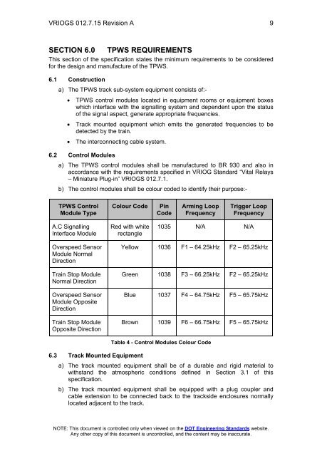
<strong>VRIOGS</strong> <strong>012.7.15</strong> Revision A 9SECTION 6.0TPWS REQUIREMENTSThis section of the specification states the minimum requirements to be consideredfor the design and manufacture of the TPWS.6.1 Constructiona) The TPWS track sub-system equipment consists of:-• TPWS control modules located in equipment rooms or equipment boxeswhich interface with the signalling system and dependent upon the statusof the signal aspect, generate appropriate frequencies.• Track mounted equipment which emits the generated frequencies to bedetected by the train.• The interconnecting cable system.6.2 Control Modulesa) The TPWS control modules shall be manufactured to BR 930 and also inaccordance with the requirements specified in VRIOG Standard “Vital Relays– Miniature Plug-in” <strong>VRIOGS</strong> 012.7.1.b) The control modules shall be colour coded to identify their purpose:-TPWS ControlModule TypeColour CodePinCodeArming LoopFrequencyTrigger LoopFrequencyA.C SignallingInterface ModuleRed with whiterectangle1035 N/A N/AOverspeed SensorModule NormalDirection<strong>Train</strong> Stop ModuleNormal DirectionOverspeed SensorModule OppositeDirection<strong>Train</strong> Stop ModuleOpposite DirectionYellow 1036 F1 – 64.25kHz F2 – 65.25kHzGreen 1038 F3 – 66.25kHz F2 – 65.25kHzBlue 1037 F4 – 64.75kHz F5 – 65.75kHzBrown 1039 F6 – 66.75kHz F5 – 65.75kHz6.3 Track Mounted EquipmentTable 4 - Control Modules Colour Codea) The track mounted equipment shall be of a durable and rigid material towithstand the atmospheric conditions defined in Section 3.1 of thisspecification.b) The track mounted equipment shall be equipped with a plug coupler andcable extension to be connected back to the trackside enclosures normallylocated adjacent to the track.NOTE: This document is controlled only when viewed on the DOT Engineering Standards website.Any other copy of this document is uncontrolled, and the content may be inaccurate.