Draft Overview of HPC Construction - EDF Hinkley Point
Draft Overview of HPC Construction - EDF Hinkley Point
Draft Overview of HPC Construction - EDF Hinkley Point

You also want an ePaper? Increase the reach of your titles
YUMPU automatically turns print PDFs into web optimized ePapers that Google loves.
<strong>Draft</strong> <strong>Overview</strong> <strong>of</strong> <strong>HPC</strong><strong>Construction</strong>February 2011This is a draft document which <strong>EDF</strong> Energy will continue to develop during the preparation <strong>of</strong>its application for development consent to the Infrastructure Planning Commission later thisyear. The contents <strong>of</strong> this document are likely to change prior to final submission <strong>of</strong> theapplication. The consultation document entitled ‘<strong>Hinkley</strong> <strong>Point</strong> C: Update on and ProposedChanges to the Preferred Proposals’ details the material changes to the proposals since Stage 2consultation, and in the event <strong>of</strong> any inconsistency between this draft document and theconsultation document, it is the consultation document that takes precedence.
[This page is intentionally left blank]2 DRAFT | <strong>Overview</strong> <strong>of</strong> <strong>HPC</strong> <strong>Construction</strong>| February 2011
CONTENTS1. INTRODUCTION .............................................................................................................52. STRATEGIC CONSTRUCTION PROGRAMME .............................................................72.1 Introduction......................................................................................................................72.2 <strong>Hinkley</strong> <strong>Point</strong> C Project <strong>Construction</strong> Programme ...........................................................83. PRELIMINARY WORKS................................................................................................113.1 Introduction....................................................................................................................113.2 Remediation and Associated Works..............................................................................113.3 Preliminary Works .........................................................................................................114. CONSTRUCTION AT HINKLEY POINT C ....................................................................154.1 Introduction....................................................................................................................154.2 <strong>Construction</strong> <strong>of</strong> the Sea Wall .........................................................................................234.3 <strong>Construction</strong> <strong>of</strong> Buildings and Infrastructure..................................................................235. CONSTRUCTION LOGISTICS......................................................................................335.1 Introduction....................................................................................................................335.2 Freight and Materials.....................................................................................................335.3 <strong>Construction</strong> Workforce .................................................................................................345.4 <strong>Construction</strong> Waste and Excavated Materials ...............................................................35TABLESTable 4.1: Proposed Areas <strong>of</strong> Land Use during the Peak Phase <strong>of</strong> <strong>Construction</strong> ......................16FIGURESFigure 2.1: Indicative <strong>Construction</strong> Programme ..........................................................................9Figure 4.1: Indicative <strong>Construction</strong> Activities 2013 ....................................................................37Figure 4.2: Indicative <strong>Construction</strong> Activities Late 2014 ............................................................38Figure 4.3: Indicative <strong>Construction</strong> Activities Mid-2018 .............................................................39Figure 4.4: Indicative <strong>Construction</strong> Activities Late 2019 ............................................................40Figure 4.5: On-site Campus ......................................................................................................25DRAFT | <strong>Overview</strong> <strong>of</strong> <strong>HPC</strong> <strong>Construction</strong> | February 2011 3
[This page is intentionally left blank]4 DRAFT | <strong>Overview</strong> <strong>of</strong> <strong>HPC</strong> <strong>Construction</strong>| February 2011
1. INTRODUCTION1.1.1 NNB Generation Company Limited (company number 06937084), part <strong>of</strong> <strong>EDF</strong>Energy, is the company that will ultimately make the Development Consent Orderapplication. For the purpose <strong>of</strong> this document, NNB Generation Company Limited isreferred to as <strong>EDF</strong> Energy.1.1.2 <strong>EDF</strong> Energy is planning to build a new nuclear power station at <strong>Hinkley</strong> <strong>Point</strong> nearBridgwater, Somerset, comprising two UK EPR reactor units with an expected output<strong>of</strong> approximately 1,630MW per unit.1.1.3 The new site, <strong>Hinkley</strong> <strong>Point</strong> C (<strong>HPC</strong>), is to the west <strong>of</strong> the existing <strong>Hinkley</strong> <strong>Point</strong>Power Station Complex. The new power station is based on replicating as much aspossible the design for the Flamanville 3 unit in Normandy, France, currently underconstruction.1.1.4 This paper describes the programme and methodology for constructing a newnuclear power station at <strong>Hinkley</strong> <strong>Point</strong> C and includes the following: Section 2 outlines the strategic construction programme for the <strong>Hinkley</strong> <strong>Point</strong> CProject including the proposed preliminary works, construction <strong>of</strong> <strong>Hinkley</strong> <strong>Point</strong> Cand the construction and operation <strong>of</strong> the associated developments. Section 3 describes any applications separate to the application for DevelopmentConsent for works on-site prior to the main construction phase, including thepreliminary works (site preparation works and the temporary jetty) to facilitate theconstruction <strong>of</strong> <strong>Hinkley</strong> <strong>Point</strong> C. Section 4 sets out the programme and key construction phases for theconstruction <strong>of</strong> <strong>Hinkley</strong> <strong>Point</strong> C. A description is provided for the key constructionactivities, including proposed land use and site facilities. Section 5 describes the construction logistics strategy for the <strong>Hinkley</strong> <strong>Point</strong> CDevelopment Site (including management <strong>of</strong> freight and materials, and theconstruction workforce).DRAFT | <strong>Overview</strong> <strong>of</strong> <strong>HPC</strong> <strong>Construction</strong> | February 2011 5
[This page is intentionally left blank]6 DRAFT | <strong>Overview</strong> <strong>of</strong> <strong>HPC</strong> <strong>Construction</strong> | February 2011
2. STRATEGIC CONSTRUCTIONPROGRAMME2.1 Introduction2.1.1 This section presents the strategic construction programme for the full <strong>Hinkley</strong> <strong>Point</strong>C Project, including the <strong>Hinkley</strong> <strong>Point</strong> C Development Site and all <strong>of</strong> the associateddevelopments.2.1.2 The overall programme for the construction at <strong>Hinkley</strong> <strong>Point</strong> C, including thepreliminary works, is anticipated to take approximately nine years and includes: the site preparation works; construction and subsequent operation <strong>of</strong> the temporary jetty; construction <strong>of</strong> <strong>Hinkley</strong> <strong>Point</strong> C, including the nuclear island, conventional island,the balance <strong>of</strong> plant, ancillary buildings and structure, the National Grid 400kVsubstation and overhead line transmission infrastructure; construction <strong>of</strong> the cooling water infrastructure; construction <strong>of</strong> the on-site accommodation campus; dismantling and removal <strong>of</strong> the temporary jetty; removal <strong>of</strong> the on-site accommodation campus; and landscape restoration.2.1.3 <strong>EDF</strong> Energy has identified a number <strong>of</strong> associated developments which areconsidered necessary to facilitate the construction, and in some instances, theoperation <strong>of</strong> <strong>Hinkley</strong> <strong>Point</strong> C and to mitigate potential environmental impactsassociated with the Project. In the absence <strong>of</strong> the proposed associateddevelopments, the likely traffic and socio-economic impacts associated with theconstruction and operation <strong>of</strong> <strong>Hinkley</strong> <strong>Point</strong> C would be significantly greater in thelocal area. The proposed associated developments include: Accommodation campuses for up to 1,510 construction workers on-site and inBridgwater. Park and ride facilities close to Junctions 23 and 24 <strong>of</strong> the M5 motorway,Cannington and Williton. Freight management facilities, courier consolidation facilities and an inductioncentre close to Junction 23 <strong>of</strong> the M5 motorway. Freight management facilities close to Junction 24 <strong>of</strong> the M5 motorway. A bypass around the west <strong>of</strong> Cannington to minimise the amount <strong>of</strong> constructiontraffic using the local road network within the village. Refurbishment <strong>of</strong> the existing Combwich Wharf facility to accommodate the arrival<strong>of</strong> approximately 180 Abnormal Indivisible Loads (AILs) and other constructionDRAFT | <strong>Overview</strong> <strong>of</strong> <strong>HPC</strong> <strong>Construction</strong> | February 2011 7
elated goods, over a period <strong>of</strong> approximately six years. A laydown area will alsobe provided adjacent to Combwich Wharf.2.2 <strong>Hinkley</strong> <strong>Point</strong> C Project <strong>Construction</strong> Programme2.2.1 As illustrated in Figure 2.1, the <strong>Hinkley</strong> <strong>Point</strong> C construction programme isanticipated to commence with the site preparation works in spring 2011, followed bythe main construction in summer 2012, through the Development Consent granted bythe IPC. The overall construction phase is anticipated to take approximately 9 years,with the first UK EPR reactor unit operational in 2018, and the second UK EPRreactor unit operational approximately 18 months later.2.2.2 Some landscape restoration to the south <strong>of</strong> the southern construction phase area willbe undertaken early in the construction phase to provide early screening from theconstruction works. The final landscape restoration works will commence once theconstruction phase is complete and <strong>Hinkley</strong> <strong>Point</strong> C is operational. Initially the sitewill be cleared, including the on-site accommodation campus, and then the <strong>Hinkley</strong><strong>Point</strong> C Development Site will be landscaped which will take up to three years tocomplete.2.2.3 In summary the construction schedule is currently estimated to be as set out below.However, the schedule is dependent on external factors, which are not within thecontrol <strong>of</strong> <strong>EDF</strong> Energy, so a timescale <strong>of</strong> activities is more reliable than precise dates: Commence site preparation works spring 2011 (subject to consent); Commence construction <strong>of</strong> the temporary jetty late 2011 (subject to consent); <strong>Construction</strong> <strong>of</strong> <strong>Hinkley</strong> <strong>Point</strong> C commences (subject to the grant <strong>of</strong> DevelopmentConsent) in summer 2012; Jetty completion and commissioning in late 2012; Completion and commencement <strong>of</strong> operation <strong>of</strong> the first UK EPR reactor unit in2018; Completion and commencement <strong>of</strong> operation <strong>of</strong> the second UK EPR reactor unit18 months following the first unit; Dismantling and removal <strong>of</strong> the temporary jetty within three years <strong>of</strong> the secondUK EPR reactor unit becoming operational; and Restoration <strong>of</strong> the <strong>Hinkley</strong> <strong>Point</strong> C Development Site within three years <strong>of</strong> thesecond UK EPR reactor unit becoming operational.2.2.4 This schedule is based on the assumption that the temporary jetty will be grantedconsent and construction will commence in late 2011. The jetty will takeapproximately one year to construct, which includes a period for delays in theconstruction programme as a result <strong>of</strong> any adverse weather conditions (‘weatherrisk’). As such, there is expected to be a period <strong>of</strong> up to six months between the start<strong>of</strong> the main construction works and completion <strong>of</strong> the jetty construction; during thisperiod materials will be transported to the site via the road network.8 DRAFT | <strong>Overview</strong> <strong>of</strong> <strong>HPC</strong> <strong>Construction</strong> | February 2011
2.2.5 The construction schedule for each <strong>of</strong> the associated developments is also providedin Figure 2.1. Further details are provided in the <strong>Draft</strong> <strong>Overview</strong> <strong>of</strong> AssociatedDevelopment <strong>Construction</strong>.Figure 2.1: Indicative <strong>Construction</strong> ProgrammeDRAFT | <strong>Overview</strong> <strong>of</strong> <strong>HPC</strong> <strong>Construction</strong> | February 2011 9
[This page is intentionally left blank]10 DRAFT | <strong>Overview</strong> <strong>of</strong> <strong>HPC</strong> <strong>Construction</strong> | February 2011
3. PRELIMINARY WORKS3.1 Introduction3.1.1 A series <strong>of</strong> activities are proposed to be completed before the main <strong>Hinkley</strong> <strong>Point</strong> Cconstruction activities can commence. Some <strong>of</strong> these works can be completed priorto the determination <strong>of</strong> the DCO application and will be done at <strong>EDF</strong> Energy’s risk toallow the main construction works to start as soon after the decision as possible.3.2 Remediation and Associated Works3.2.1 Prior to commencing the site preparation works a small number <strong>of</strong> remediation andassociated works will have been undertaken in the northern part <strong>of</strong> the site. Theseworks were submitted as a stand-alone application separate from any proposals fordevelopment that might come forward in the future for <strong>Hinkley</strong> <strong>Point</strong> C. These workswere granted by Somerset County Council in January 2011, subject to conditions.3.2.2 The north-eastern part <strong>of</strong> the site includes a construction debris mound whichoriginated from the construction <strong>of</strong> the existing <strong>Hinkley</strong> <strong>Point</strong> Power Station Complex.Site investigations identified the presence <strong>of</strong> asbestos containing materials (ACMs) inthe mound and in areas in the vicinity <strong>of</strong> the mound. The proposed works includeremoving any potential hazard to human health and the environment which may becaused by the presence <strong>of</strong> asbestos containing materials on the site. The applicationprovided for the excavation and removal <strong>of</strong> the contaminated soil and the re-use <strong>of</strong>existing uncontaminated stockpiled materials as engineered fill within the site and asbackfilling material for the decommissioning <strong>of</strong> <strong>Hinkley</strong> <strong>Point</strong> A.3.2.3 In addition to these remediation works, the application also included proposals forassociated works, including the creation <strong>of</strong> temporary areas <strong>of</strong> hardstanding formaterial segregation and stockpiling, plus temporary portacabin <strong>of</strong>fices. It alsoincluded proposals to create a temporary helipad.3.3 Preliminary Works3.3.1 To facilitate the construction <strong>of</strong> a new nuclear power station at <strong>Hinkley</strong> <strong>Point</strong> C, <strong>EDF</strong>Energy submitted two applications to undertake some preliminary works at the<strong>Hinkley</strong> <strong>Point</strong> C Development Site, comprising site preparation works and theconstruction and operation <strong>of</strong> a temporary jetty, which also provides for itsdismantling and removal once operation has ceased. These applications weresubmitted to West Somerset Council (WSC) and the Marine ManagementOrganisation (MMO) respectively.DRAFT | <strong>Overview</strong> <strong>of</strong> <strong>HPC</strong> <strong>Construction</strong> | February 2011 11
a) Site Preparation Works3.3.2 The planning application for the site preparation works provided for: Site establishment works, including the creation <strong>of</strong> construction compounds andassociated facilities, car parks, and the laying, replacement and/or diversion <strong>of</strong>services networks. Fencing and site clearance, including the demolition <strong>of</strong> existing barns within thedevelopment site; removal <strong>of</strong> existing areas <strong>of</strong> woodland and hedgerows; andvegetation clearance. Earthworks to create the platforms required for the construction <strong>of</strong> <strong>Hinkley</strong> <strong>Point</strong>C. It is estimated that approximately 2.3 million m 3 (unbulked) <strong>of</strong> material wouldbe excavated during the site preparation works and stockpiled on-site for re-use.The proposed stockpile areas and stockpiling methodologies are determined bythe volumes and properties <strong>of</strong> the materials, requiring the different types <strong>of</strong>materials to be stored in separate stockpiles and managed accordingly. It isanticipated that on average approximately 200,000m 3 (unbulked) <strong>of</strong> materialwould be excavated within the application site per month throughout the sitepreparation works, based on the sequencing <strong>of</strong> works around the site and thetransport <strong>of</strong> excavated materials. The sequence <strong>of</strong> the excavations and stockpilingis generally based on the following events: removal <strong>of</strong> topsoil to storage areas; removal <strong>of</strong> subsoil and overburden to storage areas, dependent uponindividual properties; creation <strong>of</strong> landscaped areas, using subsoil, overburden and topsoil asrequired; removal <strong>of</strong> weathered rock to storage areas or to form platforms; and removal <strong>of</strong> fresh rock as required to storage areas or to form platforms.All the material excavated during the earthworks will remain on-site as part <strong>of</strong> theplatforms, stockpiles or landscaping. Culverting <strong>of</strong> Holford Stream to allow for creation <strong>of</strong> a construction platform area.The culvert would be constructed from a point adjacent to the western boundary<strong>of</strong> the site, across to the eastern boundary <strong>of</strong> the site, where it would return waterinto the existing open Holford Stream watercourse. <strong>Construction</strong> <strong>of</strong> a surface water drainage system outfalling into the Bridgwater Bayand Holford Stream ensuring that: water is discharged at controlled rates (greenfield run-<strong>of</strong>f rates being achievedfor discharges into Holford Stream downstream <strong>of</strong> the site). all surface water discharges meet appropriate water quality standards in terms<strong>of</strong> suspended sediments and other possible contaminants (e.g. hydrocarbons); the drainage is designed using the principles <strong>of</strong> Sustainable Drainage Systems(SuDS), including water minimisation and re-use wherever possible; and the design for the drainage strategy is based on a 1 in 30 year storm eventoccurring during the construction period.12 DRAFT | <strong>Overview</strong> <strong>of</strong> <strong>HPC</strong> <strong>Construction</strong> | February 2011
Dewatering <strong>of</strong> the working areas around the areas proposed for deeperexcavations during the main construction phase. Water collected from dewateringwould be discharged to the surface water drainage system described above. <strong>Construction</strong> <strong>of</strong> a temporary retaining structure along part <strong>of</strong> the northern edge <strong>of</strong>the main platform to retain the elevated main platform above the natural gradelevel. Development <strong>of</strong> a network <strong>of</strong> haulage roads to facilitate the movement <strong>of</strong> vehiclesand soil and rock materials around the site, including: a north-south haulage road which would allow for the transfer <strong>of</strong> excavatedmaterial to the southern part <strong>of</strong> the site; a haulage road network in the northern part <strong>of</strong> the site, which would vary inlocation and level to suit the ongoing platform development to eventually tieinto the site compounds as they are developed; and a service road around the perimeter <strong>of</strong> the site within the security fence toallow security and maintenance personnel access to inspect and maintain thefence line. <strong>Construction</strong> <strong>of</strong> site access points to the north-east <strong>of</strong> the site to provide the mainsite access during the site preparation works, with a second site access gate tothe south-east <strong>of</strong> the site to provide access for Heavy Goods Vehicles (HGVs)and deliveries to the site. Two roundabouts would be constructed to the north-eastand south-east <strong>of</strong> the site to serve these access points. Installation and commissioning <strong>of</strong> two batching plants; these will not be used forconcrete production with the exception <strong>of</strong> concrete tests until the DevelopmentConsent is granted.b) Temporary Jetty3.3.3 The applications for the temporary jetty provided for the construction and operation <strong>of</strong>a temporary jetty extending <strong>of</strong>f the north-west coast <strong>of</strong> the construction site including: <strong>Construction</strong> <strong>of</strong> haulage roads, including access to and along the beach t<strong>of</strong>acilitate construction <strong>of</strong> the onshore works; Piling for the jetty bridge and head, using tubular steel piles. The piles will beinserted using either the ‘drill and drive’ technique or into pre-drilled socketswhere they would be grouted into place. The onshore and foreshore piles wouldbe inserted using land-based equipment. The <strong>of</strong>fshore piling would use a jack-upbarge; <strong>Construction</strong> <strong>of</strong> the jetty bridge, incorporating a roadway and conveyors foraggregate and cement; <strong>Construction</strong> <strong>of</strong> the jetty head, incorporating ship mooring provisions, aggregateand cement receipt equipment and facilities for jetty workers;DRAFT | <strong>Overview</strong> <strong>of</strong> <strong>HPC</strong> <strong>Construction</strong> | February 2011 13
Dredging <strong>of</strong> a berthing pocket alongside the jetty head to allow ships <strong>of</strong> up to5,000 dead weight tonnes to berth; <strong>Construction</strong> <strong>of</strong> onshore storage stockpiles for aggregate and silos for cement;and Compulsory acquisition <strong>of</strong> certain land interests required for these works.3.3.4 Materials and construction equipment deliveries will be predominantly by sea for the<strong>of</strong>fshore works and by road for the onshore and foreshore works.14 DRAFT | <strong>Overview</strong> <strong>of</strong> <strong>HPC</strong> <strong>Construction</strong> | February 2011
4. CONSTRUCTION AT HINKLEY POINT C4.1 Introduction4.1.1 This section provides a description <strong>of</strong> key site preparation and construction activitiesand land uses.a) Land Use4.1.2 This section describes at a high level the main land usage throughout theconstruction activity.4.1.3 The temporary construction areas extend to the west and south <strong>of</strong> the permanentpower station site. The overall construction site area is bisected by a track (GreenLane) running east-west, which has archaeological and ecological significance. Thistrack will be retained and protected for most <strong>of</strong> its length and two crossing points areprovided for construction traffic. The southern limit for main construction activity hasbeen set as OS grid line 144750mN, to provide a buffer zone between the mainconstruction activity and the village <strong>of</strong> Shurton. However, limited works (landscapingand the construction <strong>of</strong> an emergency access road) will take place within this bufferzone.4.1.4 A number <strong>of</strong> badger setts are relocated to the west <strong>of</strong> the construction site. Thesebadger setts, together with a bat house, earth bunds and water management zone(s)will be integrated into a landscaped western boundary, which serves to reduce thevisibility <strong>of</strong> the works from the west.4.1.5 A temporary jetty will be located in the north-west <strong>of</strong> the site to facilitate the import <strong>of</strong>bulk materials, primarily aggregate, sand and cement for concrete production andother construction materials.4.1.6 An on-site accommodation campus will be located in the south-east corner <strong>of</strong> the<strong>Hinkley</strong> <strong>Point</strong> C Development Site.4.1.7 Access to the construction site for material deliveries will be via a roundabout into thesouthern part <strong>of</strong> the site. This southern access incorporates a waiting area andsearch lanes for delivery vehicles. Workers will mostly be bussed to site and arrivevia the northern roundabout and a coach drop-<strong>of</strong>f and parking area on the site <strong>of</strong> thesouthern permanent station car park. Workers will enter the site via turnstiles and asearch hall for security control.4.1.8 During the site preparation works, the construction areas will be levelled into a series<strong>of</strong> platforms and excavation <strong>of</strong> the main site will start. The excavation and groundterracing will involve approximately four million m 3 <strong>of</strong> material. To avoid additionalroad journeys, all the material will be retained on site. This will necessitate theculverting <strong>of</strong> Holford Stream to provide space for stockpiles and working platforms.In the south-west corner <strong>of</strong> the site will be storage areas for topsoil, re-usableexcavated rock, weathered rock and overburden. The re-usable rock will be used forengineering fill, and the other material will be stored for use in the final sitelandscaping. Part <strong>of</strong> the weathered rock and overburden stockpile will be prepared asa platform for contractors’ workshops and storage areas.DRAFT | <strong>Overview</strong> <strong>of</strong> <strong>HPC</strong> <strong>Construction</strong> | February 2011 15
4.1.9 Water management zones will be located in the north, east and west <strong>of</strong> the site tocontrol the discharge <strong>of</strong> water from run-<strong>of</strong>f and dewatering activities into the sea andlocal watercourses. An additional water management zone may be required to thesouth <strong>of</strong> the southern construction area, to deal with run-<strong>of</strong>f from the proposed earlylandscaped area. The northern water management zones will be removed as thepermanent site drainage systems are implemented.4.1.10 Areas <strong>of</strong> the site that are not required for permanent plant and buildings will be usedas temporary contractors’ areas. Allocations will change over time and thecontractors will be required to install whatever facilities they need for their workersand construction equipment and materials. Service connections for the contractors’use (electricity, water, drainage) will be made available in close proximity <strong>of</strong> thecontractors’ areas.4.1.11 Although the construction site plans show some temporary buildings, the actualprovisions and locations will be developed in conjunction with the relevantcontractors. In addition, muster points, welfare and medical facilities will be provided.The locations <strong>of</strong> these facilities will need to be validated with the early contractorsand many will be relocated as the work progresses.4.1.12 The construction <strong>of</strong> the National Grid 400kV substation in the south-east corner <strong>of</strong>the permanent power station area, along with the diversion <strong>of</strong> existing overhead linesto facilitate connections to the National Grid transmission system will be undertakenby National Grid as a separate activity. A temporary working area will be provided tothe south and east <strong>of</strong> the substation for the duration <strong>of</strong> National Grid’s constructionworks.4.1.13 <strong>Construction</strong> <strong>of</strong> the <strong>EDF</strong> Energy overhead transmission lines and towers on thepermanent power station site will be undertaken by <strong>EDF</strong> Energy’s contractors.4.1.14 The working areas for some <strong>of</strong> the contractors, such as the marine works andsubstation, will be located wholly or partly within the footprint <strong>of</strong> the permanentdevelopment site. The layout <strong>of</strong> the site will vary over the construction period but,taking this into account, the anticipated principal uses <strong>of</strong> the overall land area withinthe development site at the peak phase <strong>of</strong> construction, in 2016, are presented inTable 4.1 below.Table 4.1: Proposed Areas <strong>of</strong> Land Use during the Peak Phase <strong>of</strong> <strong>Construction</strong>Land UseFinal permanent power station area 66.6<strong>Construction</strong> site entrance and access roads 22.6Landscape and nature buffers/reserves 25.9Overburden and topsoil storage 9.8Workshops and storage 11.9On-site accommodation campus 4.0Main civil works contractor 8.8Stockpile <strong>of</strong> material for re-use 13.3Area (ha)Low-lying land unsuitable for construction use 2.516 DRAFT | <strong>Overview</strong> <strong>of</strong> <strong>HPC</strong> <strong>Construction</strong> | February 2011
Land UseArea (ha)Nuclear steam supply system contractor 2.1Mechanical and electrical erection contractor 2.1Main turbine contractor 1.9Heavy fabrication workshop 1.1Roads and networks contractor 0.9Total 173.54.1.15 The land uses will change throughout the construction phase, reflecting the differentstages <strong>of</strong> development activity. For example, the area allocated to the civil workscontractor will be reduced and the spare land reallocated to the main mechanical andelectrical contractors as the balance <strong>of</strong> work on the site changes.b) <strong>Construction</strong> Schedule and Phasing4.1.16 This section sets out the construction programme and the key phases within it.Figures 4.1 - 4.4, at the back <strong>of</strong> this document, are indicative phasing plans for thefull construction phase from site preparation through to completion <strong>of</strong> <strong>Hinkley</strong> <strong>Point</strong> Cand land restoration. The series <strong>of</strong> plans identifies the construction activities at keyphases in the construction programme, however it should be noted that these aresubject to refinement and schedule changes. It should also be noted that within themain construction site areas there will be activities and uses that will remainundefined, including minor temporary facilities and structures.4.1.17 At the time <strong>of</strong> Development Consent being granted, anticipated to be in 2012, anumber <strong>of</strong> construction activities are expected to have been completed or beunderway as follows: The temporary jetty is under construction, utilising a temporary beach accessroad. Holford Stream has been culverted, the access roundabouts and initial haulageroads have been built and the material stockpiles are in use. The southern part <strong>of</strong> the western site boundary has been landscaped and planted. A temporary earth retaining structure has been built at the low-lying section <strong>of</strong> thecoastline to enable a level platform to be established behind. A permanent station car park has been constructed and others are underconstruction. The main platform areas have been established and excavation <strong>of</strong> the areas forthe main plant buildings has started. Contractors’ working areas have been established. The base for the reactor building liner fabrication building has been prepared. Water management zones have been established for the management <strong>of</strong>drainage.DRAFT | <strong>Overview</strong> <strong>of</strong> <strong>HPC</strong> <strong>Construction</strong> | February 2011 17
4.1.18 As described in Section 3, the site preparation works are currently the subject <strong>of</strong> aconsent application being determined by WSC and the temporary jetty by consentapplications being determined by the MMO and the Secretary <strong>of</strong> State.4.1.19 Figure 4.1 shows the indicative layout <strong>of</strong> the construction site at the time <strong>of</strong> firstsafety-related concrete, anticipated to be in 2013, where: The temporary jetty has been completed and is in use. The sea wall in front <strong>of</strong> the permanent power station site has been constructed. The permanent station car parks have been built. The southern car park is in usefor park and ride buses for the workers and part <strong>of</strong> the south-eastern car park hasbeen allocated to the National Grid 400kV substation contractor as a workingarea. All the principal contractors’ working areas have been established. The construction <strong>of</strong> the National Grid 400kV substation has commenced. Security access controls have been established for materials deliveries andworkers. Site <strong>of</strong>fices have been built near to the southern access. The on-siteaccommodation campus area has been levelled and accommodation blocks andfacilities are in the final stages <strong>of</strong> construction. The Public Information Centre and some permanent <strong>of</strong>fices are underconstruction. Many <strong>of</strong> the tower cranes have been erected on the main power station area. Excavations for unit 1 have been completed and the foundations prepared forpouring the first safety-related concrete. The liner fabrication building is complete and in use. <strong>Construction</strong> <strong>of</strong> the marine works has started, including boring the tunnels for thecooling water. Landscaping <strong>of</strong> the area to the south <strong>of</strong> the main construction area is in progress,as is the construction <strong>of</strong> the emergency access road together with its bridge overBum Brook.4.1.20 Figure 4.2 shows the indicative layout <strong>of</strong> the construction site at the start <strong>of</strong> themechanical and electrical works, anticipated to be in late 2014, where: The excavations for unit 2 are complete and ready for the safety-related concrete. The <strong>of</strong>fshore cooling water works are virtually complete, including tunnels, accessshafts and intake structures, with the discharge structures remaining to beinstalled. The buildings for unit 1 and most <strong>of</strong> the shared (unit 1 and 2) buildings are underconstruction and the excavations are being back-filled. A number <strong>of</strong> temporary buildings are complete or under construction in thecontractors’ working areas.18 DRAFT | <strong>Overview</strong> <strong>of</strong> <strong>HPC</strong> <strong>Construction</strong> | February 2011
The installation <strong>of</strong> mechanical and electrical equipment is under way. The Public Information Centre, permanent site <strong>of</strong>fices and the outage accesscontrol building are complete. Temporary access to the Public Information Centreis established via the south-eastern permanent station car park. The on-site accommodation campus is complete. The National Grid 400kV substation is under construction.4.1.21 Figure 4.3 shows the indicative layout <strong>of</strong> the construction site at the time when unit 1commences operation, anticipated to be mid-2018, where: Unit 1 is complete and is fenced <strong>of</strong>f from the rest <strong>of</strong> the construction site. The ancillary buildings for both units are complete. The National Grid 400kV substation is complete and National Grid’s lines havebeen diverted to connect the substation. Unit 2 buildings are substantially complete and mechanical and electricalequipment installation is nearing completion. The interim storage buildings for intermediate level waste and spent fuel areunder construction.4.1.22 Figure 4.4 shows the indicative layout <strong>of</strong> the construction site at the time when unit 2commences operation where: Both units <strong>of</strong> the power station are complete and fenced <strong>of</strong>f from the rest <strong>of</strong> theconstruction site. <strong>Construction</strong> <strong>of</strong> the interim storage buildings is complete. Many <strong>of</strong> the contractors’ temporary facilities are being dismantled and removed.4.1.23 After the start-up <strong>of</strong> unit 2, the following activities will be undertaken: The temporary jetty will be dismantled and removed. The on-site accommodation campus will be closed, the buildings dismantled andremoved and the area cleared. The contractors’ areas will be cleared and temporary services removed. Temporary re-routing <strong>of</strong> the emergency access road will be established to allowthe final landscaping to be undertaken in the southern construction area. The remaining buildings will be completed. Final landscaping and planting will be undertaken, incorporating the finalalignment <strong>of</strong> the emergency access road and the access road to the PublicInformation Centre.DRAFT | <strong>Overview</strong> <strong>of</strong> <strong>HPC</strong> <strong>Construction</strong> | February 2011 19
c) Contractor Mobilisation4.1.24 Following the granting <strong>of</strong> Development Consent, the main civil works will completemobilisation and the marine works and sea wall contractors will mobilise. This will befollowed progressively by the mobilisation <strong>of</strong> the other site contractors. Mobilisationwill include: Induction training for site workers, including security and immigration checks,training in safety awareness and site arrangements, and signing up to theworkers’ code <strong>of</strong> conduct prior to the issue <strong>of</strong> a site pass. Preparation and approval <strong>of</strong> method statements for the work to be undertakencovering safety, environmental, quality and regulatory aspects. Installation <strong>of</strong> the contractors’ site compound facilities. Installation and testing <strong>of</strong> key temporary plant, such as tower cranes.d) <strong>Construction</strong> <strong>of</strong> Contractor Compound Areas4.1.25 The contractors’ compound areas will be prepared as level platforms by the sitepreparation works contractor. Surface water drainage will be via the constructiondrainage systems installed during the site preparation works. Service connections forwater, electricity, sewage and telecommunications will be provided in close proximityto each compound.4.1.26 Each contractor will provide fencing and lighting (in accordance with the lightingstrategy to be submitted with <strong>EDF</strong> Energy’s application for Development Consent) fortheir own compound. They will install facilities for <strong>of</strong>fice and welfare use for theirworkforce, together with workshops and storage facilities as necessary, connectingthese to the adjacent services connection points.e) Site Access4.1.27 The <strong>Hinkley</strong> <strong>Point</strong> C Development Site will be arranged as a secure construction sitewith controls on the people and materials entering and leaving the site. Newroundabouts will be constructed at the southern and northern site access points.4.1.28 Most <strong>of</strong> the materials required for the production <strong>of</strong> concrete (sand, aggregate,cement and cement substitutes) will be transported to site by sea and will be<strong>of</strong>floaded at the temporary jetty. The jetty could also be used for the import <strong>of</strong> otherbulk materials to the site, where practicable.4.1.29 Other construction materials will be delivered by road and will enter the site via thesouthern roundabout. As detailed in the <strong>Draft</strong> Freight Management Strategy, allroad deliveries will be managed using a computerised delivery management systemwhich controls the timing <strong>of</strong> deliveries. Vehicles arriving via the motorway networkswill be required to check-in at one <strong>of</strong> the freight management facilities at J23 or J24and will be despatched to site in accordance with a strict timetable. Delivery vehicleswill be subject to search in line with the security policy before entry and when leavingthe site. Deliveries will normally be made to the respective site contractor’scompound and the delivery vehicle will then leave the site.20 DRAFT | <strong>Overview</strong> <strong>of</strong> <strong>HPC</strong> <strong>Construction</strong> | February 2011
4.1.30 Abnormal Indivisible Loads (AILs) which are subject to road transport restrictions,including major equipment items such as the reactor pressure vessel, will bedelivered by sea to Combwich Wharf and will then be transported to site by road.These deliveries will bypass the southern site entrance and will be transporteddirectly to the point <strong>of</strong> installation via the northern roundabout. All such deliveries willbe subject to special controls to minimise the impact on other road users.4.1.31 Waste and other materials despatched from site will also be subject to controls.Where practicable, sea transport will be used, but most transport will be by road. Thedelivery management system will be used to manage the timing <strong>of</strong> freight vehicles,including empty vehicles, leaving the site to ensure compliance with the transportplan for waste and materials movements.4.1.32 In accordance with the travel plan, nearly all personnel working at the constructionsite will travel to and from site by bus. Buses will collect workers from <strong>of</strong>f-sitecampuses, park and ride sites and other identified locations and take them via thenorthern roundabout to the site personnel entrance adjacent to the south permanentstation car park. This car park will be dedicated to buses for the duration <strong>of</strong> theconstruction period, although the access route will vary according to the stage <strong>of</strong>construction works. Workers will enter the site through turnstiles adjacent to the busdrop-<strong>of</strong>f point and will be subject to security controls and searches in line with thesecurity policy. Buses to take workers home will wait within the designated car parkand will leave as soon as they are full.4.1.33 Very limited car parking will be available during the construction period. This will beprovided outside the construction site fence and no private cars will be allowed withinthe construction site. Each contractor will be allocated a small number <strong>of</strong> parkingspaces sufficient to enable them to fulfil their responsibilities for health and safetyand worker welfare. In addition, there will be a small number <strong>of</strong> parking spacesallocated for visitors, including VIP visitors to the site. Provision for pedal cyclists willbe made at the construction site, but motorcyclists will be required to use the parkand ride sites.4.1.34 Workers resident in the on-site accommodation campus will be able to enter the sitevia dedicated turnstiles adjacent to the campus. All other persons who do not walk orcycle to site and are not entitled to the use <strong>of</strong> one <strong>of</strong> the limited car park spaces willbe required to use the bus service to the site, via the park and ride sites if necessary.f) Internal Haulage Roads4.1.35 During the site preparation works, a number <strong>of</strong> haulage roads would be developed onsite to facilitate the movement <strong>of</strong> vehicles carrying excavation and constructionmaterials around the site. These haulage roads are indicated on Figures 4.1 - 4.4and will vary in location and level according to the construction needs. Wherepracticable, the haulage roads are aligned with the routes for the permanent roads.4.1.36 In addition, a temporary service road will be constructed around the perimeter <strong>of</strong> thesite within the security fence, to allow security and maintenance personnel access toinspect and maintain the fence line.4.1.37 The haulage roads would be constructed in accordance with the current relevantBritish Standards and the Highways Agency Design Manual as required for heavyDRAFT | <strong>Overview</strong> <strong>of</strong> <strong>HPC</strong> <strong>Construction</strong> | February 2011 21
vehicle usage and estimated traffic volumes. These haulage roads would be surfacedwith tarmac or compacted granular material as appropriate, and the surface waterdrainage would be tied into the construction drainage systems to be installed duringthe site preparation works.4.1.38 Lighting will be provided along the haulage roads in line with the lighting strategy. tobe submitted with the application for Development Consent. This will ensuresufficient lighting levels for safety whilst minimising stray light and adverse visualimpact from <strong>of</strong>f-site viewpoints.g) Civils Worksi. Introduction4.1.39 The civil works will pick up from the site preparation works, completing the deepexcavations before starting the building construction.ii. Platform Development and Deep Excavation4.1.40 Most <strong>of</strong> the platform development and ground terracing will have been undertakenduring the site preparation works. However, as the deep excavations areundertaken, additional platforms and access routes will be required to facilitateaccess. The deep excavations will involve mainly fresh rock, although someweathered rock will be encountered. Where practicable, mechanical excavation willbe used. However, blasting may be required and this will be strictly controlled, withappropriate warning given to nearby residents. The excavated material will betransported to the designated stockpiles in the south <strong>of</strong> the site.4.1.41 Excavations for unit 2 and the interim spent fuel store will continue after theexcavations for unit 1 are complete and construction <strong>of</strong> the unit 1 buildings areunderway.4.1.42 Backfilling <strong>of</strong> the excavations as the buildings are constructed will be managed inaccordance with strict <strong>EDF</strong> Energy requirements. Different material standards areapplied depending on the location and performance required <strong>of</strong> the backfill. Wherepracticable, excavated material will be used for backfill and this will require carefulquality control in the segregation <strong>of</strong> materials going to the stockpiles. To achieve theparticle size standards required for backfill, rock crushing plant will be used. Whereexcavated material is insufficient or unsuitable for backfill, appropriate granular fillmaterial will be imported.iii. Surface Water and Groundwater Drainage4.1.43 The construction drainage system, which will be installed during the preliminaryworks, will handle the surface run-<strong>of</strong>f and groundwater flows associated with thevarious platforms. This system will be extended to enable drainage <strong>of</strong> the deepexcavations using dewatering wells. The nature <strong>of</strong> the underlying geology indicatesthat the additional groundwater flows will be limited and predictable. However,monitoring will be carried out to measure the water quantities and quality such thatappropriate controls can be implemented as necessary.4.1.44 As part <strong>of</strong> the civil works, permanent site drainage systems will be installed. In someareas, the permanent systems will utilise parts <strong>of</strong> the construction drainage22 DRAFT | <strong>Overview</strong> <strong>of</strong> <strong>HPC</strong> <strong>Construction</strong> | February 2011
infrastructure. In these cases, the connections will be arranged to ensure that thedrainage is managed throughout the transition from temporary to permanentsystems. Parts <strong>of</strong> the temporary drainage systems within the permanent powerstation site will be in use until relatively late in the construction works and these willremain in place and will be isolated where they do not form part <strong>of</strong> the permanentinfrastructure.4.1.45 <strong>Construction</strong> drainage systems located outside the permanent power station footprintwill be removed as part <strong>of</strong> the construction area clearance and landscaping.However, the Holford Stream culvert will remain and will be integrated into theproposed landscaping scheme.4.2 <strong>Construction</strong> <strong>of</strong> the Sea Wall4.2.1 The sea wall will be constructed to provide erosion protection for the <strong>Hinkley</strong> <strong>Point</strong> Cpower station platform. It is located approximately along the line <strong>of</strong> the existing cliffsin front <strong>of</strong> the permanent power station site and will incorporate return sections ateach end <strong>of</strong> the wall to prevent erosion from the side.4.2.2 The existing cliff line will be trimmed as necessary to provide space for the wallconstruction. Rock armour will be delivered by sea and temporarily placed seaward<strong>of</strong> the works to provide protection during construction. A haulage road will be builtparallel to the cliff to provide access and the foundations <strong>of</strong> the wall will beexcavated.4.2.3 Following concreting <strong>of</strong> the wall, the area behind the wall will be backfilled with freedrainingmaterial and the rock armour will be moved to its final location at the toe <strong>of</strong>the sea wall to provide scour protection.4.2.4 The return sections at each end <strong>of</strong> the wall will be constructed <strong>of</strong> interlocking cast-insituconcrete piles, extending down into the underlying rock.4.2.5 The West Somerset Coast Path will be closed at the start <strong>of</strong> construction <strong>of</strong> the seawall and a new path will be constructed immediately behind the completed wall,connecting to the existing coastal path. An access ramp down to the beach will beprovided at the western end <strong>of</strong> the wall for inspection and maintenance. Accesssteps will be provided at three positions along the length <strong>of</strong> the wall to allow safeaccess and egress from the beach level.4.3 <strong>Construction</strong> <strong>of</strong> Buildings and Infrastructurea) Nuclear Island4.3.1 The nuclear island buildings are constructed <strong>of</strong> reinforced concrete. The concretewill be mixed on site using a batching plant and will use sand, aggregate and cementimported via the temporary jetty. In some cases, cement substitutes, such aspulverised fuel ash will be used to secure specific concrete properties. Thereinforcement will be with steel reinforcing bars, fabricated into cages appropriate tothe building geometry and strength requirements. Some reinforcement will beprefabricated into assemblies which can be lifted into place. Such pre-fabrication willnormally take place close to the workface to minimise handling issues. Where plantor equipment has subsequently to be attached to the concrete structure, embeddedDRAFT | <strong>Overview</strong> <strong>of</strong> <strong>HPC</strong> <strong>Construction</strong> | February 2011 23
attachment plates are provided and fixed to the reinforcement cage in such a waythat they are able to transmit the loads <strong>of</strong> the attached equipment into the concrete.4.3.2 Temporary formwork either <strong>of</strong> steel and/or wood will be used to create a mouldaround the reinforcement, into which the concrete is pumped. A small number <strong>of</strong> keyconcrete pours will need to be completed as a continuous activity spanning severalshifts. Local residents will be given prior warning <strong>of</strong> these activities which will involve24-hour working.4.3.3 The reactor building incorporates a steel liner which forms the inner shell <strong>of</strong> thebuilding. Sections <strong>of</strong> the liner will be pre-fabricated on-site inside a purpose-builttemporary building and then transported to the reactor building where they will becraned into position before being welded to the other liner sections.4.3.4 The reactor building is pre-stressed using steel tendons to improve its strength.During construction, tendon ducts are incorporated within the concrete walls <strong>of</strong> thebuilding and the tendons are then threaded through the ducts and tensioned in acontrolled manner before being anchored. The tendon ducts are then filled with grout.4.3.5 As the buildings are constructed, the surrounding excavations are backfilled until alevel is reached just below the final ground level. The final surfacing will beundertaken at the end <strong>of</strong> construction as part <strong>of</strong> the on-site landscaping.b) Conventional Island4.3.6 The conventional island contains a combination <strong>of</strong> reinforced concrete and steelframedbuildings. The concrete buildings will be constructed using similar methodsto the nuclear island buildings. The steel-framed buildings will be erected using prefabricatedsteel sections lifted into place using mobile cranes. Secondary steelsections will be attached to the main frame to allow cladding to be attached to makethe building weather-tight. Most <strong>of</strong> the steel sections will be fabricated <strong>of</strong>f-site andbolted or welded together in-situ, although some pre-fabrication may be carried outon-site.c) Intake and Outfall Structures4.3.7 The cooling water system draws water from the Bridgwater Bay and passes itthrough the turbine condensers and plant coolers before returning it to BridgwaterBay. The water intake structures are positioned approximately 3.3 km <strong>of</strong>fshore andthe outfall approximately 2 km <strong>of</strong>fshore. The intake and outfall are connected to thepower station cooling water pumphouse by tunnels which are lined with concrete andthe connections from the cooling water pumphouse to the turbine condensers are bymeans <strong>of</strong> buried composite steel/concrete pipes.4.3.8 The cooling water tunnels will be bored from deep onshore excavations using tunnelboring machines. The tunnels will be lined with pre-cast concrete sections as theyare bored. The excavated material will be transported back to the tunnel entrancewhere the bentonite used in the tunnel boring process is recovered for re-use beforethe rock is transported to the appropriate stockpile for use in the final landscaping.Connections to the intake and outfall structures are made via lined vertical shaftswhich are bored from the seabed down to the tunnels.24 DRAFT | <strong>Overview</strong> <strong>of</strong> <strong>HPC</strong> <strong>Construction</strong> | February 2011
4.3.9 The intake and outfall structures will be prefabricated <strong>of</strong>fsite and floated into positionover the connecting shafts before being lowered into position. The fish recovery andreturn system associated with the cooling water infrastructure and is likely to lie withinthe area identified on the phasing plans as the ‘Area for Fish Recovery and ReturnSystems and Associated Infrastructure’ (see Figures 4.1 - 4.4). The return pipe <strong>of</strong>the fish recovery and return system would be tunnelled under the foreshore.d) Ancillary Buildings4.3.10 The proposed ancillary buildings will be predominantly steel-framed although somereinforced concrete is used. <strong>Construction</strong> activities for the ancillary buildings willgenerally be similar to the conventional island buildings.e) <strong>Construction</strong> <strong>of</strong> the On-site Accommodation Campus4.3.11 The proposed on-site accommodation campus, as illustrated in Figure 4.5, wouldcomprise: accommodation blocks; amenity buildings; access roads, car parking, cycle facilities and footpaths; external sports pitches (accessible to the public) and associated welfare facilities; security <strong>of</strong>fice; access to the main construction site by turnstiles; and drainage, landscaping and ecological features.Figure 4.5: On-site CampusDRAFT | <strong>Overview</strong> <strong>of</strong> <strong>HPC</strong> <strong>Construction</strong> | February 2011 25
4.3.12 <strong>Construction</strong> <strong>of</strong> the on-site accommodation campus, which comprises preparatoryworks, is proposed to commence once the Development Consent has been granted,anticipated to be in summer 2012. It is expected that these works would takeapproximately 21 months.i. Preparatory Works4.3.13 Prior to the construction works a number <strong>of</strong> preparatory activities would beundertaken, including: site clearance, including vegetation removal; the installation <strong>of</strong> fencing around the area for the on-site accommodation campus;and construction <strong>of</strong> a landscaped earth bund to the south <strong>of</strong> the on-siteaccommodation campus.4.3.14 <strong>Construction</strong> access is proposed via a temporary section <strong>of</strong> road connected to thesouthern roundabout on the C182; this access would be retained throughout theduration <strong>of</strong> the main <strong>Hinkley</strong> <strong>Point</strong> C construction works when the on-siteaccommodation campus is operational.4.3.15 Temporary site <strong>of</strong>fices, welfare accommodation, storage and site parking areaswould be provided within the site.ii. <strong>Construction</strong> Works4.3.16 The construction works would commence with the preparation <strong>of</strong> the platform andrequired excavations for the on-site accommodation campus and associatedfacilities. Concrete works would then by undertaken to build the foundations.4.3.17 In parallel, the construction <strong>of</strong> the internal roads and parking areas would beundertaken. Initially these areas will be constructed up to base course and sub-baselevel respectively. The final layers for the roads and parking areas will be completedas one <strong>of</strong> the last works before occupation.4.3.18 The section <strong>of</strong> internal road providing access to the site would be completed undersupervision <strong>of</strong> the highway authority. The permanent entrance into the site, <strong>of</strong>f theC182, would be constructed.4.3.19 The surface water drainage, as well as foul and surface water connections, would beinstalled at the same time as the roads, parking areas and building foundations.4.3.20 It is envisaged that the buildings on-site could be partially or wholly <strong>of</strong> prefabricatedand/or modular construction on concrete foundations. The building elements, if amodular construction is used, would be delivered to the site on flat-bed vehicles, thenlifted into position by mobile cranes and connected together. The assembled shellswould be fitted-out and the internal mechanical and electrical services installed. Theutility connections will then be made.26 DRAFT | <strong>Overview</strong> <strong>of</strong> <strong>HPC</strong> <strong>Construction</strong> | February 2011
4.3.21 Two all weather five a side sports pitches would be constructed to the north <strong>of</strong> thebuildings and the internal landscaping would be implemented.4.3.22 Security fencing, with associated lighting and CCTV, would then be erected aroundthe perimeter <strong>of</strong> the site.f) <strong>Construction</strong> <strong>of</strong> the National Grid 400kV Substation4.3.23 <strong>Construction</strong> <strong>of</strong> the 400kV substation will be a separate activity, undertaken byNational Grid and its contractors. In addition to the substation, National Grid willdivert some <strong>of</strong> the existing overhead lines in the vicinity <strong>of</strong> the site to serve the newsubstation. They will also provide a new overhead line link to the existing <strong>Hinkley</strong><strong>Point</strong> B 400kV substation.4.3.24 The 400kV substation compound includes a building which will house the gasinsulated switchgear, an amenity building, workshop buildings and a diesel generatorbuilding. In addition, there will be three inductors, which will be brought by sea toCombwich Wharf and then by road to site.g) <strong>Construction</strong> <strong>of</strong> the Emergency Access Road and the Bridge Over BumBrook4.3.25 The emergency access road provides an access route to the site for emergencyvehicles, which is independent <strong>of</strong> the main site access. It runs from a junction withthe road running through Shurton to the power station outage access, via the roadconnecting Wick Moor Drive to the southern power station car park.4.3.26 The emergency access road will not normally be used and there will be a locked gateat the junction in Shurton. The road is single-track with passing places andincorporates a bridge over Bum Brook. The bridge is single lane and is designed tokeep the road above the maximum flood level <strong>of</strong> Bum Brook whilst minimising therestriction to floodwater flows. It will also incorporate a footway to provide pedestrianaccess to the landscaped areas at the south <strong>of</strong> the site.4.3.27 The emergency access road junction in Shurton will be designed in accordance withhighway standards and will incorporate provision for adequate visibility splays andturning circles for emergency service vehicles. This will necessitate the removal <strong>of</strong> alength <strong>of</strong> existing hedge in order to achieve acceptable sight lines. New hedges willbe planted as part <strong>of</strong> the landscaping scheme and a pedestrian gate will be providedalongside the locked vehicle gate to facilitate pedestrian access.4.3.28 The southern part <strong>of</strong> the emergency access road, including the junction in Shurtonand the bridge over Bum Brook, will be constructed shortly after DevelopmentConsent is granted as part <strong>of</strong> the early landscaping <strong>of</strong> the area south <strong>of</strong> grid line144750mN. The northern part <strong>of</strong> the road will initially be temporary and connect tothe construction road network, although it will only be used as an alternative accessfor emergency vehicles. Once construction <strong>of</strong> <strong>Hinkley</strong> <strong>Point</strong> C is complete and theaccommodation campus buildings have been removed, a revised temporary routewill be established through the site <strong>of</strong> the campus so that the final landscaping canbe implemented and the final road alignment can be established across thelandscaped area.DRAFT | <strong>Overview</strong> <strong>of</strong> <strong>HPC</strong> <strong>Construction</strong> | February 2011 27
h) Landscaping <strong>of</strong> the Southern <strong>Construction</strong> Phase Area4.3.29 The land south <strong>of</strong> grid line 144750mN will not be used as part <strong>of</strong> the mainconstruction site, although it will accommodate the emergency access road and itsbridge over Bum Brook. The final landscaping proposals for this area involve raisingthe ground levels in the northern part <strong>of</strong> the area and new planting.4.3.30 Planting along the southern part <strong>of</strong> this area would provide screening <strong>of</strong> the mainconstruction works.4.3.31 In order to bring forward the final planting and increase the height <strong>of</strong> the screening <strong>of</strong>the construction works from the south, it is proposed to undertake the re-modelling <strong>of</strong>most <strong>of</strong> the area south <strong>of</strong> grid line 144750mN immediately following DevelopmentConsent. <strong>Construction</strong> <strong>of</strong> the southern part <strong>of</strong> the emergency access road and thebridge over Bum Brook would take place at the same time. Final landscaping andplanting <strong>of</strong> this area would have time to develop and mature during the constructionworks.i) Utilities Infrastructure4.3.32 During the site preparation works phase, new networks <strong>of</strong> utilities will be installedwhich will provide for the main construction works and there will be a subsequenttransition to the utilities for the operating power station.i. Electrical Infrastructure4.3.33 Electrical power will be provided for the construction works by means <strong>of</strong> a dedicated(low carbon) supply from the existing <strong>Hinkley</strong> <strong>Point</strong> Power Station Complex with anew temporary distribution network serving the whole <strong>of</strong> the construction site. Oncethe new National Grid 400kV substation is complete and connected to the nationalgrid high voltage electricity transmission system, supplies for the energisation <strong>of</strong> thepermanent power station plant will be made available, prior to the main electricitygenerator connections being made. The temporary electrical systems will bedecommissioned as the construction area is cleared and the supply from the existingpower stations will be terminated.4.3.34 As part <strong>of</strong> the construction and connection <strong>of</strong> the new <strong>Hinkley</strong> <strong>Point</strong> C substation, two<strong>of</strong> the National Grid double circuit overhead National Grid lines which currently servethe existing <strong>Hinkley</strong> <strong>Point</strong> A and B stations will be diverted to connect to the new<strong>Hinkley</strong> <strong>Point</strong> C substation. A new double circuit overhead line will also be built toconnect to the existing <strong>Hinkley</strong> <strong>Point</strong> B 400kV substation.ii. Lighting4.3.35 Lighting <strong>of</strong> the access and haulage roads on the construction site will be provided by<strong>EDF</strong> Energy. The lighting design will comply with the lighting strategy and use lightfittings chosen to limit stray light and avoid impacting sensitive species such as bats.The lighting will also be designed to minimise the visibility from sensitive receptors<strong>of</strong>f-site.4.3.36 Lighting <strong>of</strong> the contractors’ compounds will be the responsibility <strong>of</strong> the individualcontractors, but <strong>EDF</strong> Energy will require such lighting to comply with the lightingstrategy and achieve the objectives indicated above.28 DRAFT | <strong>Overview</strong> <strong>of</strong> <strong>HPC</strong> <strong>Construction</strong> | February 2011
iii. Water Supplies4.3.37 A new water supply main is planned to serve the <strong>Hinkley</strong> <strong>Point</strong> C site and this will beinstalled by the local water company. This supply will serve both the constructionworks and the permanent power station via temporary and permanent distributionnetworks with metering to monitor usage. The temporary network will bedecommissioned as the construction site is cleared at the end <strong>of</strong> the constructionworks.iv. Drainage Systems4.3.38 A temporary construction drainage system will be constructed as part <strong>of</strong> the sitepreparation works. This drainage system will handle surface water run-<strong>of</strong>f from theconstruction areas and direct it via water management zones to the appropriatedischarge point. The systems will be divided into three areas corresponding to thecurrent drainage zones. The northern area drainage will be directed to theBridgwater Bay, as at present, with a discharge point located to ensure the potentialimpact on the intertidal environment is minimised. The southern construction areawill be drained to Holford Stream, as at present. As Holford Stream will be culvertedfor most <strong>of</strong> its length within the construction site, there will be two discharge pointsvia water management zones at the western and eastern edges <strong>of</strong> the site. The areato the south <strong>of</strong> Grid line 144750mN, which is the approximate alignment <strong>of</strong> theexisting watershed, will be drained to Bum Brook. The need for engineered drainage<strong>of</strong> this area will be assessed as part <strong>of</strong> the earthworks design process and, ifappropriate, a water management zone will be established to control the flow intoBum Brook.4.3.39 The construction drainage systems will be designed to cater for rainfallcorresponding to that expected from a one in 30 years event in accordance with bestpractice guidance, but will be assessed for its capability to cope with more extremerainfall.4.3.40 Dewatering systems will be required for the deep excavations required during thepower station construction. These will incorporate dewatering wells sufficient to keepthe excavations dry under all normal circumstances and will discharge the water intothe construction drainage system.4.3.41 There will be a number <strong>of</strong> permanent drainage systems for the power station. Thesystems will be segregated in accordance with best practice and will incorporate oilseparation and treatment facilities as required. Parts <strong>of</strong> the temporary constructiondrainage system will be incorporated in to the permanent drainage systems and thistransition will take place during the later stages <strong>of</strong> construction.4.3.42 The permanent drainage systems will be designed to cater for rainfall levels expectedto occur at a frequency <strong>of</strong> once in 100 years. In addition, the systems will bedesigned to cope with extreme rainfall which is only expected to occur once in 10,000years, without allowing flood-water build-up on-site which could threaten to floodsafety-related buildings.4.3.43 The permanent drainage systems will include a groundwater drainage system,designed to maintain groundwater levels no higher than about six metres below thestation ground level, in order to limit the flotation forces on deep buildings. Thisdrainage system will discharge into the station cooling water system.DRAFT | <strong>Overview</strong> <strong>of</strong> <strong>HPC</strong> <strong>Construction</strong> | February 2011 29
v. Sewage4.3.44 A new sewage collection network will be installed for the construction site and thiswill take the sewage to a number <strong>of</strong> modular sewage treatment plants and the treatedwater will be discharged into the site drainage systems. A new permanent sewagetreatment plant will be built as part <strong>of</strong> the permanent power station and this willservice the permanent works, discharging treated effluent into the station dischargeto the Bridgwater Bay.j) Site Offices and Welfare Facilities4.3.45 The site <strong>of</strong>fices, canteens and other infrastructure will be subject to continuouschange as the workforce numbers change, the nature <strong>of</strong> the work evolves from civilthrough mechanical and electrical to commissioning and operation, and ascontractors arrive and depart from the site.4.3.46 <strong>EDF</strong> Energy will exercise overall control <strong>of</strong> the temporary infrastructure within theconstruction areas and will allocate temporary compounds for contractors, withinwhich they will have a degree <strong>of</strong> flexibility in how they occupy the space.4.3.47 <strong>EDF</strong> Energy will provide <strong>of</strong>fice space and welfare facilities for its own staff and forcontractors who do not require their own site compounds. <strong>EDF</strong> Energy will alsoprovide canteens, first aid and welfare facilities in the main construction area to thenorth <strong>of</strong> the <strong>Hinkley</strong> <strong>Point</strong> C Development Site for use by all workers, in order toreduce walking time to and from breaks etc. It is currently envisaged that there willbe two canteens and multiple welfare and first aid buildings within the mainconstruction area. The welfare and first aid facilities will be relocated as necessaryas the work proceeds.4.3.48 In addition to the <strong>EDF</strong> Energy facilities, each construction contractor will be requiredto provide <strong>of</strong>fice, changing and welfare facilities for their own staff within theirallocated compounds. The contractors will also incorporate pre-fabrication facilities,workshops and storage facilities, as necessary for their work, within their compounds.4.3.49 A large pre-fabrication building is planned for construction <strong>of</strong> the reactor buildingsteel liners. This is shown to the west <strong>of</strong> unit 2 on the construction phasing plans(see Figures 4.1 - 4.4), but the exact size and location will be the subject <strong>of</strong> furtherdiscussions with the main civil works contractor when they are appointed.4.3.50 A dual purpose building is located in the south-west corner <strong>of</strong> the permanent powerstation site. This building will be used by the nuclear steam supply system contractoras a warehouse and fabrication facility during the construction works and will thenbecome the outage workshop and store for the ongoing station operation.k) Mechanical and Electrical Works4.3.51 The mechanical and electrical plant installation phase will commence when the civilstructures are sufficiently advanced to enable access. This will be in approximately2014. There will be a limited number <strong>of</strong> mechanical and electrical contractors andthey will install equipment manufactured by others, as well as equipment suppliedunder their own contracts.30 DRAFT | <strong>Overview</strong> <strong>of</strong> <strong>HPC</strong> <strong>Construction</strong> | February 2011
4.3.52 The majority <strong>of</strong> the mechanical and electrical activity will take place within the powerstation buildings in the north <strong>of</strong> the site. However, some <strong>of</strong> the contractors’compounds will be located in the southern part <strong>of</strong> the site. A significant proportion <strong>of</strong>the piping and ventilation ductwork will be pre-fabricated before installation, either atthe manufacturers’ works or on-site.4.3.53 Most <strong>of</strong> the mechanical and electrical equipment will be delivered by road, althoughsome items, such as small bore pipework, cable, and items manufactured abroad,may be suitable for sea delivery. Suppliers will be encouraged to use sea transportwhere practicable.4.3.54 Approximately 180 mechanical and electrical plant items, e.g. the reactor pressurevessels, will be very large and/or heavy and will require special transport to site.These are classified as Abnormal Indivisible Loads (AILs) and will be shipped toCombwich Wharf by sea and then taken to site by road using special trailers. Theseitems will be taken straight to their final location and installed using special lifting andhandling equipment.DRAFT | <strong>Overview</strong> <strong>of</strong> <strong>HPC</strong> <strong>Construction</strong> | February 2011 31
[This page is intentionally left blank]32 DRAFT | <strong>Overview</strong> <strong>of</strong> <strong>HPC</strong> <strong>Construction</strong> | February 2011
5. CONSTRUCTION LOGISTICS5.1 Introduction5.1.1 This section outlines the logistics for people and materials within the <strong>Hinkley</strong> <strong>Point</strong> CDevelopment Site.5.2 Freight and Materialsa) Materials Quantities5.2.1 The construction works will require around 5.1 million tonnes <strong>of</strong> material to bebrought onto the site, <strong>of</strong> which at least 2.3 million tonnes is expected to betransported by sea via the temporary jetty. The remaining 2.8 million tonnes will betransported by road (further details are provided within the <strong>Draft</strong> FreightManagement Strategy).b) Materials Delivery and Storage5.2.2 Material arriving via the temporary jetty will be mainly sand, aggregate and cementbut the jetty is also designed to handle other more general construction materials.The sand and aggregate will be <strong>of</strong>floaded into a hopper at the jetty head, from whicha conveyor system will transport it to stockpiles in the north-west corner <strong>of</strong> the site.The cement will be pumped ashore, using a pipeline along the jetty, into silos. Thesematerials will be transported by truck or conveyor to the concrete batching plantswhere the concrete is mixed and pumped or trucked to the point <strong>of</strong> use.5.2.3 Other bulk materials arriving at the jetty will be <strong>of</strong>floaded by mobile crane andtransported by truck to the appropriate storage areas.5.2.4 Most materials arriving by road will enter the site via the south entrance wheresecurity checks will be carried out before the materials are trucked to the appropriatestorage areas.5.2.5 Materials will be stored in the contractors’ compounds until required for installation.5.2.6 Abnormal Indivisible Loads (AILs), which have been brought by sea to CombwichWharf, will be transported to site by road and will enter the site via the northernroundabout. These loads will be taken direct to the point <strong>of</strong> installation wherespecialist lifting gear will be used to position the item within the power station.c) Pre-fabrication5.2.7 Materials delivered to site may be pre-fabricated into larger assemblies beforeinstallation. Examples <strong>of</strong> likely pre-fabrication are the reactor building steel liner andreinforcing bars for the reactor building structures.5.2.8 Pre-fabrication <strong>of</strong> the reactor building steel liner would take place in a largetemporary building where welding can be carried out in a controlled environment.The pre-fabricated sections would be transported using large trailers along a heavyload route to the point where they can be lifted into place with a large jib crane.DRAFT | <strong>Overview</strong> <strong>of</strong> <strong>HPC</strong> <strong>Construction</strong> | February 2011 33
5.2.9 Reinforcing bar cages could also be pre-assembled, the largest cages beingassembled close to the point <strong>of</strong> use, where they can be lifted directly into position bycrane. Smaller pre-assemblies could be fabricated further away and brought to thecrane by truck.5.2.10 Other materials may be pre-fabricated within the contractors’ compound before beingtaken to the point <strong>of</strong> installation.d) Materials Handling5.2.11 Unloading and loading <strong>of</strong> trucks within the contractors’ compounds will normally beundertaken using forklift trucks and mobile cranes as appropriate.5.2.12 Within the <strong>Hinkley</strong> <strong>Point</strong> C Development Site, a number <strong>of</strong> tower cranes and largemobile cranes will be used to install equipment and handle scaffolding, reinforcingbar pre-fabrications, temporary formwork etc. Large jib cranes will be used to installthe large pre-fabricated steel reactor building liner sections, including the liner ro<strong>of</strong>,as well as the crane beams and crab for the reactor building crane.5.2.13 Specialised lifting equipment will be used for the installation <strong>of</strong> the AILs. Suchequipment could include specialised jacks, lifting frames and winches.e) Security5.2.14 All vehicles entering and leaving the site will be subject to security checks in line withthe security plan.5.3 <strong>Construction</strong> Workforcea) Workforce Numbers5.3.1 Workforce numbers have been estimated based on the workforce deployed to date atFlamanville 3, the first <strong>EDF</strong> EPR to be constructed, and the total estimated manhoursrequired to complete it. Experience <strong>of</strong> construction <strong>of</strong> multiple-unit plants inFrance has then been factored in to convert the single-unit Flamanville workforcenumbers into the workforce numbers required for the twin-unit power station at<strong>Hinkley</strong> <strong>Point</strong> C.5.3.2 The peak workforce required at <strong>Hinkley</strong> <strong>Point</strong> C is estimated to be around 5,600, withcivil worker numbers comprising much <strong>of</strong> the early workforce, being graduallyreplaced by mechanical and electrical trades as the construction progresses. Withthe changing nature <strong>of</strong> work, the total number <strong>of</strong> individual workers expected to beemployed over the lifetime <strong>of</strong> the construction <strong>of</strong> <strong>Hinkley</strong> <strong>Point</strong> C is likely to besignificantly higher, with a likely range <strong>of</strong> 20,000 to 25,000 people.b) Workforce Transport5.3.3 The large majority <strong>of</strong> workers will be transported to the site by bus and will enter thesite via the northern roundabout. A shuttle bus service will operate around theconstruction site to transport workers between the southern contractors’ areas andthe main construction site in the north. Designated walkways will be provided toreduce potential conflict between pedestrian and vehicular traffic on the site.34 DRAFT | <strong>Overview</strong> <strong>of</strong> <strong>HPC</strong> <strong>Construction</strong> | February 2011
c) Working Hours5.3.4 The working patterns <strong>of</strong> particular groups <strong>of</strong> workers will be determined by the needs<strong>of</strong> the construction phase. Security staff will work shifts to cover the full 24-hourperiod with higher numbers on duty at times <strong>of</strong> workforce shift changeover and peakmaterial deliveries. Similarly, catering and cleaning staff will not necessarily work thesame shift patterns as other staff. Most <strong>of</strong>fice workers will work a normal day shift.Further information on shift patterns can be found in the <strong>Draft</strong> Workforce Pr<strong>of</strong>ileReport.d) Site Access and Security5.3.5 Workers will access the site via turnstiles operated by their identity passes. They willbe subject to searches in accordance with the site security plan as they enter andleave the site. The main personnel access is in the northern part <strong>of</strong> the site where thebusses set down and pick up. Additional access turnstiles will be provided at thesouth entrance for freight vehicle drivers and workers staying at the on-site campus.e) Site Offices and Welfare Facilities5.3.6 As previously mentioned, the individual contractors will be required to providechanging, welfare and all other necessary facilities for their own staff within theircompounds. <strong>EDF</strong> Energy will also provide welfare facilities including toilets, canteensand a medical centre supplemented by first aid points within the main constructionarea for the use <strong>of</strong> all workers.5.3.7 The medical centre will provide a 24-hour service. In addition to the treatment <strong>of</strong>minor injuries and ailments, the medical centre will provide preventative health care.In the event <strong>of</strong> any serious injuries, the on-site medical team will provide first aid andthe local emergency services will be called to take any casualties to hospital.5.3.8 Drug and alcohol testing will be carried out in accordance with the site policies onworkers entering the site. Smoking will not be permitted on-site except within clearlydesignated smoking areas.5.3.9 The on-site campus will be separated from the main construction site by a securityfence. The campus will provide accommodation and recreation facilities and willoperate independently <strong>of</strong> the main construction site.5.4 <strong>Construction</strong> Waste and Excavated Materials5.4.1 All material excavated on site will be stored in designated areas for re-use. Theexcavated material will be utilised for construction <strong>of</strong> the site terraces or platforms aspart <strong>of</strong> the back-fill for the power station excavations or for landscaping.5.4.2 There will be a policy <strong>of</strong> waste reduction which will include reducing packagingmaterial, consistent with the need for protection <strong>of</strong> sensitive items; re-use <strong>of</strong> itemsand recycling <strong>of</strong> remaining materials. This will be facilitated by the appointment <strong>of</strong> asite waste management contractor, who will receive the construction waste from thevarious construction and erection contractors and take the accumulated waste toappropriate sorting and recycling facilities. Further details on the management <strong>of</strong>waste arising from the <strong>Hinkley</strong> <strong>Point</strong> C Project are provided in the <strong>Draft</strong><strong>Construction</strong> Phase Waste Management Strategy.DRAFT | <strong>Overview</strong> <strong>of</strong> <strong>HPC</strong> <strong>Construction</strong> | February 2011 35
[This page is intentionally left blank]36 DRAFT | <strong>Overview</strong> <strong>of</strong> <strong>HPC</strong> <strong>Construction</strong> | February 2011


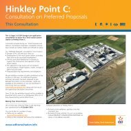


![6.3 - Safety Injection System (RIS [SIS]) - EDF Hinkley Point](https://img.yumpu.com/42739985/1/184x260/63-safety-injection-system-ris-sis-edf-hinkley-point.jpg?quality=85)