
You also want an ePaper? Increase the reach of your titles
YUMPU automatically turns print PDFs into web optimized ePapers that Google loves.
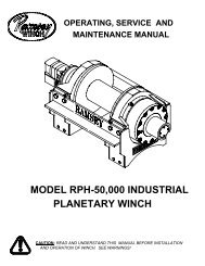
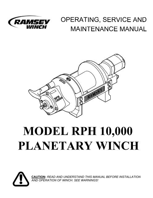
CAUTION: READ AND UNDERSTAND THIS MANUAL BEFORE INSTALLATIONAND OPERATION OF WINCH. SEE WARNINGS!
TABLE OF CONTENTSINTRODUCTIONS 1WARRANTY INFORMATION 1SPECIFICATIONS 1WARNINGS 1WINCH MOUNTING 2CABLE INSTALLATION 3HYDRAULIC SYSTEM REQUIREMENTS 4PERFORMANCE CHARTS 4OPERATION 5MANUAL CLUTCH SHIFTER 5AIR CYLINDER CLUTCH SHIFTER 5MAINTENANCE 5TROUBLE SHOOTING GUIDE 6BRAKE ADJUSTMENT 7INSTRUCTIONS FOR OVERHAUL 8-13DIMENSIONAL DRAWINGSRPH 10,000 WITH MANUAL CLUTCH SHIFTER 15RPH 10,000 WITH AIR CYLINDER CLUTCH SHIFTER 16PARTS LIST AND PARTS DRAWINGSRPH 10,000 WITH MANUAL CLUTCH SHIFTER 17-18RPH 10,000 WITH MANUAL CLUTCH SHIFTER & CLUTCH ENGAGEMENT INDICATOR LIGHT 19-20RPH 10,000 WITH AIR CYLINDER CLUTCH SHIFTER 21-221RPH 10,000 WITH BLOCKED CLUTCH 23-24LIMITED WARRANTYBACK COVER
RAMSEY HYDRAULIC PLANETARY WINCH MODEL RPH-10,000PLEASE READ THIS MANUAL CAREFULLYThis manual contains useful ideas in obtaining the most efficient operation from your <strong>Ramsey</strong> <strong>Winch</strong>, and safetyprocedures one needs to know before operating a <strong>Ramsey</strong> <strong>Winch</strong>. Do not operate this winch until you havecarefully read and understand the "WARNING" and "OPERATION" sections of this manual.WARRANTY INFORMATION<strong>Ramsey</strong> <strong>Winch</strong>es are designed and built to exacting specifications. Great care and skill go into every winch wemake. If the need should arise, warranty procedure is outlined on the back of your self-addressed postage paidwarranty card. Please read and fill out the enclosed warranty card and send it to <strong>Ramsey</strong> <strong>Winch</strong> Company. Ifyou have any problems with our winch, please follow instructions for prompt service on all warranty claims.Refer to back page for limited warranty.SPECIFICATIONS*NOTE: The rated line pulls shown are for the winch only. Consult the wire rope manufacturer for wire rope ratings.WARNINGS:CLUTCH MUST BE FULLY ENGAGED BEFORE STARTING THE WINCH.DO NOT DISENGAGE CLUTCH UNDER LOAD.DO NOT LEAVE CLUTCH ENGAGED WHEN WINCH IS NOT IN USE.STAY OUT FROM UNDER AND AWAY FROM RAISED LOADS.STAND CLEAR OF CABLE WHILE PULLING. DO NOT TRY TO GUIDE CABLE.DO NOT EXCEED MAXIMUM LINE PULL RATINGS SHOWN IN TABLE.DO NOT USE WINCH TO LIFT, SUPPORT, OR OTHERWISE TRANSPORT PERSONNEL.A MINIMUM OF 5 WRAPS OF CABLE AROUND THE DRUM BARREL IS NECESSARY TO HOLD THELOAD. CABLE CLAMP (SETSCREW) IS NOT DESIGNED TO HOLD LOAD.IN CAR CARRIER APPLICATIONS, AFTER PULLING VEHICLE ON CARRIER, BE SURE TO SECUREVEHICLE TO CARRIER BED. DO NOT MAINTAIN LOAD ON WINCH CABLE WHILE TRANSPORTINGVEHICLE. DO NOT USE WINCH AS A TIE DOWN.WHEN PULLING A HEAVY LOAD PLACE A BLANKET, JACKET, OR TARPAULIN OVER THE CABLEFIVE OR SIX FEET FROM THE HOOK.AVOID CONDITIONS WHERE LOAD SHIFTS OR JERKS OCCUR, AS THEY MAY INDICATE ADANGEROUS SITUATION.1
WINCH MOUNTINGESSENTIAL MOUNTING INSTRUCTIONS TO MAINTAIN ALIGNMENT OF PLANETARY WINCHCOMPONENTSIt is most important that this winch be mounted securely so that the three major sections (the motorend, the cable drum and the gear-housing end) are properly aligned. Excessive bushing wear anddifficulty in freespooling are usually symptoms of misalignment.In the as-installed condition, if the winch is mid mounted then at least one tie plate must be attached tothe mounting feet at the bottom of the winch to maintain alignment. NOTE: If the winch is foot mountedthen at least one tie plate must remain mounted at mid point of winch to maintain alignment. It isalways desirable to use both tie plates in the final installed configuration.Angle Mounting Kit, #251006 ("STD." drum) and #251007 ("Y" drum), is recommended for maximumease in mounting the winch. The angle kit will allow the winch to be mounted in upright or midmountapplications and will meet the criteria of serving as a solid and true mounting surface.When mounting the winch with other than the recommended <strong>Ramsey</strong> Angle Kit, the mounting holepatterns described on page 14 must be used. The mounting surface must be flat within .015 inch andsufficiently stiff to resist flexing. If a steel plate is used for foot mounting it should be .750 inch thick.For this mounting application eight (8) 1/2-13NC x 1-1/2 Lg. Gr. 5 capscrews with lockwashers will beneeded to mount winch. Capscrews should be torqued to 85 ft. lb. (115 Nm.).NOTE: If angles or a steel plate are used in mounting winch, tie plates provided with winch are to beattached to the remaining mounting pads, whether they be side or foot.*CAUTION: If longer bolts (minimum Grade 5) are substituted to mount winch or to mount a roller guide atthe side mount pads, bolt length must be such as to allow a maximum of .50 inch thread lengthengagement in the tapped holes in sides of each end bearing. Refer to page 15. Use of excessive lengthbolts will damage the winch and prevent free spool of the drum. Torque bolts to 55 ft.lbs. (75 Nm).2
CABLE INSTALLATIONA decal on the top of the end bearing indicates the spooling direction of the cable. Also, a letter “A” or“B” is stamped in the end bearing on the brake end indicating rotation. If the decal is damaged orunreadable, contact Customer Service for additional instructions to determine proper direction.1. Unwind cable by rolling it out along the ground to prevent kinking. Securely wrap end of cable,opposite hook, with plastic or similar tape to prevent fraying.2. Place taped end of cable into hole in cable drum, as shown below. Use 3/8-16NC x 1/2 lg. Hx. Soc.drive setscrew (part of 234168 "Y" drum ass'y. & 234169 "STD." drum ass'y.) to secure cable todrum.3. Carefully run winch in the "reel-in" direction. Keeping tension on end of cable, spool all the cableonto the cable drum, taking care to form neatly wrapped layers.After installing cable, check freespool operation. Disengage clutch and pull on cable at a walkingspeed. If cable "Birdnests", loosen jam nut (item #27) and turn nylon screw (item #22) clockwise toincrease drag on drum. If cable pull is excessive loosen nylon setscrew by turning counterclockwise.Tighten jam nut when proper setting is obtained. CAUTION: Over-tightening of jam nut may stripnylon setscrew.3
HYDRAULIC SYSTEM REQUIREMENTSRefer to the performance charts below to properly match your hydraulic system to the winch performance. Thecharts consist of: (1) line pull (LB) first layer vs. working pressure (PSI) and (2) line speed, first layer (FPM) vs.flow (GPM). STATIC (solid line) refers to hoisting a suspended load from rest; DYNAMIC (dotted line) refers tomaintaining the motion of a moving load. A cylinder spool directional control valve is recommended.SYSTEM REQUIREMENTS:2100 PSI RELIEF VALVE SETTING15 GPM FLOW RATE*10 MICRON NOMINAL FILTRATION*CAUTION: DO NOT EXCEED 20 GPM. IF EXCEEDED, MOTOR AND WINCH MAY BE DAMAGED.PERFORMANCE CHARTS4
OPERATIONThe best way to get acquainted with how your winch operates is to make test runs before you actually use it. Planyour test in advance. Remember that you hear your winch, as well as see it operate. Get to recognize the soundsof a light steady pull, a heavy pull, and sounds caused by load jerking or shifting. Avoid conditions where loadshifts or jerks occur, as they may indicate a dangerous situation.The uneven spooling of cable, while pulling a load, is not a problem, unless there is a cable pileup on one end ofdrum. If this happens, reverse the winch to relieve the load and move your anchor point further to the center of thevehicle. After the job is done you can unspool and rewind for a neat lay of the cable.When pulling a heavy load, place a blanket, jacket or tarpaulin over the cable about five or six feet behind thehook. In the event of a broken cable, this will slow the snap back of the cable and could prevent serious injury.The winch clutch allows rapid unspooling of the cable, from cable drum, for hooking onto the load. The clutch isoperated by the clutch shifter lever or air shifter.WARNING: DO NOT DISENGAGE CLUTCH UNDER LOAD.MANUAL CLUTCH SHIFTER (Refer to page 14)TO DISENGAGE CLUTCH: Run the winch in the reverse (reel out) direction until load is off the cable. Pull handleout and rotate 90 o . With handle in the "DISENGAGED" position cable may now be free-spooled from drum.TO ENGAGE CLUTCH: Pull handle out, rotate 90 o and release handle. Run the winch in reverse until the clutchhandle snaps fully into the "ENGAGED" position. DO NOT attempt to pull a load unless the handle is fully at the"ENGAGED" position. If manual shift indicator light is present, the green light is lit when clutch is fully"ENGAGED". DO NOT attempt to pull a load unless the green light is lit. To hookup light to the vehicle electricalsystem refer to the Electrical Schematic on page 15.AIR CYLINDER CLUTCH SHIFTER (Refer to page 15)TO DISENGAGE CLUTCH: Run the winch in the reverse (reel out) direction until load is off the cable. Apply airpressure to the .125-27 NPT port: 80 PSI (min.), 150 PSI (max.). CAUTION: Pressure must not exceed 150PSI.TO ENGAGE CLUTCH: Remove air pressure from the cylinder (a return spring engages the plunger). Run winchin reverse until the clutch engagement indicator light (green light) is lit. DO NOT attempt to pull a load unless thegreen light is lit. To hookup light to the vehicle electrical system refer to the Electrical Schematic on page 15.MAINTENANCE1. Inspect the cable for damage and lubricate frequently. If the cable becomes frayed with broken strands,replace immediately. Cable and hook assembly (75' lg. cable) P/N 524133 ("Y" drum) or (100' lg. cable) P/N524134 ("STD" drum) may be purchased from a <strong>Ramsey</strong> distributor.2. Check that the clutch is fully engaging. See OPERATION instructions, above, for the appropriate clutch shifter.FOR MANUAL CLUTCH ONLY: Monthly disengage clutch, put several drops of oil on the shaft and workclutch IN and OUT several times to lubricate inside of clutch cylinder3. Check brake for drift. Refer to page 7.4. Check oil level of winch brake housing every month. Remove oil level plug (refer to pg.13). Oil level should bekept up to oil level hole (plus or minus 1/8"). Replace oil annually or more often if winch is used frequently.Use 1/2 pint of Mobilfluid 424, Phillips HG Fluid, Texaco TDH, Shell Oil Co. Donax TD high performancetractor transmission fluid or equivalent, and for quietest operation, add 1/4 fl. oz. of an oil additive (availablefrom the factory).5. Check to see that drum cable does not overrun (BIRDNEST) when freespooling. Refer to page 3.6. Replace drum bushings and seals when seals begin to seep grease. Refer to OVERHAUL INSTRUCTIONS,page 8. Add additional lubricant, Mobilith SHC 007, to gears if required.5
TROUBLE SHOOTING GUIDECONDITIONS POSSIBLE CAUSE CORRECTIONDRUM WILL NOT ROTATE <strong>Winch</strong> not mounted squarely, Check mounting. Refer toAT NO LOAD causing end bearings to bind up drum. WINCH MOUNTING page 2.Brake damaged.Inspect and replace brake.Gears damaged.Inspect and replace damaged gears.-------------------------------------------------------------------------------------------------------------------------------------------------------------------DRUM WILL NOT ROTATE Load greater than rated Refer to Specifications pg.1UNDER LOAD capacity of winch. for line pull rating.Low hydraulic systemCheck pressure. Refer to HYDRAULICpressure. SYSTEMS performance charts pg. 4.<strong>Winch</strong> not mounted squarely,Check mounting. Refer tocausing end bearing to bind WINCH MOUNTING pg. 2.up drum.-------------------------------------------------------------------------------------------------------------------------------------------------------------------WINCH RUNS TOO SLOW Low hydraulic system flow rate. Check flow rate. Refer toHYDRAULIC SYSTEMS flow chart page 4.Motor worn out.Replace motor.-------------------------------------------------------------------------------------------------------------------------------------------------------------------DRUM WILL NOT Clutch not disengaged. Check OPERATION. Refer to page 5.FREESPOOL Check ADJUSTMENT. Refer to page 12.<strong>Winch</strong> not mounted squarely,Check mounting. Refer to WINCHcausing end bearings to bind drum. MOUNTING pg. 2Side-mount bolts (item #18,Check bolt length. Bolt thread MUST NOTPage 17) too long causingengage threaded holes in sides of endbinding of ring gear.bearing by more than the .50 inch threaddepth in the end bearing. Refer to page 15.-------------------------------------------------------------------------------------------------------------------------------------------------------------------OIL LEAKAGE Damaged brake housing Replace gasket. Check for pluggedgasket or breather. breather. Refer to pgs. 8 & 10.Damaged brake hub seal. Replace seal. Refer to pg. 10.-------------------------------------------------------------------------------------------------------------------------------------------------------------------OIL LEAKAGE FROM Breather below oil level. Check oil level.BREATHER PLUG-------------------------------------------------------------------------------------------------------------------------------------------------------------------LOADS DRIFT Brake needs adjusting. Adjust brake. Refer to pg. 7.-------------------------------------------------------------------------------------------------------------------------------------------------------------------CABLE BIRDNESTS WHEN Drag screw improperly Adjust nylon drag screw.CLUTCH IS DISENGAGED adjusted. Refer to pg. 3.-------------------------------------------------------------------------------------------------------------------------------------------------------------------EXCESSIVE NOISE Brake torque too high. Reduce torque. Refer to page 7.Hydraulic system flow too highBrake oil level low.Check flow rate. Refer to HYDRAULICSYSTEMS flow chart pg. 4.Check oil level, add oil if necessary.Drum in bind, winch notCheck mounting. Refer tomounted squarely. WINCH MOUNTING pg. 2-------------------------------------------------------------------------------------------------------------------------------------------------------------------DRUM CHATTERS, Low hydraulic system flow. Check flow rate. Refer to HYDRAULICin "REEL IN" direction SYSTEMS flow chart pg. 4.Low hydraulic systemCheck relief valve setting. Refer torelief pressure setting. HYDRAULIC SYSTEMS pg. 4.6
ADJUSTING THE BRAKEAll parts of the oil-cooled automatic safety brake are bathed in oil. When the brake wears tothe point that the load begins to drift, the brake can be adjusted as follows:1. Loosen the lock nut on the adjusting screw (see drawing on page 10).2. Increase the brake torque by turning the adjusting screw clockwise. CAUTION: Only1/4 turn is usually required to adjust the brake. Over-tightening can causeoverheating, and damage to the brake parts. Tighten the lock nut after adjustment iscompleted.If the brake does not respond to adjustment, then a new flat spring (item #3) and/or brakediscs (item #32) may be needed.Brake torque can be checked/set as follows: A torque wrench can be equipped with aspecial adapter to fit the input coupling of the winch. The adapter can be made by welding a1" dia. straight motor shaft, with 1/4" key, in a 1" hex. socket, as shown in the followingfigure.This special adapter will fit into the motor shaft coupling. Place coupling onto drum shaft inwinch. Turn the torque wrench so that the drum turns in the "CABLE OUT" direction(lowering direction). The torque setting for the brake should be 155 to 160 ft. lbs. If thetorque wrench does not show the proper torque value, the adjusting screw should beadjusted 1/4 turn (clockwise if torque is low or counter-clockwise if torque is high). Each timethe adjusting bolt is turned, check the torque reading. Continue this procedure until theproper torque reading is achieved. Then tighten the lock nut. If proper adjustment cannot bemade, follow overhaul instructions on page 10.After the brake has been adjusted to the proper torque setting, as described above,disengage clutch. Start vehicle engine and run winch in the "CABLE IN" (raise direction).Allow winch to run in this direction for one minute.Place your hand on the brake housing. If housing is not hot to the touch then run winch inthe reverse direction (cable out) for one minute. Brake housing should begin to heat.When these conditions exist, proper installation has been made.7
INSTRUCTIONS FOR OVERHAUL OF RAMSEY WINCHMODEL RPH-10,000DISASSEMBLYRemove breather plug and reducer (item #34 & #39) from winch. Drain oil from winch byremoving plug (item #40). Remove motor (item #35), coupling (item #31) from winch byunscrewing capscrews (item #24). If coupling is being replaced, be sure spirol pin isinstalled. Tap motor lightly to disengage. Replace all o-rings and seals with new onesduring re-assembly (order kit #246042). If necessary, remove valve (item #49) from motorby removing capscrews (item #21) and lockwashers (item #51)8
Remove tie plates (item #13) from end bearings (items #7 & #8) by unscrewing capscrews(item #18), as shown. Slide motor end bearing (item #7) from drum (item #1) and drumfrom gear housing end bearing (item #8). Remove input shaft (item #12) from end bearing.Inspect teeth of gear (item #5) for signs of wear. If necessary replace gear by removingsnap ring (item #47) and thrust washer (item #50). Slide new gear over splines of shaftand against snap ring on shaft. Re-install thrust washer and place snap ring into groove ofshaft.9
Remove brake housing (item #9) from end bearing (item #8) by unscrewing (4) capscrews(item #23). Remove plate (item #12) and light assembly, if present. Remove gasket (item#33), coil spring (item #48), flat spring (item #3), retainer plate (item #11), compositionbrake discs (item #32) and cam plate (item #4). Remove hub (item #10) and brake shaft(item #55) with plug (item #42)-which is press-fitted in the hub I.D. Inspect the seal (item#37), inside of gear housing bore, and replace if necessary.Inspect brake discs. Discs are 1/4" thick when new, replace if thinner than .200 in. thick or ifsurfaces are glazed or burnt. Inspect the flat ground surfaces of the cam plate and retainerplate for glazing, warpage or other damage. Glazing can be removed by scraping carefully.Inspect flat spring. It should be bowed at least 1/8". Replace spring if bowed less than 1/8".Replace all worn or damaged parts as needed. Reassemble all parts as shown. Be sureballs are secure between cam plate and hub.Install brake housing, making sure that ends of capscrews (item #17) go through notches inend of flat springs and holes in the retainer plate. Secure brake housing and plate (item#12), if present, to end bearing using capscrews (item #23). Tighten capscrews to 30-40FT.LBS.INDICATOR LIGHT ASSEMBLYIf light is not functioning, remove light (item #2) and apply 12v DC (+) to test. If necessary,remove the switch (item #52). The terminals are normally closed. With ball depressed, theswitch should be open. Replace light and/or switch, as needed.10
Remove o-ring (item #36) and bushing (item #15) from motor end bearing (item #7). Pressnew bushing onto end bearing and dip o-ring in oil and seat into groove of end bearing.Remove seal (item #45) from gear housing end bearing (item #8). Loosen nut (item #27)and remove nylon setscrew (item #22) and remove ring gear (item #6) from gear housingend bearing, if necessary. Remove bushing (item #16) from gear housing end bearing (item#8). Press new bushing (item #16) into place in end bearing. Install ring gear and nylonsetscrew and nut. Ring gear must be fully seated in gear housing end bearing (item #8) andslot in ring gear must NOT be aligned with clutch shifter hole. Install new seal in gearhousing end bearing, with sharp edge of seal outward.11
Generously apply grease (MOBILITH SHC 007) to teeth of ring gear (item #6), teeth of planet gears in drum(item #1) and to bushing in end bearings (item #7 & #8). Apply grease to teeth of gear (item #5) and to splinesof shaft (item #12). Place splined end of shaft into splines of hub in brake housing end bearing (item #8). Placedrum over shaft and rotate drum to engage planet gears with output gear on shaft and ring gear in endbearing.Assemble end bearing to drum assembly and use tie plates (item #13) and capscrews (item #18) to hold bothend bearings together. Tighten capscrews to 55 Ft. Lbs. (75 Nm.). If necessary, remove and replaceappropriate shifter assembly (item #2 or #3), as follows:MANUAL CLUTCH SHIFTER ASSEMBLYRemove by loosening setscrew (item #25), jam nut and unscrewing clutch shifter. Be sure slot in ring gear isnot aligned with clutch shifter hole. Rotate drum, if necessary, to insure hole and slot are not aligned. Reinstallclutch shifter with plunger, jam nut and handle positioned in cylinder housing, as shown. Thread assembly(with handle engaged in cylinder slot) into the end bearing. Pull drum toward the brake housing end bearing toremove play. Hold drum in the position and continue threading the shifter assembly in until the gap betweenthe end of the handle and cylinder is 7/16 +0 -1/16 inch and handle is in the horizontal position, as shownbelow. NOTE: This gap will vary with drum endplay. With the drum pulled against the gear housing, the gapshould be 3/8 inch. Lightly tighten jam nut. Rotate drum until handle snaps fully into the engaged position. Pullhandle out and rotate 90 o . Verify that drum can be rotated freely (at least one full revolution) with clutch shifterat DISENGEGED position. Securely tighten jam nut while holding the handle. Tighten setscrew securely. Recheckclutch operation as described on page 5.AIR CYLINDER SHIFTER ASSEMBLYRemove by loosening setscrew (item #25), jam nut and unscrewing clutch shifter. To reinstall, thread aircylinder into housing. Install one or two shims (item #49) under cylinder head, if needed, to orient air cylinderport for pneumatic connections. Tighten setscrew. Refer to page 5 and check for proper operation of theclutch.BLOCKED CLUTCHInsert plunger assembly into gear housing bore so it engages into ring gear slot. Pull drum flange toward gearhousing and thread setscrew into housing until it bottoms out and drum starts to move. Back setscrew out 1/2turn and lock in place with jam nut.12
Before installing motor, check brake adjustment (refer to page 7, ADJUSTING THE BRAKE).Place splined end of coupling (item #31), with spirol pin installed, inside of motor end bearinghousing (item #7) and slide over splines on end of input shaft. Place o-ring (item #38) aroundmotor pilot. Mount motor (item #35) to end bearing by aligning key on motor shaft withkeyway in coupling. Be sure that motor mounts flush to end bearing and that o-ring is setsecurely in place between motor and end bearing. Secure motor to end bearing using twocapscrews and lockwashers (items #24 & #30). Tighten capscrews to 49 Ft. Lbs. (66 Nm).Thread plug (item #40) into bottom of brake housing. Permatex can be added to threads ofplug to help in sealing. Pour 1/2 pint of Mobilfluid 424, Phillips HG Fluid, Texaco TDH, ShellOil Co. Donax TD high performance tractor transmission fluid, or equivalent, into oil levelhole. Oil level should be kept at oil level hole (plus or minus 1/8"). Thread plug (item #40) intooil level hole. Insert reducer (item #39) into hole in top of brake housing and breather plug(item #34) into reducer. Tighten plugs and reducer securely.13
PARTS LIST RPH-10,000 WITH MANUAL CLUTCH SHIFTERITEM QTY. PART NO. DESCRIPTION1 1 234168 DRUM ASS'Y. "Y"1 234169 DRUM ASS'Y. "STD."2 1 276048 SHIFTER ASS'Y.3 1 306035 SPRING-FLAT, BRK.*4 1 314017 CAM PLATE-“A” ROTATION1 314018 CAM PLATE- “B” ROTATION5 1 334174 GEAR-OUTPUT, SUN6 1 444084 GEAR-RING**7 1 338329 END BEARING-MOTOR**8 1 338327 HOUSING-GEAR, END BEARING**9 1 338328 HOUSING-BRAKE*10 1 314019 HUB PLATE11 1 352021 RETAINER PLATE12 1 357494 SHAFT-INPUT "Y"1 357495 SHAFT-INPUT "STD."13 2 395163 TIE PLATE "Y"2 395172 TIE PLATE "STD."*14 3 400007 BALL15 1 412084 BUSHING-DRUM, MOTOR END16 1 412085 BUSHING-DRUM, GEAR17 2 414273 BOLT-3/8-16NC X 1-3/4, HX, GR. 518 8 414581 CAPSCREW-1/2-13NC X 3/4 LG. HX. HD., GR. 5, Z/P19 1 414622 BOLT-1/2-13NC X 2-1/4, HX. HD., GR. 5, ALL-THD.20 2 414836 CAPSCREW-1/4-20NC X 1/2, HX. SOC. HD.21 4 414159 CAPSCREW-5/16-18NC X 2-1/2, HX. HD., GR5, Z/P22 1 414926 SETSCREW-3/8-16NC X 1, SOCKET, NYLON23 4 414934 CAPSCREW-3/8-16NC X 2-3/4, HX. SOC. HD.24 2 414952 CAPSCREW-1/2-13NC X 1-1/2, SOC. HD.25 1 416016 SETSCREW-1/4-20NC X 1/4 HX. SOC. HD.*26 4 418034 NUT 3/8-16NC HEX.REG.27 1 418036 NUT 3/8-16NC HEX. JAM28 1 418061 NUT-1/2-13NC HEX. JAM29 4 418184 WASHER-3/8 ID X 5/8 OD X 1/16 FLAT ALUM30 2 418218 LOCKWASHER-1/2 ID MED. SECT.31 1 299713 COUPLING-HYD. MOTOR32 2 438018 PLATE-BRAKE33 1 442212 GASKET-BRK. HSG.34 1 456008 RELIEF FITTING35 1 458079 MOTOR-HYD.36 1 462046 O-RING37 2 462047 QUAD-RING38 1 462048 O-RING39 1 468002 REDUCER40 2 468018 PIPE PLUG*41 1 340077 BRAKE SHAFT*42 1 472051 PLUG43 1 472052 PLUG44 1 486076 SEAL45 1 486080 SEAL-GEAR HSG.46 1 518037 SHIM47 2 490003 SNAP RING48 1 494010 SPRING49 1 516008 VALVE-COUNTERBALANCE ("A" ROTATION)1 516009 VALVE-COUNTERBALANCE ("B" ROTATION)50 1 518047 WASHER-THRUST51 4 418163 LOCKWASHER – 5/16 MED SECT Z/P* EFFECTIVE SERIAL NUMBER: 2038147** EFFECTIVE DATE CODE: H0770204116
PARTS LIST RPH-10,000 WITH MANUAL CLUTCH SHIFTER AND CLUTCH ENGAGEMENT INDICATOR LIGHTITEM QTY. PART NO. DESCRIPTION1 1 234168 DRUM ASS'Y. "Y"1 234169 DRUM ASS'Y. "STD."2 1 236020 LIGHT ASS'Y.3 1 276048 SHIFTER ASS'Y.4 1 306035 SPRING-FLAT, BRK.*5 1 314017 CAM PLATE-“A” ROTATION1 314018 CAM PLATE-“B” ROTATION6 1 334174 GEAR-OUTPUT, SUN7 1 444084 GEAR-RING**8 1 338329 END BEARING-MOTOR**9 1 338327 HOUSING-GEAR, END BEARING**10 1 338328 HOUSING-BRAKE*11 1 314019 HUB PLATE12 1 350598 PLATE-LIGHT MTG.13 1 352021 RETAINER PLATE14 1 357494 SHAFT-INPUT "Y"1 357495 SHAFT-INPUT "STD."15 2 395163 TIE PLATE "Y"2 395172 TIE PLATE "STD."*16 3 400007 BALL17 1 412084 BUSHING-DRUM, MOTOR END18 1 412085 BUSHING-DRUM, GEAR19 2 414273 BOLT-3/8-16NC X 1-3/4, HX, GR. 520 8 414581 CAPSCREW-1/2-13NC X 3/4 LG. HX. HD., GR. 5, Z/P21 1 414622 BOLT-1/2-13NC X 2-1/4, HX. HD., GR. 5, ALL-THD.22 2 414836 CAPSCREW-1/4-20NC X 1/2, HX. SOC. HD.23 4 414159 CAPSCREW-5/16-18NC X 2-1/2, HX. HD., GR5, Z/P24 1 414926 SETSCREW-3/8-16NC X 1, SOCKET, NYLON25 4 414934 CAPSCREW-3/8-16NC X 2-3/4, HX. SOC. HD.26 2 414952 CAPSCREW-1/2-13NC X 1-1/2, SOC. HD.27 1 416016 SETSCREW-1/4-20NC X 1/4 HX. SOC. HD.**28 4 418034 NUT 3/8-16NC HEX.REG.29 1 418036 NUT 3/8-16NC HEX. JAM30 1 418061 NUT-1/2-13NC HEX. JAM31 4 418184 WASHER-3/8 ID X 5/8 OD X 1/16 FLAT ALUM32 2 418218 LOCKWASHER-1/2 ID MED. SECT.33 1 299713 COUPLING-HYD. MOTOR34 2 438018 PLATE-BRAKE35 1 442212 GASKET-BRK. HSG.36 1 456008 RELIEF FITTING37 1 458079 MOTOR-HYDRAULIC38 1 462046 O-RING39 2 462047 QUAD-RING40 1 462048 O-RING41 1 468002 REDUCER42 2 468018 PIPE PLUG*43 1 340077 BRAKE SHAFT*44 1 472051 PLUG45 1 482013 GROMMET46 1 482045 RUBBER BOOT47 1 486076 SEAL48 1 486080 SEAL-GEAR HSG.49 2 490003 SNAP RING50 1 494010 SPRING51 1 504021 SWITCH ASS'Y.52 1 516008 VALVE-COUNTERBALANCE ("A" ROTATION)1 516009 VALVE-COUNTERBALANCE ("B" ROTATION)53 1 518047 WASHER-THRUST54 4 418163 LOCKWASHER – 5/16 MED SECT Z/P* EFFECTIVE SERIAL NUMBER: 2038147** EFFECTIVE DATE CODE: H0770204118
PARTS LIST RPH-10,000 WITH AIR-CYLINDER CLUTCH SHIFTERITEM QTY. PART NO. DESCRIPTION1 1 234168 DRUM ASS'Y. "Y"1 234169 DRUM ASS'Y. "STD."2 1 236020 LIGHT ASS'Y.3 1 276049 SHIFTER ASS'Y.-AIR4 1 306035 SPRING-FLAT, BRK.*5 1 314017 CAM PLATE-“A” ROTATION1 314018 CAM PLATE-“B” ROTATION6 1 334174 GEAR-OUTPUT, SUN7 1 444084 GEAR-RING**8 1 338329 END BEARING-MOTOR**9 1 338327 HOUSING-GEAR, END BEARING**10 1 338328 HOUSING-BRAKE*11 1 314019 HUB PLATE12 1 350598 PLATE-LIGHT MTG.13 1 352021 RETAINER PLATE*14 1 357494 SHAFT-INPUT "Y"1 357495 SHAFT-INPUT "STD."15 2 395163 TIE PLATE "Y"2 395172 TIE PLATE "STD."16 3 400007 BALL17 1 412084 BUSHING-DRUM, MOTOR END18 1 412085 BUSHING-DRUM, GEAR19 2 414273 BOLT-3/8-16NC X 1-3/4, HX, GR. 520 8 414581 CAPSCREW-1/2-13NC X 3/4 LG. HX. HD., GR. 5, Z/P21 1 414622 BOLT-1/2-13NC X 2-1/4, HX. HD., GR. 5, ALL-THD.22 2 414836 CAPSCREW-1/4-20NC X 1/2, HX. SOC. HD.23 4 414159 CAPSCREW-5/16-18NC X 2-1/2, HX. HD., GR. 5, Z/P24 1 414926 SETSCREW-3/8-16NC X 1, SOCKET, NYLON25 4 414934 CAPSCREW-3/8-16NC X 2-3/4, HX. SOC. HD.26 2 414952 CAPSCREW-1/2-13NC X 1-1/2, SOC. HD.27 1 416016 SETSCREW-1/4-20NC X 1/4 HX. SOC. HD.**28 4 418034 NUT 3/8-16NC HEX.REG.29 1 418036 NUT 3/8-16NC HEX. JAM30 1 418061 NUT-1/2-13NC HEX. JAM31 4 418184 WASHER-3/8 ID X 5/8 OD X 1/16 FLAT ALUM32 2 418218 LOCKWASHER-1/2 ID MED. SECT.33 1 299713 COUPLING-HYD. MOTOR34 2 438018 PLATE-BRAKE35 1 442212 GASKET-BRK. HSG.36 1 456008 RELIEF FITTING37 1 458079 MOTOR-HYDRAULIC38 1 462046 O-RING39 2 462047 QUAD-RING40 1 462048 O-RING41 1 468002 REDUCER42 2 468018 PIPE PLUG*43 1 340077 BRAKE SHAFT*44 1 472051 PLUG45 1 482013 GROMMET46 1 482045 RUBBER BOOT47 1 486076 SEAL48 1 486080 SEAL-GEAR HSG.49 2 488007 SHIM50 2 490003 SNAP RING51 1 494010 SPRING52 1 504021 SWITCH ASS'Y.53 1 516008 VALVE-COUNTERBALANCE ("A" ROTATION)1 516009 VALVE-COUNTERBALANCE ("B" ROTATION)54 1 518047 WASHER-THRUST55 4 418163 LOCKWASHER – 5/16 MED SECT Z/PEFFECTIVE SERIAL NUMBER: 2038147EFFECTIVE DATE CODE: H0770204120
PARTS LIST RPH-10,000 WITH BLOCKED CLUTCHITEM QTY. PART NO. DESCRIPTION1 1 234169 DRUM ASS'Y. "STD."2311299693306035PLUNGER ASSEMBLYSPRING-FLAT, BRK.*4 1 314017 CAM PLATE-“A” ROTATION511314018334174CAM PLATE-“B” ROTATIONGEAR-OUTPUT, SUN6 1 444084 GEAR-RING**7**811338329338327END BEARING-MOTORHOUSING-GEAR, END BEARING**9 1 338328 HOUSING-BRAKE*101111314019352021HUB PLATERETAINER PLATE12 1 357495 SHAFT-INPUT "STD."13*1423395172400007TIE PLATE "STD."BALL15 1 412084 BUSHING-DRUM, MOTOR END161712412085414273BUSHING-DRUM, GEARBOLT-3/8-16NC X 1-3/4, HX, GR. 518 8 414581 CAPSCREW-1/2-13NC X 3/4 LG. HX. HD., GR. 5, Z/P192012414622414836BOLT-1/2-13NC X 2-1/4, HX. HD., GR. 5, ALL-THD.CAPSCREW-1/4-20NC X 1/2, HX. SOC. HD.21 4 414159 CAPSCREW 5/16-18NC X 2-1/2 LG. HX.HD. GR. 5, Z/P222314414926414934SETSCREW-3/8-16NC X 1, SOCKET, NYLONCAPSCREW-3/8-16NC X 2-3/4, HX. SOC. HD.24 2 414952 CAPSCREW-1/2-13NC X 1-1/2, SOC. HD.252611416016416080SETSCREW-1/4-20NC X 1/4 HX. SOC. HD.SETSCREW 5/8-18NF X 1 HX. SOC. DRIVE*27 4 418034 NUT 3/8-16NC HEX.REG.282911418036418061NUT 3/8-16NC HEX. JAMNUT-1/2-13NC HEX. JAM30 1 418088 NUT-JAM 5/8-18NF HX. Z/P313242418184418218WASHER-3/8 ID X 5/8 OD X 1/16 FLAT ALUMLOCKWASHER-1/2 ID MED. SECT.33 1 299713 COUPLING-HYD. MOTOR343521438018442212PLATE-BRAKEGASKET-BRK. HSG.36 1 456008 RELIEF FITTING373811458079462046MOTOR-HYD.O-RING39 2 462047 QUAD-RING404111462048468002O-RINGREDUCER42 2 468018 PIPE PLUG*43*4411340077472051BRAKE SHAFTPLUG45 1 472052 PLUG464711486076486080SEALSEAL-GEAR HSG.48 2 490003 SNAP RING495011494010516008SPRINGVALVE-COUNTERBALANCE ("A" ROTATION)1 516009 VALVE-COUNTERBALANCE ("B" ROTATION)515211518037518047SHIMWASHER-THRUST53 4 418163 LOCKWASHER – 5/16 MED SECT Z/PEFFECTIVE SERIAL NUMBER: 2038147EFFECTIVE DATE CODE: H0770204122
NOTES
NOTES
LIMITED WARRANTYRAMSEY WINCH warrants each new RAMSEY <strong>Winch</strong> to be free from defects in material and workmanshipfor a period of one (1) year from date of purchase.The obligation under this warranty, statutory or otherwise, is limited to the replacement or repair at theManufacturer's factory, or at a point designated by the Manufacturer, of such part that shall appear to theManufacturer, upon inspection of such part, to have been defective in material or workmanship.This warranty does not obligate RAMSEY WINCH to bear the cost of labor or transportation charges inconnection with the replacement or repair of defective parts, nor shall it apply to a product upon whichrepair or alterations have been made, unless authorized by Manufacturer, or for equipment misused,neglected or which has not been installed correctly.RAMSEY WINCH shall in no event be liable for special or consequential damages. RAMSEY WINCHmakes no warranty in respect to accessories such as being subject to the warranties of their respectivemanufacturers.RAMSEY WINCH, whose policy is one of continuous improvement, reserves the right to improve itsproducts through changes in design or materials as it may deem desirable without being obligated toincorporate such changes in products of prior manufacture.If field service at the request of the Buyer is rendered and the fault is found not to be with RAMSEYWINCH's product, the Buyer shall pay the time and expense to the field representative. Bills for service,labor or other expenses that have been incurred by the Buyer without approval or authorization byRAMSEY WINCH will not be acceptedSee warranty card for details.RAMSEY WINCH COMPANYPost Office Box 581510 Tulsa, Oklahoma 74158-1510Telephone: (918) 438-2760 FAX: (918) 438-6688OM-912465-1102-N