Create successful ePaper yourself
Turn your PDF publications into a flip-book with our unique Google optimized e-Paper software.
OPERATING, SERVICE ANDMAINTENANCE MANUALCAUTION: READ AND UNDERSTAND THIS MANUAL BEFORE INSTALLATIONAND OPERATION OF WINCH. SEE WARNINGS!
TABLE OF CONTENTSINTRODUCTIONS........................................................................................................................1WARRANTY INFORMATION .......................................................................................................1SPECIFICATIONS........................................................................................................................1WARNINGS. ................................................................................................................................1WINCH MOUNTING.....................................................................................................................2CABLE INSTALLATION ...............................................................................................................3HYDRAULIC SYSTEM REQUIREMENTS ...................................................................................4PERFORMANCE CHARTS ..........................................................................................................4OPERATIONS ..............................................................................................................................5MANUAL CLUTCH SHIFTER.......................................................................................................5MAINTENANCE ...........................................................................................................................5TROUBLE SHOOTING GUIDE ....................................................................................................6INSTRUCTIONS FOR OVERHAUL .............................................................................................7-12DIMENSIONAL DRAWINGSRPH 12,000 WITH MANUAL CLUTCH SHIFTER...................................................13RPH 12,000 WITH AIR CYLINDER CLUTCH SHIFTER.........................................14PARTS LIST AND PARTS DRAWINGSRPH 12,000 WITH MANUAL CLUTCH SHIFTER...................................................16-17RPH 12,000 WITH AIR CYLINDER CLUTCH SHIFTER.........................................18-19RPH 12,000 WITH BLOCKED CLUTCH.................................................................20-21LIMITED WARRANTY..................................................................................................................22
RAMSEY HYDRAULIC PLANETARY WINCH MODEL RPH 12,000PLEASE READ THIS MANUAL CAREFULLYThis manual contains useful ideas for obtaining the most efficient operation from your <strong>Ramsey</strong><strong>Winch</strong>, and safety procedures one needs to know before operating a <strong>Ramsey</strong> <strong>Winch</strong>. Do notoperate this winch until you have carefully read and understand the "WARNING" and"OPERATION" sections of this manual.WARRANTY INFORMATION<strong>Ramsey</strong> <strong>Winch</strong>es are designed and built to exacting specifications. Great care and skill go intoevery winch we make. If the need should arise, warranty procedure is outlined on the back ofyour self-addressed postage paid warranty card. Please read and fill out the enclosed warrantycard and send it to <strong>Ramsey</strong> <strong>Winch</strong> Company. If you have any problems with your winch, pleasefollow instructions for prompt service on all warranty claims. Refer to back page for limitedwarranty.SPECIFICATIONS*NOTE: The rated line pulls shown are for the winch only. Consult the wire rope manufacturer for wire rope ratings.WARNINGS:CLUTCH MUST BE FULLY ENGAGED BEFORE STARTING THE WINCH.DO NOT DISENGAGE CLUTCH UNDER LOAD.DO NOT LEAVE CLUTCH ENGAGED WHEN WINCH IS NOT IN USE.STAY OUT FROM UNDER AND AWAY FROM RAISED LOADS.STAND CLEAR OF CABLE WHILE PULLING. DO NOT TRY TO GUIDE CABLE.DO NOT EXCEED MAXIMUM LINE PULL RATINGS SHOWN IN TABLE.DO NOT USE WINCH TO LIFT, SUPPORT, OR OTHERWISE TRANSPORT PERSONNEL.A MINIMUM OF 5 WRAPS OF CABLE AROUND THE DRUM BARREL IS NECESSARY TO HOLD THE LOAD.CABLE CLAMP (SETSCREW) IS NOT DESIGNED TO HOLD LOAD.IN CAR CARRIER APPLICATIONS, AFTER PULLING VEHICLE ON CARRIER, BE SURE TO SECURE VEHICLETO CARRIER BED. DO NOT MAINTAIN LOAD ON WINCH CABLE WHILE TRANSPORTING VEHICLE. DONOT USE WINCH AS A TIE DOWN.WHEN PULLING A HEAVY LOAD PLACE A BLANKET, JACKET, OR TARPAULIN OVER THE CABLE FIVE ORSIX FEET FROM THE HOOK.AVOID CONDITIONS WHERE LOAD SHIFTS OR JERKS OCCUR, AS THEY MAY INDICATE A DANGEROUSSITUATION.1
WINCH MOUNTINGESSENTIAL MOUNTING INSTRUCTIONS TO MAINTAIN ALIGNMENT OF PLANETARY WINCH COMPONENTSIt is most important that this winch be mounted securely so that the three major sections (the motor end,the cable drum and the gear-housing end) are properly aligned. Excessive bushing wear and difficulty infreespooling are usually symptoms of misalignment.In the as-installed condition, if the winch is mid mounted at least one tie plate must be attached to themounting feet at the bottom of the winch to maintain alignment. NOTE: If the winch is foot mounted, atleast one tie plate must remain mounted at mid point of winch to maintain alignment. It is always desirableto use both tie plates in the final installed configuration.Angle Mounting Kit, #251006, is recommended for maximum ease in mounting the winch. Theangle kit will allow the winch to be mounted in upright or midmount applications and will meet thecriteria of serving as a solid and true mounting surface.When mounting the winch with other than the recommended <strong>Ramsey</strong> Angle Kit, the mounting holepatterns described on page 14 must be used. The mounting surface must be flat within .015 inchand sufficiently stiff to resist flexing. If a steel plate is used for foot mounting it should be .750inch thick. For this mounting application eight (8) 1/2-13NC x 1-1/2 Lg. Gr. 5 capscrews withlockwashers will be needed to mount winch. Capscrews should be torqued to 85 ft. lb. (115 Nm.).NOTE: If angles or a steel plate are used in mounting winch, tie plates provided with winch are tobe attached to the remaining mounting pads, whether they be side or foot.*CAUTION: If longer bolts (minimum Grade 5) are substituted to mount winch or to mount a rollerguide at the side mount pads, bolt length must be such as to allow a maximum of .56 inch threadlength engagement in the tapped holes in sides of each end bearing. Refer to page 13. Use ofexcessive length bolts will not allow tie plate to tighten down properly. Torque bolts to 55 ft. lbs. (75Nm).2
CABLE INSTALLATION1. Unwind cable by rolling it out along the ground to prevent kinking. Securely wrap end of cable,opposite hook, with plastic or similar tape to prevent fraying.2. Place taped end of cable into hole in cable drum, as shown below. Use 3/8-16NC x 1/2 lg. Hx.Soc. drive setscrew (part of 234171 drum assembly) to secure cable to drum.3. Carefully run winch in the "reel-in" direction. Keeping tension on end of cable, spool all thecable onto the cable drum, taking care to form neatly wrapped layers.After installing cable, check freespool operation. Disengage clutch and pull on cable at a walkingspeed. If cable "birdnests", loosen jam nut (item #21) and turn nylon screw (item #19) clockwise toincrease drag on drum. If cable pull is excessive loosen nylon setscrew by turning counterclockwise.Tighten jam nut when proper setting is obtained.CAUTION: Over-tightening of jam nut may strip nylon setscrew.3
HYDRAULIC SYSTEM REQUIREMENTSRefer to the performance charts below to properly match your hydraulic system to the winch performance. The chartsconsist of: (1) first layer line pull (LB) vs. working pressure (PSI), (2) first layer line speed (FPM) vs. flow (GPM), and(3) relief valve setting (PSI) vs. flow (GPM). A motor spool directional control valve is required.SYSTEM REQUIREMENTS:2500 PSI RELIEF VALVE SETTING*15 GPM FLOW RATE**10 MICRON NOMINAL FILTRATION*CAUTION: DO NOT EXCEED 20 G.P.M. IF EXCEEDED, MOTOR AND WINCH MAY BE DAMAGEDTYPICAL LAYOUTPERFORMANCE CHARTSPERFORMANCE WITH 24.0 CU. IN. HYDRAULIC MOTOR4
OPERATIONThe best way to get acquainted with how your winch operates is to make test runs before youactually use it. Plan your test in advance. Remember, you hear your winch, as well as see itoperate. Get to recognize the sounds of a light steady pull, a heavy pull, and sounds caused by loadjerking or shifting. Avoid conditions where load shifts or jerks occur, as they may indicate a dangeroussituation.The uneven spooling of cable, while pulling a load, is not a problem, unless there is a cable pileup onone end of drum. If this happens, reverse the winch to relieve the load and move your anchor pointfurther to the center of the vehicle. After the job is done you can unspool and rewind for a neat lay ofthe cable.When pulling a heavy load place a blanket, jacket or tarpaulin over the cable about five or six feetbehind the hook. In the event of a broken cable, this will slow the snap back of the cable and couldprevent serious injury.The winch clutch allows rapid unspooling of the cable from the cable drum for hooking onto the load.The clutch is operated by the clutch shifter lever or air shifter.WARNING: DO NOT DISENGAGE CLUTCH UNDER LOAD.MANUAL CLUTCH SHIFTER (Refer to page 13)TO DISENGAGE CLUTCH: Run the winch in the reverse (reel out) direction until load is off the cable.Pull handle out and rotate 90 o . With handle in the "DISENGAGED" position, cable may now be freespooledfrom drum.TO ENGAGE CLUTCH: Pull handle out, rotate 90 o and release handle. Run the winch in reverse untilthe clutch handle snaps fully into the "ENGAGED" position. DO NOT attempt to pull a load unless thehandle is fully at the "ENGAGED" position.AIR CYLINDER CLUTCH SHIFTER (Refer to page 14)TO DISENGAGE CLUTCH: Run the winch in the reverse (reel out) direction until load is off the cable.Apply air pressure to the .125-27 NPT port: 80 PSI (min.) 150 PSI (max.). CAUTION: Pressure mustnot exceed 150 PSI.TO ENGAGE CLUTCH: Remove air pressure from the cylinder (a return spring engages the plunger).Run winch in reverse until the clutch engagement indicator light (green light) is lit. DO NOT attempt topull a load unless the green light is lit. To connect light to the vehicle electrical system refer to theElectrical Schematic on page 14.MAINTENANCE1. Inspect the cable for damage and lubricate frequently. If the cable becomes frayed with brokenstrands, replace immediately.2. Check that the clutch is fully engaging. See OPERATION instructions, above, for the appropriateclutch shifter. FOR MANUAL CLUTCH ONLY: Monthly disengage clutch, put several drops of oil onthe shaft and work clutch IN and OUT several times to lubricate inside of clutch cylinder.3. Check to see that drum cable does not overrun (birdnest) when freespooling. Refer to page 3.4. Replace drum bushings and seals when seals begin to seep grease. Refer to OVERHAULINSTRUCTIONS, page 7. Add additional lubricant, Mobilith SHC 007, to gears if required.5
TROUBLE SHOOTING GUIDECONDITIONS POSSIBLE CAUSE CORRECTION / ACTIONDRUM WILL NOT ROTATE Brake damaged. Inspect and replace brake.AT NO LOADGears damaged.Inspect and replace damaged gears.Brake not releasingSee section below.DRUM WILL NOT ROTATE Load greater than rated Refer to Specifications pg.1UNDER LOAD capacity of winch. for line pull rating.Low hydraulic systemCheck pressure. Refer to HYDRAULICpressure. SYSTEMS performance charts pg. 4.WINCH RUNS TOO SLOW Low hydraulic system flow rate. Check flow rate. Refer toHYDRAULIC SYSTEMS flow chart page 4.Motor worn out.Replace motor.DRUM WILL NOT Clutch not disengaged. Check clutch shifter. Refer to page 5.FREESPOOL Check ADJUSTMENT. Refer to page 10.BRAKE WILL NOT RELEASE Brake damaged. Inspect and replace. Refer to page 8 & 11 foroverhaul.CABLE BIRDNESTS WHEN Drag screw improperly Adjust nylon drag screw.CLUTCH IS DISENGAGED adjusted. Refer to pg. 3.EXCESSIVE NOISE Hydraulic system flow too high Check flow rate. Refer to HYDRAULICSYSTEMS flow chart pg. 4.DRUM CHATTERS, Low hydraulic system flow. Check flow rate. Refer to HYDRAULICin "REEL IN" direction SYSTEMS flow chart pg. 4.Low hydraulic systemCheck relief valve setting. Refer torelief pressure setting. HYDRAULIC SYSTEMS pg. 4.OIL SEEPAGE FROM Brake piston not sealing properly. Replace o-ring and back up rings on brakeBREATHER VENT OF piston. Refer to page 8 & 11.BRAKE HOUSINGGREASE SEEPAGE FROM Grease applied to seals during NONE. Normal condition during the firstJOINTS IN MOTOR assembly by the motor manufacturer. few times the winch is operated.6
INSTRUCTIONS FOR OVERHAUL OF RAMSEY WINCHMODEL RPH 12,000DISASSEMBLYTake note of mounting configuration for proper mounting of parts during re-assembly.Disconnect tube (item #44) from elbows (item #24) on bottom of brake (item #6) and valve(item #45). Remove motor (item #31) from brake housing (item #6) by unscrewing capscrews(item #15). Tap motor lightly to disengage. Replace all gaskets, o-rings and seals with newones during re-assembly.Remove coupling (item #23) from brake housing. Examine coupling for signs of wear, replaceif necessary. If necessary, remove valve (item #45) from motor by removing capscrews (item#19) and lockwashers (item #49). If valve is removed make sure two square cross section o-rings remain seated in their counter bores in valve.7
Remove brake housing (item #6) from end bearing (item #4) by unscrewing (6) capscrews (item#14) in a criss-cross pattern (2 turns each) until all capscrews are removed from brake housing.Remove brake parts from brake housing. Examine brake discs (item #26) for signs of wear,and replace if necessary. Examine o-rings (items #34 & #35) and backup rings (items #36 %) for signs of wear. Remove o-rings and backup rings from grooves in brake piston (item#3).Remove and examine springs (items #42 & #43) for damage, replace if necessary.Examine fitting (item #30) to assure that fittings are in proper working condition, replace ifnecessary.8
Remove tie plates (item #9) from end bearings (items #4 & #5) by unscrewing capscrews (item#16), as shown. Remove snap ring (item #41) and thrust washer (item #48) from shaft. Slidemotor end bearing (item #4) from drum (item #1) and drum from gear housing end bearing (item#5).Remove input shaft (item #8) and thrust washer (item #47) from end bearing. Inspect gearteeth and splined end of shaft for signs of wear. If damaged, it will be necessary to replaceshaft.Remove o-ring (item #32), bushing (item #12) from outside of motor end bearing (item #4),remove o-ring (item #33), bearing (item #11) from inside of motor end bearing (item #4). Placenew, well oiled, o-ring (item #33) into groove inside of end bearing and press new bearing (item#11) into end bearing. Press bushing (item #12) onto end bearing and dip o-ring (item #32) inoil and seat into groove of end bearing.Remove seal (item #40) from gear housing end bearing (item #5). Loosen nut (item #21) andremove nylon setscrew (item #18) and remove ring gear (item #29) from gear housing endbearing, if necessary. Remove bushing (item #13) and bearing (item #10) from gear housingend bearing (item #5). Press new bushing (item #13) and bearing (item #10) into place in endbearing. Install ring gear and nylon setscrew and nut. Ring gear must be fully seated in gearhousing end bearing (item #5) and slot in ring gear must NOT be aligned with clutch shifter hole.Install new seal in gear housing end bearing, with sharp edge of seal outward.9
Generously apply grease (MOBILITH SHC 007) to teeth of ring gear (item #28), teeth of planet gears indrum (item #1) and to bushing in gear housing end bearing (item #5). Apply a small amount of grease tobase of bushing on motor end bearing (item #4). Apply grease to teeth of gear and short end of shaft(item #8). Place gear end of shaft through thrust washer (item #47) and into bearing in end bearing (item#5). Place drum over shaft and rotate drum to engage planet gears with output gear on shaft and withring gear in end bearing.Assemble end bearing (item #4) to drum assembly and use tie plates (item #9) and capscrews (item #16)to hold both end bearings together. Tighten capscrews to 55 Ft. Lbs. (75 Nm.). Slide thrust washer (item#48) over end of shaft and against end bearing (item #4). Place snap ring (item #41) into groove insplined end of shaft.If necessary, remove and replace appropriate shifter assembly (item #2 or #3), as follows:MANUAL CLUTCH SHIFTER ASSEMBLYRemove by loosening setscrew (item #18), jam nut and unscrewing clutch shifter. Be sure slot in ringgear is not aligned with clutch shifter hole. Rotate drum, if necessary, to insure hole and slot are notaligned. Reinstall clutch shifter with plunger, jam nut and handle positioned in cylinder housing, asshown. Thread assembly (with handle engaged in cylinder slot) into the end bearing. Pull drum towardthe brake housing end bearing to remove play. Hold drum in the position and continue threading theshifter assembly in until the gap between the end of the handle and cylinder is 7/16 +0 -1/16 inch andhandle is in the horizontal position, as shown below. NOTE: This gap will vary with drum endplay. Withthe drum pulled against the gear housing, the gap should be 3/8 inch. Lightly tighten jam nut. Rotatedrum until handle snaps fully into the engaged position. Pull handle out and rotate 90 o . Verify that drumcan be rotated freely (at least one full revolution) with clutch shifter at DISENGAGED position. Securelytighten jam nut while holding the handle. Tighten setscrew securely. Re-check clutch operation asdescribed on page 5.AIR CYLINDER SHIFTER ASSEMBLYRemove by loosening setscrew (item #18), jam nut and unscrewing clutch shifter. To reinstall, thread aircylinder into housing. Install one or two shims (item #45) under cylinder head, if needed, to orient aircylinder port for pneumatic connections. Tighten setscrew. Refer to page 5 and check for properoperation of the clutch.BLOCKED CLUTCHInsert plunger into gear housing bore so it engages into ring gear slot. Pull drum flange toward gearhousing and thread setscrew into housing until it bottoms out and drum starts to move. Back setscrewout 1/2 turn and lock in place with jam nut.10
Set winch on gear housing end with motor end bearing (item #4) up. Insert (6) springs (item #42) into pockets ofmotor end bearing (item #4), as shown, leaving top and bottom pockets empty. Install coupling (item #23) oversplined end of shaft (item #8). Put (4) brake pins (item #7) into (4) holes in motor end bearing. Install well-oiled o-ring (items #34 & #35) and backup rings (items #36 & #37) into grooves in O.D. of piston (item #3). Place o-ringsinto portions of grooves nearest to center of piston in both cases. See SECTION A-A below.Piston (item #3), brake disc (item #26) and separator plates (item #39) must be clean and free of grease and oil.Place piston over pins (item #7) and on top of springs (item #42). Place separator plates (item #39) and brake discalternately on top of piston, as shown below. Press larger diameter end of (4) springs (item #43) into pockets inbrake housing (item #6). Place gasket (item #27) on top of end bearing (item #4). Place brake housing over brakeparts with fitting ports downward toward mounting feet. Align mounting holes and force brake housing down ontoend bearing (item #4). Apply 271 Loc-tite to 6 capscrews (item #14) and finger tighten until flush with surface ofbrake housing. Torque capscrews (2 turns each) in a criss-cross pattern until a torque of 30 ft. lbs., per capscrew, isachieved.11
Place gasket (item #28) into position on mounting surface of motor (item #31). Slide motor shaft into coupling andattach motor to brake housing (item #6). Use (2) capscrews (item #15) with lockwashers (item #22) and torque to 87ft. lbs. (118 Nm) each. Securely connect tube (item #44) to elbows (item #24) in valve (item #45) and in bottom ofbrake housing (item #6).Apply at least 550 PSI hydraulic system pressure to release brake and verify that brake releases, by observing thatthe winch drum rotates.12
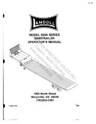
*CATTACH TO 12V DC (+)(SEE ELECTRICAL SCHEMATIC)16.25412,7STATIC LOADHOLDING BRAKE9.00228,66.12155,429.58751,3FLANGEDIA..5012,7 DIA.CABLE HOLE3.8196,8ATTACH TO GROUND (SEEELECTRICAL SCHEMATIC)5.05128,410.11256,89.12231,62.2156,1RAMSEY WINCH COTULSA OK3.7996,33.94100,0BARREL DIA..125-27NPT PORT(CONNECT 80 TO 150 PSI **PRESSURE LINE TO DISENGAGECLUTCH)4.62117,3AA5.53 12.25140,5311,21.7544,54.88124,0*DRUM9.75247,7PRESSURE IN GIVES COUNTER-CLOCKWISE DRUMROTATION VIEWED FROM MOTOR END.500-13UNC X .62" (15,7 MM) DEEPTAPPED HOLE (TYP. 4 PLACES EACHSIDE OF WINCH)4.56115,89.12231,6*2.2557,2(TYP.).500-13UNC X .75" (19,1 MM) DEEPTAPPED HOLE (TYP. 4 PLACES EACHEND BEARING)*1.1228,4WINCHPRESSURE IN GIVES CLOCKWISE DRUMROTATION VIEWED FROM MOTOR ENDVIEWA-AMOTOR CONTROL VALVE DETAIL.8822,4.875-14 SAE STRAIGHT THREADO-RING PORT (TYP. 2 PLACES)*NOTE: THESE HOLE LOCATIONS MUST BE HELD WITHIN ±.03" (0,8 MM) OFTRUE POSITION. RECOMMENDED MOUNTING HOLE DIAMETER IS .53" (13,5 MM).** CAUTION: PRESSURE MUST NOT EXCEED 150 PSI.ATTACH TO GROUND (16 GA.WIRE SUPPLIED BY CUSTOMER)BUTTCONNECTORWITH AIR CYLINDER CLUTCH SHIFTERMODEL RPH-12,000ATTACH TO PTO INDICATOR SWITCH TORECEIVE 12V DC WHEN PTO IS ENGAGED.SWITCHNOTE: LIGHT SHOULD BE "ON" WHEN CLUTCH ISENGAGED AND "OFF" WHEN CLUTCH IS DISENGAGED.(TYP.)*1.1228,4(TYP.)(TYP.)INDICATOR LIGHT(ON WHEN CLUTCHIS ENGAGED)ELECTRICALSCHEMATIC12V BATTERY+_C2.2156,1*.5614,2NEHGAUTGELD*TLIENWHDIMENSIONS SHOWN ARE INCHES OVER MILLIMETERSWINCH MOUNTING CAPSCREWS MUST MEET OR EXCEED SAE GRADE 5 SPECIFICATION14
NOTES15
PARTS LIST RPH 12,000 WITH MANUAL CLUTCH SHIFTERITEM QTY. PART NO. DESCRIPTION1 1 234171 DRUM ASS'Y.2 1 276052 SHIFTER ASS'Y.-MANUAL3 1 306042 PISTON-BRAKE4 1 338300 END BEARING-MOTOR5 1 338301 END BEARING-GEAR HOUSING6 1 338302 HOUSING-BRAKE7 4 346045 PIN-BRAKE8 1 357504 SHAFT-INPUT/SUN GEAR9 2 395172 TIE PLATE10 1 402120 BEARING-GEAR HSG.11 1 402121 BEARING-MTR. END BEARING12 1 412084 BUSHING-DRUM (MTR. END)13 1 412085 BUSHING-DRUM (G.HSG. END)14 6 414303 CAPSCREW-3/8-16NC X 2-1/2 LG. HX.HD., GR. 5 PLTD.15 2 414948 CAPSCREW 1/2-13NC X 1-1/4 LG. SOC.HD.16 8 414581 CAPSCREW 1/2-13NC X 3/4 LG. HX.HD. GR.5 PLTD.17 2 414854 CAPSCREW 1/4-20NC X 1/2 LG. RD.HD. SLOT PLTD.18 4 414159 CAPSCREW 5/16-18NC X 1-1/2 LG. HX HD. GR5 Z/P19 1 414926 SETSCREW-3/8-16NC X 1 LG., SOCKET, NYLON20 1 416016 SETSCREW-1/4-20NC X 1/4 LG., HX. SOC. HD.21 1 418036 NUT 3/8-16NC HEX. JAM22 2 418218 LOCKWASHER-1/2 ID MED. SECT.23 1 431015 COUPLING-MOTOR24 2 432018 FITTING-7/16 ELBOW25 NOT USED26 4 438022 DISC-BRAKE27 1 442220 GASKET-BRAKE28 1 442223 GASKET-MOTOR29 1 444085 GEAR-RING30 1 456038 FITTING-VENT31 1 458090 MOTOR-HYDRAULIC32 1 462046 O-RING (DRUM)33 1 462056 O-RING34 1 462057 O-RING35 1 462058 O-RING36 1 462059 O-RING BACKUP37 1 462060 O-RING BACKUP38 1 472052 PLUG39 5 474111 PLATE-SEPARATOR40 1 486080 SEAL-GEAR HSG.41 1 490037 SNAP RING42 6 494110 SPRING-BRAKE43 4 494112 SPRING44 1 509009 TUBE ASSEMBLY45 1 516013 VALVE-MOTOR CONTROL46 1 518037 THRUST WASHER47 1 518047 THRUST WASHER48 1 518052 THRUST WASHER49 4 418163 LOCKWASHER – 5/16 MED SECT Z/P17
PARTS LIST RPH 12,000 WITH AIR-CYLINDER CLUTCH SHIFTERITEM QTY. PART NO. DESCRIPTION1 1 234171 DRUM ASS'Y.2 1 236020 LIGHT ASSEMBLY3 1 276053 SHIFTER ASS'Y.-AIR CYLINDER4 1 306042 PISTON-BRAKE5 1 312529 BRACKET-LIGHT6 1 338300 END BEARING-MOTOR7 1 338301 END BEARING-GEAR HOUSING8 1 338302 HOUSING-BRAKE9 4 346045 PIN-BRAKE10 1 357504 SHAFT-INPUT/SUN GEAR11 2 395172 TIE PLATE12 1 402120 BEARING-GEAR HSG.13 1 402121 BEARING-MTR. END BEARING14 1 412084 BUSHING-DRUM (MTR. END)15 1 412085 BUSHING-DRUM (G.HSG. END)16 2 414036 CAPSCREW 1/4-20NC X 1/2 LG.17 6 414303 CAPSCREW 3/8-16NC X 2-1/2 LG. HX.HD., GR. 5 PLTD.18 2 414948 CAPSCREW 1/2-13NC X 1-1/4 LG. SOC.HD.19 8 414581 CAPSCREW 1/2-13NC X 3/4 LG. HX.HD. GR.5 PLTD.20 4 414159 CAPSCREW 5/16-18NC X 1-1/2 LG. HX. HD. GR 5 Z/P21 1 414926 SETSCREW-3/8-16NC X 1 LG., SOCKET, NYLON22 1 416016 SETSCREW-1/4-20NC X 1/4 LG., HX. SOC. HD.23 1 418036 NUT 3/8-16NC HEX. JAM24 2 418218 LOCKWASHER-1/2 ID MED. SECT.25 1 431015 COUPLING-MOTOR26 2 432018 FITTING-7/16 ELBOW27 NOT USED28 4 438022 DISC-BRAKE29 1 442220 GASKET-BRAKE30 1 442223 GASKET-MOTOR31 1 444085 GEAR-RING32 1 456038 FITTING-VENT33 1 458090 MOTOR-HYDRAULIC34 1 462046 O-RING (DRUM)35 1 462056 O-RING36 1 462057 O-RING37 1 462058 O-RING38 1 462059 O-RING BACKUP39 1 462060 O-RING BACKUP40 5 474111 PLATE-SEPARATOR41 1 482013 BOOT42 1 482045 BOOT43 1 486080 SEAL-GEAR HSG.44 2 488007 SHIM45 1 490037 SNAP RING46 6 494110 SPRING-BRAKE47 4 494112 SPRING48 1 504021 SWITCH49 1 509009 TUBE ASSEMBLY50 1 516013 VALVE-MOTOR CONTROL51 1 518047 THRUST WASHER52 1 518052 THRUST WASHER53 4 418163 LOCKWASHER – 5/16 MED SECT Z/P19
PARTS LIST RPH 12,000 WITH BLOCKED CLUTCHITEM QTY. PART NO. DESCRIPTION1 1 234171 DRUM ASS'Y.2 1 306042 PISTON-BRAKE3 1 338300 END BEARING-MOTOR4 1 338301 END BEARING-GEAR HOUSING5 1 338302 HOUSING-BRAKE6 4 346045 PIN-BRAKE7 1 357504 SHAFT-INPUT/SUN GEAR8 2 395172 TIE PLATE9 1 402120 BEARING-GEAR HSG.10 1 402121 BEARING-MTR. END BEARING11 1 412084 BUSHING-DRUM (MTR. END)12 1 412085 BUSHING-DRUM (G.HSG. END)13 6 414303 CAPSCREW-3/8-16NC X 2-1/2 LG. HX.HD., GR. 5 PLTD.14 2 414948 CAPSCREW 1/2-13NC X 1-1/4 LG. SOC.HD.15 8 414581 CAPSCREW 1/2-13NC X 3/4 LG. HX.HD. GR.5 PLTD.16 2 414854 CAPSCREW 1/4-20NC X 1/2 RD.HD. SLOT PLTD.17 4 414159 CAPSCREW 5/16-18NC X 1-1/2 LG. HX. HD. GR 5 Z/P18 1 414926 SETSCREW-3/8-16NC X 1 LG., SOCKET, NYLON19 1 416016 SETSCREW-1/4-20NC X 1/4 LG., HX. SOC. HD.20 1 416030 SETSCREW 5/8-18NF X 1 LG. HX.SOC.HD.21 1 418036 NUT 3/8-16NC HEX. JAM22 1 418088 NUT 5/8-18NF23 2 418218 LOCKWASHER-1/2 ID MED. SECT.24 1 426048 PLUNGER25 1 431015 COUPLING-MOTOR26 2 432018 FITTING-7/16 ELBOW27 NOT USED28 4 438022 DISC-BRAKE29 1 442220 GASKET-BRAKE30 1 442223 GASKET-MOTOR31 1 444085 GEAR-RING32 1 456038 FITTING-VENT33 1 458090 MOTOR-HYDRAULIC34 1 462046 O-RING (DRUM)35 1 462056 O-RING36 1 462057 O-RING37 1 462058 O-RING38 1 462059 O-RING BACKUP39 1 462060 O-RING BACKUP40 1 472052 PLUG41 5 474111 PLATE-SEPARATOR42 1 486080 SEAL-GEAR HSG.43 1 490037 SNAP RING44 6 494110 SPRING-BRAKE45 4 494112 SPRING46 1 509009 TUBE ASSEMBLY47 1 516013 VALVE-MOTOR CONTROL48 1 518037 THRUST WASHER49 1 518047 THRUST WASHER50 1 518052 THRUST WASHER51 4 418163 LOCKWASHER – 5/16 MED SECT Z/P21
LIMITED WARRANTYRAMSEY WINCH warrants each new RAMSEY <strong>Winch</strong> to be free from defects in material and workmanshipfor a period of one (1) year from date of purchase.The obligation under this warranty, statutory or otherwise, is limited to the replacement or repair at theManufacturer's factory, or at a point designated by the Manufacturer, of such part that shall appear to theManufacturer, upon inspection of such part, to have been defective in material or workmanship.This warranty does not obligate RAMSEY WINCH to bear the cost of labor or transportation charges inconnection with the replacement or repair of defective parts, nor shall it apply to a product upon whichrepair or alterations have been made, unless authorized by Manufacturer, or for equipment misused,neglected or which has not been installed correctly.RAMSEY WINCH shall in no event be liable for special or consequential damages. RAMSEY WINCHmakes no warranty in respect to accessories such as being subject to the warranties of their respectivemanufacturers.RAMSEY WINCH, whose policy is one of continuous improvement, reserves the right to improve itsproducts through changes in design or materials as it may deem desirable without being obligated toincorporate such changes in products of prior manufacture.If field service at the request of the Buyer is rendered and the fault is found not to be with RAMSEYWINCH's product, the Buyer shall pay the time and expense to the field representative. Bills for service,labor or other expenses that have been incurred by the Buyer without approval or authorization byRAMSEY WINCH will not be acceptedSee warranty card for details.RAMSEY WINCH COMPANYPost Office Box 581510 Tulsa, Oklahoma 74158-1510Telephone: (918) 438-2760 FAX: (918) 438-6688OM914002-0802-F