10 APOLLO - DRYER BOOSTER FANS.cdr - Reversomatic
10 APOLLO - DRYER BOOSTER FANS.cdr - Reversomatic
10 APOLLO - DRYER BOOSTER FANS.cdr - Reversomatic

Create successful ePaper yourself
Turn your PDF publications into a flip-book with our unique Google optimized e-Paper software.
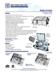
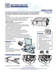
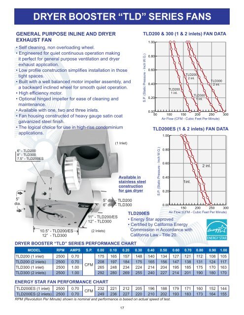
<strong>DRYER</strong> <strong>BOOSTER</strong> “TLD” SERIES <strong>FANS</strong>GENERAL PURPOSE INLINE AND <strong>DRYER</strong>EXHAUST FAN• Self cleaning, non overloading wheel.• Engineered for quiet continuous operation makingit perfect for general purpose ventilation and dryerexhaust application.• Low profile construction simplifies installation in thosetight spaces.• Built with a well balanced motor impeller assembly, anda backward inclined wheel for smooth quiet operation.• High efficiency motor.• Optional hinged impeller for ease of cleaning andmaintenance.• Available with one, two and three inlets.• Fan housing constructed of heavy gauge satin coatgalvanized steel finish.• The logical choice for use in high-rise condominiumapplications.TLD200 & 300 (1 & 2 inlets) FAN DATAS.P. (Static Pressure - Inch W.G.)1.000.800.600.400.20TLD200ES (1 & 2 inlets) FAN DATA1.00TLD2001 inl.TLD2002 inl.TLD3001 inl.TLD3002 inl.0.0050 <strong>10</strong>0 150 200 250Air Flow (CFM - Cubic Feet Per Minute)3006” - TLD2008” - TLD3007.5” - TLD200ES5”dia.H<strong>10</strong>.5” - TLD200/ES12” - TLD3005” dia. - TLD2006” dia. - TLD30011” - TLD200/ES12” - TLD300(2 Inlets)(1 Inlet)Available instainless steelconstructionfor gas dryer<strong>DRYER</strong> <strong>BOOSTER</strong> “TLD” SERIES PERFORMANCE CHARTMODELTLD200 (1 inlet)TLD200 (2 inlets)TLD300 (1 inlet)TLD300 (2 inlets)RPM2500250025002500AMPS0.700.701.001.00S.P.CFM0.001752082652920.<strong>10</strong>1651972482800.20157184234269S.P. (Static Pressure - Inch W.G.)0.800.600.400.201inl.TLD200ES• Energy Star approved• Certified by California EnergyCommission in Accordance withCalifornia Law - Title 20.0.301481752242550.401401652142402 inl.0.00150 200 250 300Air Flow (CFM - Cubic Feet Per Minute)0.501341562042270.60 0.70 0.801271471952141211381852011121311751900.90<strong>10</strong>81241701801.00<strong>10</strong>5117163170ENERGY STAR FAN PERFORMANCE CHARTTLD200ES (1 inlet) 2500 0.70CFM 232 221 212 205 196 188TLD200ES (2 inlets) 2500 0.70 249 236 227 220 2<strong>10</strong> 202RPM (Revolution Per Minute) shown is nominal and performance is based on actual speed of test.17919317118316017315216414415517
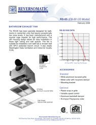
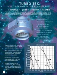
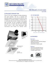
<strong>DRYER</strong> <strong>BOOSTER</strong> “RI” SERIES <strong>FANS</strong>9.5”dia.A O.D.PERFORMANCE CHARTMODELRI-150RI-200RI-250CUBIC FEET PER MINUTE AT STATIC PRESSURE0.00 0.<strong>10</strong> 0.20 0.30 0.40 0.50 0.60 0.70 0.80 0.90 1.00156 148 140 132 125 112 <strong>10</strong>1 94 88 -2142528”198227A O.D.RI150 - 3 7/8 ”RI200 - 4 7/8 ”RI250 - 5 7/8 ”A O.D.186208• Engineered to provide effective andreliable operation.• Fan housing constructed of heavygauge satin coat steel with bakedenamel finish.• Meet Washington State Ventilationand Indoor Air Quality Code.FAN MOTORRPM (Revolution Per Minute) shown is nominal and performance is based on actual speed of test.Unit was tested with inlet cone, backdraft damper and outlet duct.173194MODELAMPSWattsRPM159180RI-150 RI-200 RI-250<strong>DRYER</strong> <strong>BOOSTER</strong> “PWS” SERIES <strong>FANS</strong>0.70852500146165133150ACCESSORIESStandard:- Mounting brackets for wall or trussmounting (fig.1)Optional:- Mounting clamps for use with rigidduct, complete with foam rubberinsulation (fig.2)- Suspension bracket (fig.3)- Backdraft damper with butterflyvalve to prevent cold air fromentering when fan is not in use (fig.4)121133fig.1 fig.2 fig.3 fig.4<strong>10</strong>912097<strong>10</strong>8--93CAThe PWS series is specially designed to exhaust air from the dryer. It hasbeen equipped with a paddle wheel impeller to prevent lint buildup.MinimumClearanceH17/8”Ddia.FEBPERFORMANCE CHARTMODELOutletTransitionModelPWS<strong>10</strong>0/200PWS300DIMENSIONS:MODELPWS<strong>10</strong>0PWS200PWS300RPMAa”Aa”3 3/44 1/2dia.PWS<strong>10</strong>0 - 5”PWS200 - 6”PWS300 - 7”A91/4”91/4”11”B11”11”123/4”Bb”Bb”3 1/44 1/25"C4 ½”4 ½”5 ½”AMPSACCESSORIESStandard:• Mounting bracketsOptional:• Lint trap• Outlet TransitionD5”6”7”S.P.E33/4”33/4”41/2”F31/4”31/4”41/4”0.00H81/2”91/2”11”0.<strong>10</strong>PWS<strong>10</strong>0, 200 & 300 FAN DATAS.P. (Static Pressure - Inch W.G.)0.200.600.500.400.300.200.<strong>10</strong>0.000.30PWS<strong>10</strong>0<strong>10</strong>0 200 300Air Flow (CFM - Cubic Feet Per Minute)0.40PWS2000.50PWS3000.60SIDE VIEWPWS<strong>10</strong>0PWS200PWS3001550155015501.22.33.3CFM18920530017418528415817126714015525012013523198<strong>10</strong>8206749317718
<strong>DRYER</strong> <strong>BOOSTER</strong> <strong>FANS</strong> EQUIPPED w/ PRESSURE SENSOR5” diaT L DWall Box17 3/4”20 3/4”11”6”Lint TrapTLD RI PWS“TLD” SERIESInsulationTLD fans feature a low profile, very high performance, high staticpressure, self cleaning backward inclined impeller and high efficiencymotor making it ideal to exhaust dryer where a long run of duct isnecessary.5’4”R I“RI” SERIESRI fans have equally high performance as the TLD series. Theseinline round booster fans are constructed of heavy gauge steel andare powder coated to resist corrosion.9.5”dia. A O.D.A O.D.NOTE: All fans equipped with Pressure Sensormust be installed with sensor mounted verticallyor horizontally. NEVER FACE SENSOR DOWN.A8”CA O.D.RI150 - 3 7/8 ”RI200 - 4 7/8 ”RI250 - 5 7/8 ”“PWS” SERIESPWS fans are especially designed to exhaust dryers Hi-Risecondominiums and have an aluminum self cleaning paddle wheelimpeller for low maintenance. These fans are constructed of heavygauge satin coat steel to resist corrosion.PWSBDIMENSIONS:MODEL A B C DPWS<strong>10</strong>0PWS20091/4”91/4”11”11”4 ½” 11 ½”4 ½” 11 ½”PWS300 11” 123/4” 5 ½” 12 ½”D<strong>DRYER</strong> <strong>BOOSTER</strong> <strong>FANS</strong> w/ BUILT IN LINT TRAPTLDDWingNut8”2½”FAEBCRemovable See ThruPlexiglass Door c/wAttached Lint ScreenPWSD8”F3”EACBDIMENSIONS:MODELTLD200LTLD300LPWS<strong>10</strong>0LPWS200LPWS300LA13”14.5”6.5”6.5”7.5”B11”12”11”11”12.5”C6”8”9.5”9.5”11”D(dia.)NOTE:- Lint trap must be cleaned monthly or as required byremoving the two wing nuts and pulling the lint screendoor down by the handle.- Clean fan assembly as required by removing two wingnuts from the main plate and motor will swing open.- Make sure the motor is unplugged to ensure there is nopower to the motor.- Install fan combination lint trap where it is easilyaccessible for cleaning5”6”5”6”7”E<strong>10</strong>.5”12”4.5”4.5”5.5”F6”7”6”7”8”19
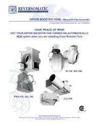
AUTOMATIC START FOR <strong>DRYER</strong> <strong>BOOSTER</strong> <strong>FANS</strong>DSC300 (Dryer Starter Control Box)Dryer Starter Control box DSC300 is a pre-wired unit with dryer plug for easyand simple installation for the electrician. This control works in conjunction withthe booster fan. When booster fan is in “ON” it will engage power to the startercontrol box and only then the dryer can be turned “ON”.NOTE:If booster fan for any reason does not work, the dryer can not be turned “ON”.DSC300DAS200 & DAS250 (AMP Sensor)The DAS200 device senses when a clothes dryer is drawing 1.2 Amp. ofcurrent. When this occurs a relay contact closes turning the dryer vent boosterfan “ON”. When current drops below the 2 Amp. threshold the relay contactsopen turning the booster fan “OFF”.DAS200DAS250The DAS250 device senses when a clothes dryer is drawing1.2 Amp. of currentand then closes the output switch to activate the dryer vent booster fan. Whenthe dryer cycle is complete and the current drops below the threshold, theoutput switch will remain closed for 5 minutes to allow heat to be removed fromthe vent before the switch is opened again.DHB<strong>10</strong>0 (Heat Sensor)Heat sensor unit is installed in the exhaust pipe of the dryer. During dryeroperation, heat is produced allowing the sensor to automatically engage thebooster fan.DHB<strong>10</strong>0PRESSURE SENSORPRESSURE SENSORWhen a laundry dryer is turned on it quickly produces dynamic air pressure build upin the duct system of which the dryer booster fan is connected to. When thepressure build up within the system is greater than the air pressure switch set point(0.02” - 0.05”) the pressure relay closes and the timer cycle is initiated which thancompletes the electrical circuit and the booster fan starts. The timer cycle relayperiod is 600 seconds closed and 60 seconds open. If the dryer is on it will continueto produce dynamic pressure in the system and the booster fan will continue to runfor additional timer cycles. Once the dryer is turned off it no longer producesdynamic air pressure in the system. When the air pressure within the duct system isless than the switch set point pressure the pressure relay will open. The booster fanwill continue to run until the completion of the 600 second closed timer cycle. Duringthe 60 second open timer cycle power is interrupted and the booster fan will slowlycome to a stop and remain off until the dryer is turned back on and the system cycleis once again initiated.* For more information visit www.reversomatic.com20