CHEVROLET Spark - Fortin Electronic Systems
CHEVROLET Spark - Fortin Electronic Systems
CHEVROLET Spark - Fortin Electronic Systems

You also want an ePaper? Increase the reach of your titles
YUMPU automatically turns print PDFs into web optimized ePapers that Google loves.
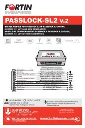
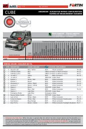
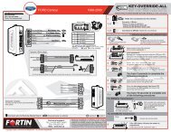
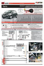
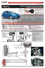
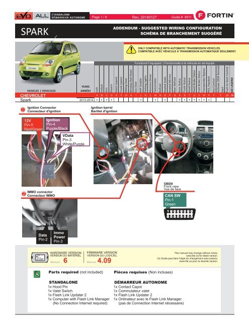
EVOINTERFACE MODULEHARDWARE VERSION : 3FIRMWARE VERSION : 4.0+Date: xx-xxPATENTS PENDING US: 2007-228827-A1Made in Canada www.fortinbypass.comService No : 000 102 04 2536STANDALONEDÉMARREUR AUTONOME Page 1 / 6 Rev. 20140127 Guide # 9911SPARKADDENDUM - SUGGESTED WIRING CONFIGURATIONSCHÉMA DE BRANCHEMENT SUGGÉRÉONLY COMPATIBLE WITH AUTOMATIC TRANSMISSION VEHICLES.COMPATIBLE AVEC VÉHICULE À TRANSMISSION AUTOMATIQUE SEULEMENT.<strong>CHEVROLET</strong><strong>Spark</strong>Ignition ConnectorConnecteur d'ignition2013-2014Ignition barrelBarillet d'ignition12VPin-5Red/GreenIgnitionPin-4Purple/BlackVDataPin-3White/PurpleIMMO connectorConnecteur IMMOOBDIIFront viewVue de faceCAN SWPin-1Green11 2 3 4 5 6 7 89 10 11 12 13 14 15 16DataPin-2ImmoPowerPin-3HARDWARE VERSIONVERSION DU MATÉRIELMinimumFIRMWARE VERSIONVERSION DU LOGICIEL6 Minimum 4.09This manual may change without notice.www.ifar.ca for latest version.Ce Guide peut faire l'objet de changement sans préavis.www.ifar.ca pour la récente version.Parts required (not included)STANDALONE1x Hood Pin1x Valet Switch1x Flash Link Updater 21x Computer with Flash Link Manager(No Connection Internet required)Pièces requises (Non incluses)DÉMARREUR AUTONOME1x Contact Capot1x Commutateur valet1x Flash Link Updater 21x Ordinateur avec le Flash Link Manager(pas de Connection Internet nécessaire)
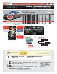
This Guide may change without notice. www.ifar.ca for latest version.Ce Guide peut faire l’objet de changement sans préavis. www.ifar.ca pour la récente version.KIAPARTSRIOREQUIRED- PUSH-TO-START(NOT INCLUDED) | PIÈCES REQUISES (NON INCLUSES)Page 32 / 46FLASH LINKUPDATER 2FLASH LINK MANAGERSOFTWARE | PROGRAMME1xHood Pin1xValet SwitchMicrosoft Windows Computer(No Internet connection required)Ordinateur Microsoft Windows(Pas de connection Internet requise)Optionnal | OptionnelKIA RIO - PUSH-TO-STARTEVO-ALL STAND ALONE CONFIGURATION | CONFIGURATION DU EVO-ALL EN DÉMARREUR AUTONOMEFLASH LINK MANAGERSOFTWARE | PROGRAMMEFLASH LINKUPDATER 2E O ALLConnect the EVO-ALL moduleto the Flash Link Updater 2.(Sold separately)Branchez le module EVO-ALLau Flash Link Updater 2.(Vendu séparément)Set the EVO-ALL asa remote starter withthe activation of thefunction 15 with theFlash LinkManager and SAVEOPTIONS.Réglez le EVO-ALLcomme un démarreurà distance avecl'activation de l'option15 avec le Flash LinkManager etENREGISTREZ LESOPTIONS.15 - OEM Remote Stand Alone Remote StarterRemote start the vehicle when the OEM remote's lock button is pressed3x times. An aftermarket remote car starter is NOT require.2nd start attemptDiesel mode3 minute runtime7 minute runtime15 minute runtime15 - Démarreur à Distance Autonome avec le Télécommande OEMDémarrage à distance lorsque le bouton verrouillage de la télécommanded'origine est appuyez 3x fois. PAS de démarreur à distance requis.2e essai de démarrageMode Diesel3 minutes runtime7 minutes runtime15 minutes runtimeSAVE OPTIONSENREGISTRER LES OPTIONSREMOTE STARTER FUNCTIONNALITY | FONCTIONNALITÉS DU DÉMARREUR À DISTANCE3X LOCKSTARTAll doors must be closed.Toutes les portes doivent être ferméesPress the OEM remote’s Lock button 3x toremote-start (or remote-stop) the vehicle.Appuyez sur le bouton Verrouillage 3X de latélécommande d'origine pour démarrer à distance(ou arrêter à distance) le véhicule.The vehicle will START.Le véhicule DÉMARRE.
This Guide may change without notice. www.ifar.ca for latest version.Ce Guide peut faire l’objet de changement sans préavis. www.ifar.ca pour la récente version.DESCRIPTION | DESCRIPTIONPage 3 / 46LED | DELBlue | BleuYellow | JauneRed | RougeNOT INCLUDEDNON INCLUS2 PIN CONNECTOR:TB CONTROL(WHITE | BLANC)ERed | RougeBlack | NoirBlue | BleuWhite | BlancB4 PIN CONNECTOR:DATA-LINK(BLACK | NOIR)12V Battery (+) | 12V Batterie (+)Ground (-) | Masse (-)DATADATAFoot Brake | Frein (pied) SignalTachometerTrunk Release | ValiseHand Brake | Frein à Main SignalHood Status | Capot StatutsSee configurationSee configurationSee configurationSee configurationSee configurationBlack | NoirPink | RoseYellow/Black | Jaune/NoirBrown/White | Brun/BlancPink/Black | Rose/NoirPurple/Yellow | Mauve/JauneGreen/White | Vert/BlancGreen/Red | Vert/RougeWhite/Black | Blanc/NoirLt. Blue | Bleu Pâle1112131415161718192012345678910A20 PIN CONNECTOR:MAIN HARNESS | HARNAIS PRINCIPAL(WHITE|BLANC)Yellow | JaunePurple | MauvePurple/White | Mauve/BlancGreen | VertWhite | BlancOrangeOrange/Black | Orange/NoirDk. Blue | Bleu foncéRed/Blue | Rouge/BleuLt. Blue/Black | Bleu Pâle/NoirSee configurationLock | VerrouilleUnlock | DéverrouilleDoor Status | Statuts PortesTrunk Status | Statuts ValiseAUX 1AUX 2GWR (Ground While Running)See configurationSee configuration543215 PIN CONNECTOR: CAN-BUS (WHITE | BLANC)Brown | BrunCAN 1 WIRE (SW)Gray/Black | Gris/NoirGray | GrisOrange/Brown | Orange/BrunOrange/Green | Orange/VertCAN 2 LOWCAN 2 HIGHCAN 1 LOWCAN 1 HIGHCCopyright © 2012,FORTIN AUTO RADIO INCTOUS DROITS RÉSERVÉS6543216 PIN CONNECTOR: RELAY | RELAIS (RED | ROUGE)White/Red | Blanc/RougeCOMM2White/Blue | Blanc/BleuNO2DWhite/Green | Blanc/VertNC2Yellow/Red | Jaune/RougeCOMM1Yellow/Blue | Jaune/BleuNO1Yellow/Green | Jaune/VertNC1KIAVEHICLESRIO - PUSH-TO-STARTEQUIPPED WITH AN OEM ALARM VÉHICULES ÉQUIPPÉS D'UNE ALARME D'ORIGINESome vehicles must be UNLOCKED to disarm the OEM alarmbefore remote start.Enable option #12 using the FlashLink Manager.When this option is enabled the module will automaticallyUNLOCK before remote start and LOCK after the vehicle hasremote started.Certains véhicules doivent être DÉVERROUILLÉS avant ledémarrage à distance pour désarmer l'alarme d'origine.Activez l'option#12 avec le FlashLink Manager.Lorsque cette option est activée, le module déverrouilleautomatiquement avant le démarrage à distance et reverrouilleaprès que le véhicule a démarré à distance.
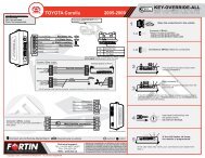
E O ALLALLHARDWARE VERSION : 3FIRMWARE VERSION : 4.0+Date: xx-xxEVOINTERFACE MODULEPATENTS PENDING US: 2007-228827-A1Made in Canada www.fortinbypass.comService No : 000 102 04 2536®This Guide This may Guide change may change without without notice. www.ifar.ca notice. www.ifar.ca for latest for version. latest version.Ce Guide Ce peut Guide faire peut l’objet faire de l'objet changement de changement sans préavis. sans préavis. www.ifar.ca www.ifar.ca pour la récente pour la récente version. version. Page 34 / 546KIA WIRING RIO - CONNECTION PUSH-TO-START| GUIDE | GUIDE BRANCHEMENTSDE SPARKEVO-ALL STAND ALONEAutomatic transmission ONLY | Transmission Automatique SEULEMENTWARNING: Once the vehicle is remote started the OEM remote will no longer function and will not be able to shut down the engine or unlock the vehicle. Optional RF Kit recommended.AVERTISSEMENT: Lorsque le véhicule est démarré à distance, la télécommande d'origine ne sera plus fonctionnelle et ne sera plus en mesure d'éteindre le moteur ou de déverrouillerle véhicule. Kit RF optionnel recommandé.Hood PinOptionalOptionnelOptionalOptionnelWITH | AVEC DATA-LINK:RF-KIT ORREMOTE STARTERKIT REF OUDÉMARREUR ÀDISTANCEWITH | AVEC DATA-LINK:DIRECT CONNECTIONBRANCHEMENT DIRECTERS2 INRS112V BATTERY (+)Ground | Masse (-)GroundValet SwWITHOUT | SANS DATA-LINK:Cut | CoupezCut | CoupezB4B3Red B4Black B3Blue B2White B1RedBlack12V BATTERYGroundGround(+) IgnitionYellow IN(-) LockPurple IN(-) UnlockPurple/White INGreen OUTWhite OUTOrange INOrange/Black INHood PinDk. Blue INRed/Blue IN(-) LOCK/UNLOCK INPUT EXTERNAL CONTROLCONTRÔLE DE (-) VERROUILLAGE/DEVÉRROUILLAGE(ENTRÉE) EXTERNESTART / STOP EXTERNAL CONTROLCONTRÔLE DE DÉMARRAGE/ARRÊT EXTERNE(-) External Input(-) Parking Light OUTTO VEHICLE PARKING LIGHT SEE WIRECOLOR.COMAUX LUMIÈRES DE STATIONNEMENT DU VÉHICULE.VOIR WIRECOLOR.COMLt. Blue/BlackBlackPinkYellow/BlackBrown/WhitePink/BlackPurple/YellowGreen/WhiteGreen/RedWhite/BlackLt. BlueOUTOUTINOUTOUTINA1A2A3A4A5A6A7A8A9A10A11A12A13A14A15A16A17A18A19A20BACDC5C4C3C2C1D6D5D4D3D2D1HARDWARE VERSIONVERSION DU MATÉRIELMinimumBrownGray/BlackGrayOrange/BrownOrange/GreenWhite/RedWhite/BlueWhite/GreenYellow/RedYellow/BlueYellow/Green6FIRMWARE VERSIONVERSION DU LOGICIEL4.09 OROU 70. 03MinimumGM MinimumCAN SWCOMM1NC1COMM2NO2[ ]D2D3D4A10D6A18B4A1DataPin-2Immo PowerPin-312VPin-5Red/GreenRouge/VertIgnition Pin-4 Purple/BlackVDataPin-3White/PurpleBlanc/Mauve1C5CAN SWPin-1GreenVert1 2 3 4 5 6 7 8Ground9 10 11 12 13 14 15 16Key BypassIMMO connectorBack viewConnectorBurgundyContournementde clé Vue de DosConnecteur IMMObourgogneBack viewIgnitionConnectorVue de DosConnecteurd'ignitionOBDIIFront viewVue de face
ACC ONPUSHACC ONPUSHACC ONPUSHACC ONACC ONPUSHThis Guide may change without notice. www.ifar.ca for latest version.Ce Guide peut faire l’objet de changement sans préavis. www.ifar.ca pour la récente version.PROGRAMMING PROCEDURE | PROCÉDURE DE PROGRAMMATION 2/2|1 2Page 35 / 46If the LED is not solidYELLOW disconnectthe 4 Pin connector(Data-Link) and goback to step 1.EVO-ALLEVO-ALLEVO-ALLPress and holdthe programmingbutton.Appuyez etmaintenirenfoncé le boutonde programmation.Insert the 4 Pin(Data-Link)connector.Insérez leconnecteur 4 pins(Data-Link).The LED willalternate betweenBLUE, YELLOWand RED flashes.Les DELSalternent entre unflash BLEU,JAUNE etROUGE.Release theprogramming buttonwhen the LED isYELLOW.Relâchez le boutonde programmationquand la DEL estJAUNE.Si le DEL n'est pasJAUNE débranchez leconnecteur 4 pins(Data-Link) et allez audébut de l'étape 1.EVO-ALLInsert the remainingrequired connectors:20 pin (White), 5 pin (White),6 pin (Red). 2 pin (White),Insérez lesconnecteurs requisrestants:20 pins (Blanc), 2 pins (Blanc),5 pins (Blanc), 6 pins (Rouge)3Press and releasethe programmingbutton once.Appuyez etrelâchez le boutonde programmation1 fois.The YELLOW LEDflashes once (1x)every second.La DEL JAUNEclignote une (1x) foisà toutes lessecondes.Wait for theYELLOW and theRED LED to turnON.Attendre que laDEL JAUNE etROUGE s'allume.CAUTIONThe next step must be completed in less than5 seconds.If the delay is not respected, disconnect allconnectors and go back to step 1.ATTENTIONla prochaine étape doit être complétée en moinsde5 secondes.Si le délai n'est pas respecté, débranchez tousles connecteurs et allez au début de l'étape 1.4 5 sec. maxLOCKSTARTIGNLOCKOFFSTARTLOCKSTARTLOCKSTARTIGNx10Turn the Ignition tothe ON/RUNposition.Tournez la clef enposition ignition(ON).Wait until the REDLED flashes once(1x) and then turnsback ON.Attendre que laDEL ROUGE flashune (1x) fois et serallume.Turn the IgnitionOFF.Tournez la clef àOFF.Remove the keyfrom the ignitionswitch.Retirez la clef del'ignition.Reinsert the keyand turn theIgnition to theON/RUN position.Réinsérez la clef etTournez la clef enposition ignition.The YELLOW LEDwill flash rapidly ten(10x) times. Keybypass programmed.La DEL JAUNEclignotera dix (10x)fois rapidement.Contournement declé programmé.OFFLOCKSTARTThe YELLOW LEDwill turn back ON.The Blue LED willflash rapidly. CANdata programmed.La DEL JAUNE serallume.La DEL BLEUclignoterarapidement : RéseauCAN programmé.Turn the IgnitionOFF.Tournez la clef àOFF.All LED's turn OFF.Toutes les DELSs'éteignent.The module isnowprogrammed.Le module estprogrammé.
Page 6 / 6EVO-ALLHARDWARE VERSIONFIRMWARE VERSIONDate: xx-xxINTERFACE MODULEPATENTS PENDING US: 2007-228827-A1Made in Canada www.fortinbypass.comService No : 000 102 04 2536Module label | Étiquette sur le moduleNotice: Updated Firmware and Installation GuidesUpdated fi rmware and installation guides are posted on our web site on a regularbasis. We recommend that you update this module to the latest fi rmware anddownload the latest installation guide(s) prior to the installation of this product.Notice: Mise à jour microprogramme et Guides d’installationsDes mises à jour du Firmware (microprogramme) et des guides d’installationsont mis en ligne régulièrement. Vérifi ez que vous avez bien la dernière versionlogiciel et le dernier guide d’installation avant l’installation de ce produit.WARNINGThe information on this sheet is provided on an (as is) basis with no representation or warranty of accuracy whatsoever.It is the sole responsibility of the installer to check and verify any circuit before connecting to it. Only a computer safelogic probe or digital multimeter should be used. FORTIN ELECTRONIC SYSTEMS assumes absolutely no liability orresponsibility whatsoever pertaining to the accuracy or currency of the information supplied. The installation in every caseis the sole responsibility of the installer performing the work and FORTIN ELECTRONIC SYSTEMS assumes no liabilityor responsibility whatsoever resulting from any type of installation, whether performed properly, improperly or any otherway. Neither the manufacturer or distributor of this module is responsible of damages of any kind indirectly or directlycaused by this module, except for the replacement of this module in case of manufacturing defects. This module must beinstalled by qualified technician. The information supplied is a guide only. This instruction guide may change withoutnotice. Visit www.fortinbypass.com to get the latest version.MISE EN GARDEL’information de ce guide est fournie sur la base de représentation (telle quelle) sans aucune garantie de précision etd’exactitude. Il est de la seule responsabilité de l’installateur de vérifier tous les fils et circuits avant d’effectuer les connexions.Seuls une sonde logique ou un multimètre digital doivent être utilisés. FORTIN SYSTÈMES ÉLECTRONIQUES n’assumeaucune responsabilité de l’exactitude de l’information fournie. L’installation (dans chaque cas) est la responsabilité del’installateur effectuant le travail. FORTIN SYSTÈMES ÉLECTRONIQUES n’assume aucune responsabilité suite àl’installation, que celle-ci soit bonne, mauvaise ou de n’importe autre type. Ni le manufacturier, ni le distributeur ne seconsidèrent responsables des dommages causés ou ayant pu être causés, indirectement ou directement, par ce module,excepté le remplacement de ce module en cas de défectuosité de fabrication. Ce module doit être installé par un technicienqualifié. L’information fournie dans ce guide est une suggestion. Ce guide d’instruction peut faire l’objet de changementsans préavis. Consultez le www.fortinbypass.com pour voir la plus récente version.Copyright © 2006-2012, FORTIN AUTO RADIO INC ALL RIGHTS RESERVED PATENT PENDINGTECH SUPPORTTél: 514-255-HELP (4357)1-877-336-7797ADDENDUM GUIDEwww.fortinbypass.comWEB UPDATE | MISE À JOUR INTERNET