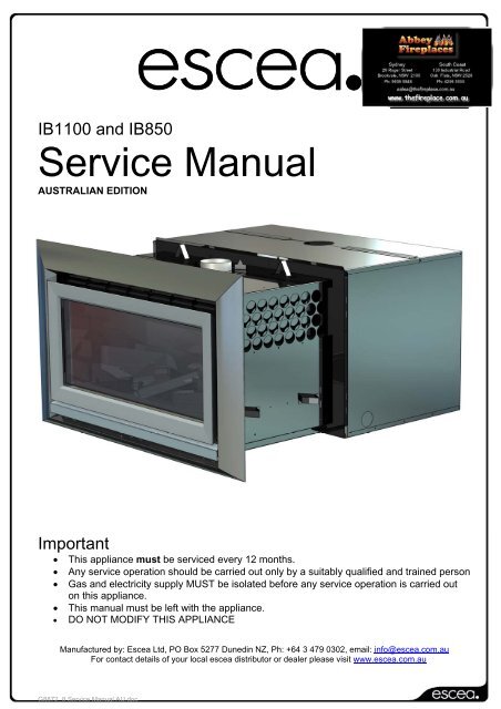
Escea 1100 & 850 Service Manual.pdf
Escea 1100 & 850 Service Manual.pdf
Escea 1100 & 850 Service Manual.pdf

You also want an ePaper? Increase the reach of your titles
YUMPU automatically turns print PDFs into web optimized ePapers that Google loves.
Draught DiverterBimetallic TripIn the unlikely event that the fans have stalled, and the snap disk on thelid of the fire has tripped, this would show an E3 also. Simply check thatthe fans are running normally after resetting and running the fire again.Note: This error has a permanent lock out and will require the unit to be reset 10 minutesafter the initial error (turning the power to the fire off "at the wall" then on again after afew seconds).4Valve SolenoidCheck FailureThe valve solenoids have failed the pre-ignition test. This is to detect afaulty valve solenoid. However, it is possible that some of the wiringconnections between the resistors and the solenoids are not secure, or awire has dislodged. Check that the connections to each solenoid andresistor are secure and in place. It may be that the connections on theends of the wires need to be tightened a little (eg with a pair of pliers) toensure a robust connection to the valve or resistor terminal.It could also be that one of the solenoids on the valve inside the fire havefailed. If this is the case the valve will need to be replaced.Remote cannotcommunicate withfireThe remote cannot communicate with the fire. Reasons for this couldinclude the fire being off "at the wall" i.e. a loss of power to the fire or theremote is outside of its effective radio frequency range (too far away fromthe fire). Typical remote range is 1m to 12m. Ensure there is power to thefire by pressing the auxiliary on/off (red) button on the fire, then press theon/off button on the remote to clear the error.Valve Temp SensorTripThe valve temperature sensor has detected abnormally high temperaturesaround the valves. This is an unlikely fault and should it occur pleasecontact the <strong>Escea</strong> agent you purchased the fire from.Note: This error has a permanent lock out and will require the unit to be reset 10 minutesafter the initial error (turning the power to the fire off "at the wall" then on again after afew seconds).Temp Sensor ErrorThis indicates a fault with one of the two temperature sensors installed inyour fire. Resetting the fire (turning the power to the fire off then on againafter a few seconds) and if the fault reappears, please contact your <strong>Escea</strong>sales agent to organise a replacement sensor. These sensors must notbe disabled or bypassed.Note: This error has a permanent lock out and will require the unit to be reset 10 minutesafter the initial error (turning the power to the fire off "at the wall" then on again after afew seconds).G8872_8 <strong>Service</strong> <strong>Manual</strong> AU.doc
Cleaning the Fascia, Log Set and Glass:5NEVER RUB THE FASCIA. The outside of the fascias must only be cleaned with a cleandamp cloth, dry off after cleaning. The high temp silver powder coating that is used on<strong>Escea</strong> fascia parts contains certain amounts of aluminium that when rubbed too hard willoxidise leaving a black smudge that cannot be removed. Always clean when cold.This is a service procedure that will need to be carried out when ever soot builds up on logsand/or inside of glass.If soot build up becomes excessive or regular then one of the following actions may be required;• Reset gas pressure, pressure may be too high;• Reposition log set so that front edge of each log is just behind each row of holes in burnertop;• Clear any blockage from primary air port of burner;• Check to make sure flue system is drawing wellor that there are no adverse environmentalconditions inhibiting clean combustion.Step 1:Lift off the inner fascia by removingthe screws attaching the bottom ofthe fascia to the firebox and liftingit up and off.Step 2:Unscrew the top glassretainer and remove it. Takecare that the glass doesnot fall forwards at thisstage.Step 3:Lift out glass and place it carefullyaside.Step 4:Clean the inside and outside of glass withnormal glass cleaning products. Use aCLEAN DRY cloth to remove cleanerresidue. Stubborn marks may be cleanedwith a ceramic glass cleaner.Step 5:Take out log set and gently brush anysoot from log with a soft hearth brush.The burner tops can be vacuumed toremove any excess material.Step 6:Replace in opposite order and test run heater.G8872_8 <strong>Service</strong> <strong>Manual</strong> AU.doc
Checking Operating Pressure:This is done at the regulator located at the front RH corner of the appliance.This is best done before the fascia panels have been fitted to avoid fascia damage. A pressuretest point is available for the operating test pressure only (as shown below).61) Check the inlet pressure to the appliance. Attach manometer tube to the first test pointupstream of the appliance (typically at the gas utility meter or auto change device for apropane bottle station)2) Run the heater on full (all three burners for IB<strong>850</strong> and two burners for IB<strong>1100</strong> arerunning) and measure inlet pressure. If pressure does not fall within the maximum orminimum pressures listed on the table below then reassess installation pipe size orupstream regulator settings.3) Remove the operating pressure test point screw. Connect manometer tube andmeasure pressure with heater running on full (all three burners for IB<strong>850</strong> and twoburners for IB<strong>1100</strong> are running).4) The heater regulator pressure has been factory set to 0.87kPa for Natural Gas heatersand 2.30Kpa for LPG (PROPANE) heaters. Please check that the operating pressureis exactly as listed and if not, adjust screw in centre of regulator until pressure iscorrect.5) Replace operating test point screw and leak test both test points.ABCA = Operating Pressure test pointB = Pressure adjustment screwC = Inlet gas connectionIB<strong>850</strong> and IB<strong>1100</strong> Pressure TableGas TypePROPANENatural GasMinimum Inlet Pressure 2.5kPa 1.2kPaMaximum Inlet Pressure 5.0kPa 5.0kPaOperating Pressure 2.30kPa 0.87kPaG8872_8 <strong>Service</strong> <strong>Manual</strong> AU.doc
Replacing Electronic Drawer8ISOLATE THE POWER TO THE FIRE BEFORE PROCEDURE.All of the electronic components of the heater have been located on a removable drawer.This drawer is located on the left hand outer side of the IB<strong>850</strong> and IB<strong>1100</strong>. On the back of thedrawer are two large connectors that unplug as the drawer is removed so only the three wiresconnecting the electronics to the ignition and flame rods must be removed manually from thePCB (Printed Circuit Board).Step one: Remove outer fascia by taking out two screws located behind the bottom fascia trimpanel.Step Two:Take out the two screws at each end of theelectronic drawer and pull drawer directlyoutwards.Step Three:Carefully remove the two wires shownfrom the white ignition module.Wire Entry:IB<strong>850</strong>& IB<strong>1100</strong>1. Flame Rod2. Spark LeadNote: It is important that theflame rod & spark lead wires sitin this position in the electronic tray.G8872_8 <strong>Service</strong> <strong>Manual</strong> AU.doc
ONLYSET TIMEFANBOOSTReplacing a Wireless Control:If the wireless control becomes lost or damaged, a new one can be ordered from any <strong>Escea</strong>retail agent.When you have the new remote, the following procedure needs to be followed to “teach” theremote to only communicate with that fire.91. Ensure the fire and remote are set to “Off” (only the time is displayed on the remote).2. Press the – (minus), + (plus) and the Fan Boost buttons simultaneouslyuntil all the characters on the display light up. This will put the remote intotest mode and the two large temperature digits should be reading 00.FLAMEEFFECTCSET3. Press and hold the – (minus) button until the two large temperature digitsreading 00 start to flash slowly. Release the – (minus) button. The remotecontrol is now ready to be addressed to the fire.TIMER SELECTACTIVATE TIMER4. Press and hold the red auxiliary on/off button onthe fireplace for a minimum of eight seconds, or untilthe two large temperature digits start countingupwards from 00 to 99 repeatedly.Note: Pressing the red auxiliary button on/off button will start the fire. Once the remote control iscounting the fire can be turned off by pressing the red auxiliary button again.5. Press the large power button in the middle of the remote control to exit the test mode andreturn to normal operation. The remote should only be displaying the time. Check the fire willstart using the remote control by pressing the large power button. Turn it off again using theremote control.6. The fire is now re-addressed to the remote control.Red auxiliaryButtonGas Type ConversionGas type conversion kits can be ordered from your <strong>Escea</strong> retailer under the following partnumbers;811220 Natural Gas Conversion Kit - IB<strong>850</strong>811221 Propane Conversion Kit - IB<strong>850</strong>811222 Natural Gas Conversion Kit - IB<strong>1100</strong>811223 Propane Conversion Kit - IB<strong>1100</strong>If the heater had not been used before gas type conversion was required then <strong>Escea</strong> will creditthe cost of the conversion kit when the original parts are returned to <strong>Escea</strong>.G8872_8 <strong>Service</strong> <strong>Manual</strong> AU.doc
Gas Type ConversionProcedure:10Step One:Remove inner fascia, glass and logs (as describedearlier in the manual).<strong>Service</strong> person may also wish to remove the fireboxto increase the work space within the heater.Step Two:Take out front two burners by removingthe screws from the left hand end of the burnertop face. Burners can then be lifted out.Step Three: (IB<strong>850</strong> only)Unscrew rear burner clamp bracketon left side.Lift out the rear burner.Step 3Step Four:Change the three jets (two jetsin IB<strong>1100</strong>) with the jets suppliedin kitset. Replace the rear burner andclamp bracket (IB<strong>850</strong> only).Replace front two burners with theburners supplied in kitset.Step Five:Take the regulator spring out of the regulatorby unscrewing the pressure adjustment knobcompletely. Swap regulator spring with thenew spring that is supplied in conversion kitset.Replace adjustment screw.Step 4Step Six:Reset gas pressure as per instructionson page 6 of this manual.Step Seven:Cover the existing gas type label with the newgas type label supplied in kitset. Ensureserial number and date of manufactureare still visible. Write your name,company (if appropriate) and dateof conversion on new label withpermanent marker.Replace firebox and fuel media.Step 5Step 7G8872_8 <strong>Service</strong> <strong>Manual</strong> AU.doc
Annual service procedure:111. Isolate power to fire.2. Remove front glass and clean inside of glass.3. Remove logs and brush off any soot.4. Remove burners and blow compressed air through the burnerports.5. Remove jets and clean injector hole with solvent.6. Remove firebox to give access to fan, brush and vacuum anydust build up from fan blades.7. Vacuum any dust from the cavity that houses the fan andsolenoid valves and from the ducts down each side of the heaterthat lead to this cavity.8. If the gas piping includes a flexible hose connected to theregulator, check the hose for signs of wear (discolouration, loss offlexibility, cuts, worn covers, cracks, crushing, kinking, flattening or looseend fittings) and replace if worn, or more than five years old.9. Test all joints for gas tightness.10. Reassemble heater and check that operating pressure iscorrect. 2.3kPa Propane, 0.87kPa Natural Gas with all burnersrunning.11. Check glass & firebox tape and replace if necessary.11. Check to make sure that flue system is intact and not in any wayblocked. Check the flue draw with a smoke match to confirmthere is no spillage from the draught diverter.12. Trial heater with several start/stop cycles and trial fan-boost,flame effect only and thermostat modes to ensure that allmodes function correctly.G8872_8 <strong>Service</strong> <strong>Manual</strong> AU.doc
12Wiring Diagram:IB<strong>1100</strong>ONLYIB<strong>850</strong>ONLYBURNER 3FAN2 FAN1CN1CN7TRANSFORMERCN8CN2CONTROLLERIgnition Module SupplyDraft Diverter Over Temp No Fan Over TempIB<strong>850</strong> ONLYGND (CN3)PSW (CN9)V1 (CN6)V2 (CN5)CN11CN12ANTAUXILIARYON / OFF (N/O)BURNER 2ISOLATING / BURNER 1Manufactured by: <strong>Escea</strong> Ltd; PO Box 5277, Dunedin, NZ.MAINS FUSE (2A)SPARKELECTRODEFLAMEDETECTELECTRODES1GNDV2V1WFLAME IGNITIONMODULE230V AC / 50Hz 2AiRead the user instructionsbefore use.G8872_8 <strong>Service</strong> <strong>Manual</strong> AU.doc