RGAM 10 RGAM 10
RGAM 10 RGAM 10
RGAM 10 RGAM 10
- No tags were found...

You also want an ePaper? Increase the reach of your titles
YUMPU automatically turns print PDFs into web optimized ePapers that Google loves.
ZasilaniePrzy zaniku napięcia, sterownik automatycznie przechodzi w trybOFF/RESET. Jeśli wymagane jest by sterownik <strong>RGAM</strong><strong>10</strong>, po ponownymzasileniu, ustawiony był w ten sam tryb naleŜy zmodyfikować parametry wmenu GENERAL. Sterownik moŜe być zasilany napięciem 12 lub 24 VDC,wyboru typu zasilania naleŜy dokonać w menu BATTERY, w innymprzypadku pojawi się stosowny alarm. Niezbędnym równieŜ jest ustawienieparametrów menu GENERAL (typ połączenia, napięcie znamionowei częstotliwość, przekładnia prądowa) jak równieŜ menu ENGINESTARTING i ENGINE CONTROL, związane z typem silnika.Ustawienia przez klawiaturęMenu uŜytkownikaDostęp do menu uŜytkownika ograniczony jest tylko do parametrówumoŜliwiających dostosowanie sterownika do danej aplikacji.• Wciśnij przyciski RESET i MEAS() jednocześnie przez 5 sekundi puść przyciski kiedy na wyświetlaczu pojawi się “01.01”• Numer po lewej wskazuje numer menu, numer po prawej wskazujenumer parametru w danym menu.Menu zaawansowaneDostęp do menu instalatora umoŜliwia modyfikacje wszystkich dostępnychparametrów.• Wciśnij i przytrzymaj przycisk RESET• Wciśnij dwukrotnie AUT• Wciśnij trzykrotnie TEST• Wciśnij czterokrotnie MEAS()• Puść przycisk RESET. Przy puszczaniu wyświetli się “SET”• Wciśnij AUT by uzyskać dostęp do parametrów• Wyświetlacz pokaŜe “01.01”, gdzie numer po lewej wskazuje numermenu, numer po prawej wskazuje numer parametru w danym menuUstawianie parametrówPo uzyskaniu dostępu do menu UŜytkownika lub Instalatora naleŜypostępować w poniŜszy sposób by wybrać i zmieniać parametry:• Wciśnij przyciski MEAS() i TEST by wybrać parametr w danym menu,wskazany numerem po prawej stronie kropki.• Wciśnij przyciski MAINS lub GEN by zwiększyć lub zmniejszyć wartośćparametru. Kiedy jeden z przycisków na wyświetlaczu jest wciśnięty,zamiast identyfikatora parametru (numer menu i numer parametru w tymmenu) pojawi się wartość do modyfikacji.• Wciśnij przycisk AUT by wyświetlić opis parametru.• Wciśnij przycisk RESET by zapamiętać dany parametr i wyjśćz ustawień.Dostęp do menu komend• Wciśnij i przytrzymaj przycisk RESET• Wciśnij dwukrotnie AUT• Wciśnij trzykrotnie TEST• Wciśnij czterokrotnie MEAS()• Puść przycisk RESET• PokaŜe się SET na wyświetlaczu (ta sama procedura by uzyskaćdostęp do menu zaawansowanego)• Wciśnij MEAS() i GEN przez 5 sekund• Wyświetli się COMM – Wciśnij AUT by uzyskać dostę do menukomend.MENU KOMENDCodiceC.01 – Kasowanie czasu pracy silnika E.HOUC.02 – Powrót do wartości domyślnych P.DEFPrzyciski MEAS() i TEST słuŜą do przechodzenia od jednej do drugiejkomendy• Wciśnij MAINS, gdy wyświetli się kod komendy (np. C.01)• Wyświetlany jest kod komendy. Wciśnij ponownie MAINS przez 5sekund by wykonać komendę. Dla komendy C.02 naleŜy przytrzymaćprzycisk ‘MAINS” przez 5 sekund. Wykonanie komendy potwierdzonejest przez migający dwukrotnie napis ‘DONE’.• Wciśnij RESET by wyjść z wybranego menuPower-upAt power-up, the controller automatically sets to OFF/RESET mode. Ifone needs the <strong>RGAM</strong><strong>10</strong> set to the same mode before it was powereddown, a parameter in the GENERAL menu must be changed.The controller can be supplied indifferently at 12 or 24VDC, but the exactbattery voltage must be programmed in the BATTERY menu, otherwise abattery alarm will arise.It is also essential to set the parameters of the GENERAL menu ( wiringconfiguration, rated voltage and frequency) as well as the ENGINESTARTING, ENGINE CONTROL menus, related to the type of engineused.Set-up via keyboardUser’s menuAccess to the user’s menu is restricted only to parameters that permitadaptation of the gen-set to the specific application.• Press the RESET and MEAS() keys together for 5 seconds andrelease the keys when “01.01” is displayed.• The number to the left of the point indicates the menu, while thenumber to the right indicates the parameter inside that menu.Advanced menuAccess to the installer menu permits modification of all availableparameters.• Press and hold down the RESET key.• Press AUT twice.• Press TEST three times.• Press MEAS() four times.• Release the RESET key. On releasing the key, “SET” is displayed.• Press AUT to access the parameters.• The display shows “01.01”, the number to the left of the point indicatesthe menu, while the number to the right indicates the parameter insidethat menu.Parameters settingAfter accessing the “User” or “Advanced” menu, proceed as follows toselect and modify the parameters:• Press the MEAS() and TEST keys to select the parameter of thatmenu, indicated by the number to the right of the point.• Press the MAINS or GEN key to increase or decrease the parametervalue. When one of the keys on the display is pressed, instead of theparameter identification code (number of the menu and number of theparameter inside that menu), the value to change is displayed.• Press the AUT key to view parameter description.• Press the RESET key to save the parameters and exit from setting.Access to the Commands Menu• Press and hold down the RESET key.• Press AUT twice.• Press TEST three times.• Press MEAS() four times.• Release the RESET key.• SET is viewed (same procedure for access to the advanced menu).• Press MEAS() and GEN for 5 seconds.• COMM is displayed – Press AUT to access the commands menu.COMMANDS MENUCodeC.01 – Engine hours clearing E.HOUC.02 – Return to parameters default values P.DEFMEAS() and TEST keys to move back and forth between the variouscommands of the menu• With the command code viewed (e.g. C.01), press MAINS.• The mnemonic code of the command is displayed. Press MAINSagain within 5 seconds to perform the command. For C.02command, hold down the ‘MAINS” key for 5 seconds. Once thecommand is completed, ‘DONE’ caption flashes consecutively twice.• Press RESET to exit the menu selected.Doc: MHPL_GB201A0206.doc 13/02/2007 p. 2 / 12
Ustawienia przez PCUstawień moŜna dokonać w bardzo prosty sposób przez podłączeniedo portu RS232 komputera osobistego. Przy uŜyciu oprogramowania,moŜliwy jest transfer parametrów (wcześniej ustawionych) ze sterownikado komputera i odwrotnie. Transfer parametrów z komputera do sterownikamoŜe być częściowy, to jest, tylko z wybranych menu.Set-up by means of PCThe set-up can be more easily done via PC connected to the controllerRS232 port. Using the set-up software, it is possible to transferparameters (previously set) from the controller to the PC and vice versa.The parameters transfer from the PC to the controller can be partial, thatis specified parameters of the menus.LISTA MENUMENU LIST• MENU 01:• MENU 02:• MENU 03:• MENU 04:• MENU 05:• MENU 06:• MENU 07:• MENU 08:• MENU 09:• MENU <strong>10</strong>:• MENU 11:• MENU 12:• MENU 13:• MENU A:Utility (uŜyteczne)General (ogólne)Battery (bateria)Engine starting (rozruch silnika)Engine control (nadzór silnika)Mains control (nadzór sieci)Generator control (nadzór generatora)Not available (niedostępne)Not available (niedostępne)Not available (niedostępne)Miscellaneous (róŜne)Programmable inputs (wejścia programowalne)Programmable outputs (wyjścia programowalne)Alarm properties (właściwości alarmu)• MENU 01:• MENU 02:• MENU 03:• MENU 04:• MENU 05:• MENU 06:• MENU 07:• MENU 08:• MENU 09:• MENU <strong>10</strong>:• MENU 11:• MENU 12:• MENU 13:• MENU A:UtilityGeneralBatteryEngine startingEngine controlMains controlGenerator controlNot availableNot availableNot availableMiscellaneousProgrammable inputsProgrammable outputsAlarm propertiesMENU 01 – UśYTECZNE Domyślny Zakres MENU 01 – UTILITY Default RangeP0<strong>10</strong>1 powrót do strony domyślnej (s) 60 OFF/1-999 P0<strong>10</strong>1 Default page return (s) 60 OFF/1-999P0<strong>10</strong>2 tekst alarmu na wyświetlaczu ON OFF / ON P0<strong>10</strong>2 Alarm messages on the display ON OFF / ONP0<strong>10</strong>1 – Opóźnienie odświeŜania wyświetlacza dla domyślnego pomiaru. Domyślnympomiarem moŜe być napięcie SIECI lub GENERATORA.P0<strong>10</strong>2 – Aktywacja wyświetlania tekstu występującego alarmu.P0<strong>10</strong>1 – Default measurement display refresh delay. The default measurementmay be the MAINS or GEN voltage.P0<strong>10</strong>2 – Activation of text display of existing alarms.MENU 02 – OGÓLNE Domyślny Zakres MENU 02 - GENERAL Default RangeP0201 typ połączenia 3PH 3PH/1PH P0201 Type of wiring 3PH 3PH/1PHP0202 napięcie znamionowe (V) 400 <strong>10</strong>0-415 P0202 Rated voltage (V) 400 <strong>10</strong>0-415P0203 częstotliwość (Hz) 50 50H/60H P0203 Frequency (Hz) 50 50H/60HP0204 blokada sieć/generator (s) 0.5 0.0-60.0 P0204 Mains/Gen interlock (s) 0.5 0.0-60.0P0205 opóźnienie sieć/generator (s) 5 1-60 P0205 Mains/Gen feedback delay (s) 5 1-60P0206 tryb przy zaniku napięcia OFF/RESET ON OFF/ON P0206 OFF/RESET mode at power-up ON OFF/ONP0207 czas syreny (s) 30 OFF/1-600/ON P0207 Siren time (s) 30 OFF/1-600/ONP0208 syrena przed rozruchem (s) OFF OFF/1-60 P0208 Siren before start (s) OFF OFF/1-60P0209 nadzór kolejności faz sieci OFF OFF- L123 - L321 P0209 Mains phase sequence control OFF OFF- L123 - L321P0201 – Wybór typu połączenia, trójfazowe bez przewodu neutralnegolub jednofazowe.P0202 – Napięcie znamionowe sieci i generatora.P0203 – Częstotliwość znamionowa sieci i generatora.P0204 – Blokada: przerwa czasowa pomiędzy otwarciem przekaźnika SIECIi zamknięciem przekaźnika GENERATORA i odwrotnie.P0205 – Przy włączonej kontroli stycznika, po tym czasie, pojawi się alarm A24 błądstycznika generatora i A23 błąd stycznika sieci.P0206 – Jeśli ustawiony na ON przy zasilaniu instrument jest ustawiany w trybReset/Off.P0207 – Czas wzbudzenia przekaźnika zaprogramowanego jako “Syrena”.P0208 – Czas “Syreny” przed rozruchemP0209 – Kontrola kolejności faz: bezpośrednia (L1-L2-L3) lub odwrotna (L3-L2-L1).P0201–Selection of type of connection, three-phase without neutral or singlephaseP0202 – Rated voltage of mains and generator.P0203 – Rated frequency of mains and generator.P0204 – Interlock: Time gap between MAINS relay opening and GEN relay closingand vice versa.P0205 – With contactor feedback control enabled, after this time, A24 generatorcontactor fault and A23 mains contactor fault alarms are tripped.P0206 – If ON at power-up, the device is always set to RESET/OFF mode.P0207 – Energising time of the relay programmed as ‘Siren’.P0208 – Siren time before start-upP0209 – Direct (L1-L2-L3) or inverse (L3-L2-L1) phase sequence control.MENU 03 – BATERIA Domyślny Zakres MENU 03 – BATTERY Default RangeP0301 napięcie baterii(V) 12 12/24 P0301 Battery voltage (V) 12 12/24P0302 limit napięcia MAX (%) 130 1<strong>10</strong>-140 P0302 MAX voltage limit (%) 130 1<strong>10</strong>-140P0303 limit napięcia MIN (%) 75 60-130 P0303 MIN voltage limit (%) 75 60-130P0304 opóźnienie napięcia MIN/MAX (s) <strong>10</strong> 0-120 P0304 MIN/MAX voltage delay (s) <strong>10</strong> 0-120P0301 – napięcie znamionowe baterii.P0302 – czas zadziałania dla MAX napięcia baterii.P0303 – czas zadziałania dla MIN napięcia baterii.P0304 – MIN i MAX opóźnienie zadziałania.P0301 – Rated battery voltage.P0302 – MAX battery voltage tripping time.P0303 – MIN battery voltage tripping time.P0304 – MIN and MAX trip delay.MENU 04 – ROZRUCH SILNIKA Domyślny Zakres MENU 04 – ENGINE STARTING Default RangeP0401 napięcie alternatora (V) <strong>10</strong>.0 OFF/3.0-40 P0401 Alternator voltage engine started (V) <strong>10</strong>.0 OFF/3.0-40P0402 napięcie generatora (%) 25 OFF/<strong>10</strong>-<strong>10</strong>0 P0402 Generator voltage engine started (%) 25 OFF/<strong>10</strong>-<strong>10</strong>0P0403 częstotliwość generatora (%) 30 OFF/<strong>10</strong>-<strong>10</strong>0 P0403 Generator frequency engine started (%) 30 OFF/<strong>10</strong>-<strong>10</strong>0P0404 rozgrzewanie świec (s) OFF OFF/1-600 P0404 Glow-plugs preheating (s) OFF OFF/1-600P0405 liczba prób rozruchu 5 1-30 P0405 Number of starting attempts 5 1-30P0406 czas próby rozruchu (s) 5 1-60 P0406 Starting attempt time (s) 5 1-60P0407 przerwa pomiędzy próbami rozruchu (s) 5 1-60 P0407 Pause between start attempts (s) 5 1-60P0408 przerwane & kolejne czasy rozruchu (s) OFF OFF/1-60 P0408 Aborted & subsequent starting time (s) OFF OFF/1-60P0090 czas hamowania (s) OFF OFF/1-600 P0409 Deceleration time (s) OFF OFF/1-600P04<strong>10</strong> czas chłodzenia (s) 120 1-3600 P04<strong>10</strong> Cooling time (s) 120 1-3600P0411 czas hamulca magnetycznego (s OFF OFF/1-60 P0411 Stop magnet time (s) OFF OFF/1-60P0412 opóźnienie zaworu paliwa (s) OFF OFF/1-60 P0412 Gas valve delay (s) OFF OFF/1-60Doc: MHPL_GB201A0206.doc 13/02/2007 p. 3 / 12
P0606 MIN/MAX limit histerezy (%) 3.0 0.0-5.0 P0606 MIN/MAX hysteresis limit (%) 3.0 0.0-5.0P0607 MAX limit asymetrii (%) 15 OFF / 5-25 P0607 MAX asymmetry limit (%) 15 OFF / 5-25P0608 opóźnienie MAX asymetrii (s) 5 0-600 P0608 MAX asymmetry delay (s) 5 0-600P0609 MAX limit częstotliwości (%) 1<strong>10</strong> <strong>10</strong>0-120/OFF P0609 MAX frequency limit (%) 1<strong>10</strong> <strong>10</strong>0-120/OFFP06<strong>10</strong> MIN limit częstotliwości (%) 90 OFF/80-<strong>10</strong>0 P06<strong>10</strong> MIN frequency limit (%) 90 OFF/80-<strong>10</strong>0P0611 opóźnienie MIN/MAX częstotliwości (s) 5 0-600 P0611 MIN/MAX frequency delay (s) 5 0-600P0612 kontrola SIECI OFF/wewnętrzna INT OFF / INT P0612 MAINS control OFF/Internal INT OFF / INTP0613 kontrola SIECI w trybie RESET/OFF OFF OFF/ON/OFF+GLOB/ON+GLOBP0614 kontrola SIECI w trybie MAN OFF OFF/ON/OFF+GLOB/ON+GLOBP0613 MAINS control in RESET/OFF mode OFF OFF/ON/OFF+GLOB/ON+GLOBP0614 MAINS control in MAN mode OFF OFF/ON/OFF+GLOB/ON+GLOBP0615 czas opóźnienia rozruchu generatora (s) OFF OFF / 1-9999 P0615 Gen-set starting delay (s) OFF OFF / 1-9999P0616 opóźnienie przełączenia obciąŜenia SIECI, 2 0-9999 P0616 Load to MAINS delay, if gen-set not 2 0-9999jeśli generator nie pracuje (s)running (s)P0601 – wartość procentowa progu zadziałania napięcia minimalnego.P0602 – opóźnienie zadziałania dla napięcia minimalnego.P0603 – wartość procentowa progu zadziałania napięcia maksymalnego.P0604 – opóźnienie zadziałania dla napięcia maksymalnego.P0605 – opóźnienie po którym napięcie sieci jest uwzględniane jako napięcieP0601 – Percentage value of the minimum voltage trip threshold.P0602 – Minimum voltage trip delay.P0603 – Percentage value of the maximum voltage trip threshold.P0604 – Maximum voltage trip delay.P0605 – Delay after which the mains voltage is considered within limits.w zakresie limitów.P0606 – % histereza wyliczona odnośnie do min i max wartości ustawionej, byprzywrócić napięcie do zakresu limitów.P0607 – max. asymetria pomiędzy progami faz w odniesieniu do napięciaP0606 – Hysteresis % calculated in relation to set min. and max. values, for voltagewithin limits resettingP0607 – Maximum asymmetry between phases threshold, referred to rated voltageznamionowego.P0608 – opóźnienie zadziałania dla asymetrii.P0609 – próg zadziałania dla częstotliwości max. (moŜe być wyłączony).P06<strong>10</strong> – próg zadziałania dla częstotliwości min. (moŜe być wyłączony).P0611 – opóźnienie zadziałanian dla częstotliwości min. i max.P0612 – OFF wyłączona kontrola sieci.INT kontrola sieci przez sterownik.P0613 – OFF kontrola sieci w trybie RESET jest wyłączona.ON kontrola sieci w trybie RESET jest włączona.OFF+GBL kontrola sieci w trybie RESET jest wyłączona ale przekaźnikzaprogramowany na alarm globalny jest pobudzony lub nie, odpowiedniodo tego czy sieć jest obecna czy nieobecna.ON+GBL kontrola sieci w trybie RESET jest włączona i przekaźnikzaprogramowany na alarm globalny jest pobudzony lub nie, odpowiedniodo tego czy sieć jest obecna czy nieobecna.P0614 – zobacz P0613 ale odnośnie do trybu MANUAL.P0615 – opóźnienie rozruchu generatora kiedy napięcie sieci nie jest w zakresielimitów.P0616 – podczas fazy rozruchu, jeśli zasilanie sieci jest w zakresie limitów,przełączanie obciąŜenia do sieci jest opóźnione o ustawiony czas. Próbyrozruchu silnika przeprowadzane są mimo, Ŝe napięcie sieci wróciło w zakreslimitów.P0608 – Asymmetry trip delayP0609 – Maximum frequency trip thtreshold (can be disabled).P06<strong>10</strong> – Minimum frequency trip threshold (can be disabled)P0611 – Maximum and minimum frequency trip delay.P0612 – OFF: Mains control disabled.INT: Mains control by controller.P0613 – OFF: Mains control in RESET mode is deactivated.ON: Mains control in RESET mode is activatedOFF+GBL: Mains control in RESET mode is deactivated but the relayprogrammed with the global alarm function trips or not depending onwhether mains is present or absent respectively.ON+GBL: Mains control in RESET mode is activated and the relayprogrammed with global alarm function trips or not depending on whethermains is absent or present respectively.P0614 – See P0613 but referred to MANUAL modeP0615 – Delay at generator start-up when the mains voltage is not within the setlimits.P0616 – During the start-up phase if the mains supply is within limits, reswitchingof the load to the mains is delayed by the set time. Engine start-upattempts are carried out although the mains voltage has returned withinlimitsMENU 07 – KONTROLA GENERATORA Domyślny Zakres MENU 07 – GENERATOR CONTROL Default RangeP0701 MIN limit napięcia (%) 80 70-<strong>10</strong>0 P0701 MIN voltage limit (%) 80 70-<strong>10</strong>0P0702 MIN opóźnienie napięcia (s) 5 0-6000 P0702 MIN voltage delay (s) 5 0-6000P0703 MAX limit napięcia (%) 115 <strong>10</strong>0-130/OFF P0703 MAX voltage limit (%) 115 <strong>10</strong>0-130/OFFP0704 MAX opóźnienienie napięcia (s) 5 0-6000 P0704 MAX voltage delay (s) 5 0-6000P0705 Opóźnienie Generator w zakresie limitów (s) 20 0-9999 P0705 Generator into limits delay (s) 20 0-9999P0706 MIN/MAX limit histerezy (%) 3.0 0.0-5.0 P0706 MIN/MAX hysteresis limit (%) 3.0 0.0-5.0P0707 MAX limit częstotliwości (%) 1<strong>10</strong> <strong>10</strong>0-120/OFF P0707 MAX frequency limit (%) 1<strong>10</strong> <strong>10</strong>0-120/OFFP0708 MAX opóźnienie częstotliwości (s) 3 0-600 P0708 MAX frequency delay (s) 3 0-600P0709 MIN limit częstotliwości (%) 90 OFF/80-<strong>10</strong>0 P0709 MIN frequency limit (%) 90 OFF/80-<strong>10</strong>0P07<strong>10</strong> MIN opóźnienie częstotliwości (s) 5 0-600 P07<strong>10</strong> MIN frequency delay (s) 5 0-600P0711 Kontrola GEN OFF/wewnętrzna INT OFF/INT P0711 GEN control OFF/Internal INT OFF/INTP0712 Opóźnienie alarmów A18 i A19 240 1-600 P0712 A18 and A19 alarms delay 240 1-600P0701 – Procent napięcia znamionowego poniŜej którego napięcie generatora nie jestakceptowalne.P0702 – Opóźnienie zadziałania dla napięcia minimalnego.P0703 – Procent napięcia znamionowego powyŜej którego napięcie generatora niejest akceptowalne.P0704 – Opóźnienie zadziałania dla napięcia maksymalnego.P0705 – Opóźnienie po którym napięcie generatora uwzględniane jest jako napięciew zakresie limitów.P0706 – % histereza wyliczona odnośnie do min i max wartości ustawionej, byprzywrócić napięcie do zakresu limitów.P0707 – próg maksymalny zadziałania dla częstotliwości (moŜe być wyłączony).P0708 – maksymalne opóźnienie zadziałania dla częstotliwości.P0709 – próg minimalny zadziałania dla częstotliwości (moŜe być wyłączony).P07<strong>10</strong> – minimalne opóźnienie zadziałania dla częstotliwościP0711 – OFF kontrola generatora wyłączonaINT kontrola generatora przez urządzenie zewnętrzneP0712 – opóźnienie zadziałania alarmów A18 i A19 odnoszące się do progówzadziałania dla napięcia poza ustawionymi limitamiP0701 – Percentage of set rated voltage, below which the generator voltageis considered unacceptable.P0702 – Minimum voltage trip delay.P0703 – Percentage of set rated voltage, above which the generator voltageis considered unacceptable.P0704 – Maximum voltage trip delay.P0705 – Delay after which generator voltage is considered within limits.P0706 – Hysteresis %, calculated in relation to set min. and max. values, for voltagewithin limits resetting.P0707 – Maximum frequency trip threshold (can be disabled).P0708 – Maximum frequency trip delayP0709 – Mininimum frequency trip threshold (can be disabled)P07<strong>10</strong> – Minimum frequency trip delayP0711 – OFF: Generator control disabledINT: Generator controlled by controllerP0712 – Trip delay of alarms A18 and A19 referred to the trip thresholds for voltageoutside set limits.Doc: MHPL_GB201A0206.doc 13/02/2007 p. 5 / 12
MENU 08 – NIEDOSTĘPNEMENU 09 – NIEDOSTĘPNEMENU 08 – NOT AVAILABLEMENU 09 – NOT AVAILABLEMENU <strong>10</strong> – NIEDOSTĘPNEMENU <strong>10</strong> – NOT AVAILABLEMENU 11 – RÓśNE Domyślny Zakres MENU 11 – MISCELLANEOUS Default RangeP1<strong>10</strong>1 Wybór trybu NOR NOR/EJP/EJP-T/SCRP1<strong>10</strong>1 Mode selection NOR NOR/EJP/EJP-T/SCRP1<strong>10</strong>2 Opóźnienie rozruchu silnika EJP (min) 25min 0-99 P1<strong>10</strong>2 Start engine delay EJP (min) 25min 0-99P1<strong>10</strong>3 Opóźnienie przełączania (min) 5min 0-30 P1<strong>10</strong>3 Changeover delay (min) 5min 0-30P1<strong>10</strong>4 Blokada przełączania ON OFF / ON P1<strong>10</strong>4 Changeover lock ON OFF / ONP1<strong>10</strong>5 Blokada trybu AUT OFF OFF / ON P1<strong>10</strong>5 AUT mode lock OFF OFF / ONP1<strong>10</strong>1 – Normal standardowe działanie w trybie AUTEJP konfiguruje 2 wejścia programowalne jako “STA” – zdalny rozruchi “E.CHO” – zdalne przełączanie do pracy jako EJP. Kiedy wejście otrzymasygnał rozruchu, silnik startuje po opóźnieniu P1<strong>10</strong>3, po upływie któregoprzeprowadzany jest cykl rozruchu. W tym czasie EJP jest widoczny nawyświetlaczu. Następnie, po otrzymaniu zgody na przełączanie, gdy silnikwystartował normalnie, obciąŜenie jest przełączane z sieci do generatora.ObciąŜenie wraca do sieci po uzyskaniu zgody na przełączenie, a grupawykonuje cykl zatrzymania po włączeniu wejścia startowego. Funkcja EJPjest włączona tylko, kiedy układ jest w trybie automatycznym.Alarmy i pomiary bezpieczeństwa funkcjonują jak zwykle.EJP-T Funkcja EJP/T jest uproszczonym wariantem poprzedniej funkcji EJP;rozruch silnika jest kontrolowany w ten sam sposób, ale przełączanieobciąŜenia jest regulowane na podstawie czasu zamiast wybranym sygnałemzewnętrznym. Z tego powodu funkcja ta korzysta tylko z jednego wejściacyfrowego, to jest wejścia rozruchu. Opóźnienie rozpoczęcia przełączania,od momentu, kiedy komenda rozruchu jest zostaje wyłączonaP1<strong>10</strong>1 – Normal: Standard operating mode in AUT modeEJP (Effacement Jour Point): Configures 2 programmable inputs with“STA” remote start-up and “E.CHO” remote switching function for operationas EJP. When start-up input is received, the engine start delay time(P1<strong>10</strong>3) is activated, at the end of which the start-up cycle is performed.During this time, ‘EJP’ is shown on the display. Subsequently, whenswitching consent is received, if the engine has started normally, the load isswitched from mains to the generator. The load is returned to the mains onopening of the switching consent and the gen-set performs the stop cycleon the start input opening. The EJP function is enabled only if the system isin automatic mode. Protection functions and alarms operate as usual.EJP-T: A simplified variant of the previous EJP, where:engine starting is controlled in the same way but load switching takesplace after a time delay instead of with a specific external signal. Thisfunction therefore uses only one digital input, i.e. the start-up input. Theswitching delay starts from when the start-up command is closed and canbe set in Changeover delay for EJP/T parameter (P1<strong>10</strong>3)i moŜe być ustawiana w Opóźnieniu przełączania dla EJP/T w parametrzeP1<strong>10</strong>3.SCR: Very similar to the EJP function. In this mode, the start-up inputSCR Funkcja SCR jest bardzo podobna do funkcji EJP. W tym trybie, wejścieenables gen-set starting as in EJP but without waiting for delay P1<strong>10</strong>3.rozruchu włącza rozruch grupy jak w EJP, ale bez czekania na opóźnieniez P1<strong>10</strong>3. Wejście zdalnego przełączania ciągle przeprowadza przełączaniezgodnie z funkcją, ale nie tak jak EJP, przełączanie ma miejsce po opóźnieniuobecności napięcia generatora P0705.P1<strong>10</strong>2 – Opóźnienie pomiędzy nadejściem sygnału EJP rozruchu generatora,a faktycznym rozruchem.P1<strong>10</strong>3 – Opóźnienie przełączania obciąŜenia z sieci do generatora w trybie EJP i SCR.P1<strong>10</strong>4 – W trybie EJP i EJP/T obciąŜenie jest ponownie przełączane do sieci tylko jeślina wejściu rozruchu nie jest obecny sygnał rozruchu.P1<strong>10</strong>5 – ON blokuje dostęp do trybu AUT.The remote switching input still performs the switching consent functionbut, unlike EJP, switching takes place after the P0705 generator voltagepresent delay.P1<strong>10</strong>2 – Delay between when the EJP gen-set start-up signal is received and theactual start-up.P1<strong>10</strong>3 – Delay of load switching from the mains to the generator in EJP and SCRmode.P1<strong>10</strong>4 – In EJP and EJP/T mode, the load is switched back to the mains only if thesignal is not present on the start-up input.P1<strong>10</strong>5 – ON: Locks access to AUT mode.MENU 12 – WEJŚCIA PROGRAMOWALNE Domyślny Zakres MENU 12 – PROGRAMMABLE INPUTS Default RangeP12.1.1 Zacisk wejściowy 6.1 Ciśnienie oleju Zobacz tabela P12.1.1 Input terminal 6.1 Oil pressure See list belowP12.1.2 Typ zestyku NO NO/NC P12.1.2 Type of contact NO NO/NCP12.1.3 Opóźnienie zamknięcia (s) 0.0 0.0-6000.0 P12.1.3 Closing delay (s) 0.0 0.0-6000.0P12.1.4 Opóźnienie otwarcia (s) 0.0 0.0-6000.0 P12.1.4 Opening delay (s) 0.0 0.0-6000.0P12.2.1 Zacisk wejściowy 6.2 Temperatura Zobacz tabela P12.2.1 Input terminal 6.2 Temperature See list belowP12.2.2 Typ zestyku NO NO/NC P12.2.2 Type of contact NO NO/NCP12.2.3 Opóźnienie zamknięcia (s) 0.0 0.0-6000.0 P12.2.3 Closing delay (s) 0.0 0.0-6000.0P12.2.4 Opóźnienie otwarcia (s) 0.0 0.0-6000.0 P12.2.4 Opening delay (s) 0.0 0.0-6000.0P12.3.1 Zacisk wejściowy 6.3 Poziom paliwa Zobacz tabela P12.3.1 Input terminal 6.3 Fuel level See list belowP12.3.2 Typ zestyku NO NO/NC P12.3.2 Type of contact NO NO/NCP12.3.3 Opóźnienie zamknięcia (s) 0.0 0.0-6000.0 P12.3.3 Closing delay (s) 0.0 0.0-6000.0P12.3.4 Opóźnienie otwarcia (s) 0.0 0.0-6000.0 P12.3.4 Opening delay (s) 0.0 0.0-6000.0P12.4.1 Zacisk wejściowy 6.4Zatrzymanie Zobacz tabela P12.4.1 Input terminal 6.4 Emergency See list belowawaryjnestop.P12.4.2 Typ zestyku NC NO/NC P12.4.2 Type of contact NC NO/NCP12.4.3 Opóźnienie zamknięcia (s) 0.0 0.0-6000.0 P12.4.3 Closing delay (s) 0.0 0.0-6000.0P12.4.4 Opóźnienie otwarcia (s) 0.0 0.0-6000.0 P12.4.4 Opening delay (s) 0.0 0.0-6000.0P12.1.1…P12.4.1 – Wybór funkcji dla wybranego wejścia (zobacz tabela poniŜej).P12.1.2…P12.4.2 – Wybór typu zestyku: NO normalnie otwarty lub NC normalniezamknięty.P12.1.3…P12.4.3 – Opóźnienie w zamykaniu zestyku na wybranym wejściu.P12.1.4…P12.4.4 – Opóźnienie w otwarciu zestyku na wybranym wejściu.P12.1.1…P12.4.1 – Selection of the selected input function (see table below)P12.1.2…P12.4.2 – Selection of the type of contact: NO normally open or NC normallyclosed.P12.1.3…P12.4.3 – Delay in contact closing on the input selected.P12.1.4…P12.4.4 – Delay in contact opening on the input selected.Lista funkcji wejść Opis KodWyłączone Wejście wyłączone OFFCiśnienie oleju Cyfrowy czujnik niskiego ciśn. oleju silnika OILTemperatura silnika Cyfrowy czujnik max. temperatury silnika TEMPPoziom paliwa Cyfrowy czujnik niskiego poziomu paliwa FUELZatrzymanie awaryjne Jeśli włączone generuje alarm A13 EMERZdalne zatrzymanie Wykonuje zdalne zatrzymanie silnika STOPZdalny rozruch Wykonuje zdalny rozruch silnika STARozruch bez zatrzymania Wykonuje zdalny rozruch silnika bezSTA.Szatrzymania go w przypadku alarmuOchrona generatora Sygnał z zewnętrznego wyłącznika G.PROInput functions list Description CodeDisabled Input disabled OFFOil pressure Low engine oil pressure digital sensor OILEngine temperature Max. engine temperature digital sensor TEMPFuel level Low fuel level digital sensor FUELEmergency stop If enabled generates alarm A13 EMERRemote Stop Performs remote stopping of the engine STOPRemote Starting Performs remote starting of the engine STAStart without Stop Performs remote engine starting without STA.Sstopping the engine in alarm conditionsGenerator Protection Thermal cutout signal from external G.PRODoc: MHPL_GB201A0206.doc 13/02/2007 p. 6 / 12
termicznegoZewnętrzne przełączanie W trybie AUT, wykonuje przełączanie E.CHOpomiędzy siecią a generatoremBlokada klawiatury Blokuje klawiaturę K.LOCequipmentExternal Changeover In AUT mode, performs switching between E.CHOmains and generatorKeyboard Lock Blocks the keyboard K.LOCMENU 13 – WYJŚCIA PROGRAMOW. Domyślny Zakres MENU 13 – PROGRAMMABLE OUTPUTS Default RangeP13.1.1 Zacisk wyjściowy 1.1 Stycznik sieci Zobacz tabela P13.1.1 Output terminal 1.1 MAINS contactor See list belowP13.1.2 Wyjście normalne / przełączne NOR NOR-REV P13.1.2 Normal / reverse output NOR NOR-REVP13.2.1 Zacisk wyjściowy 2.1 Stycznik generatora Zobacz tabela P13.2.1 Output terminal 2.1 GEN contactor See list belowP13.2.2 Wyjście 2 normalne / przełączne NOR NOR-REV P13.2.2 Normal / reverse output NOR NOR-REVP13.3.1 Zacisk wyjściowy 3.4 Hamulec Zobacz tabela P13.3.1 Output terminal 3.4 Decelerator See list belowP13.3.2 Wyjście 3 normalne / przełączne NOR NOR-REV P13.3.2 Normal / reverse output NOR NOR-REVP13.4.1 Zacisk wyjściowy 3.6 Zawór paliwa Zobacz tabela P13.4.1 Output terminal 3.6 Fuel solenoid See list belowvalveP13.4.2 Wyjście 4 normalne / przełączne NOR NOR-REV P13.4.2 Normal / reverse output NOR NOR-REVP13.5.1 Zacisk wyjściowy 3.7 Rozruch silnika Zobacz tabela P13.5.1 Output terminal 3.7 Starting motor See list belowP13.5.2 Wyjście 5 normalne / przełączne NOR NOR-REV P13.5.2 Normal / reverse output NOR NOR-REVP13.1.1…P13.5.1 – Programuje wybrane wyjście daną funkcją, zobacz tabela poniŜej.P13.1.2…P13.5.2 – Programuje stan przekaźnika, kiedy skojarzona funkcja jestwyłączona. NOR = nie pobudzony, REV = pobudzonyP13.1.1…P13.5.1 – Programs the selected output function; see table below.P13.1.2…P13.5.2 – Programs the relay state when the coupled function is notenabled. NOR = De-energised; REV = Energised.FunkcjaWyłączonaStycznik sieciStycznik generatoraRozruch silnikaZawór paliwaAlarm globalnySyrenaPrzyspieszanieHamowanieZatrzymanie magnetyczneŚwiece ŜaroweDławikAlarmy A01-A22KodOFFM.CONG.CONSTA.MFUELGLB.ASIREACCEDECESTOPG.PlUCHOA01..A22FunctionDisabledMAINS contactorGEN contactorStarting motorFuel solenoid valveGlobal alarmSirenAcceleratorDeceleratorStop magnetGlow PlugsChokeAlarm A01-A22CodeOFFM.CONG.CONSTA.MFUELGLB.ASIREACCEDECESTOPG.PlUCHOA01..A22OFFM.CONG.CONSTA.MFUELGLB.ASIREDECEACCESTOPG.PLUCHOWyjście wyłączoneSprawdzanie właściwego działania stycznika sieciSprawdzanie właściwego działania stycznika generatoraUruchamia silnik rozrusznikaZasilenie zaworu paliwa; jego tryb działania zaleŜy od parametru P0420Wyjście aktywowane w normalnych warunkach, deaktywowane przywystąpieniu jakichkolwiek alarmówWłączenie syrenyJeśli ustawiono wyjście zwalniania, to aktywowane ono jest zaraz pouruchomieniu silnika i deaktywowane pod koniec czasu zwolnionegodziałaniaJeśli ustawiono wyjście przyspieszania, ta funkcja je aktywujeFunkcjonowanie wyjścia zatrzymania magnetycznego zaleŜy od ustawieńparametru P0422.Funkcjonowanie wyjścia świec Ŝarowych zaleŜy od ustawień parametruP0421.Przekaźnik funkcyjny powietrza jest aktywowany 2 sekundy wcześniej niŜrozruch silnika, odnośnie do pierwszych 3 prób rozruchu, i pozostajezamknięty przez maksymalny czas który moŜna ustawić w parametrzeP0415. Jeśli silnik startuje, przekaźnik funkcji powietrza jest deaktywowanytak szybko jak tylko napięcie generatora przekroczy próg odcięcia powietrzaustawiony w P0416. Tryp pracy zaworu powietrza zaleŜy równieŜ odparametru P0418A01..A22 Kiedy generowany alarm odpowiada wybranemu, wyjście cyfrowejest aktywowane.OFFM.CONG.CONSTA.MFUELGLB.ASIREDECEACCESTOPG.PLUCHOA01.A22Output disabledMains remote contactor contact to check correct operationGenerator remote contactor contact to check correct operationPowers the starter motorEnergises the fuel valve; its operating mode depends on the P0420parameterOutput activated in normal conditions, deactivated in the presence of anyalarmPowers the sirenIf the deceleration output has been set, this is activated as soon as theengine is started and is deactivated at the end of decelerated operatingtime.If the acceleration output has been set, this is activatedOperation of the stop magnet output depends on P0422 parameter settingOperation of the glow-plugs magnet output depends on P0421 parametersetting.The choke relay is activated two seconds prior to activation of the startermotor, restricted to the first 3 start-up attempts, and remains closed for amaximum time that can be set by parameter P0415. If the engine starts,the choke relay is de-energised as soon as the voltage of the generatorexceeds the choke cutoff threshold P0416. Operating mode of the chokevalve also depends on parameter P0418When the alarm generated matches that selected, the digital output isactivated.Status przekaźnika jest odwrotny, jeśli we właściwościach przekaźnikaustawiono REV.The status of the relay is inverted if the property of the relay is set to REVAlarmyAlarmsKODA01A02A03A04A05A06A07A08A12A13OpisWysoka temperaturaNiskie ciśnienie olejuBłąd czujnika ciśnienia olejuNiski poziom paliwaWysokie napięcie bateriiNiskie napięcie bateriiBateria rozładowanaBłąd ładowania alternatoraAwaria rozruchuZatrzymanie awaryjneCODA01A02A03A04A05A06A07A08A12A13DescriptionHigh temperatureLow oil pressureOil pressure sensor faultLow fuel levelHigh battery voltageLow battery voltageInefficient batteryBattery charger alternator faultStarting failureEmergency stopDoc: MHPL_GB201A0206.doc 13/02/2007 p. 7 / 12
A14A15A16A17A18A19A20A21A22A26Niespodziewane zatrzymanieAwaria zatrzymaniaNiska częstotliwość generatoraWysoka częstotliwość generatoraNiskie napięcie generatoraWysokie napięcie generatoraZadziałanie zewnętrznej ochrony generatoraNiewłaściwa kolejność faz sieciZłe ustawienia częstotliwości systemuBłąd systemuA14A15A16A17A18A19A20A21A22A26Unexpected stopStop failureLow generator frequencyHigh generator frequencyLow generator voltageHigh generator voltageExternal generator protection tripIncorrect mains phase sequenceWrong frequency settingSystem errorA01 – Przegrzanie silnikaA02 – Niskie ciśnienie oleju silnikaA03 – Niskie ciśnienie oleju silnika lub błąd czujnika ciśnienia. W ostatecznymprzypadku, sprawdź czy połączenie jest właściwe.A04 – Niski poziom paliwa. Uzupełnij.A05 – A06 Napięcie akumulatora poza ustawionymi limitami.A07 – Bateria nie jest w stanie zapewnić rozruchu i zasilenia systemu. Sprawdźsystem ładowania baterii.A08 – Występuje, kiedy wykryta jest praca silnika (obecność napięcia i/lubczęstotliwości generatora lub sygnału “W”) ale sygnał ładowarki alternatorapozostaje poniŜej progu napięcia rozruchu silnika przez 4 sekundy.A12 – Występuje kiedy, po wykonaniu ustawionej liczby prób rozruchu, silnik nadalnie pracuje.A13 – Alarm generowany przez otwarcie zewnętrznego wejścia zatrzymaniaawaryjnego.A14 – Ten alarm występuje, kiedy silnik zatrzyma się niezaleŜnie bez uŜyciawezwania do wyłączenia się.A15 – Alarm generowany, jeśli po 6,5 sekundy w fazie zatrzymania silnikjeszcze się nie zatrzymał.A16 – A17 Alarm generowany, kiedy częstotliwość generatora jest poniŜej lub powyŜejustawionego progu przez dany czas opóźnienia.A18 – A19 Występuje kiedy, przy pracującym generatorze, dostarczane napięcie jestpoza ustawionymi limitami przez dany czas opóźnienia.A20 – Jeśli zaprogramowany, występuje przy zamknięciu zestyku wejściazabezpieczenia termicznego generatora, kiedy generator pracuje. Powodujeinaktywację wyjścia stycznika generatora.A21 – Wykryta kolejność faz niezgodna z zaprogramowanąA22 – Alarm generowany kiedy częstotliwość systemu jest niezgodnaz ustawioną częstotliwością znamionowąA26 – Alarm generowany przy błędzie systemu (na przykład nieprawidłowy zapisw pamięci nietrwałej).A01 – Engine overheatingA02 – Low pressure of the engine oilA03 – Low pressure of the engine oil or fault in the pressure sensor. In the lattercase, check whether connection is correct.A04 – Low fuel level. Top up.A05 – A06 Battery voltage out of set limits.A07 – The battery is unable to manage start-up and power the system. Check thecharging system of the batteryA08 – Occurs when engine running is detected (presence of voltage and/orfrequency of the generator or ‘W’) but the battery charger alternator signalremains below the engine started voltage threshold for 4 seconds.A12 – Occurs when, after making the set number of start-up attempts, the engineis not running.A13 – Alarm generated by the external emergency input opening.A14 – This alarm occurs when the engine stops independently without thecontroller causing the switch-off.A15 – Alarm generated if, after a time of 6.5 seconds during the stop phase,the engine has not yet stopped.A16 – A17 Alarm generated when the generator frequency is below or above theset threshold and for the delay time.A18 – A19 With the gen-set running, occurs when the voltage supplied is not withinthe set limits by the generator voltage not present delay time.A20 – If programmed, occurs on contact closing of the generator thermalprotection input when the gen-set is running. It deactivates the generatorcontactor output.A21 – The phase sequence detected does not match that programmed.A22 – Alarm generated when the frequency of the system does not match the setrated frequency.A26 – Alarm generated by a system error (for example incorrect saving in thenon-volatile memory).Uwaga! Działanie kaŜdego alarmu zaleŜy od właściwości ustawionychwe “Właściwościach alarmu”N.B.The action performed by each alarm depends on the propertiesprogrammed in the “Alarm properties” paragraph.Właściwości alarmówW poniŜszej tabeli pokazano przykład ustawień właściwości alarmu A01.Alarms propertiesAn example of setting of alarm A01 properties is given in the table below.WŁAŚCIWOŚCI ALARMU DOMYŚLNY Zakres ALARMS PROPERTIES DEFAULT RangeA01.1 – Włączanie alarmu A01 ENG.R OFF – wyłączonyA01.1 – A01 alarm enabling ENG.R OFF – DisabledON – zawsze włączonyON – Always enabledENG.R – włączony kiedy silnikpracujeENG.R – Enabled when enginerunningA01.2 – Efekt alarmu A01 STOP OFF – brak efektuOPEN – otwarcie stycznika GENCOOL – zatrzymanie z chłodzen.STOP – zatrzymanieA01.2 – A01 alarm effect STOP OFF – No actionOPEN – GEN vontactor opensCOOL – Stop with coolingSTOP – Immediate stopnatychmiastA01.3 – Wstrzymanie alarmu RET OFF – bez wstrzymaniaA01.3 – Alarm retention RET OFF – No retentionA01.4 – Włączanie alarmuglobalnegoGLBRET – wstrzymanieOFF – brak przekaźnika alarmuglobalnegoGLB – przekaźnik alarmuglobalnegoA01.5 – Włączanie syreny SIR OFF – bez syrenySir – syrena włączona…(ta sama struktura dla wszystkichalarmów)A01.4 – Global alarm relayenablingGLBRET – RetentionOFF – No global alarm relayGLB – Global alarm relayA01.5 – Siren enabling SIR OFF – No sirenSir – Siren enabled…… …(same structure for all alarms)Doc: MHPL_GB201A0206.doc 13/02/2007 p. 8 / 12
Ustawienia alarmów (wartości domyślne)Alarms setting (default values)Kod alarmuOpis1 - WYŁĄCZONY2 – ZAWSZE WŁĄCZONY3 – WŁĄCZONY PRZYPRACUJĄCYM SILNIKU1 – BRAK EFEKTU2 – OTWARCIE STYCZNIKAGEN.3 – NATYCH. ZATRZYMANIE4 – STOP IMMEDIATO1 – BEZ WSTRZYMANIA2 - WSTRZYMANIE1 – BRAK PRZEKAŹNIKAALARMU GLOBALNEGO2 – PRZEKAŹNIK ALARMUGLOBALNEGO1 – BEZ SYRENY2 – SYRENA WŁĄCZONADescriptionAlarms code1 – DISABLED2 – ALWAYS ENABLED3 – ENABLED WHENENGINE RUNNING1 – NO ACTIONS2 – GEN CONTACTOR OPENS3 – STOP WITH COOLING4 – IMMEDIATE STOPPING1 – NON RETENTIVE2 - RETENTIVE1 – NO GLOBAL ALARMRELAY2 – GLOBAL ALARM RELAY1 – NO SIREN2 – SIREN ENABLEDA01 Wysoka temperatura 3 4 2 2 2 High temperature A01A02 Niskie ciśnienie oleju 3 4 2 2 2 Low oil pressure A02A03 Błąd czujnika ciśnienia oleju 2 3 2 2 2 Oil pressure sensor fault A03A04 Niski poziom paliwa 2 1 1 2 2 Low fuel level A04A05 Wysokie napięcie baterii 2 1 2 2 2 High battery voltage A05A06 Niskie napięcie baterii 2 1 2 2 2 Low battery voltage A06A07 Bateria rozładowana 2 4 2 2 2 Inefficient battery A07A08 Błąd ładowarki alternatora 3 3 2 2 2 Battery charger alternator fault A08A12 Awaria rozruchu 2 2 2 2 2 Starting failure A12A13 Zatrzymanie awaryjne 2 4 2 2 2 Emergency stop A13A14 Niespodziewane zatrzymanie 2 4 2 2 2 Unexpected stop A14A15 Awaria zatrzymania silnika 2 4 2 2 2 Engine stop failure A15A16 Niska częstotliwość GEN 3 3 2 2 2 Low generator frequency A16A17 Wysoka częstotliwość GEN 2 4 2 2 2 High generator frequency A17A18 Niskie napięcie GEN 2 3 2 2 2 Low generator voltage A18A19 Wysokie napięcie GEN 2 3 2 2 2 High generator voltage A19A20 Zadziałanie zewnętrznej ochrony2 3 2 2 2 External generator protection trip. A20GENERATORAA21 Niewłaściwa kolejność faz sieci 1 1 2 2 2 Incorrect mains phase sequence A21A22 Złe ustawienia częstotliwości 2 1 2 2 2 Wrong frequency setting A22A26 Błąd systemu 2 1 2 2 2 System error A26Opis właściwości alarmów• Axx.1-1 OFF = alarm wyłączony• -2 ON = alarm włączony• -3 RUN = alarm włączony tylko przy pracującym silniku• Axx.2-1 OFF = alarm nie wywołuje Ŝadnego działania ze strony jednostki sterującej• -2 OPEN = prowokuje otwarcie stycznika generatora• -3 COOL = włącza procedurę chłodzenia• -4 STOP = powoduje natychmiastowe zatrzymanie• Axx.3-1 OFF = alarm jest kasowany automatycznie jeśli przyczyna jest usunięta• -2 RET = przyczyna alarmu musi być usunięta a nastęnie naleŜy wcisnąć przyciskRESET• Axx.4-1 OFF = przekaźnik alarmu globalnego nie jest pobudzony• -2 GBL = przekaźnik alarmu globalnego z funkcją 1 jest pobudzony• Axx.5-1 OFF = przekaźnik syreny nie jest pobudzony• -2 ON = przekaźnik syreny jest pobudzonyDescription of alarm properties• Axx.1-1 OFF = alarm disabled• -2 ON = alarm enabled• -3 RUN = alarm enabled only with engine running• Axx.2-1 OFF = alarm does not cause any action by the controller• -2 OPEN = causes generator contactor to open• -3 COOL = enables the cooling procedure• -4 STOP = causes immediate stopping• Axx.3-1 OFF = the alarm is reset automatically if the cause is eliminated• -2 RET = the condtion that has generated the alarm must be eliminatedand then the RESET key must be pressed• Axx.4-1 OFF = no relay with global alarm function is energised• -2 GBL = the relay with global alarm function 1 is energised• Axx.5-1 OFF = the relay with Siren function is not energised• -2 ON = the relay with the Siren function is energisedDoc: MHPL_GB201A0206.doc 13/02/2007 p. 9 / 12
Charakterystyka technicznaTechnical characteristicsZasilanie pomocniczeAuxiliary power supplyZnamionowe napięcie baterii 12 lub 24VDC (obojętnie) Battery rated voltage 12 or 24VDC indifferentlyMaksymalny pobór prądu230mA przy12VDC i 120mA przy Maximum current consumption230mA at 12VDC e 120mA at 24VDC24VDCMaksymalny pobór/rozproszenie mocy 2,8W Maximum power consumption/dissipation 2.8WZakres napięcia 9÷36VDC Operating limit 9…36VDCMinimalne napięcie przy rozruchu 6,7VDC Minimum voltage at the starting 6.7VDCPrąd czuwania1<strong>10</strong>mA przy 12VDC i 60mA przy Stand-by current1<strong>10</strong>mA at 12VDC and 60mA at 24VDC24VDCWytrzymałość na mikrowyłączenia 200ms Micro interruption immunity 200msWejścia cyfroweDigital inputsTyp wejścia ujemne Type of input NegativePrąd wejścia ≤<strong>10</strong>mA Current input ≤<strong>10</strong>mAWejście niskonapięciowe ≤1,5V (typowo 2,9V) Low input signal ≤1.5V (typical 2.9V)Wejście wysokonapięciowe ≥5,3V (typowo 4,3V) High input signal ≥5.3V (typical 4.3V)Opóźnienie wejścia ≥50ms Input signal time delay ≥50msWejście pracującego silnika (500 rpm) dla magnetoelektrycznego alternatora Engine running input (500rpm) for permanent magnet battery charger alternatorZakres napięcia 0÷40VAC Operating limit 0…40VACWejście pracującego silnika (500 rpm) dla wstępnie wzbudzonego alternatora Engine running input (500rpm) for pre-energised battery charger alternatorZakres napięcia 0÷40VDC Operating limit 0…40VDCMax prąd wejściowy 12mA Maximum input current 12mAMax napięcie na zacisku +D 12 o 24VDC (tensione di batteria) Maximum voltage at +D terminal 12 or 24VDC (battery voltage)Prąd wzbudzenia wstępnego170mA przy 12VDC lub 130mA przy Energising current170mA 12VDC - 130mA 24VDC24VDCWyjście przekaźnikowe, zaciski 3.4 / 3.6 / 3.7 (+ napięcie baterii)Relay output 3.4 / 3.6 / 3.7 terminals (+ battery voltage outputs)Typ zestyku 1 NO na kaŜdy i jeden wspólny Type of contact 1 NO each and one common terminalWg UL 30VDC 1A ObciąŜenie czujnika UL Rating 30VDC 1A Pilot DutyNapięcie znamionowe 30VDC Rated operating voltage 30VDCPrąd znamionowy przy 30VDC 8A przy DC1 Rated capacity at 30VDC 8A DC1Max prąd na zacisku wspólnym12ADC Max current on relays common terminal 12ADCprzekaźnikówWejścia napięciowe sieciMains voltage inputMax napięcie znamionowe Ue max 415VAC L-L (240VAC L-N) Maximum rated voltage Ue 415VAC L-L (240VAC L-N)Zakres pomiaru 50…500V L-L (290VAC L-N) Measuring range 50…500V L-L (290VAC L-N)Zakres częstotliwości 45 ÷65Hz Frequency range 45…65HzTyp pomiaru TRMS Measuring method True RMSImpedancja wejścia pomiarowego >3,3MΩ Measuring input impedance >3.3MΩTyp podłączenia L1-L2-L3 lub L1-N Type of connection L1-L2-L3 or L1-NWyjście stycznika sieci 1.1 (wyjście napięcia fazy L1)Mains contactor output 1.1 ( L1 phase voltage outputs)Typ zestyku 1 NC Type of contact 1 NCWg ULB30030VDC 1A ObciąŜenie czujnikaUL RatingB30030VDC 1A Pilot DutyNapięcię znamionowe 250VAC nominalnie (max 440VAC) Rated operating vcltage 250VAC (440VAC max)Prąd znamionowy przy 250VAC 8A przy AC1 (2A przy AC15) Rated capacity at 250VAC 8A AC1 (2A AC15)Wejścia napięciowe generatoraGenerator voltage inputMax napięcie znamionowe Ue max 415VAC L-L (240VAC L-N) Maximum rated voltage Ue 415VAC L-L (240VAC L-N)Zakres pomiaru 50…500V L-L (290VAC L-N) Measuring range 50…500V L-L (290VAC L-N)Zakres częstotliwości 45 ÷65Hz Frequency range 45…65HzTyp pomiaru TRMS Measuring method True RMSImpedancja wejścia pomiarowego >3,3MΩ Measuring input impedance >3.3MΩTyp podłączenia L1-L2 lub L1-N Type of connection L1-L2 or L1-NWyjście stycznika generatora 2.1 (wyjście napięcia fazy L1)Generator contactor output 2.1 ( L1 phase voltage outputs)Typ zestyku 1 NO Type of contact 1 NOWg ULB30030VDC 1A ObciąŜenie czujnikaUL RatingB30030VDC 1A Pilot DutyNapięcię znamionowe 250VAC nominalnie (max 440VAC) Rated voltage 250VAC (440VAC max)Prąd znamionowy przy 250VAC 8A przy AC1 (2A przy AC15) Rated capacity at 250VAC 8A AC1 (2A AC15)Dokładność pomiaruMeasuring accuracyNapięcie sieci i generatora ±0,25% pełnej skali ±1cyfra Mains and generator voltage ±0.25% f.s. ±1digitWarunki otoczeniaAmbient conditionsTemperatura pracy -20 ÷ +60°C Operating temperature -20…+60°CTemperatura składowania -30 ÷ +80°C Storage temperature -30…+80°CWilgotność względna
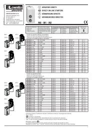
Masa 470g Weight 470gNormy i uznaniaReference standardsIEC/EN 6<strong>10</strong><strong>10</strong>-1, IEC/EN 55011, EN 50082-2, IEC/EN 60028-2-61,IEC/EN 60068-2-6 (LROS-Lloyd’s Register Of Shipping), IEC/EN 60068-2-52(RINA-Italian Naval Register), UL 508 and CSA C22.2_N°14-95 (cULus).IEC/EN 6<strong>10</strong><strong>10</strong>-1, IEC/EN 55011, EN 50082-2, IEC/EN 60028-2-61,IEC/EN 60068-2-6 (LROS-Lloyd’s Register Of Shipping), IEC/EN 60068-2-52 (RINA-Italian Naval Register), UL 508 and CSA C22.2_N°14-95 (cULus).Schematy połączeńWiring diagramsSchemat połączeń trójfazowy generatora z wstępnie wzbudzoną ładowarką alternatorowąWiring diagram for three-phase generating set with pre-energised battery charger alternatorDoc: MHPL_GB201A0206.doc 13/02/2007 p. 11 / 12
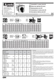
Schemat dla podłączenia jednofazowegoWiring for single-phase generating setSchemat połączeń generatora z magnetoelektryczną ładowarką alternatorowąWiring for generating set with permanent magnet battery charger alternatorC.B. REG.Podłączenie zacisków (widok od tyłu)Terminal block connections (rear view)1.1MAINS1.2 1.31.4GENERATOR2.1 2.2 2.3NC L1 L2-N L3NOL1L2-N* - Nie używane* - Not usedSTARTDETECT.DC OUTPUTRELAY<strong>10</strong>0-415VAC5 0 / 60 HzDIGITAL INPUTS5.15.26.16.26.36.43.13.33.43.53.63.73.8* 4.1* 4.2* 4.3BATTERY12/24 VDC+ ---RS232* 6.5* 6.6* 3.2Wymiary ogólne i wycięcia w paneluOverall dimensions and panel cutout91,0096,0094,0082,0091,0096,00 96.00Doc: MHPL_GB201A0206.doc 13/02/2007 p. 12 / 12