Lecture 10: Synchronous Sequential Circuits Design 1 ... - CS-CSIF
Lecture 10: Synchronous Sequential Circuits Design 1 ... - CS-CSIF
Lecture 10: Synchronous Sequential Circuits Design 1 ... - CS-CSIF

Create successful ePaper yourself
Turn your PDF publications into a flip-book with our unique Google optimized e-Paper software.
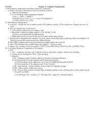
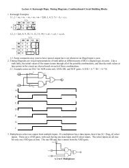
<strong>Lecture</strong> <strong>10</strong>: <strong>Synchronous</strong> <strong>Sequential</strong> <strong>Circuits</strong> <strong>Design</strong>1. General FormInput Combinational Flip-flops Combinational OutputCircuitCircuitClock1.1. Moore type has outputs dependent only on the state, e.g. ripple counters, and shift registers.1.2. Mealy type has outputs dependent on both the state and the input (additional dashed line in the diagram). If theinput is not clocked, then the output may change at any time during a clock cycle.2. Basic <strong>Design</strong> Steps2.1. For this demonstration we will create an edge detecting circuit. For this, we will define an edge as a position in astring of 0’s and 1’s where a 0 is adjacent to a 1. Essentially, this an XOR of adjacent bits. Since this involvesremembering the previous value, we will have different states of the machine.2.2. State Transition Diagram minimizing the number of states.2.2.1. We convert the word description that has states based on patterns of inputs, and transitions between statesbased on individual input values.2.2.2. For our diagram, we will have S i as our start state, and label each state as S xy where x is the previous bit, and yis the current bit. This system ensures that each state has a unique label, and minimizes the number of states.The values inside each state are the output of the circuit, where 0 indicates no edge, and 1 indicates an edgewas detected.<strong>10</strong>S 0 0 S 00 1 S 0<strong>10</strong> 0 0 11S i <strong>10</strong> 0 01 S 1 1 S 11 0 S <strong>10</strong>0 0 1<strong>10</strong>2.3. State Table = a table that lists all transitions from each present state to the next state for different values of theinput signal. Note that the output z is specified with respect to the present state, and x is the next input.Present StateNext State Outputx = 0 x = 1 zi 0 1 00 00 01 01 <strong>10</strong> 11 000 00 01 001 <strong>10</strong> 01 1<strong>10</strong> 00 01 111 <strong>10</strong> 11 02.4. Choice of Flip-Flops and Derivation of Next-State and Output Expressions2.4.1. For example we will keep things simple, and choose to use DFF.2.4.2. Moore Model
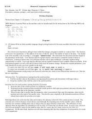
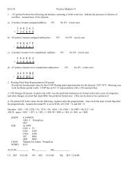
2.4.2.1. Assign binary codes to each state. Since we have seven states, we will need three DFF to represent thepossible states. We will have A, B, and C as the present state of the corresponding flip-flopsPresent StateBinary Present State Input Next State OutputCode A B C x A B C zi 000 0 0 0 0 0 0 1 0i 000 0 0 0 1 0 1 0 00 001 0 0 1 0 0 1 1 00 001 0 0 1 1 1 0 0 01 0<strong>10</strong> 0 1 0 0 1 0 1 01 0<strong>10</strong> 0 1 0 1 1 1 0 000 011 0 1 1 0 0 1 1 000 011 0 1 1 1 1 0 0 001 <strong>10</strong>0 1 0 0 0 1 0 1 <strong>10</strong>1 <strong>10</strong>0 1 0 0 1 1 1 0 1<strong>10</strong> <strong>10</strong>1 1 0 1 0 0 1 1 1<strong>10</strong> <strong>10</strong>1 1 0 1 1 1 0 0 111 1<strong>10</strong> 1 1 0 0 1 0 1 011 1<strong>10</strong> 1 1 0 1 1 1 0 02.4.2.2. Create K-Map for each flip-flop based on input and present state.AABBABCAB00 01 11 <strong>10</strong>00 01 11 <strong>10</strong>00 01 11 <strong>10</strong>00 0 1 1 <strong>10</strong>0 0 0 0 000 1 1 1 <strong>10</strong>1 0 1 1 1Cx01 1 1 1 <strong>10</strong>1 0 0 0 011 1 1 d 1CxCx11 0 0 d 011 0 0 d 0<strong>10</strong> 0 0 d 0<strong>10</strong> 1 1 d 1<strong>10</strong> 1 1 d 1A = BC̅ + AC̅ +CxB = C̅x + Cx̅C= x̅2.4.2.3. Use derivations from the K-maps to design initial combinational circuit.2.4.2.4. Create a K-Map based on flip-flops to determine the output combinational circuit.zAB00 01 11 <strong>10</strong>0 0 0 0 1C1 0 0 0 1z = AB2.4.3. Mealy model usually involves less circuitry, and does here.2.4.3.1. Just need two DFFs to remember previous bit and then XOR with input!