MICOM-3F/3T/3R HF-SSB Transceivers - Mobat-USA
MICOM-3F/3T/3R HF-SSB Transceivers - Mobat-USA
MICOM-3F/3T/3R HF-SSB Transceivers - Mobat-USA
- No tags were found...

Create successful ePaper yourself
Turn your PDF publications into a flip-book with our unique Google optimized e-Paper software.
<strong>MICOM</strong>-<strong>3F</strong>/<strong>3T</strong>/<strong>3R</strong><strong>HF</strong>-<strong>SSB</strong> <strong>Transceivers</strong>Owner’s GuidePart I - Operation & Installation6886867J01A
<strong>MICOM</strong>-<strong>3F</strong>/<strong>3T</strong>/<strong>3R</strong><strong>HF</strong>-<strong>SSB</strong> <strong>Transceivers</strong>MOBAT <strong>USA</strong>1720 West Paul Dirac DriveTallahassee, 32310 FLUnited States of AmericaOwner’s GuidePart I – Operation & InstallationCat. No. 6886867J01A
Table of ContentsTable of ContentsIntroduction .....................................................................................................................1<strong>MICOM</strong>-3 <strong>HF</strong>-<strong>SSB</strong> Radio Features......................................................................2<strong>MICOM</strong>-3 Options and Accessories....................................................................<strong>3F</strong>amiliarization with <strong>MICOM</strong>-3 Radios..............................................................................4<strong>MICOM</strong>-<strong>3F</strong> Front Panel......................................................................................4<strong>MICOM</strong>-<strong>3T</strong> Front Panel......................................................................................5<strong>MICOM</strong>-<strong>3R</strong> Front Panel .....................................................................................6Rear Panel (All Models) ......................................................................................7LCD Display Functions .......................................................................................8General Procedures............................................................................................10Using the External (USB) Keyboard Option (<strong>MICOM</strong>-<strong>3F</strong>/<strong>3R</strong> only) .......................1<strong>3T</strong>he Menu ..........................................................................................................14Basic Operating Instructions .............................................................................................16Turning the Radio On and Off............................................................................16Transmitting and Receiving.................................................................................17Using the Channel Mode....................................................................................18Using the Frequency Mode ................................................................................22Using the Scan Mode .........................................................................................30Using the BIT Mode ...........................................................................................31Locking the Radio...............................................................................................32Changing the Password.......................................................................................33Using Automatic Link Establishment (ALE).........................................................................34ALE Capabilities and Features.............................................................................34Using ALE Functions in the Channel Mode .........................................................43Entering the ALE Mode.......................................................................................4<strong>3R</strong>eceiving and Transmitting Calls in ALE Mode....................................................45Using the Programming Mode ..........................................................................................78Programming the Radio Parameters ..................................................................................81Programming Channels.......................................................................................82Selecting Radio Parameters.................................................................................84Setting Radio Options.........................................................................................86ALE Programming .............................................................................................................87Programming Nets..............................................................................................88Setting the Net Options ......................................................................................90Directory Parameters..........................................................................................90AMD Message Configuration ..............................................................................91ALE Options Configuration .................................................................................91Auto Dial Parameters..........................................................................................93Pagei
AcronymsAcronymsAGCALEAMDAMEARQBITECWDSPDTCXOFECFSKGNDGPS<strong>HF</strong>HSMLEDLQALSBLSMMCWMRCOCXOPEPPLLPTTRGCRSSRTTYSINAD<strong>SSB</strong>USBVPVSWRXMITAutomatic Gain ControlAutomatic Link EstablishmentAutomatic Message DisplayAmplitude Modulation EquivalentAutomatic Repeat RequestBuilt-In Test EquipmentContinuous WaveDigital Signal ProcessingDigitally Temperature Controlled Crystal OscillatorForward Error CorrectionFrequency Shift KeyingGroundGlobal Positioning SystemHigh FrequencyHigh Speed ModemLight Emitting DiodeLink Quality AnalysisLower Side BandLow Speed ModemModulated Continuous Wave<strong>MICOM</strong> Radio Control ApplicationOven Controlled Crystal OscillatorPeak Envelope PowerPhase Lock LoopPush To TalkReceiver Gain ControlRadio Service SoftwareRadio Telex TeletypeSignal to Signal Noise Distortion RatioSingle Side BandUpper Side BandVoice PrivacyVoltage Standing Wave RatioTransmitiii
<strong>MICOM</strong>-<strong>3F</strong>/<strong>3T</strong>/<strong>3R</strong> <strong>HF</strong>-<strong>SSB</strong> Owner’s GuidePerformance Specifications<strong>MICOM</strong>-<strong>3F</strong> – Model M90AMNOKV5-K<strong>MICOM</strong>-<strong>3T</strong> – Model M91AMNOKV5-K<strong>MICOM</strong>-<strong>3R</strong> – Model M95AMNOKV5-KGeneral Transmit Frequency Range 1.6 to 30 MHzReceive Frequency RangeRF Input ImpedanceNumber of ChannelsScanningALE0.1 to 30 MHz (0.1 to 1.6 MHz reducedperformance)50 Ω200 simplex or half duplex, user programmable5 groups with up to 100 channels per group,including 1 guard channel.Programmable scan rate: 1 to 5 sec. perchannel, in 1 sec. stepsPer FED-STD-1045B and MIL-STD-188-141B,JITC certifiedFrequency Stability 0.6 ppm (0.1 ppm optional) @ -30° to 60°CFrequency Drift (Aging)Synthesizer Lock TimeFrequency ResolutionOperating Temperature RangeStorage Temperature Range1 ppm/year10 msec. max.10 Hz-30° to +60°C-40° to +85°CHumidity Max. 95% @ 50°CRemote Control InterfaceModes of OperationOperating VoltageDimensions<strong>MICOM</strong>-<strong>3F</strong><strong>MICOM</strong>-<strong>3R</strong><strong>MICOM</strong>-<strong>3T</strong>RS-232C (optional)• ]3E <strong>SSB</strong>• R3E PILOT• H3E AME• J2A CW• J2B RTTY, ARQ, FEC, PACKET, MCW• B8C FAX, DATA, FSK13. 8 VDC ±20%, negative ground92 H × 302 W × 270 D mm(3.7 H × 11.9 W × 10.7 D inch)92 H × 302 W × 285 D mm(3.7 H × 11.9 W × 11.3 D inch)92 H × 302 W × 285 D mm(3.7 H × 11.9 W × 11.3 D inch)iv
<strong>MICOM</strong>-<strong>3F</strong>/<strong>3T</strong>/<strong>3R</strong> <strong>HF</strong>-<strong>SSB</strong> Owner’s GuideTransmitterOutput PowerReduced Power LevelsAudio BandwidthVoiceCWLow Speed DataHigh Speed DataAudio Bandwidth RippleIntermodulationHarmonic EmissionsSpurious EmissionsCarrier SuppressionUndesired Sideband Suppression125 W P.E.P and average25 W, 62 W, 100 W (MRC or RSSprogrammable)350 to 2700 Hz at -6 dB650 to 1150 Hz1450 to 1950 Hz350 to 3300 Hz (see Note 2 on page vii)3 dBAudio Distortion 2.5%• -31 dB/P.E.P• -35 dB/P.E.P typical (see Note 1 on page vii)• -64 dB/P.E.P• -70 dB/P.E.P typical (see Note 1 on page vii)• -64 dB/P.E.P• -70 dB/P.E.P typical (see Note 1 on page vii)-50 dB/P.E.P-55 dB/P.E.P1/2 Power Microphone Sensitivity 25 to 125mV (RMS)/600 ΩHum & RippleInband NoiseTX/RX Switching TimeTx Tuning Adjustments-50 dB-60 dB (30 Hz BW)10 msecNoneReceiver Sensitivity (SINAD) <strong>SSB</strong> • 0.5 µV for 10 dB SINAD• 0.35 µV typical (see Note 1 on page vii)• 0.1 to 1.6 MHz with reduced performance1/2 Rated Power Sensitivity 1 µV for 2.5W audio at speakerSelectivityImage RejectionIF RejectionUndesired Sideband RejectionSpuriousIntermodulationCrossmodulationDesensitizationReciprocal MixingAudio Power at Speaker-6 dB @ 350 to 2700 Hz-60 dB @-1 kHz; +4 kHz-80 dB-85 dB-55 dB @ -1 kHz-80 dB-80 dB-100 dB @ 100 kHz-100 dB @ 100 kHz-100 dB @ 100 kHz5W @ 2.5% distortionvi
Performance SpecificationsControlsRGC RangeRGC Time ConstantsVoiceDataSquelchClarifier RangeReceiver Tuning AdjustmentsPreselector SectionsMaximum Antenna Input5 µV to 1V (2 dB change in output level)Attack time 10 msecRelease time 1500 msecAttack time 10 msecRelease time 10 msecConstant SINAD (digital)±200 Hz in 10 Hz steps (see Note 2 on pagevii)NoneSub-octave (1.6 MHz to 30 MHz range)20 kV transient, 100V RMS for 2 minutesStandard and optional: Volume, on/off, scroll, squelch, scan, USB/LSB, call,monitor, priority, function and accessory/programming connectorNote 1: Values noted as "Typical" are valid over 90% or more of the frequency range.Note 2: Optional for authorized dealers only.Specifications subject to change without notice.vii
<strong>MICOM</strong>-<strong>3F</strong>/<strong>3T</strong>/<strong>3R</strong> <strong>HF</strong>-<strong>SSB</strong> Owner’s GuideWarnings, Cautions and NotesThe following notations are used to place special emphasis on procedures, or to call attention toprecautionary measures.WarningAn operating procedure, practice and so forth, which if not followedcorrectly, could result in personal injury, or loss of life.CautionBEFORE USING THIS RADIO, READ THIS BOOKLET WHICH CONTAINSIMPORTANT OPERATING INSTRUCTIONS FOR SAFE <strong>USA</strong>GE AND RFENERGY AWARENESS AND CONTROL INFORMATION FORCOMPLIANCE WITH RF ENERGY EXPOSURE LIMITS IN APPLICABLENATIONAL AND INTERNATIONAL STANDARDS.NoteAn operating procedure, condition and so forth, to which special attention shouldbe paid.General Safety PrecautionsThe following are general safety precautions that are not related to any specific procedures andtherefore do not appear elsewhere in this publication. These are recommended precautions thatpersonnel must understand and apply, in addition to the precautions listed in the Information for Safe,Efficient Operation section (page ix).Do not touch the antenna and the RF connectors when the transceiveroperates.WarningHighVoltageDuring transmission, high RF voltages appear at the RF connectors, theantenna cables, and on the antenna itself. These voltages may causesevere injury or even death on contact.Operating and maintenance personnel must be familiar with theapplicable safety requirements before attempting to install or operate thetransceiver. Severe injury or death could result from failure to complywith the safety practices.viii
Information for Safe, Efficient OperationInformation for Safe, Efficient OperationProduct Safety and RF Exposure for Mobile Two-Way RadiosInstalled in Vehicles or as Fixed Site Control StationsCautionBEFORE USING THIS RADIO, READ THIS BOOKLET WHICH CONTAINSIMPORTANT OPERATING INSTRUCTIONS FOR SAFE <strong>USA</strong>GE AND RFENERGY AWARENESS AND CONTROL INFORMATION FORCOMPLIANCE WITH RF ENERGY EXPOSURE LIMITS IN APPLICABLENATIONAL AND INTERNATIONAL STANDARDS.The information provided in this document supersedes the general safety information contained inuser guides published prior to February 2002.Compliance with RF Energy Exposure StandardsNOTICEThis radio is intended for use in occupational/controlled applications where users havebeen made aware of the potentional for exposure and can exercise control over theirexposure. This radio device is NOT authorized for general population, consumer orsimilar use.MOBAT <strong>USA</strong>1720 West Paul Dirac DriveTallahassee, 32310 FLUnited States of Americaix
<strong>MICOM</strong>-<strong>3F</strong>/<strong>3T</strong>/<strong>3R</strong> <strong>HF</strong>-<strong>SSB</strong> Owner’s GuideFederal Communication Commission RegulationsThe FCC has established limits for safe exposure to radio frequency (RF) emissions from mobiletwo-way radios. The FCC requires manufacturers to demonstrate compliance with RF exposurelimits before mobile two-way radios can be marketed in the U.S. When two-way radios areapproved for occupational/controlled environment exposure limits, the FCC requires users to befully aware of, and exercise control over, their exposure. Awareness and control of RF exposurecan be accomplished by education or training through appropriate means such as informationand instructions in user manuals or safety booklets, or other appropriate means. This user safetybooklet includes useful information about RF exposure and helpful instructions on how tocontrol your RF exposure.Your two-way radio is designed and tested to comply with a number of national and internationalstandards and guidelines (listed below) regarding human exposure to radio frequency electromagneticenergy. This radio complies with the IEEE (FCC) and ICNIRP exposure limits foroccupational/controlled RF exposure environments at usage factors of up to 50% talk-50% listen.In terms of measuring RF energy for compliance with FCC exposure guidelines, your radio radiatesmeasurable RF energy only while it is transmitting (during talking), not when it is receiving(listening) or in standby mode.Your two-way radio complies with the following RF energy exposure standards and guidelines:• United States Federal Communications Commission, Code of Federal Regulations; 47CFR part 2sub-part J• American National Standards Institute (ANSI) / Institute of Electrical and Electronic Engineers(IEEE) C95.1-1992• Institute of Electrical and Electronic Engineers (IEEE) C95.1-1999 Edition• International Commission on Non-Ionizing Radiation Protection (ICNIRP) 1998• Ministry of Health (Canada) Safety Code 6: Limits of Human Exposure to RadiofrequencyElectromagnetic Fields in the Frequency Range from 3 kHz to 300 GHz, 1999• Australian Communications Authority Radiocommunications (Electromagnetic Radiation –Human Exposure) Standard, 2001• ANATEL, Brasil Regulatory Authority, Resolution 256 (April 11, 2001). Additional Requirementsfor SMR, Cellular and PCS Product Certification.x
Information for Safe, Efficient OperationCompliance and Control Guidelines and Operating Instructions forMobile Two-Way Radios Installed in VehiclesTo control your exposure and ensure compliance with the occupational/controlled environmentexposure limits, always adhere to the following procedures:• To transmit (talk), push the Push-To-Talk (PTT) button; to receive, release the PTT button.Transmit only when people outside the vehicle are at least 7 feet from a properly installed,externally-mounted antenna.• Install mobile antennas at the center of the roof or the center of the trunk deck per specificguidelines and instructions in the Radio Installation Manual. These mobile antennainstallation guidelines are limited to metal body vehicles.Use only the approved, supplied antenna or an approved replacement antenna. Use ofnon-approved antennas, modifications, or attachments could damage the radio and may violateFCC regulations.xi
<strong>MICOM</strong>-<strong>3F</strong>/<strong>3T</strong>/<strong>3R</strong> <strong>HF</strong>-<strong>SSB</strong> Owner’s GuideCompliance and Control Guidelines and Operating Instructions forMobile Two-Way Radios Installed as Fixed Site Control StationsIf mobile radio equipment is installed at a fixed location and operated as a control station or as afixed unit, the antenna installation must comply with the following requirements in order to ensureoptimal performance and compliance with the RF energy exposure limits in the standards andguidelines listed on page x:• The antenna should be mounted outside the building on the roof or a tower if at all possible.• As with all fixed site antenna installations, it is the responsibility of the licensee to manage the sitein accordance with applicable regulatory requirements and may require additional complianceactions such as site survey measurements, signage, and site access restrictions in order to ensurethat exposure limits are not exceeded.Electromagnetic Interference/CompatibilityNoteNearly every electronic device is susceptible to electromagnetic interference (EMI)if inadequately shielded, designed, or otherwise configured for electromagneticcompatibility. It may be necessary to conduct compatibility testing to determine ifany electronic equipment used in or around vehicles or near fixed site antenna issensitive to external RF energy or if any procedures need to be followed toeliminate or mitigate the potential for interaction between the radio transmitterand the equipment or device.FacilitiesTo avoid electromagnetic interference and/or compatibility conflicts, turn off your radio In anyfacility where posted notices instruct you to do so. Hospitals or health care facilities may be usingequipment that is sensitive to external RF energy.VehiclesTo avoid possible interaction between the radio transmitter and any vehicle electronic controlmodules, for example, ABS, engine, or transmission controls, the radio should be installed only by anexperienced installer and that the following precautions be used when installing the radio:1. Refer to the manufacturer's instructions or other technical bulletins for recommendations onradio installation.2. Before installing the radio, determine the location of the electronic control modules and theirharnesses in the vehicle.3. Route all radio wiring, including the antenna transmission line, as far away as possible from theelectronic control units and associated wiring.xii
Information for Safe, Efficient OperationDriver SafetyCheck the laws and regulations on the use of radios in the area where you drive. Always obey them.When using your radio while driving, please:• Give full attention to driving and to the road.• Pull off the road and park before making or answering a call if driving conditions so require.Operational WarningsFor Vehicles with an Air BagWarningDo not mount or place a mobile radio in the area over an air bagdeployment area. Air bags inflate with great force. If a radio is placed inthe air bag deployment area and the air bag inflates, the radio may bepropelled with great force and cause serious injury to occupants of thevehicle.Potentially Explosive AtmospheresTurn off your radio prior to entering any area with a potentially explosiveatmosphere. Sparks in a potentially explosive atmosphere can cause anexplosion or fire resulting in bodily injury or even death.The areas with potentially explosive atmospheres include fueling areassuch as below decks on boats, fuel or chemical transfer or storagefacilities, and areas where the air contains chemicals or particles such asgrain, dust or metal powders. Areas with potentially explosiveatmospheres are often, but not always, posted.Blasting Caps and Blasting AreasWarningTo avoid possible interference with blasting operations, turn off warningyour radio when you are near electrical blasting caps, in a blasting area,or in areas posted: "Turn off two-way radio". Obey all signs andinstructions.For radios installed in vehicles fueled by liquefied petroleum gas, refer tothe (U.S.) National Fire Protection Association standard, NFPA 58, forstorage, handling, and/or container information. For a copy of the LP-gasstandard, NFPA 58, contact the National Fire Protection Association, OneBattery Park, Quincy, MA.xiii
<strong>MICOM</strong>-<strong>3F</strong>/<strong>3T</strong>/<strong>3R</strong> <strong>HF</strong>-<strong>SSB</strong> Owner’s GuideIntentionally Left Blankxiv
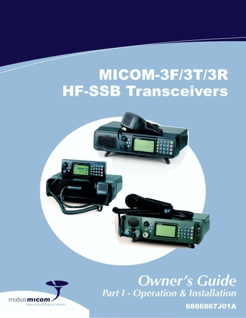
IntroductionIntroductionWelcome to the <strong>MICOM</strong>-3 <strong>HF</strong>-<strong>SSB</strong> radio family! Your choice of a <strong>MICOM</strong>-3 radio means you haveselected the highest of standards in design, quality, and performance. This manual is designed toacquaint you with the features, care, and installation of the following <strong>MICOM</strong>-3 radios to better serveall your communication needs:<strong>MICOM</strong>-<strong>3F</strong>Transceiver for long range wireless voice, fax, data andemail communication, with built-in front panel, for fixedand mobile use.<strong>MICOM</strong>-<strong>3T</strong>Transceiver for trunk mounting with separate control box,saves valuable cabin space in mobile use.<strong>MICOM</strong>-<strong>3R</strong>Ruggedized transceiver with military handset andconnectors, for fixed and mobile use in applicationsrequiring the utmost dependability and reliability.In Appendix A, you will also find information on the micomTrooper 3, the 5-to-50W backpacktransceiver version of <strong>MICOM</strong>-3 transceiver, and its Battery Charger, FLN9541.For convenience, the manual is divided into two Parts:• Part I – Operation and Installation (this Part) presents the information you need to familiarizewith <strong>MICOM</strong>-3 radios and operate them efficiently. It also explains how to install your radio setand correct most of the problems that may occur during its operation.• Part II – Manual Programming explains in detail how to program manually any radio parameterfrom the <strong>MICOM</strong>-3 front panel, instead of using the dedicated <strong>MICOM</strong>-3 Radio ControlApplication (MRC) or Radio Service Software (RSS). For this purpose, you will find in this Partexplanations and step-by-step instructions that expand the general radio programming of Part I.NoteIn both Parts of this manual, the generic term <strong>MICOM</strong>-3 is used for informationapplicable to all the transceiver versions. The complete transceiver designation isused only for information applicable to a specific equipment version.1
<strong>MICOM</strong>-<strong>3F</strong>/<strong>3T</strong>/<strong>3R</strong> <strong>HF</strong>-<strong>SSB</strong> Owner’s Guide<strong>MICOM</strong>-3 <strong>HF</strong>-<strong>SSB</strong> Radio Features• Digital Signal Processing (DSP)• Built-in Test Equipment (BITE)• RF power indications• 200 channel capacity, simplex or half-duplex• Channel scan or Automatic Link Establishment (ALE) per MIL-STD-188-141B/FED-STD-1045• MultiNet function for seamless integration of different <strong>HF</strong> radio networks in one network• Automatic IF shift• Clarifier• Voice-activated digital squelch• Excellent transmitter and receiver performance• High frequency stability option• DSP software can be upgraded to incorporate future options and new technologies• Large LCD display and optional support for multiple languages• MIL-STD-810C, D and E compliance.Transmitter FeaturesThe maximum output power of the transmitter is 125 W PEP (Peak Envelope Power). The averagetransmission duty cycle is up to 1:4, thus enabling even CW (Continuous Wave) signals to betransmitted at the maximum available power. Output power can be preprogrammed to one of fourlevels: 25W, 62.5W, 100W and 125W. Accurate sensors are used to keep the output power at theselected value.The transmitter includes thermal protection. If, for any reason, the transmitter internal temperatureexceeds the maximum permitted temperature, the output power is automatically reduced to avoidany fault due to excessive heat. Antenna mismatch protection is also included. If the VSWR (VoltageStanding Wave Ratio) rises to more than 2:1, the transmission will be inhibited to avoid damage anda message will be displayed.Receiver FeaturesThe radio utilizes digital signal processing for implementing most of the receiver functions, e.g.,demodulation, narrow band filtering, automatic gain control, noise blanking, tunable notch filter,squelch, etc. An automatic digital noise blanker is activated whenever repetitive noise (e.g., ignitionspikes) is encountered in the received signal. The digital syllabic (speech identifier) squelch isactivated whenever speech is identified, thus opening the audio path. However, if speech is notreceived, the audio path is muted, thus preventing background noise from disturbing the operator.Frequency SourcesTwo types of frequency sources are available for the <strong>MICOM</strong>-3 radio. The standard 0.6 ppm DTCXOfrequency source which assures a frequency accuracy of better than ±18 Hz. For frequencies lowerthan 10 MHz, it assures a frequency accuracy of better than ±6 Hz. When higher frequency accuracyis required, the G112 0.1 ppm OCXO frequency source can be ordered. It will assure a frequencyaccuracy of better than ±3 Hz at 30 MHz.2
IntroductionPower SourceThe radio is designed for 13.8 V ±20% negative-ground operation and may be connected to astandard 12 V battery.CW Keying OperationWhen the CW key is pressed, the radio transmits a continuous wave (at the full programmed power)and stops transmission when the key is released. CW keying operation is enabled by connecting aMorse key to the accessories connector. If you wish to operate CW keying with external headphones,the S809 Interface cable can be used, thus enabling a standard PL55 headphone and standard PL99Morse key to be connected to the accessories connector.Programmable FeaturesThe radio can be programmed using a PC running the <strong>MICOM</strong> Radio Control Application (MRC) orthe Radio Service Software (RSS). The following radio features can be programmed:• Up to 200 simplex/half duplex channels supporting <strong>SSB</strong> (J3E), AME (H3E), or Pilot (R3E) modes.• Up to four levels of output power (up to 125W PEP and average).• Five scanning groups of up to 200 channels, each with guard channel.For further details, refer to “<strong>MICOM</strong> Radio Control Application Owner’s Guide”, Publication6886869J01, or to “<strong>MICOM</strong>-3 <strong>HF</strong>-<strong>SSB</strong> Transceiver, RSS User’s Guide”, Publication 6886867J01.<strong>MICOM</strong>-3 Options and Accessories• RS-232 remote control interface• Linear power amplifier interface• Phone patch interface• Data/fax modem interface• MRC or RSS for PC• High (0.1 ppm) frequency accuracy• micomLink• VP-116 voice privacy unit• <strong>HF</strong> vocoder unit• Internal GPS receiver• ISB operation• Desktop microphone• Automatic antenna tuners• Continuous duty data transmission kit• AC power supply• 500 W linear power amplifier• 1 kW linear power amplifier• Antennas and grounding• CW key and headphones• External speaker.3
<strong>MICOM</strong>-<strong>3F</strong>/<strong>3T</strong>/<strong>3R</strong> <strong>HF</strong>-<strong>SSB</strong> Owner’s GuideFamiliarization with <strong>MICOM</strong>-3 Radios<strong>MICOM</strong>-<strong>3F</strong> Front PanelON/OFF & Volume ControlTurns radio on and offand controls thespeaker volumeInternal SpeakerUp/Down KeysUsed to scrollvaluesDisplayNot usedTx IndicatorLights whenradio istransmittingMENU KeyDisplays themain menu<strong>MICOM</strong>-<strong>3F</strong>1F2F<strong>3F</strong>41 ? @ /G4HIPR7 QS*2 3ABC5 6JKLDEFMNOT Y8 UV9WZ X0 #MENUPEscALARMGPSESC KeyCancels thelast actionand reverts tothe previousscreenNot usedENTER KeySaves theselectionand/or valueConnector forOptionalExternal USBKeyboardMovecursor tothe leftMicrophoneConnectorConnector formicrophonewith PTT andcable to RSSMORE KeyDisplays additionalmenu options whenappear in the display.ÛAlso serves to movethe cursor to the rightFunction KeysActivate differentfunctions, asdisplayed nextto each keyKeypadA set of keysused to enteralphanumericdata4
Familiarization with <strong>MICOM</strong>-3 Radios<strong>MICOM</strong>-<strong>3T</strong> Front PanelON/OFF & Volume ControlTurns radio on and offand controls thespeaker volumeMovecursor tothe leftMicrophoneConnectorConnector formicrophonewith PTT andcable to RSSUp/Down KeysUsed to scrollvalues<strong>MICOM</strong>-3DisplayMORE KeyDisplays additionalmenu options whenÛappear in the display.Also serves to movethe cursor to the rightNot usedF1F2F<strong>3F</strong>41 ? @/G4 HIPR7 QS*2 3ABC5 6JKL8 9TUVDEFMNOY WZ X0 #Function KeysActivate differentfunctions, asdisplayed nextto each keyTx IndicatorLights whenradio istransmittingMENUPEscALARMGPSMENU KeyDisplays themain menuESC KeyCancels thelast actionand reverts tothe previousscreenNot usedENTER KeySaves theselectionand/or valueKeypadA set of keysused to enteralphanumericdata5
<strong>MICOM</strong>-<strong>3F</strong>/<strong>3T</strong>/<strong>3R</strong> <strong>HF</strong>-<strong>SSB</strong> Owner’s Guide<strong>MICOM</strong>-<strong>3R</strong> Front PanelON/OFF & Volume ControlTurns radio on and offand controls thespeaker volumeInternal SpeakerUp/Down KeysUsed to scrollvaluesDisplayNot usedTx IndicatorLights whenradio istransmittingMENU KeyDisplays themain menuESC KeyCancels thelast actionand reverts tothe previousscreenCOM<strong>MICOM</strong>-<strong>3F</strong>1F2F31 ? @/G4 HIPR7 QS2 3ABC5 6JKLDEFMNOT Y8 UV9WZ XMENUPEscALARMGPSUSBConnectorforOptionalExternal USBKeyboardF4*0 #Not usedAUDIOMovecursor tothe leftInternal SpeakerON/OFF SwitchMORE KeyDisplays additionalmenu options whenÛappear in the display.Also serves to movethe cursor to the rightFunction KeysActivate differentfunctions, asdisplayed nextto each keyKeypadA set of keysused to enteralphanumericdataENTER KeySaves theselectionand/or valueAudioConnectorsConnectors forexternal speakerand handsetMicrophoneConnectorConnector formicrophonewith PTT andcable to RSS6
Familiarization with <strong>MICOM</strong>-3 RadiosRear Panel (All Models)5No. Item Function1 Antenna connector N-type female connector for connection to antenna or optional linear poweramplifier2 Accessoriesconnector44-pin male D-type connector, used to connect the radio to external accessoriessuch as: personal computers, MRC, external modems, Morse key, etc.3 DC connector 3-pin D-type male connector for connection of DC power source4 Grounding screw Connection of ground to the radio case5 GPS antennaconnectorConnection to the GPS antenna (for <strong>MICOM</strong>-3 with the optional GPS receiver)7
<strong>MICOM</strong>-<strong>3F</strong>/<strong>3T</strong>/<strong>3R</strong> <strong>HF</strong>-<strong>SSB</strong> Owner’s GuideLCD Display FunctionsDisplay Organization12<strong>MICOM</strong>-3CH 6F 16,000.00NFSQ BW3.3AGCUSBNBCLARPWRMODEIAGCBW63 4 57No. Designation Description1 Mode indicator Indicates the current working mode2 Work area Displays information on the current working mode and the selected operatingparameters3 Transmit level indicator In the transmit mode, displays the relative transmitter power4 Receive level indicator In the receive mode, displays the relative power of the received signal5 Tx Bar Appears when the radio is transmitting6 More options icon The presence of this icon indicates that more options can be displayed in theoptions area. Press the MORE key when this icon appears to see more menuoptions7 Options display area Displays a list of options you can select in the current working modeOther IndicationsThe following indications may appear in the work area of the LCD display to indicate functions thatare active when you work with <strong>MICOM</strong>-3.Indication MeaningUSBLSBSQMONAGCBWNBCLARNFUsing upper sideband for transmission and receptionUsing lower sideband for transmission and receptionSquelch is active: the speaker is turned on only when the radio identifies speech, to preventreception noise from being heard (see Note)When using ALE, indicates that the speaker is normally off, and is automatically turned on whenthe link is established (see Note)Non-standard AGC mode (AGC off, or fast AGC) has been selectedNon-standard bandwidth has been selected (the bandwidth appears next to the BW indicator forexample, 3.3 (3.3 kHz) in the display shown above)Noise blanker is activeClarifier is active (meaning that you selected a frequency deviating from the nominal channelfrequency)Notch filter is activeNoteFor the <strong>MICOM</strong>-<strong>3R</strong>, the squelch and monitor functions also effect the handset.8
Familiarization with <strong>MICOM</strong>-3 RadiosRF Level IndicationsReflectedPowerIndicationStrong received signalWeak received signalFull transmit power(125W)Actual transmit powerLow transmit powerMeaningRelative indication of received RF signal, displayed when the radio is inthe receive modeTransmit bar appears when the radio is switched to the transmit mode(for example, when the PTT is pressed). Its length indicates the <strong>MICOM</strong>-3 maximum transmit power, 125 W.The height of the inverted triangle indicates the relative transmitteroutput (forward) power. It fluctuates as a result of modulation.The relative reflected power is indicated by the base line: its lengthindicates the fraction of power reflected because of antenna VSWR (thelength should be small relative to the total height of the indicator, whichis proportional to the forward power)Audible IndicationsThe user can configure the <strong>MICOM</strong>-3 to generate audible tones to indicate events related to theradio operating conditions. The tone volume, low or high, may also be set using the RSS, MRC or byprogramming from the front panel.EventDescriptionValid key pressing Beep sounds when a key is pressed, to indicate that the key pressing has beenaccepted. No beep – no action.PTT release A beep sounds on the remote radio to indicate that the local PTT button hasbeen released.ALE alerts During ALE operation, beeps alert you to events you should be aware off, e.g.,link establishment/disconnection etc.9
<strong>MICOM</strong>-<strong>3F</strong>/<strong>3T</strong>/<strong>3R</strong> <strong>HF</strong>-<strong>SSB</strong> Owner’s GuideGeneral ProceduresThis section provides general procedures that will help you start using your <strong>MICOM</strong>-3 radio and getthe most of its advanced features.Most of the activities that can be performed by you (selection of operating mode, status display,programming, testing, etc.) are done using the keypad together with the four navigation keys (up, down,left and right) and the front panel display.To simplify operation, <strong>MICOM</strong>-3 uses soft keys that let you control the radio simply and efficiently,using a menu-driven mode that guides you and helps you make the required selections.“Menu-driven” simply means that whenever you must select a parameter, an operating mode, etc.,you select it from a list of allowed values displayed on the front panel display, thereby reducing thechance of error:• To make the selection, you use navigation keys to reach the desired parameter value oroperation, and then confirm the selection by pressing the ENTER key.• To let you go back to previous options, there is an ESC key.Using the KeypadEach key is imprinted with a numeral and several letters. Thesecharacters are accessed in clockwise order, as follows:• A single key press enters the numeral• Two consecutive key presses enter the first letter• Three consecutive key presses enter the second letter• Four consecutive key presses enter the third letter.• Five consecutive key presses enter the fourth letter.• To enter a blank space, press 0 twice.1 ? @/G4 HI7PRQS*2 3ABCJKL5 6T UV8 9DEFMNOY WZ X0 #MENUPEscALARMGPSWhen entering frequencies, use the * key as a decimal point, if needed. In the ALE mode, the *key is also used to enter the wild-card character (? or @).Note To enter the ampersand @ symbol, press the # key twice. Do not use the 1 ? @ /key.Example: to enter “MIKE 01”:MPress 6 NO twice (for the letter M).PressPressPressG4 H I four times (for the letter I).J5 KL three times (for the letter K).D3 EF three times (for the letter E).Press 0 twice (for the blank space).Press 0 once (for the numeral 0).Press 1 ? @ / once (for the numeral 1).10
Familiarization with <strong>MICOM</strong>-3 RadiosFunction KeysThe function keys F1, F2, F3 and F4 appearing next to the displayare soft keys used to select options which depend on the currentradio mode. The current function of each key is shown in theoptions area of the display, next to the key. For example, on thePROG screen you can press F2 to start programming the ALEparameters.<strong>MICOM</strong>-3PROGRADALELANGF1F2F<strong>3F</strong>4If a certain function key is not used, no label appears next to thekey (see for example F4), and pressing that key has no effect.Scroll (MORE) KeyThe MORE key is used to scroll the options appearing in the options area of the display.Up/Down Scroll KeysThe up and down scroll keys are used to scroll between values that arealready programmed into the radio. For example:• In the Channel mode, pressing the up or down scroll key once letsyou view the previous, respectively next, programmed channel.Pressing either key continuously scrolls the channels in the selecteddirection.• In the Frequency mode, you can change the frequency in thecorresponding direction.• In the radio Programming mode, you can use these keys to scrollamong the programmable parameters.UpDownMoreSelection from List of Predetermined ValuesWhen the parameter you want to select can assume only one of severalpredetermined values, you select the desired value by pressing thefunction keys:• F1 enters the lowest possible value (or OFF)• F4 enters the highest possible value• F2 and F3 increment or decrement the value. When you reach eitherend, the corresponding key disappearsYou cannot use the keypad to enter a value for such parameters.<strong>MICOM</strong>-3PROGADT - 9 SEC110Toggle ModeWhen the function being set can only be toggled on or off, one functionkey will be marked YES and another NO.To expedite turning on and off often-used functions (for example, turn thesquelch on or off) only one key is used. In this case, just press the keyassigned to the function to be toggled: the new state is shown for a fewseconds, and then disappears as it takes effect immediately.<strong>MICOM</strong>-3PROGALE - NOYESNO11
<strong>MICOM</strong>-<strong>3F</strong>/<strong>3T</strong>/<strong>3R</strong> <strong>HF</strong>-<strong>SSB</strong> Owner’s GuideAlphanumeric Edit ModeWhen you need to enter an alphanumeric string in a field, or edit a string, you type the desiredalphanumeric character on the keypad. A blinking cursor _ indicates the location being edited.In addition, the following function keys are available:SAVE (F1) Saves editing changes (equivalent to pressing the ENTER key). (F3)CLR (F4)Numeric Edit ModeUsed to move the cursor backwards and forwards. When you reach either end,the corresponding key disappears.Pressing this key momentarily erases the digit/letter at which the cursor ispresently located, and shifts the entire field one place to the left.Press this key continuously clears the entire field.When you need to enter a number in a field, or edit the number, you type the desired digits on thekeypad. A blinking cursor _ indicates the location being edited.In addition, the following function keys are available:BACK (F3) Erases the last digit.CLR (F4) Erases all newly entered digits and restores the original value.View ModeWhen the string to be displayed is longer than the number of characters that fit in one line (forinstance, with long addresses or messages), the view mode enables scrolling to the rest of the string.The view mode is indicated by the symbol next to one of thefunction keys.<strong>MICOM</strong>-3AMD 001 AMD MESSEDITERASWhen you press , the key functions change:HOME (F1) Scrolls to display the first character of the string. (F3)you press either key continuously, the scrolling continuesat a rate of four characters per second.END (F4) Scrolls to display the last character of the string.<strong>MICOM</strong>-3AMD 01 AMD MESSAWhen you reach the beginning of the string, the HOME (F1) and (F3) and END (F4) function keys disappear.HOMEENDMessage Attached AlertWhen a message is attached to the received call (an option available forALE calls, even if you are using the Channel mode), an exclamation sign !appears to the left of the originating station name.You can view the message contents after you accept the call.<strong>MICOM</strong>-<strong>3F</strong>ROM!ABC12
Familiarization with <strong>MICOM</strong>-3 RadiosUsing the External (USB) Keyboard Option(<strong>MICOM</strong>-<strong>3F</strong>/<strong>3R</strong> only)<strong>MICOM</strong>-<strong>3F</strong> and <strong>MICOM</strong>-<strong>3R</strong> have a USB connector (see pages 4 and 6) for connecting the optionalexternal keyboard with USB connector.NoteWhen you plug in the keyboard while the radio operates, the LCD displays for ashort time DEVICE RM followed by USB KEYBOARD DETECTS. After thesemessages, you can start using the keyboard.While the USB keyboard is connected, you can use it to control the functions normally performedwith the keys on <strong>MICOM</strong>-3 front panel.Moreover, <strong>MICOM</strong>-3 accepts entries from both the USB keyboard and its panel: just do not use themat the same instant.The following table explains the keyboard functions.Keyboard Key <strong>MICOM</strong> Panel Key FunctionESCPEscCancels the last action and reverts to the previous screen.Pressing ESC for a few seconds initiates AllCallF1, F2, F3, F4 F1 F2 F3 F4 Action in accordance with current screenF5 to F12 – No functionENTER keyConfirm action, save the selection and/or valueSHIFT and ↑, or ↓ – Changing the display contrastSHIFT @, #, or * – Use in AllCall, AnyCall or wildcard modes↑, ↓ Use to scroll values←, → Display previous/next menu optionSpace barCreates a spaceBackspace – Moves the cursor to the left. To delete the character, press F4WIN key MENU Display the main menuNumber keys 0 to 9 Used to enter digits in alphanumeric dataCharacter key A to Z Used to enter letters in alphanumeric dataTo stop using the keyboard, disconnect it from the <strong>MICOM</strong>-3 USB connector (the disconnection alsoresults in messages that notify you the keyboard has been disconnected).13
<strong>MICOM</strong>-<strong>3F</strong>/<strong>3T</strong>/<strong>3R</strong> <strong>HF</strong>-<strong>SSB</strong> Owner’s GuideThe MenuThe menu is used to select what you want your radio to do.➤To display the menu:1. Press MENU to display the first part of the Menu screen.You can press the MENU key at any time during any sequenceof operations: that sequence is then discontinued and themenu screen is immediately displayed.<strong>MICOM</strong>-3MENUCHANFREQIALEBITNoteWhen the ALE function is not used, the third item isSCAN.2. Press MORE to scroll to the second part of the Menu screen.<strong>MICOM</strong>-3MENULOCKPROGIPSWDIM3. To select any item, press the function key next to it.➤To exit the menu and return to the previous working mode (e.g., CHAN or FREQ):Press the ESC key. The deeper you are in the menu, the more times you need to press ESC.Selecting the Display Language1. Display the second part of the Menu screen as explained above.<strong>MICOM</strong>-3MENULOCKPROGIPSWDIM2. Press PROG (F2) to enter the Programming mode.<strong>MICOM</strong>-3PROGRADALELANG3. Press the function key next to the desired language.4. Confirm the selection by pressing the ENTER key.<strong>MICOM</strong>-3LANGENGLISHENGLFRENESPANotational ConventionIn this manual, the following convention is used to simplify the description of the steps you need tocarry out actions using the keys and the LCD:When a procedure begins with a sequence of steps, that sequence is represented in anabbreviated format, with the > symbol indicating the next key to be pressed.For instance, the following represents a sequence of steps that involves five key pressings:MENU > MORE > PROG (F2) > RAD (F1) > CHAN (F1).14
Familiarization with <strong>MICOM</strong>-3 RadiosWhat you can SelectUse the following description with Figure 1, which shows the details of the main menu. Additionaloptions are available for a <strong>MICOM</strong>-3 with the GPS receiver option (see the Using the <strong>MICOM</strong>-3 GPSReceiver section starting on page 104).Menu itemCHANFREQALESCANBITLOCKPROG... and its purposeChannel mode: the radio uses a set of preset parameters. Up to 200 sets ofparameters can be defined and stored in the <strong>MICOM</strong>-3 where each set isassigned a channel number (1 to 200). You can use Figure 2 (page 21) to finddetails on the selections available on the CHAN menu.Frequency mode: you can select manually the frequency and the otherparameters to be used. You can use Figure 3 (page 27) to find details on theselections available on the FREQ menu.ALE mode: when you want to call other radio, the radio automatically sets up alink on the best free frequency that can be found. The sets of parameters neededfor this operation mode are stored under net numbers (1 to 20).SCAN mode: when ALE is not used, you can define a set of channels to bescanned before starting a call. The scan parameters are always loaded with theMRC together with the other operational parameters, but cannot be changedusing the <strong>MICOM</strong>-3 panel.BIT mode: lets you check that the <strong>MICOM</strong>-3 is OK.Lock the radio to prevent unauthorized use. To lock and unlock, you enter apassword.Programming mode: lets you program (select and store) the required parameters.You can use Figure 6 (page 79) and Figure 7 (page 80) to find details on theselections available on the PROG menu.<strong>MICOM</strong>-3MENUCHANFREQIALEBITMoreCHANFREQBITLOCKPROGPSWDIM1234SMPXDPLXRXOTXOFULLCHANL.RFLOCKPSWRADPSWOLDLEVEL0 1 2 3ALE = YESALE = NOALEALENETENTERNOSCANSTOPSLOWFASTGRPABCDLANGVCDVPOptionOptionENGLIS<strong>HF</strong>RENCHESPAFigure 1. Main Menu15
<strong>MICOM</strong>-<strong>3F</strong>/<strong>3T</strong>/<strong>3R</strong> <strong>HF</strong>-<strong>SSB</strong> Owner’s GuideBasic Operating InstructionsThis chapter provides basic operating instructions for the <strong>MICOM</strong>-3: it covers issues such as turningthe radio on and off, receiving and transmitting, selecting a channel or a frequency, etc..NoteThe information needed to use <strong>MICOM</strong>-3 in the ALE mode appears in the UsingAutomatic Link Establishment (ALE) section, starting on page 34.You can use these instructions to start using your <strong>MICOM</strong>-3 radio and become familiar with itsoperation. In most cases, the radio reaches you after being configured for use in your radio net.However, if you need to make changes, see the Programming the Radio section, starting on page 81.Turning the Radio On and Off➤To turn the radio on:Turn the ON/OFF/VOLUME knob clockwise. You may hear a clickas the radio is turned on.<strong>MICOM</strong>-<strong>3T</strong>he display turns on and shows SELF TEST for a few seconds.NoteIf the display is too dim, adjust its brightness usingMENU > CHAN > MORE > DIM.SELF TESTIf the self-test procedure is successfully completed, the radioautomatically resumes operation in the last used mode (CH, ALE,SCAN, or FREQ).<strong>MICOM</strong>-3CH 1F 14,000.00SQUSBBANDISQDSPNoteIf automatic dimming is enabled (DIM ALT is YES), thedisplay may turn off after a few seconds of inactivity. Tocancel this feature, use MENU > MORE > PROG >RAD > PRMT > DIM to select NO for DIM ALT.➤If a problem is detected during self-test, the display shows ERR and acode number, followed by a concise description of the error (if thedescription does not fit in one row, its parts alternate in the display).The error codes are listed in Table 7 on page 125.If the detected problem does not prevent using the radio, press EXIT(F1) to cancel the display and continue.To turn the radio off:Turn the ON/OFF/VOLUME knob counterclockwise beyond thedetent. You may hear a click as the radio is turned off.The display turns blank.<strong>MICOM</strong>-3ERR01LOWEXIT16
Basic Operating InstructionsTransmitting and ReceivingNotes • When transmitting, the RF output of the radio must be connected to anantenna installed as explained in the Installation section – page 104 (formaintenance, you may also connect to a dummy load of suitable powerrating). Do not attempt to transmit when the antenna is not connected, orwhen the antenna or any cable leading to it is physically damaged.• If the antenna system is equipped with an automatic antenna tuner and thetuner is enabled, the radio will automatically tune the antenna tuner. In theChannel mode, pressing the ENTER key automatically retunes the antenna.➤To transmit a voice message:Press and hold down the Push-to-Talk (PTT) button on the side of the microphone or handset,and speak slowly and clearly after the channel is clear. The TX LED turns on and remains lituntil the PTT button is released to indicate that you are “on-the-air”. You should hear asidetone, which verifies that your radio transmits normally.➤The display changes to show the TX bar, together withindications of forward and reflected power.During normal speech, these indications fluctuate inaccordance with your voice.To receive calls:When the radio identifies a call addressed to it, it sounds a beepand if it is a voice message – you start hearing it in speaker, or inthe handset or headset connected to the radio. The display showsthe name of the calling station (blinking) and the call type. Thedisplay now shows the RX indication, which is proportional to thereceived signal strength.ForwardPowerReflectedPowerTx BarStrong received signalWeak received signalPTT TypesThe radio can receive and transmit in response to four different types of PTT signals:• MIC PTT – PTT from the microphone or handset connected to the front panel connector;transmits your voice.• Voice PTT – PTT from an accessory connected to the radio set through its rear panel accessoriesconnector; it causes the radio to transmit the voice signal provided by the accessory device.• Data PTT – PTT from an accessory connected to the radio set through its rear panel accessoriesconnector; it causes the radio to switch to the data mode and transmit the modem signal.• CW PTT – PTT from a Morse key connected to the radio set through its rear panel accessoriesconnector; it causes the radio to switch to the CW (Morse) transmission mode.Note For CW communication, the squelch should be set to OFF.The PTT type is automatically identified according to the type of device that generated it, and theradio operating mode is automatically adapted for best performance with the signal expected for thedetected PTT type.17
<strong>MICOM</strong>-<strong>3F</strong>/<strong>3T</strong>/<strong>3R</strong> <strong>HF</strong>-<strong>SSB</strong> Owner’s GuideFilter BandwidthThe filter bandwidth depends on the type of signal to be transmitted and received. A default filterbandwidth can be configured for each channel (if no particular filter is set for the current channel, theradio retains the previously used filter). When a new type of call is received or sent, the bandwidthfilter changes automatically, depending on the PTT source (voice, data or CW), and the programmedbandwidth for the channel being used.Bandwidth set to: Service type: Filter changes after:2.1 K Data First data PTT2.7 K Voice First microphone or voice PTT3.0 K Data First data PTT3.3 K High speed data, vocoder, First data PTTor voice privacy deviceCW Morse First CW PTTLSM Low speed data First data PTTNoteWhen the filter bandwidth is set to CW, the following CW bandwidths can beconfigured in the Programming mode: 0.25 K, 0.5 K or 0.8 K.Using the Channel ModeThe Channel mode is used for choosing channels already programmed in the <strong>MICOM</strong>-3.The following sections describe how to use the Channel mode.Selecting the Channel ModeIn general, the <strong>MICOM</strong>-3 automatically enters the Channel mode when turned on, and starts usingthe last used channel.If not, use the Menu screen to select the Channel mode: this is the first item on the menu you seewhen you press MENU.➤To enter the Channel mode:1. Press MENU to display the Menu screen.<strong>MICOM</strong>-3MENUCHANFREQIALEBIT2. Press CHAN (F1).The last active channel flashes in the display.<strong>MICOM</strong>-3CH 13. Press ENTER to confirm your choice, or select anotherchannel as explained in the Choosing a New Channel sectionstarting on page 21.18
Basic Operating InstructionsChannel Mode OptionsIn the Channel mode, you can operate a variety of functions and options which can help eliminatenoise or otherwise assist reception and/or transmission. The display reflects the options selected.NoteThe changing of the channel options is temporary. When you change the currentlyused channel, all the current options will be lost and replaced by the valuesconfigured for the newly selected channel.➤To select Channel mode options:Refer to Figure 2 for a concise description of the options available in the Channel mode.Additional options are available for <strong>MICOM</strong>-3 with the GPS receiver option (see the Usingthe <strong>MICOM</strong>-3 GPS Receiver section starting on page 104).TXM (F1) – press to switch to the channel transmit frequency(appears only when using a duplex or Tx only channel). Afterreleasing, the radio returns to the receive frequency.<strong>MICOM</strong>-3CH 1T 15,000.00USBTXMBANDISQDSPNoteFor a <strong>MICOM</strong>-3 with the VP-116 option, this position displays PVT or CLR (for thevocoder option, you may also see DGTL) respectively. Pressing F1 then toggles theoperating mode of the VP-116 or vocoder.BAND (F2) – toggles between upper sideband (USB) and lowersideband (LSB).<strong>MICOM</strong>-3CH 1BAND USBSQUSBBANDISQDSPSQ (F3) – toggles the squelch on/off.13A<strong>MICOM</strong>-3CH 1SQUELCH ONUSBSQBANDISQDSPDSP (F4) – accesses the Digital Signal Processing menu, whichincludes the following options:<strong>MICOM</strong>-3CH 1DSP PARAMSQUSBCLARNFICLIPNB• CLAR (F1) – controls the clarifier (off/lower frequency/higherfrequency).13A<strong>MICOM</strong>-3CH 1CLAR OFFUSBSQ• NF (F2) – controls the notch filter (off/lower frequency/higherfrequency).13A<strong>MICOM</strong>-3CH 1NF OFFSQUSB-->19
<strong>MICOM</strong>-<strong>3F</strong>/<strong>3T</strong>/<strong>3R</strong> <strong>HF</strong>-<strong>SSB</strong> Owner’s GuideNoteThe CLAR (F1) and NF (F2) function keys are not available for TXO (transmit only)channels.• CLIP (F3) – toggles the clipper on/off.<strong>MICOM</strong>-3CH 1CLIP - OFFSQUSBCLARNFICLIPNB• NB (F4) – toggles the noise blanker on/off.<strong>MICOM</strong>-3CH 1NB - OFFSQUSBCLARNFICLIPNB• ATTN (MORE, F2) – toggles the attenuator on/off.<strong>MICOM</strong>-3CH 1ATTEN - ONSQUSBATTNIPWR (MORE, F1) – selects the transmit power level (LOW, MED,HIGH or MAX).<strong>MICOM</strong>-3CH 1POWER LOWSQUSBLOWMEDHIGHMAXMODE (MORE, F2) – selects the operation mode (<strong>SSB</strong>, AME orPLT).<strong>MICOM</strong>-3CH 1MODE <strong>SSB</strong>SQUSB<strong>SSB</strong>AMEPLTAGC (MORE, F3) – controls the automatic gain control function(fast/slow/off).<strong>MICOM</strong>-3CH 1AGC FASTSQUSBPWRMODEIAGCBWBW (MORE, F4) – selects the filter bandwidth.<strong>MICOM</strong>-3CH 1BW 2.7SQUSB2.12.7I3.03.<strong>3R</strong>CLV (MORE, MORE, F1) – displays the receive level when F1 ispressed.When ALE is active, three additional options appear:• CALL – initiates an ALE call.• PAGE – displays the stacked received messages.• MON – enables/disables the speaker during ALE link establishment.For a description of these options, refer to the Using Automatic Link Establishment (ALE) chapterstarting on page 34.20
Basic Operating Instructions<strong>MICOM</strong>-3CH 6F 16,000.00 IUSBBANDSQDSPVPVP-116 onlyPVT#CLRVCDVocoder onlyPVT#DGTLCLRTXMFor duplexand TX onlychannelsMoreMoreMoreOnly for ALE EnabledBAND SQ DSP PWRLSBUSBONOFFCLARNFCLIPNBATTN-200..OFF..+200.ONOFFONOFFONOFFLOWMEDHIGHMAXMODE<strong>SSB</strong>AMEPLTAGCSLOWFASTOFFBW2.12.73.03.3LSMCWFigure 2. Channel (CH) MenuRCLVNote 1GPSNote 2MoreCALLSENDPAGEMULTALLNETGRPANYMONWILDSELFONOFFSENDPAGEGLOBSELSENDPAGECHANSENDPAGECHANSELSENDPAGECHANSELSENDPAGECHANSELSENDCHANNotes The RCLV item appears only if the received signal level display is notpermanently enabled using MENU>PROG>RAD>PRMT>RCLV.The GPS item appears only if your radio includes the GPS option.Choosing a New Channel➤To choose a channel:1. If you are not in the Channel mode, press MENU to displaythe menu screen, and press CHAN (F1).<strong>MICOM</strong>-3MENUCHANFREQIALEBITThe last used channel number is displayed, blinking.<strong>MICOM</strong>-3CH 121
<strong>MICOM</strong>-<strong>3F</strong>/<strong>3T</strong>/<strong>3R</strong> <strong>HF</strong>-<strong>SSB</strong> Owner’s GuideNoteTo access the priority channel (available in the Scan mode, that is, when ALE isdisabled, provided it has been preprogrammed by the RSS or MRC), press ESCmomentarily.2. To use the displayed channel, press ENTER.<strong>MICOM</strong>-3CH 1BACKCLRorSelect a channel by pressing the UP/DOWN keys until youreach the required channel.orUse the keypad to enter the desired channel number.The channel number blinks, indicating that the selection has not yet been confirmed.Note If you enter a channel that is not yet programmed, aNOT PROG message appears. To program a newchannel, see Programming Channels on page 82, or usethe RSS or MRC software.<strong>MICOM</strong>-3CH 31NOT PROG3. When the desired channel is displayed, press ENTER to confirm your choice.Example: To choose channel 12:Step 1 Enter Channel mode (if not in already).Step 2 Press the digits “1” and “2” on the keypad. Thenumber 12 blinks in the LCD display.Step 3 Press ENTER to confirm your choice.1 ? @/G4 HI122 3ABC5 6JKLDEFMNOMENUPEsc7PRQS*8 9T UVY WZ X0 #ALARMGPSUsing the Frequency ModeFrequency mode is used to receive and transmit on a specific frequency. You can select thefrequency type, change the frequency being used, and operate a variety of functions and options toassist transmission and reception. You can also store the frequency in a channel of your choice.There are four frequency types;• SMPX (Simplex Frequency): the same frequency is used for both transmission and reception.• DPLX (Duplex Frequency): transmits on one frequency and receives on a different frequency.• RXO (Receiving Only Frequency): defines a frequency for reception only. You cannot transmit onthat frequency.• TXO (Transmitting Only Frequency): defines a frequency for transmission only. You cannotreceive on that frequency.22
Basic Operating InstructionsThe available frequency ranges are:• Reception: 100 kHz to 30 MHz.• Transmission: 1.6 to 30 MHz.Notes • The Frequency mode is accessible only if the radio is not locked.• ALE and Frequency modes are mutually exclusive.➤To enter the frequency mode:1. Press MENU to display the Menu screen.<strong>MICOM</strong>-3MENUCHANFREQIALEBIT2. Press FREQ (F2). The last used frequency blinks, and thefrequency type is displayed in the top line.<strong>MICOM</strong>-3SMPXF 14,000.00SMPXDPLXRXOTXO➤The letter preceding the frequency in the second line of the display indicates whetherthe frequency is used for Transmission (T), Reception (R) or both transmission andreception (F).3. To use the displayed frequency and frequency type, press ENTER. If the Frequency typeis Duplex, press ENTER twice to accept both transmission and reception frequencies.orChange the frequency type and the frequency as explained below.To change the current frequency/frequencies:1. If you are not in Frequency mode, press MENU to access theMenu screen, and press FREQ (F2).<strong>MICOM</strong>-3MENUCHANFREQIALEBITThe last used frequency blinks, and the frequency type isdisplayed in the top line.<strong>MICOM</strong>-3SMPXF 14,000.00SQUSBSMPXDPLXRXOTXOorIf you are already in the Frequency mode, press MORE untilthe T/R function appears next to the F1 function key, andthen press T/R (F1).<strong>MICOM</strong>-<strong>3F</strong>REQT/RF 15,000.00 IBANDSQUSBDSPAGC23
<strong>MICOM</strong>-<strong>3F</strong>/<strong>3T</strong>/<strong>3R</strong> <strong>HF</strong>-<strong>SSB</strong> Owner’s GuideThe current frequency type is displayed in the top line,followed by the frequencies in use.<strong>MICOM</strong>-3DPLXF 14,000.00SQUSBSMPXDPLXRXOTXO2. If necessary, change the frequency type by pressing the relevant function key:SMPX (F1), DPLX (F2), RXO (F3) or TXO (F4).NoteDifferent frequency types may have default frequency settings, which will appearautomatically when that frequency type is selected.3. If you are using the SMPX, RXO or TXO frequency type, and you wish to use thedisplayed frequency, press ENTER.orEnter a new frequency.There are two ways to change the frequency.Method A:• Press LEFT/RIGHT to move the cursor to the digit in the frequency value that youwant to change. The blinking digit indicates the cursor location.• Press UP/DOWN to scroll to the value of your choice.Method B:Type the frequency on the keypad.The frequency digits blink, indicating that the selection hasnot yet been confirmed.When the desired frequency is displayed, press ENTER toconfirm your choice.4. If you are using the DPLX frequency type, the frequencydisplayed first is the Rx frequency. If you want to use thedisplayed frequency, press ENTER.<strong>MICOM</strong>-3SMPXF 12,345.67SQ<strong>MICOM</strong>-3USBDPLXR 15,000.00SQUSBBACKCLRSMPXDPLXRXOTXOEnter a new frequency.orThe frequency digits blink, indicating that the selection hasnot yet been confirmed.When the desired frequency is displayed, press ENTER toconfirm your choice.<strong>MICOM</strong>-3DPLXR 23,456.00SQUSBBACKCLRAfter confirming the Rx frequency, the Tx frequency blinks in the display.24
Basic Operating Instructions5. If you are using DPLX frequency type, the frequencydisplayed first is the Rx frequency. To display the transmissionfrequency, press DPLX (F2).If you want to use the displayed Tx frequency, press ENTER.orEnter a new frequency.The frequency digits blink, indicating that the selection hasnot yet been confirmed.When the desired frequency is displayed, press ENTER toconfirm your choice.6. Press ENTER to confirm the frequency type and thefrequencies you have set.<strong>MICOM</strong>-3DPLXT 14,000.00SQ<strong>MICOM</strong>-3USBDPLXT 12,345.67SQ<strong>MICOM</strong>-3USBSMPXDPLXRXOTXOBACKCLRFREQF 30,000.00 IAGCUSBT/RBANDSQDSPVFO OperationVFO (Variable Frequency Offset) is a feature available in the Simplex mode, that enables you tooperate the transceiver simultaneously on two different channels, designated A and B.• Using the A/B function, you can “freeze” the frequency of channel A, switch to channel B andthen return to channel A again.• Using the A=B option, you can copy the frequency of the current channel to another channel.➤To operate the VFO function:1. If you are not in the Frequency mode, enter the Frequencymode and verify that the frequency type is Simplex:MENU > FREQ (F2) > SMPX (F1) > ENTER.For more information, see page 24.2. Select the required frequency and press ENTER to confirmyour choice.<strong>MICOM</strong>-<strong>3F</strong>REQF 15,000.00 IAGCUSBT/RBANDSQDSP3. Press MORE until the A/B function appears next to the F1function key.<strong>MICOM</strong>-<strong>3F</strong>REQA/BF 15,000.00 IUSBAGC4. Press A/B (F1) to select the A/B mode.The A=B function appears next to the F2 function key’together with the first frequency (frequency A).<strong>MICOM</strong>-<strong>3F</strong>RQ-AA/BF 15,000.00 A=BIUSBAGC25
<strong>MICOM</strong>-<strong>3F</strong>/<strong>3T</strong>/<strong>3R</strong> <strong>HF</strong>-<strong>SSB</strong> Owner’s Guide5. Press A/B (F1) to alternate between the two frequencies.<strong>MICOM</strong>-<strong>3F</strong>RQ-BA/BF 14,000.00 A=BIUSBAGC6. Press A=B (F2) to copy the frequency of the displayed channel to the alternate channel.7. You can adjust the frequency of either A or B at any time, using the following methods:• Press (F4) to move the cursor backwards and forwards,depending on the digit you wish to change, and then type the desired digit on thekeypad.• When (F4) are used in conjunction with the UP/DOWN scrollkeys, the frequency digit scrolls according to the location of the cursor.For instance, if the current frequency is 7,500.54 and<strong>MICOM</strong>-3the cursor is at the 100 kHz location (7,_00.54),FREQA/BF 15,_00.54pressing the UP/DOWN scroll keys will scroll theAGCon.➤To return to the regular Frequency mode:1. Press MORE until the T/R function appears next to the F1function key.2. Press T/R (F1) to select the regular mode.26
Basic Operating InstructionsFrequency Mode OptionsIn the Frequency mode, you can operate a variety of functions and options which can eliminate noiseor otherwise assist reception and/or transmission. The display reflects the options selected. Refer toFigure 3 for a concise description of the options available in the Frequency mode. Additional optionsare available for <strong>MICOM</strong>-3 with the GPS receiver option (see the Using the <strong>MICOM</strong>-3 GPS Receiversection starting on page 104).<strong>MICOM</strong>-<strong>3T</strong>/RFREQF 15,000.00 ISQBANDUSB SQDSPEnterVPVP-116 onlyPVT#CLRMoreVCDVocoder onlyPVT#DGTLCLRT/RSelectoptionsMoreMoreFrequencyChange− − >< − −MoreT/RBAND SQ DSP PWRMODEAGCBWRCLVSTORA/BGPSSMPXDPLXRXOTXOLSBUSBONOFFCLARNF-200..OFF..+200.LOWMEDHIGHMAX<strong>SSB</strong>AMEPLTSLOWFASTOFF2.12.73.03.3LSMCWNote 1BACKCLRA/BA=BNote 2CLIPNBATTNONOFFONOFFONOFFFigure 3. Frequency (FREQ) MenuNotes 1. The RCLV item appears only if the received signal level display is notpermanently enabled using MENU>PROG>RAD>PRMT>RCLV.The GPS item appears only if your radio includes the GPS option.➤To select frequency mode options:T/R (F1) selects the transmit and receive frequencies and frequency type.NoteFor a <strong>MICOM</strong>-3 with the VP-116 option, this position displays PVT or CLR (for thevocoder option, you may also see DGTL) respectively. Pressing F1 then toggles theoperating mode of the VP-116 or vocoder.BAND (F2) toggles between upper sideband (USB) and lowersideband (LSB).<strong>MICOM</strong>-<strong>3F</strong>REQBAND USBSQUSBBANDISQDSP27
<strong>MICOM</strong>-<strong>3F</strong>/<strong>3T</strong>/<strong>3R</strong> <strong>HF</strong>-<strong>SSB</strong> Owner’s GuideSQ (F3) toggles the squelch on/off.<strong>MICOM</strong>-<strong>3F</strong>REQSQUELCH ONSQUSBBANDISQDSPDSP (F4) accesses the Digital Signal Processing menu, whichincludes the following options:<strong>MICOM</strong>-<strong>3F</strong>REQDSP PARAMSQUSBCLARNFICLIPNB• CLAR (F1) – controls the clarifier (off/lower frequency/higherfrequency)<strong>MICOM</strong>-<strong>3F</strong>REQCLAR OFFSQUSB• NF (F2) – controls the notch filter (off/lower frequency/higherfrequency<strong>MICOM</strong>-<strong>3F</strong>REQNF OFFSQUSB-->NoteThe CLAR (F1) and NF (F2) function keys are not available for TXO (transmitonly) channels.• CLIP (F3) – toggles the clipper on/off.<strong>MICOM</strong>-<strong>3F</strong>REQCLIP - OFFSQUSBCLARNFICLIPNB• NB (F4) – toggles the noise blanker on/off.<strong>MICOM</strong>-<strong>3F</strong>REQNB - OFFSQUSBCLARNFICLIPNB• ATTN (MORE, F2) – toggles the attenuator on/off.<strong>MICOM</strong>-<strong>3F</strong>REQATTEN - ONSQUSBATTNIPWR (MORE, F1) – selects the transmit power level (LOW, MED,HIGH or MAX).<strong>MICOM</strong>-<strong>3F</strong>REQPOWER LOWSQUSBLOWMEDHIGHMAX28
Basic Operating InstructionsMODE (MORE, F2) – selects the operation mode (<strong>SSB</strong>, AME orPLT).<strong>MICOM</strong>-<strong>3F</strong>REQMODE <strong>SSB</strong>SQUSB<strong>SSB</strong>AMEPLTAGC (MORE, F3) – controls the automatic gain control(fast/slow/off).<strong>MICOM</strong>-<strong>3F</strong>REQAGC FASTSQUSBPWRMODEIAGCBWBW (MORE, F4) – selects the filter bandwidth.<strong>MICOM</strong>-<strong>3F</strong>REQBW 2.7SQUSB2.12.7I3.03.<strong>3R</strong>CLV (MORE, MORE, F1) – displays the receive level when F1 is pressed.STOR (MORE, MORE, F2) – stores the frequency parameters in the selected channel. (MORE, MORE, F4) – move the cursor backwards andforwards. When these function keys are used in conjunction with the UP/DOWN scroll keys,the frequency scrolls according to the location of the cursor, enabling you to change thefrequency with greater ease.Storing FrequenciesYou can store specific frequencies and frequency parameters in channels which you haveprogrammed (see Programming Channels on page 82).➤To store a frequency in a channel:1. If you are not in the Frequency mode, press MENU to displaythe Menu screen.<strong>MICOM</strong>-3MENUCHANFREQIALEBIT2. Press FREQ (F2).The last used frequency blinks, and the frequency type is displayed in the top line.3. If you wish to use the displayed frequency and frequency type, press ENTER. If thefrequency type is DPLX, press ENTER twice to accept both transmission and receptionfrequencies.orChange the frequency type and the frequency as required (see To change the currentfrequency/frequencies on page 23).4. If necessary, select the other parameters, using the MORE key and pressing the requiredfunction keys (see To select frequency mode options on page 27).5. Press MORE twice, and then press STOR (F2).29
<strong>MICOM</strong>-<strong>3F</strong>/<strong>3T</strong>/<strong>3R</strong> <strong>HF</strong>-<strong>SSB</strong> Owner’s GuideUsing the Scan ModeNoteThe Scan mode is available only when ALE is turned off usingMENU>PROG>RAD>OPT>ALE.In the Scan mode, <strong>MICOM</strong>-3 scans preprogrammed channels. The channels used in the Scan modeare organized in groups. Up to five scan groups, identified as A to E, may be created using the RSS orMRC, each containing up to 200 channels.When a guard channel is selected, it is monitored after every other scanned channel.➤To enter the Scan mode:1. Press MENU to display the Menu screen.<strong>MICOM</strong>-3MENUCHANFREQISCANBIT2. Press SCAN (F3).The last used group flashes in the display.NoteYou can use the Scan function only after at least one group has been downloadedby means of the RSS or MRC. If no scan group is stored in the radio, after selectingScan you will see NO GROUPS, and then the display skips to the PROG menu.3. If you want to use the currently displayed scan group, press ENTER.orPress the function key next to the group you want to choose and press ENTER to confirmyour choice.Notes • In the Scan mode, one of the five groups is always selected, and the othergroups (up to four) are displayed next to the function keys.• If the selected group is not yet programmed, the message GRP X EMPTYappears in the display, where X is the selected group.30
Basic Operating InstructionsScan Mode OptionsIn the Scan mode you can select various parameters and options, some used control the scanning andothers which can help eliminate noise or otherwise assist reception and/or transmission.• The following options control the scanning operation:STOP (F1) stops the scanning. When scanning is stopped, the label changes to SCAN: pressingF1 again starts the scanning.SLOW (F2) decreases the scanning speed.FAST (F3) increases the scanning speed.NoteThe scan speed can be varied in the range of 150 milliseconds to 5 seconds:• From 150 to 950 milliseconds, each F2 or F3 pressing results in a50-millisecond change.• From 1 to 5 seconds, each pressing results in a 1-second change.GRP (F4) selects a scan group.• The other options are identical to those available in the Channel mode (see the Channel ModeOptions on page 19).NoteThe changing of the channel options is temporary. When you exit the Scan modeand then return to Scan, all the current options will be lost and replaced by thevalues configured for the various channels.Using the BIT ModeThe BIT mode lets you check that the <strong>MICOM</strong>-3 is OK, and identify any malfunctions.➤ To enter the BIT mode:1. Press MENU to display the Menu screen.<strong>MICOM</strong>-3MENUCHANFREQIALEBIT2. Press BIT (F4).<strong>MICOM</strong>-3BITEFULLCHANL.RFThe options available in the BIT mode are as follows:• FULL (F1) runs a full test of the <strong>MICOM</strong>-3.• CHAN (F2) tests <strong>MICOM</strong>-3 operation on the current channel.• L.RF (F3) tests the <strong>MICOM</strong>-3 receive path only.See the Using BIT section on page 125 for detailed instructions.31
<strong>MICOM</strong>-<strong>3F</strong>/<strong>3T</strong>/<strong>3R</strong> <strong>HF</strong>-<strong>SSB</strong> Owner’s GuideLocking the RadioYou can use the Lock mode to prevent unauthorized persons from accessing the programming andfrequency modes.To enter the Lock mode, you need to provide a password. The password consists of six digits.The default factory-defined password is 123456. See Changing the Password on page 33 for detailson selecting a new password.➤To lock the radio:1. Press MENU to display the Menu screen.<strong>MICOM</strong>-3MENUCHANFREQIALEBIT2. Press MORE to scroll to the second Menu screen.<strong>MICOM</strong>-3MENULOCKPROGIPSWDIM3. Press LOCK (F1).<strong>MICOM</strong>-3LOCKPSW:_4. Enter the password to lock the radio.NoteIf you enter the wrong password, you will see WRONG PSW!. Enter the passwordagain.5. Press O.K. (F1) or ENTER to confirm.➤To unlock the radio:Use the same procedure as when entering the Lock mode.32
Basic Operating InstructionsChanging the PasswordTo be able to lock the radio, it is necessary to use a password. For security reasons, you may want tochange the password often. You enter a password and make changes in the Password mode.➤To enter the Password mode:1. Press MENU to display the Menu screen.<strong>MICOM</strong>-3MENUCHANFREQIALEBIT2. Press MORE to scroll to the second Menu screen.<strong>MICOM</strong>-3MENULOCKPROGIPSWDIM3. Press PSW (F3).<strong>MICOM</strong>-3PSWOLD:_4. Enter the old password, using the keypad.When you start to enter the password, you can use thefunction keys to move the cursor to the left or right, or toclear the display and enter the complete string .<strong>MICOM</strong>-3PSWOLD:******O.K
<strong>MICOM</strong>-<strong>3F</strong>/<strong>3T</strong>/<strong>3R</strong> <strong>HF</strong>-<strong>SSB</strong> Owner’s GuideUsing Automatic Link Establishment(ALE)The <strong>MICOM</strong>-3 unit supports the Automatic Link Establishment (ALE) function, a method that enablesautomatically selecting the best working channel from a group of preprogrammed channels withoutany user intervention, thereby facilitating communication among <strong>HF</strong> radio stations and improving thecommunications quality and reliability. The ALE incorporates all the advanced data transmissiontechniques required by MIL-STD-188-141B and FED-STD-1045.The ALE function ensures the best possible link without requiring prior knowledge of radiocommunication conditions, and thus enables reliable <strong>HF</strong> communication even under rapidly changingpropagation conditions. For this purpose, <strong>HF</strong> radio sets using the ALE function continuously monitor andevaluate the transmission quality on each frequency assigned for communication, and automaticallyselect an optimal frequency for each transmission. After selecting the optimal frequency, a link betweenthe communicating stations is established via an automatic handshake process, which is performedwithout requiring operator’s intervention.ALE combines sounding, scanning, selective calling, channel selection and LQA (Link QualityAnalysis). These features, all automatic, ensure that communication takes place on the channel withthe best link quality, even with an unskilled operator. The ALE also includes many types of calls youcan use to rapidly and efficiently set up links with other ALE users, and features such as messages,stack and quick call.The following sections present an overview of <strong>MICOM</strong>-3 ALE capabilities and services, and thenprovide instructions on using ALE.ALE Capabilities and FeaturesScanningThe method used to select the best channel is based on scanning: as long as it is idle, a radiooperating in the ALE mode switches frequency at a relatively rapid rate (programmable at 2 or 5channels per second) within the group of channels that can be used (the ALE frequency table, with upto 100 frequencies). During this process, it collects information regarding the state of each channel(busy/free and its background noise) that can be used together with the quality information collectedby sounding when the user initiates a call.• When a station initiates a call, it selects the best free channel on the basis of the most recentinformation, switches to that channel and then transmits a call request for a time sufficient forany station to finish scanning all the preprogrammed channels and reach the selected channel.• Any station that should receive this call will then stop on the channel used by the initiatingstation, and will use the channel for communication. The exact response to the call requestdepends on the type of call (call types are described below): as a result, it is possible to programany desired station to ignore some types of calls (in fact, any call not specifically addressed to it).SoundingAutomatic sounding is the method used by ALE for testing the quality of channels and propagationpaths under field conditions. The sounding signal is a unilateral identifying broadcast, repeated atperiodic intervals on unoccupied channels.34
Using Automatic Link Establishment (ALE)Identification of a sounding signal sent from a station indicates a high probability of bidirectionalcommunication.The length of the sounding cycles can be set to short or long cycles, depending on propagationconditions. When propagation changes are slow, long intervals of about 1 or 2 hours may besufficient. If, however, the propagation changes are erratic and rapidly changing, or if it is critical tohave updated connectivity information, then shorter intervals are recommended. Each station canalso measure BER and S/N, and update the LQA table accordingly.The maximum score for receiving an optimum sounding is 70%; the minimum score is 30%. Thescore given to a station that did not send any sounding or a station whose sounding has not beenreceived is also 30%.Sounding Cycle TimeThe sounding signal is repeated at regular intervals on all the channels in the network. A completeround of sounding messages, or sounding cycle, can be programmed to 30, 60, 90, or 120 minuteswhen the automatic sounding is on. You can also manually initiate sounding when there is a specificneed for it, even if the system is set to operate in the automatic mode.A short sounding cycle ensures a more updated LQA memory. However, frequent sounding increasesnetwork occupancy, leaving less channel-free time for the users. Figure 4 illustrates networkoccupancy in relation to sounding cycles of 30, 60, 90 and 120 minutes. (Note that both axes havelogarithmic scales.) The chart also shows 80% and 95% occupancy in a 120-minute sounding cycle ata very rapid scanning rate (applicable only to multiple-channel networks).20010090807060504030 mincycle3060 mincycle5090 mincycle120 mincycleCHANNELS109876580%40% 20% 13% 10%20% 10% 7% 5%10% 5%80%40%53% 40%27% 20%80%45%3211 2 3 4 5 6 7 8 9 10 20 30 40 50 60 70 80 90 100 200 300USERSFigure 4. Network OccupancyUse the chart to determine the best sounding cycle for your particular network, bearing in mindnetwork occupancy, propagation conditions and other considerations.The following examples demonstrate how to read the chart.35
<strong>MICOM</strong>-<strong>3F</strong>/<strong>3T</strong>/<strong>3R</strong> <strong>HF</strong>-<strong>SSB</strong> Owner’s Guide• In a network of nine channels used by eight members, a 30-minute sounding cycle would resultin 80% occupancy; a 60-minute cycle would result in 40% occupancy; a 90-minute cycle wouldresult in 27% occupancy and a 120-minute cycle would result in 20% occupancy.• If there are only two or three channels in the network, a sounding cycle of 30 minutes allowsenough channel-free time, even for as many as ten users.Under field conditions, occupancy will usually be less than the value obtained from the chart becausenot every station receives all the soundings that are being broadcast on all channels.To increase channel-free time for the users by reducing network occupancy, you can try one of thesefour methods (in this order):1. Increase the sounding cycle time (to 90 or 120 minutes).2. Reduce the number of channels in the network (for example, by using different nets fordifferent times of day).3. Reduce the number of stations in the network by re-arranging the hierarchicalsubgrouping of stations.4. Request all stations to set the fast scan rate option.Manual SoundingWhen it is necessary to perform a rapid sounding cycle on all channels instead of, or in addition tothe automatic sounding cycle, manual sounding can be used.LQA MemoryThe ALE builds a database of connectivity information based on calls and the ALE sounding messagestransmitted by other stations in the network. This information is stored in a special LQA memory andis used to determine the link quality of all channels in the networks. The data in the LQA memory istime-weighted, that is, recent information is given more value than old, thus compensating forchanging propagation conditions.Bidirectional HandshakeThe bidirectional handshake is an operator-initiated procedure used to exchange LQA scores withother stations without establishing a link.NoteThe <strong>MICOM</strong>-3 can also be programmed to automatically initiate the call to thestation after finishing the bidirectional handshake (using the BDLK parameterreached under the ALE programming options).This procedure is useful in the following cases:• The radio has only recently been switched on and the automatic sounding cycle has not yet beencompleted.• The operator wishes to update the LQA scores before initiating a call to another station, forexample, for example, because of abrupt atmospheric charges, or other propagation changes.• A new or passive station has joined the system.A bidirectional handshake can be carried out with a single station or with all stations in the net. It canbe carried out either on a single channel, or on all the net channels. When required, a message canalso be added to the procedure.36
Using Automatic Link Establishment (ALE)After a bidirectional handshake with a single station, the LQA matrices of both radios are updated.The operator can then initiate a call to that station and obtain the best channel automatically.When the bidirectional handshake procedure is performed with a net, all the stations in the netupdate their LQA tables.Selective Calling<strong>MICOM</strong>-3 uses an approach standardized in MIL-STD-181-141B and FED-1075 to selective calling,and therefore has the capability and flexibility to link with one or many prearranged or as-neededsingle or multiple stations.ALE Addressing MethodALE uses digital addresses to identify stations. The fundamental address element in the ALE system isthe single word: one ALE address word must always contain three characters (one triplet).A single ALE word is needed for the basic individual station address (this is called a basic address). Toincrease the available range of addresses, basic addresses can be expanded up to a maximum of 5words (15 characters): such addresses are called extended addresses.The characters that can used in addresses are a subset of the standard Basic 38 ASCII character set.This subset includes:• All the capital (upper case) letters (A to Z)• All the digits (0 to 9)• Two utility characters:!"The stuffing symbol @. It can be used to add characters at the end of an address, so thatthe resulting length is a whole number of words (triplets). A receiving station then interpretsonly the non-stuffing characters. For example, if the address has 8 characters, add one @ atthe end of the address, whereas for an address with 7 characters, two @ symbols must beadded. In special addressing modes, this symbol is interpreted as an ignore instruction: seeadditional utilization guidelines in Table 1.!"The wildcard symbol ?. It is used to indicate that any character (except @) is acceptable(this is the equivalent of a don’t mind instruction). See Table 2 for utilization guidelines inthe special addressing modes.NoteIn the following sections, “A,” “B,” “C” or “D” indicates any alphanumericcharacter other than “@” or “?”.<strong>MICOM</strong>-3 has the capacity to store and use 100 addresses of up to 15 characters each. <strong>MICOM</strong>-3will reject addresses longer than 15 characters, and will notify you with an UFA WRONG message.Address and Call TypesALE stations, including the <strong>MICOM</strong>-3, have the capability and flexibility to link with one or manyprearranged or as-needed single or multiple stations. There are three general addressing methods:• Individual station addressing• Multiple stations addressing, for example, net and group• Special addressing modes, for example, AllCall, AnyCall, etc.The following sections explain the addressing modes and how they can be used for various purposes.37
<strong>MICOM</strong>-<strong>3F</strong>/<strong>3T</strong>/<strong>3R</strong> <strong>HF</strong>-<strong>SSB</strong> Owner’s GuideIndividual Station AddressThe individual station address may contain 1, 2, 3, 4, or 5 words. To enable using addresses that arenot an integer multiple of 3 characters (for example, an address consisting of 1, 2, 7, 8, 10, …, etc.characters), stuffing can be used: with stuffing, the last address word includes one or two stuffingsymbols in the last position(s) (see the “stuff-1” and “stuff-2” patterns in Table 1).The wildcard symbol cannot be included in an individual station address, nor in a call request to anindividual station.Table 1. Use of “@” Stuffing SymbolPatternA B CA B @A @ @@ ? @@ A @@ @ ?@ @ A@ B@(option)@ A B@ C D(option)@ @ @Interpretation“Standard” 3-character address word, shown here for reference. Only thestation with this address stops scanning and responds“Stuff-1” reduced address field, used to add characters “A, B” at the end of theaddress“Stuff-2” reduced address field, used to add character “A” at the end of theaddress“AllCall” global address (see also Table 2): all the stations stop and listen (unlessthis function is inhibited)“Selective AllCall” global address: each station with the same last character “A”stop scanning and listen (unless this function is inhibited“AnyCall” global address (see also Table 2): all the stations stop scanning andrespond in randomly selected timeslots (unless this function is inhibited)“Selective AnyCall” address: each station with same last character(s) “A” (or“B”) stops scanning and responds in a randomly selected timeslot (unless thisfunction is inhibited), using its own address“Double selective AnyCall” address: each station with same last characters “AB”(or “CD”) stops scanning and responds in a randomly selected timeslot (unlessthis function is inhibited), using its own address“Null” address; all the stations ignore this address. The null address intendedfor use in test and maintenance, or to create an extra “buffer” timeslotNet AddressesThe purpose of a net call is to rapidly and efficiently establish contact with multiple prearranged (net)stations. This is achieved by the use of a single net address.The net address is actually an additional address assigned in common to all the stations that aremembers of a specific net. Its address structure is identical to that used for individual station addresses(basic or extended, with or without stuffing, as necessary).When defining a net, each member station is automatically assigned a timeslot: by having eachstation answer a call request in a different timeslot, collisions are avoided.38
Using Automatic Link Establishment (ALE)Group AddressesThe purpose of a group call is to rapidly and efficiently establish contact with multiple nonprearranged(group) stations.To make a group call, a calling ALE station uses a sequence of the actual individual station addressesof the called stations.Special Addressing Modes – Use of WildcardsA “wildcard” is a special character,“?”, that a calling station can use to address multiple stations with asingle call address. The following rules apply:• The total length of a calling address that includes wildcard(s) must be equal to that of the calledstation addresses.• A receiving station will accept a wildcard character as a substitute for the alphanumeric characterin its own address that occupies the same position. This means that the wildcard character is asubstitute for any of 36 characters and digits (A to Z, 0 to 9) in the Basic 38 character subset.• Multiple wildcard characters can be used in different positions of the same address (basic orextended).See Table 2 for examples of patterns using the “?” wildcard symbol.Table 2. Use of “?” Wildcard SymbolPatternA B CA B ?A ? C? B CA ? ?? B ?? ? CInterpretation“Standard” 3-character address, shown here for reference. All the characters inthis word must be evaluated“Standard” “wild-1” address word. Indicates that only the positions occupiedby other characters (“A” and “B”) need be evaluated: the position occupied bythe “?” symbol can be ignored (ignored in this context means that any validcharacter is accepted)“Standard” “wild-2” address word. Indicates that only the position occupiedby an character (“A”, “B” or “C”) need be evaluated: the positions occupiedby the “?” symbols can be ignored? ? ? “Standard” “wild-3” address word. Indicates that all of the three positions inthis word can be ignoredA B @A ? @? B @“Stuff-1” reduced address field, shown here for reference. Only the first twocharacters in this word must be evaluated“Wild-1” “stuff-1” address. Only the character “A” or “B” in this word must beevaluated? ? @ “Wild-2” “stuff-2” address. Only the character “A” or “B” in this word must beevaluatedA @ @“Stuff-2” reduced address field, shown here for reference. Only the firstcharacter in this word must be evaluated? @ @ “Wild-1” “stuff-2” address. Only the first character in this word must beevaluated, and is ignored39
<strong>MICOM</strong>-<strong>3F</strong>/<strong>3T</strong>/<strong>3R</strong> <strong>HF</strong>-<strong>SSB</strong> Owner’s GuideTable 2. Use of “?” Wildcard Symbol (Cont.)Pattern@ A B@ A ?@ ? B@ ? ?Interpretation“Double selective AnyCall” address word, shown here for reference: only thelast two characters in this word must be evaluated“Double selective AnyCall” “wild-1” address word: only the middle character“A” in this word must be evaluatedNot permitted. Use “selective AnyCall”Not permitted. Use “global AnyCall”@ @ A “Selective AnyCall”: see Table 1@ @ ? “Global AnyCall”: see Table 1@ A ? “Selective AllCall”: see Table 1@ ? @ “Global AllCall”: see Table 1? @ ? “Inlink address”: see page 41AllCall AddressesAn AllCall is a general broadcast that does not request responses and does not designate any specificaddressee: a call with this address is accepted by any station, which then stops scanning and listens tothe call. The most common use of AllCalls is in cases of distress: when in distress, it is more likely towant to make any available connection in the minimum period of time than to issue a call to anindividual or to a select group.The global AllCall address is @?@. As a variation, the calling station can also use selective AllCall.Basically, the selective AllCall address is identical in function to the global AllCall, except that itspecifies the last single character of the addresses of the desired subgroup of receiving stations (that is,it replaces the ? with an alphanumeric – see more details in Table 1). Any station whose addressmatches the pattern stops scanning and listens.The operator can always initiate an outgoing (transmit) AllCall, but the <strong>MICOM</strong>-3 can be programmedto accept or ignore incoming (receive) AllCalls.When a radio issues an AllCall, all the stations that are capable of receiving calls receive the AllCall.In the scan mode, if the <strong>MICOM</strong>-3 station is set to receive AllCalls, it stops scanning when an AllCallis received. If an AllCall channel has been defined, then outgoing AllCalls are performed on thatchannel. If no AllCall channel has been defined, the call is performed on the first scanned channel ofthe net. In the Channel mode, outgoing AllCalls are performed on the currently active channel.NoteYou can transmit an AllCall by pressing the ESC button for a few seconds.AnyCallsAn AnyCall is a general broadcast similar to AllCall with the difference that it requests responses,without designating any specific addressee(s). Therefore, an ALE station may use the AnyCall togenerate responses from essentially unspecified stations, and thus it can identify new stations andconnectivities.The global AnyCall address is @@?. As a variation, the calling station can also use selective AnyCall,which is identical in function to the global AnyCall, except that it specifies the last single character of40
Using Automatic Link Establishment (ALE)the addresses of the desired subset of receiving stations (that is, it replaces the ? with an alphanumeric– see more details in Table 1). If even narrower acceptance and response criteria are required,double selective AnyCall may be used: this is identical to selective AnyCall, except that its specialaddress (@AB) specifies the last two characters that the desired subset of receiving stations.The operator can always initiate an outgoing (transmit) AnyCall, but the <strong>MICOM</strong>-3 can beprogrammed to accept or ignore incoming (receive) AnyCalls.Any station accepting an AnyCall stops scanning, and then initiates a response in a randomly selectedtimeslot.Self AddressesStations can also use their own self addresses when making calls. This may be useful for self-test andmaintenance purposes, etc.The self address may be used only in specifically-addressed calls including a group call, but not in anAllCall or AnyCall.Null AddressThe null address is a special type of address that is not directed to, accepted by, or responded to byany station.This address is intended for test and maintenance purposes, and to provide buffer time: for example,if a null address appears in a group call, no station will respond in the associated timeslot.Inlink AddressThe inlink address, ?@?, is used to instruct all the stations participating in an already established linkto accept and act upon the information sent with the inlink address. For example, any station can usethe inlink address to send an AMD message that all the linked stations would present to their user.The inlink address is recognized only after a link is established between two or more stations.Using the MultiNet FeatureNormally, a radio operating in the ALE mode receives and transmits only in its currently selected net.However, there are operational scenarios in which it is beneficial to enable radios to use the ALEfunctions while still being aware of what is going on in additional nets (for example, firefighters andparamedics must often respond to the same emergency), and be able of answering a call in anothernet. For this purpose, <strong>MICOM</strong>-3 radios offer the MultiNet feature.When the MultiNet feature is enabled, a <strong>MICOM</strong>-3 radio can operate on multiple nets (up to 20).The operating characteristics then change as follows:• Channels: each net has a group of assigned (receiving and associated transmitting) frequencies.The radio scans the channels in one net after the other, until all the nets have been scanned.• Station addresses (the self-address and the net address used when responding to calls): the radioresponds according to the self-address assigned to the station in its currently selected net (for atotal of up to 20 self-addresses).• Sounding: each radio sends soundings only within the currently selected net. Each radio scans allthe channels in the currently selected net, one by one. Sounding is started 10 minutes after theunit is switched on. The sounding group interval is determined according to the programmedSounding Auto Time.41
<strong>MICOM</strong>-<strong>3F</strong>/<strong>3T</strong>/<strong>3R</strong> <strong>HF</strong>-<strong>SSB</strong> Owner’s GuideDuring operation, the <strong>MICOM</strong> radio scans all the frequencies included in the defined nets:• When the radio receives a call, it responds with the self-address that is programmed in the radiofor that net.• When initiating a call, you select the net you want to transmit to, and then select an address (aspecific station, or any other type of address you wish to use). The radio then looks up thefrequencies that are associated with the station you call and uses only those frequencies to callthat station.• LQA exchanges and sounding use only frequencies associated with the currently selected net.Note that the time needed to scan multiple nets may be rather long, even when using the rather fast5 channels/second scan rate. Moreover, the duration of a call set up request must also be longenough to ensure that your call reaches all the relevant nets. You can use the MaxScanCh parameter(an ALE programming option) to change the duration: the default, when AUTO is selected, is about 7seconds; however you can select a different value, in the range of 1 to 59 seconds. Make sure to usethe minimum value that ensures all the nets will hear your call set up request, because long durationsare very disruptive.MessagesThe ALE enables you to create, send or receive alphanumeric messages (“paging” messages) inaccordance with the AMD (Automatic Display Message) definition in Federal Standard FS-1045.The messages are displayed on the receiving station LCD display, and can be up to 90 characterslong. Messages can be added to any type of call, whether individual, group, net, AllCall, AnyCall,bidirectional handshake, etc. You can create up to 12 messages, and can edit or erase any of themessages at any time.Using the Caller StackThe caller stack is an internal memory that stores a list of unanswered calls. Each stack entry containsthe self address of the calling station and a message (AMD) if any was sent. You can view the list,return a call and view any message sent with any call.The stack can contain up to 10 calls. The radio records an address in the stack only once even if thesame caller makes repeated unanswered calls. However, if the same caller sent calls with differentmessages, all such calls will be saved in the stack. Each stack entry is referred to as a Page.The appearance of the word STAK next to one of the function buttons of the LCD display indicatesthat there is at least one call in the stack. The STAK indicator is automatically turned off when allpages in the stack have been erased.The stack is arranged in FIFO order, that is, the first address that enters the stack is also the first thatyou see on the display. If the stack is full and a new call is received, the oldest call in the stack isautomatically erased.For convenience, addresses appearing in the stack can be easily added to the ALE address directory.Quick CallDuring a call, the radio saves the latest destination information as the quick call information. Whenthe user presses the PTT of the microphone or handset twice in rapid sequence, the radioautomatically directs the call to that address.In the ALE mode, channel information is also retained and used for quick calls.42
Using Automatic Link Establishment (ALE)Using ALE Functions in the Channel ModeWhen the ALE mode is enabled, your radio can receive and transmit ALE calls even when you areusing the Channel mode. For this purpose, the CALL (F1) key is displayed even in the Channel mode.The only restriction is that in the Channel mode, <strong>MICOM</strong>-3 uses only the ALE parameters of net 1.Therefore, if net 1 is not programmed, no ALE functionality is available in the Channel mode, evenwhen the ALE mode is enabled.Entering the ALE ModeTo use the ALE mode, first it must be enabled as explained below.Enabling the ALE Mode➤To enter the ALE mode:1. Press MENU to display the Menu screen.NoteIf you see SCAN next to F3, first enable the ALEfunctionality as explained on page 87.<strong>MICOM</strong>-3MENUCHANFREQIALEBIT2. Press ALE (F3).The last active net flashes in the display.<strong>MICOM</strong>-3ALENET 73. To use the displayed net, press ENTER.To select another net:• Press the UP/DOWN keys until you reach the requirednumber.• Use the keypad to enter the desired net number.orThe new net number blinks, indicating that the selection hasnot yet been confirmed.<strong>MICOM</strong>-3ALENET 14. Press ENTER to confirm your choice. The radio then startsscanning the channels in the selected net (the changingchannel number appears to the right of the net number).<strong>MICOM</strong>-3ALENET 1 1MONUSBCALLLQAMONALE and Rx Only or Tx Only ChannelsThe radio will prevent users from performing calls on Rx only or Tx only channels. This is true evenwhen operating in the Channel mode: when selecting a Rx Only or Tx Only channel, the ALE optionis disabled (the CALL (F1) key is not displayed when such a channel is selected).43
<strong>MICOM</strong>-<strong>3F</strong>/<strong>3T</strong>/<strong>3R</strong> <strong>HF</strong>-<strong>SSB</strong> Owner’s GuideALE ProgrammingALE supports many features, including:• Various type of calls• Up to 20 nets, each with its own set of members and associated frequencies (channels)• Up to 100 ALE addresses in the directory• Up to 100 scan channels• Up to 12 AMD (paging) messages.All the ALE features you can use on your radio can be programmed: to program or modify features,you can use the front panel of the radio, as described in the ALE Programming section.The ALE features can also be preprogrammed using the MRC or RSS.ALE Mode OptionsFigure 5 shows the operator options available in the ALE mode.<strong>MICOM</strong>-3ALENET 1 1MONUSBCALLLQAMONCALLLQAMONMoreSENDPAGECHANMULTALLNETSENDPAGEGLOBSELSENDPAGECHANBDIRSOUNDONOFFMoreSENDPAGECHANMULTNETSENDEDITCHANSENDPAGECHANONOFFSENDEDITCHANGRPSENDPAGECHANSELSENDEDITCHANANYSENDPAGECHANSELWILDSENDPAGECHANSELSELFSENDCHANFigure 5. ALE Operator Menu44
Using Automatic Link Establishment (ALE)Receiving and Transmitting Calls in ALE ModeThe <strong>MICOM</strong>-3 supports the following types of ALE calls:• Individual call – call directed to a specific station.• Net call – call directed to a net (a net is a preprogrammed group of stations).• Group call – call directed to a group of stations.• AllCall – call directed to all other stations simultaneously (broadcast call); can also be used as adistress call.• AnyCall – call directed to all other stations simultaneously, usually used to detect new stations.• Wildcard call – call simultaneously addressed to a selected group of stations within a net, withwildcards used within the address to specify the desired stations. For efficient use of wildcards,an appropriate station naming plan must be in place.• Self call – call using the station’s own address, generally used for test purposes.• Bidirectional call – request for updating the LQA score with another station or stations.• Sounding call – used to build a link quality database. This database stores ongoing information onthe current quality of the various channels programmed for use by your radio.All types of calls, except for sounding calls, can also carry messages.Note<strong>MICOM</strong>-3 also supports the MultiNet feature. When this feature is enabled, it canreceive and transmit ALE calls in several different nets (up to 20). See details onpage 41.During ALE calls, a link is established between the stations participating in the call. During the linkstate, the radio operators have various options, many of them similar to the options available in thechannel mode. For a description of the link options, see pages 48 to 52.Receiving Calls in ALE ModeWhen your <strong>MICOM</strong>-3 receives a call, it displays its type and the source address.You are also notified when a message is attached: if a message is received,the name of the calling station is preceded by an exclamation mark.<strong>MICOM</strong>-<strong>3F</strong>ROM!ABCFor any type of call, if the ALERT attribute is programmed to YES, you will hear the alert tone when amessage is received.➤Receiving an individual call:When an individual call (i.e., a call addressed only to your station)is received, the name of the calling station blinks in the display.<strong>MICOM</strong>-<strong>3F</strong>ROMABCNoteIf the calling station name is too long and does not fit in the display, appearsnext to F1. Press (F1) to enter the View mode (see page 12).45
<strong>MICOM</strong>-<strong>3F</strong>/<strong>3T</strong>/<strong>3R</strong> <strong>HF</strong>-<strong>SSB</strong> Owner’s Guide➤Receiving a net call:<strong>MICOM</strong>-<strong>3F</strong>ROMNET CALLWhen your radio receives a net call (i.e., a call addressed to all thestations in your net), the display flashes a net call alert thatalternates the words NET CALL with the calling station name.<strong>MICOM</strong>-<strong>3F</strong>ROMABC➤Receiving an AllCall:NoteYou can program your radio to ignore incoming AllCalls. If the radio is set toignore incoming AllCalls, it stops scanning when an AllCall is received but it doesnot display, nor lets you hear the call. At the end of the AllCall, the radioautomatically returns to the scanning mode.<strong>MICOM</strong>-3ALEALLCALLWhen an AllCall is received, the display flashes an AllCall alert thatalternates ALLCALL with the calling station name.<strong>MICOM</strong>-<strong>3F</strong>ROMABC➤Receiving an AnyCall:NoteYou can program your radio to ignore incoming AnyCalls. If the radio is set toignore incoming AnyCalls, it stops scanning when an AnyCall is received but itdoes not display, nor lets you hear the call. At the end of the AnyCall, the radioautomatically returns to the scanning mode.<strong>MICOM</strong>-3ALEANYCALLWhen an AnyCall is received, the display flashes an AllCall alertthat alternates ANYCALL with the calling station name.<strong>MICOM</strong>-<strong>3F</strong>ROMABC46
Using Automatic Link Establishment (ALE)➤Receiving a sounding call:When the radio is in the ALE mode and it receives a sounding callfrom another station, the calling station name appears in thedisplay, preceded by the letter S to identify that the call is asounding call.Within a few seconds, the radio automatically returns to the modeused before the call was received.<strong>MICOM</strong>-3S ABCDE➤➤Receiving a bidirectional handshake call:When the radio receives a bidirectional handshake call from another station, your radioresponds automatically, without your intervention. Within a few seconds, the radioautomatically returns to the mode used before the call was received.If the bidirectional handshake includes a message, the calling station name and the receivedmessage are stored in the stack, and the STAK (F3) function key appears.To answer an incoming call:Press any key (including PTT, but not ESC) to accept the call. Thecalling station name stops blinking, and is displayed steadily. Thealert tone is no longer heard. The radio is now in the link state withthe calling station.<strong>MICOM</strong>-<strong>3F</strong>ROMABCLQAMONNoteWhen an AllCall is received, no link is actually established but you can hear thecalling station.If the received call includes a message, an exclamation markprecedes the station name, and the name is followed by a colonand the message.<strong>MICOM</strong>-<strong>3F</strong>ROM!ABC:PACKLQAMONIf the calling station name and message are too long and do not fitin the display, press (F3) to enter the View mode, where youcan scroll right and left to display the whole message.<strong>MICOM</strong>-<strong>3F</strong>ROM!ABC:PACK ALQAMON➤To display LQA for the received call:Press LQA (F2). You will see the channel in use, and its LQA score.47
<strong>MICOM</strong>-<strong>3F</strong>/<strong>3T</strong>/<strong>3R</strong> <strong>HF</strong>-<strong>SSB</strong> Owner’s GuideLink StateAfter the radio successfully receives or transmits a call, it is in the link state.If the call was received from another radio, the display includes the wordFROM in the first line, as well as the name of the station which initiatedthe call (if a message has been received, it is also displayed).<strong>MICOM</strong>-<strong>3F</strong>ROMABCLQAMONIf the call was initiated by your radio, the display includes the word LINKin the first line, as well as the destination address.<strong>MICOM</strong>-3LINK1234PAGEIMONLink State OptionsWhile in the link state, you can operate the following functions using the function keys.NoteThe change of link options is temporary. When you exit the link state, all thechanged parameters will be lost.➤To select link mode options: (F1) activates the View mode, where you can view the entirestation address (when over 11 characters), as well as receivedmessages, if any (when over 11 characters).<strong>MICOM</strong>-<strong>3F</strong>ROM!ABC:PACK ALQAMONPAGE (F2) enables you to select a message to be sent to the stationyou are linked to.<strong>MICOM</strong>-3CALL1009SENDPAGECHANAfter a message is selected, you can edit it.<strong>MICOM</strong>-3AMD1111 AMD MESSSENDEDITCHANNoteThe PAGE function is not available when receiving an AllCall.LQA (F3) displays the channel on which the link was established,and the LQA score of the current link.<strong>MICOM</strong>-3CALLCH 3 30%SENDPAGEBEST48
Using Automatic Link Establishment (ALE)Notes • If the name of the station you are linked to is not in your directory, thisfunction will not be available.• The LQA (F3) key is displayed only if you established the link in the ALE mode(in the Channel mode, this function is not available, because the call isreceived/transmitted on the current channel).MON (F4) turns on and off monitoring by means of the speaker.<strong>MICOM</strong>-3ALEMONITOR ONCALLLQAMONRPL (MORE, F1) replaces the currently-used channel with achannel with a better LQA score. The radio disconnects the link,replaces the channel being used, and initiates the call once again.<strong>MICOM</strong>-3LINKREPLACERPLBANDSQDSPNotes • The RPL function is available only for individual calls, and only for the callinitiator.• The RPL (F1) key is displayed only if you established the link in the ALE mode(in the Channel mode this function is not available, because the call isreceived/transmitted on the current channel).BAND (MORE, F2) – toggles between upper sideband (USB) andlower sideband (LSB).The sideband change takes places only after the current call isended.SQ (MORE, F3) – toggles the squelch on/off.<strong>MICOM</strong>-3LINKBAND USBSQ<strong>MICOM</strong>-3USBLINKSQUELCH ONSQUSBBANDISQDSPBANDISQDSPDSP (MORE, F4) – accesses the Digital Signal Processing menu,which includes the following options:<strong>MICOM</strong>-3LINKDSP PARAMSQUSBCLARNFICLIPNB• CLAR (F1) – controls the clarifier (off/lower frequency/higherfrequency).<strong>MICOM</strong>-3LINKCLAR OFFSQUSB• NF (F2) – controls the notch filter (off/lower frequency/higherfrequency).<strong>MICOM</strong>-3LINKNF OFFSQUSB-->49
<strong>MICOM</strong>-<strong>3F</strong>/<strong>3T</strong>/<strong>3R</strong> <strong>HF</strong>-<strong>SSB</strong> Owner’s Guide• CLIP (F3) – toggles the clipper on/off.<strong>MICOM</strong>-3LINKCLIP - OFFSQUSBCLARNFICLIPNB• NB (F4) – toggles the noise blanker on/off.<strong>MICOM</strong>-3LINKNB - OFFSQUSBCLARNFICLIPNB• ATTN (MORE, F2) – toggles the attenuator on/off.<strong>MICOM</strong>-3LINKATTEN - ONSQUSBATTNIPWR (MORE, MORE, F1) – selects the transmit power level (LOW,MED, HIGH or MAX).<strong>MICOM</strong>-3LINKPOWER LOWSQUSBLOWMEDHIGHMAXMODE (MORE, MORE, F2) – selects the operation mode (<strong>SSB</strong>,AME or PLT).<strong>MICOM</strong>-3LINKMODE <strong>SSB</strong>SQUSB<strong>SSB</strong>AMEPLTAGC (MORE, MORE, F3) – controls the automatic gain controlfunction (fast/slow/off).<strong>MICOM</strong>-3LINKAGC FASTSQUSBPWRMODEAGCBWIBW (MORE, MORE, F4) – selects the filter bandwidth.<strong>MICOM</strong>-3LINKBW 2.7SQUSB2.12.7I3.03.<strong>3R</strong>CLV (MORE, MORE, MORE, F1) – displays the receive level whileF1 is pressed.<strong>MICOM</strong>-3LINK1234USBRCLVFREQI-FREQ (MORE, MORE, MORE, F2) – displays the current frequencywhile F2 is pressed.<strong>MICOM</strong>-3LINKF 2,000.00USBRCLVFREQI50
Using Automatic Link Establishment (ALE)Replacing the Current Channel While in the Link StateIf during an individual call you find that the channel in use is not good enough, you can replace itwith a better channel.Notes • Channel replacement is possible only during an individual call in the ALEmode.• Only the initiator of a call can replace the channel in use.➤To replace the channel:1. Press MORE to scroll to the second link state menu.<strong>MICOM</strong>-3LINKREPLACERPLBANDSQDSP2. Press RPL (F1) to replace the channel in use.3. The radio disconnects the link, replaces the channel being used, and initiates the callonce again.NoteEven if a message was transmitted when the original link was initiated, the newlink will be initiated without the message.Using the Caller StackThe caller stack stores information about unanswered calls. The stack entry contains the self-addressof the calling station, and any message sent by the calling station when it sent the call set up request.The stack can contain up to 10 calls.The radio records an address in the stack only once, even if the same caller made several unansweredcalls. However, if the same caller sent calls with different messages, all such calls will be saved in thestack.If you see the word STAK next to the F3 key, the stack includes at least one call you never viewedbefore.The stack is arranged in FIFO order, that is, the first address that enters the stack is also the first thatyou see on the display.➤To view the calls in the stack:1. Press STAK (F3).The radio displays information on the total number of calls in the stack, and informationon the first call. If the number of characters exceeds the available space, press (F4) toactivate the view mode.2. Use the UP/DOWN keys to view any additional calls in the stack.51
<strong>MICOM</strong>-<strong>3F</strong>/<strong>3T</strong>/<strong>3R</strong> <strong>HF</strong>-<strong>SSB</strong> Owner’s Guide➤To return a call to a station registered in the stack:1. Press STAK (F3).2. Use the UP/DOWN keys to scroll to the required call.3. Press CALL (F1).4. Press PAGE (F2) if you want to attach a message when you reply to the call.5. Press CHAN (F3) if you want the call to be initiated on a specific channel in the currentlyused net.NoteThe CHAN (F3) key is displayed only if the radio is in the ALE mode.6. Press SEND (F1) or ENTER to initiate the call.NoteAfter initiating a call to a station, its page in the stack is automatically deleted,together with all other calls from the same address.➤To remove an address from the stack:The radio automatically removes an address from the stack in the following cases:• When the operator calls a station registered in the caller stack, all stack calls containingthat address are erased from the stack, regardless of whether the call was returned fromwithin the stack or during an individual call.• The stack can contain up to ten addresses. When the stack is full and a new addresscomes in, the new address replaces the oldest address in the stack.In addition, you can manually remove an address from the stack as follows:1. Press STAK (F3).2. Use the UP/DOWN keys to scroll to the required call.3. Press ERAS (F2).4. Press YES (F1) to confirm or, NO (F2) to cancel the deletion.52
Using Automatic Link Establishment (ALE)Disconnecting CallsWhen you are in the link state, your radio can communicate with at least one other ALE station.➤ To disconnect an incoming call:<strong>MICOM</strong>-3Press the ESC key. This disconnects the link and returns the radioto the mode used before the link was established.END CALLINGWhen you disconnect a link, you can instruct the other station(s) to return to the working mode theywere in before they entered the link state. This feature is called Home Acknowledge, and can beprogrammed. If Home Acknowledge is enabled:• In an individual link, each of the stations in the link can transmit the Home Acknowledgement toinstruct the other stations to disconnect the link.• In a net/AnyCall link, the Home Acknowledgement can only be transmitted by the radio whichinitiated the call.Transmitting Calls in ALE ModeTo transmit an ALE call, you must specify the destination. In general, the destination consists of a netand one or more stations (members of the specified net):<strong>MICOM</strong>-3• When the MultiNet function (page 41) is disabled, the destination netis always the currently selected net (its number is displayed on theALECALLNET 1 1 LQALCD while the radio is scanning). Therefore, if you do not want to MONUSBselect a different net, you can skip directly to the selection of theMONdestination station(s).• When the MultiNet function is enabled, first you must always select a net and then thedestination station(s).To expedite the transmission of an AllCall, you can send a global AllCall by pressing the P/ESC key fora few seconds.<strong>MICOM</strong>-3 stores the last called address, so you can simply press the PTT twice in rapid sequence(double pressing) to call again that address. This also applies to AllCall, and therefore after sendingAllCall for the first time, you can send it again by double pressing the PTT.NoteIf you want to monitor the call set up process on the speaker and be alerted by abeep when the link is set up, turn the monitor on, using the MON (F4) key.Selecting the Desired Net➤To select a net:1. Press MENU and select ALE (F3).The radio displays current active net number, flashing.<strong>MICOM</strong>-3ALENET# 753
<strong>MICOM</strong>-<strong>3F</strong>/<strong>3T</strong>/<strong>3R</strong> <strong>HF</strong>-<strong>SSB</strong> Owner’s Guide2. To change the currently used net, press the UP/DOWN keys,or enter the net number on the keypad, and then pressENTER.<strong>MICOM</strong>-3ALENET 1 1MONUSBCALLLQAMONCalls to an Individual Station➤To transmit an individual call with MultiNet OFF:1. Press CALL (F1).The radio displays the last called address. This may be a stationaddress, or any other type of address (for example, net,wildcard, etc.).2. To select a different station:Press the UP/DOWN keys to scroll between stations.<strong>MICOM</strong>-3CALL1001<strong>MICOM</strong>-3CALL1009SENDPAGEICHANorUse the keypad to enter a station name and then press SAVE(F1) or ENTER when the required station name appears.<strong>MICOM</strong>-3CALL1234SAVECLRNoteWhen scrolling between stations with the UP/DOWN keys, every key pressingdisplays destination addresses in the following order:• The last called address• The AIICall address (GL ALLCALL, or SL ALLCALL, if you used it instead ofGL ALLCALL)• The current active net number• The addresses of the members in the current net• Other addresses in the directory.3. Press SEND (F1) or ENTER to initiate the call.<strong>MICOM</strong>-3CALL1234SENDPAGEMON54
Using Automatic Link Establishment (ALE)4. The radio now starts the link set up process. During thisprocess, you will see TO alternating with the number of thechannel on which the set up request is being sent (the channelmay change, if the called station does not answer on the firstchannel(s)).NoteWhile the radio is initializing the link, you can pressSTOP (F1) or ESC to abort the entire process.<strong>MICOM</strong>-<strong>3T</strong>O1234<strong>MICOM</strong>-3CH 21234STOPSTOP5. After the link is established, you will see a LINK message. Nowyou may press the PTT and start talking.<strong>MICOM</strong>-3LINK1234PAGEIMONNoteIf the link with the selected station cannot be set up, you will see for a fewseconds a flashing NO LINK message.6. To disconnect the link, press the ESC key (see page 48).NoteIf you want to call again the same station, double-press the PTT to use thequick-call feature (see page 57).➤To transmit an individual call with MultiNet ON:1. Press CALL (F1).The radio displays the current net number, flashing. If you wishto change the currently used net, press the UP/DOWN keys orenter the net number on the keypad.2. Press ENTER to confirm the net number.<strong>MICOM</strong>-3ALENET# 73. The radio displays the last called station.<strong>MICOM</strong>-3CALL1001SENDPAGEICHANPress the UP/DOWN keys to scroll between stations, or usethe keypad to enter a station name and then press SAVE (F1)or ENTER when the required station name appears.<strong>MICOM</strong>-3CALL1009SENDPAGEICHAN4. Press SEND (F1) or ENTER to initiate the call.5. The radio now starts the link set up process. During this process, you will see TOalternating with the number of the channel the set up request is being sent (the channelmay change, if the called station does not answer on the first channel(s)).55
<strong>MICOM</strong>-<strong>3F</strong>/<strong>3T</strong>/<strong>3R</strong> <strong>HF</strong>-<strong>SSB</strong> Owner’s GuideNoteWhile the radio is initializing the link, you can press STOP (F1) or ESC to abort theentire process.6. After the link is established, you will see a LINK message. Now you may press the PTT andstart talking.7. To disconnect the link, press the ESC key (see page 48).➤To transmit on a specific channel:1. Initiate a call as explained above (page 54 or 55) and select thedesired station.<strong>MICOM</strong>-3CALL1009SENDPAGEICHAN2. Press CHAN (F3) to select a specific channel.The channel with the best LQA score is displayed. The speakeris unmuted to enable you to check the channel quality bylistening to it.<strong>MICOM</strong>-3CALLCH 3 30%SENDPAGEBESTNoteIf the name of the called station has been edited and the new station name is notin the directory, no LQA score is displayed.3. Press BEST (F3) to select the channel with the best LQA score ...NoteIf the name of the called station has been edited and the new station name is notin the directory, the channel displayed after pressing BEST (F3) is the first scannedchannel of the net.… orPress the UP/DOWN keys to scroll to the channel of your choice.NoteYou can use this option to transmit a call to a station operating in the Channelmode. If the other station is in the Channel mode, your radio switches to theChannel mode for the duration of the call, and then returns to the ALE mode afterthe link to that station is disconnected.4. Press SEND (F1) or ENTER to initiate the call.5. The radio now starts the link set up process. During this process, you will see TOalternating with the number of the channel on which the set up request is being sent (thechannel may change, if the called station does not answer on the first channel(s)).NoteWhile the radio is initializing the link, you can press STOP (F1) or ESC to abort theentire process.6. After the link is established, you will see a LINK message. Now you may press the PTT andstart talking.7. To disconnect the link, press the ESC key (see page 48).56
Using Automatic Link Establishment (ALE)Quick CallA quick call is a call to the last station you tried to call (regardless of whether the call was successful ornot). In the ALE mode, the channel used for the original call is reused for the quick call.The Quick Call feature can be enabled or disabled as part of ALE parameters programming.Notes • Quick Call will not transmit a message, even if the last call contained amessage.• The first time the station is switched to the ALE or Channel mode, quick call isnot possible as no "most recent" station data exists.➤To send a quick call:Double-press the PTT of your microphone or handset.The radio automatically tries to contact the last called station.During this process, you will see TO alternating with the number ofthe channel on which the set up request is being sent (the channelmay change, if the called station does not answer on the firstchannel(s)).NoteWhile the radio is initializing the link, you can pressSTOP (F1) or ESC to abort the entire process.<strong>MICOM</strong>-<strong>3T</strong>O1234<strong>MICOM</strong>-3CH 21234STOPSTOP57
<strong>MICOM</strong>-<strong>3F</strong>/<strong>3T</strong>/<strong>3R</strong> <strong>HF</strong>-<strong>SSB</strong> Owner’s GuideUsing AutodialThe Autodial feature lets you use a single digit to call a preprogrammed address. There are tenprogrammable Autodial addresses, where each can include a message.See Auto Dial Parameters on page 93 for details on programming the Autodial list.➤To use Autodial to send a call:1. Press # on the keypad.<strong>MICOM</strong>-3CALLSELECT#_NoteIf you do not select an auto-address within a few seconds, the displayautomatically reverts to the previous state.2. Press the desired preprogrammed Autodial number (0 to 9).The programmed address is immediately displayed; if amessage is preprogrammed, an exclamation sign will appearbefore the station name.Press PAGE (F2) if you want to attach a message to the call orto replace/edit a preprogrammed attached message.See page 59.<strong>MICOM</strong>-3CALL1009SENDPAGEIMONNoteIf the Autodial number you enter is not programmed, the message NOT PROGwill be displayed.3. Press CHAN (F3) if you want the call to be initiated on a specific channel. See page 59.4. Press ENTER or SEND (F1) to start the call.5. The radio now starts the link set up process. During this process, you will see TOalternating with the number of the channel on which the set up request is being sent (thechannel may change, if the called station does not answer on the first channel(s)).NoteWhile the radio is initializing the link, you can press STOP (F1) or ESC to abort theentire process.6. After the link is established, you will see a LINK message. Now you may press the PTT andstart talking.7. To disconnect the link, press the ESC key (see page 48).58
Using Automatic Link Establishment (ALE)Sending MessagesYou can send messages (page) together with the initial call (before the link is set up), and alsowhenever necessary while the link is already set up (that is, when your station is in a link with thedestination station).In the link state, if you are making an individual call, both the receiving and the calling station cansend messages to the other station. This is also true for net calls and group calls.➤To transmit an individual call with a message:1. Initiate a call as explained above (page 54 or 55) and select thedesired station.<strong>MICOM</strong>-3CALL1009SENDPAGEICHAN2. Press PAGE (F2) to add a message. The last sent message isdisplayed.<strong>MICOM</strong>-3AMD5AMSENDEDITCHAN3. You may now select a different (stored) message or edit this message:• Press the UP/DOWN keys to scroll to the requiredmessage.<strong>MICOM</strong>-3AMD1111 AMD MESSSENDEDITCHANor• To edit the message, press EDIT (F2) and use the keypad toenter a new message.<strong>MICOM</strong>-3AMD5AMSAVECLR4. Press SAVE (F1) when the message is ready.5. Press SEND (F1) or ENTER to initiate the call.<strong>MICOM</strong>-3CALL1009SENDPAGECHAN6. Proceed with the call as explained above (page 54 or 55).59
<strong>MICOM</strong>-<strong>3F</strong>/<strong>3T</strong>/<strong>3R</strong> <strong>HF</strong>-<strong>SSB</strong> Owner’s Guide➤To send a message during a call (link state):1. Press PAGE (F2).NoteIf this function key is not displayed, you cannot send amessage in the present mode.2. Select or edit the desired message as explained on page 58.<strong>MICOM</strong>-3LINK1009PAGEIMON3. Press SEND (F1) or ENTER to send the message.<strong>MICOM</strong>-3AMD1111 AMD MESSSENDEDITCHAN4. The radio now starts the link set up process for this message(this process is similar to the process used to set up the link forthis call). During this process, you will see TO alternating withthe number of the channel being used.Notes • While the radio is initializing the link, you canpress STOP (F1) or ESC to abort the entireprocess.• If the link needed to send the message to theselected station cannot be set up, you will seefor a few seconds a flashing NO LINK message.<strong>MICOM</strong>-<strong>3T</strong>O1234<strong>MICOM</strong>-3CH 21234STOPSTOP60
Using Automatic Link Establishment (ALE)Other Types of CallsIn addition to calls to individual stations described on the pages 53 to 59, additional types of calls canbe used to help you call multiple stations (see list on page 45).NoteA properly designed address assignment plan is needed to take advantage of thespecial ALE calling modes.The special call types are reached under a special submenu, designated MULT (see Figure 5 for itsorganization).➤To select a special call type:1. Press CALL (F1).The radio displays the last called address. This may be a stationaddress, or any other type of address (for example, AllCall, net,wildcard, etc.).<strong>MICOM</strong>-3CALL1001SENDPAGEICHAN2. Press MORE once.<strong>MICOM</strong>-3CALL1001MULTI3. Press MULT (F1) to display the first page of special calls. If thedesired call type is located on this page, press thecorresponding function key to select it.<strong>MICOM</strong>-3CALLALLNETIGRPANY4. If necessary, press MORE again to display the next page.NotePressing MORE again return you to the first page ofspecial calls: do not use the ESC key, as it cancels theMULT option.5. Go to the page listed below for detailed instructions.<strong>MICOM</strong>-3CALLWILDSELFIOption Capabilities See Page …ALL AllCall – call directed to all the other stations simultaneously; usually used as a 62distress call.NET Net call – call directed to a net (a net is a preprogrammed group of stations). 65Up to 20 nets can be defined.GRP Group call – call directed to a group of individually selected stations. Groupscan be preprogrammed, but you can also select the stations to be called andsave the selection for reuse. Up to five groups can be defined.66ANYWILDAnyCall – call directed to all the other stations simultaneously, usually used todetect new stations.Wildcard call – call simultaneously addressed to a selected group of stationswithin a net, with wildcards used within the address to specify the desiredstations. Wildcard calls use the special ALE addressing modes. If you are notfamiliar with these modes, you should review pages 37 to 41.687161
<strong>MICOM</strong>-<strong>3F</strong>/<strong>3T</strong>/<strong>3R</strong> <strong>HF</strong>-<strong>SSB</strong> Owner’s GuideSELF Self call – call using the station’s own address, generally used for test purposes. 7<strong>3T</strong>ransmitting AIICallsAn AllCall is a message which your radio uses to establish a connection with all the other stationssimultaneously, and is typically used to broadcast a message or send a distress call. An AllCall can alsoinclude a message.In addition to this type of AllCall (referred to as a global (GL) AllCall), it is also possible to useselective (SL) AllCall: this is a simultaneous call addressed only to all the stations whose names(addresses) end with a character you specify.NoteIf so required, you can set your radio so that it cannot send AIICalls.You cannot select the channel on which an outgoing AllCall will be sent: outgoing AIICalls are sent onthe AllCall channel defined for the currently selected net, or on the best scanned channel of the net.NoteWhen radios in other nets have their MultiNet feature enabled, AIICalls may alsoreach these radios. See details on page 41.There are two ways to send a global AllCall: using the ESC key or using the CALL function. A selectiveAllCall can be sent only using the CALL function.➤To send global AllCall using the ESC key:1. Press ESC continuously for a few seconds. The radio startssending the GL AllCall.During this process, you will see TO alternating with thenumber of the channel on which the set up request is beingsent.<strong>MICOM</strong>-<strong>3T</strong>OGL ALLCALL<strong>MICOM</strong>-3CH 2GL ALLCALLSTOPSTOPNoteWhile the radio is initializing the link, you can press STOP (F1) or ESC to abort theentire process.2. After a delay, you will see LINK with a flashing GL ALLCALL.<strong>MICOM</strong>-3LINKGL ALLCALL3. Confirm the link set up by pressing ENTER or the PTT. The GLALLCALL message stops flashing, and you can start talking.<strong>MICOM</strong>-3LINKGL ALLCALLPAGEIMON4. Press PAGE (F2) if you want to send a message. See page 60for details.62
Using Automatic Link Establishment (ALE)<strong>MICOM</strong>-35. To end the call, press ESC.END CALLING➤To send global AllCall using the CALL function:1. Press CALL (F1).The radio displays the last called address.<strong>MICOM</strong>-3CALL1001SENDPAGEICHAN2. Press the UP/DOWN keys until you reach GL ALLCALL.<strong>MICOM</strong>-3CALLGL ALLCALLSENDPAGEI➤3. Press PAGE (F2) if you want to add a message to the call. Seepage 59 for details.4. Press SEND (F1) or ENTER to start the call.The call now proceeds as for call initiated by pressing the ESC key.To send selective AllCall:1. Press CALL (F1).The radio displays the last called address.<strong>MICOM</strong>-3CALL1001SENDPAGEICHAN2. Press MORE once.<strong>MICOM</strong>-3CALLGL ALLCALLMULTI3. Press MULT (F1) to display the first page of special calls.<strong>MICOM</strong>-3CALLALLNETIGRPANY4. Press ALL (F1).<strong>MICOM</strong>-3CALLGL ALLCALLSENDPAGEGLOBSEL63
<strong>MICOM</strong>-<strong>3F</strong>/<strong>3T</strong>/<strong>3R</strong> <strong>HF</strong>-<strong>SSB</strong> Owner’s Guide5. Press SEL (F4).NoteIf you decide to send a Global AllCall, press GLOB(F3).<strong>MICOM</strong>-3ALLEDIT:_?6. Type the desired character (only one character is accepted).NoteYou can press ? (F1) if you decide to send a globalAllCall.<strong>MICOM</strong>-3ALLEDIT:5?CLR7. Confirm your selection by pressing ENTER.Note If you decide to send a global AllCall, press GLOB(F3).<strong>MICOM</strong>-3CALLSL ALLCALLSENDPAGEGLOBSEL8. Press SEND (F1) or ENTER to start the call. The radio startssending the selective AllCall.<strong>MICOM</strong>-<strong>3T</strong>OSL ALLCALLSTOPNoteWhile the radio is initializing the link, you can pressSTOP (F1) or ESC to abort the entire process.<strong>MICOM</strong>-3CH 2SL ALLCALLSTOP9. After a delay, you will see LINK, and you can start talking.<strong>MICOM</strong>-3LINKSL ALLCALLPAGEIMON10. Press PAGE (F2) if you want to send a message. See page 60for details.<strong>MICOM</strong>-311. To end the call, press ESC.END CALLING64
Using Automatic Link Establishment (ALE)Transmitting Net CallsBefore starting, select the net you want to use as explained on page 53. However, when MultiNet isenabled, you will be prompted for a net number as soon as you start a call.Notes • You can program nets using the front panel, the MRC, or the RSS.• The radio must be programmed as a MASTER radio in the net (an ALEProgramming option) in order to be able to transmit net calls.➤To transmit a net call:1. Press CALL (F1).The radio displays the last called address.If you see the net you want, skip directly to Step 5 below,otherwise continue as explained below.2. Select the NET option as explained on page 61.<strong>MICOM</strong>-3CALL1001<strong>MICOM</strong>-3CALLNET 1SENDPAGEICHANSENDPAGECHAN3. Press PAGE (F2) if you want to attach a message to the call.4. Press CHAN (F3) if you want to initiate the call on a specificchannel.5. Press SEND (F1) or ENTER to initiate the call.The radio now starts the link set up process. During thisprocess, you will see TO alternating with the number of thechannel on which the set up request is being sent.NoteWhile the radio is initializing the link, you can pressSTOP (F1) or ESC to abort the entire process.When a net call is transmitted, each member in the netresponds to the call and the initiator of the call receives anindication of the response on the display.<strong>MICOM</strong>-3LINK11116. After links have been established, you can start talking.<strong>MICOM</strong>-37. To end the call, press ESC.END CALLING65
<strong>MICOM</strong>-<strong>3F</strong>/<strong>3T</strong>/<strong>3R</strong> <strong>HF</strong>-<strong>SSB</strong> Owner’s GuideTransmitting Group CallsGroup calls let you call several individual stations in your net (at least 2) at once. Thus, you can use agroup call to communicate with a few select stations, while other stations can still communicate atwill, using other channels available to your net.You can call up to 5 stations in a group call. The only restriction is that the total length of all theaddresses cannot exceed 12 ALE words (36 characters). If the maximum allowed length is exceeded,you get a BUFF FULL error.Notes • If you need to check beforehand the length, remember that as explained on page37, each ALE word must include 3 characters. Therefore, when an address is notan exact multiple of 3, stuffing symbols are automatically added in the lastpositions.• ALE addresses are categorized in accordance with their leading ALE word (that is,their first three characters: if the address is short and has only one or twocharacters, stuffing symbols @ are added). When assembling a group you mustalso take into consideration that the maximum number of different addresscategories (as identified by their leading word) in one group is 5. If more areincluded, then when you try to send the call you will see UFA WRONG. In thiscase, remove addresses to make the group more homogenous.To make a group call, first you must specify the stations to be included in the group. The addresses ofthe stations you include in the group can be saved as a group; the radio can store up to 4 differentgroups. If a group including the desired stations is already programmed, you can directly initiate thecall to the desired group.NoteBefore starting, you may want to select a different net to use: see instructions onpage 53.When MultiNet is enabled, you will be prompted for a net number as soon as youpress CALL (F1) to start a call.➤To transmit a group call:1. Press CALL (F1).The radio displays the last called address.If you see the group you want, skip directly to Step 6 below,otherwise continue as explained below.<strong>MICOM</strong>-3CALL10012. Select the GRP option as explained on page 61.3. The first group displayed is always group 1. If this is the group you want, skip directly toStep 6 below, otherwise press the UP or DOWN arrows until you see the desired group.4. Press PAGE (F2) if you want to attach a message to the group call.5. Press CHAN (F3) if you want to initiate the call on a specific channel.6. Press SEND (F1) or ENTER to initiate the call.SENDPAGEICHAN66
Using Automatic Link Establishment (ALE)Notes • If the selected group does not include at least 2 stations, your request isrejected and you will see for a few seconds AT LEAST 2.• If the addresses in the group have more than 5 different leading words,your request is rejected and you will see for a few seconds UFA WRONG.The radio now starts the link set up process. During this process, you will see TOalternating with the number of the channel on which the set up request is being sent.NoteWhile the radio is initializing the link, you can press STOP (F1) or ESC to abortthe entire process.When a net call is transmitted, each member in the groupresponds to the call and the initiator of the call receives anindication of the response on the display.<strong>MICOM</strong>-3LINK11117. After links have been established, you can start talking.<strong>MICOM</strong>-38. To end the call, press ESC.END CALLING➤To define or change a group:1. Press CALL (F1) and select the GRP option, as you do to start a group call (page 66).2. The first group displayed is always group 1. If this is the groupyou want, skip directly to Step 3 below, otherwise press the UPor DOWN arrows until you see the desired group.<strong>MICOM</strong>-3CALLGRP 1SENDPAGECHANSEL3. To select the stations you want in this group, press SEL (F4).NoteThe following example explains how to build a new group, but you can use thesame procedures to change an existing group.4. After pressing SEL (F4), you will see the DIR screen. Therefore,you can select stations from the addresses already stored in thedirectory, or type new addresses using the keypad.<strong>MICOM</strong>-3DIR1005ADDOKTo select an address from these already in the directory:• Use the UP and DOWN arrows to display the desired directory entry, and thenpress ADD (F1).The label above the selected entry changes to ADDED,to indicate that it is now included in the group.Now you can also have the option (ERAS (F1)) to deletethe entry from the group.<strong>MICOM</strong>-3ADDED1007ERASOK67
<strong>MICOM</strong>-<strong>3F</strong>/<strong>3T</strong>/<strong>3R</strong> <strong>HF</strong>-<strong>SSB</strong> Owner’s GuideNoteIf adding the station would cause the total length ofthe station addresses in the group to exceed 12 ALEwords, then after pressing ADD (F1) you will see BUFFFULL and the process stops.<strong>MICOM</strong>-3GROUPBUFF FULL• Repeat the procedure described above until the groupincludes only the desired stations.As you scroll through the directory, you will see DIR forstations that can be added, and ADDED for thosealready added. If the station you want to add to thegroup is not in the directory:!"Enter the new station using the keypad. If youmake a mistake, scroll to the desired positionusing (F3), or clear (CLR (F4))the whole entry and start again.!"When ready, press SAVE (F1) to store the newstation in the directory.Now you can add it to the group by pressing ADD (F1).<strong>MICOM</strong>-3DIRBU_<strong>MICOM</strong>-3DIRBUDSAVECLRADDOKTransmitting AnyCallsAn AnyCall is a general broadcast which your radio uses to simultaneously establish links with otherstations. An AnyCall can also include a message.NoteIf so required, you can set your radio so that it cannot send AnyCalls.AnyCall is somewhat similar to AllCall, except that it requests responses from the other stations andtherefore it can be used to detect new stations. Another difference is that you can also select thechannel on which the AnyCall will be transmitted (alternatively, you can let the radio selectautomatically the channel).NoteWhen radios in other nets have their MultiNet feature enabled, AnyCalls may alsoreach these radios. See details on page 41.You can send three types of AnyCalls (see also description of addressing modes on pages 37 to 41):• General: the address sent by your radio is @@?. This is a simultaneous call addressed to all thestations.• Selective: you specify the last character of the address. This is a simultaneous call addressed onlyto the stations whose names (addresses) end with a character you specify.• Double selective: similar to selective, except that you specify the last two characters of theaddress.To make an AnyCall, first you must select the address to be used for the call.<strong>MICOM</strong>-3 will wait for responses for a certain time before entering the link state with all the stationsthat responded within this interval (the maximum number of stations that are accepted in an AnyCallis 16).68
Using Automatic Link Establishment (ALE)NoteBefore starting, you may want to select a different net to use: see instructions onpage 53.When MultiNet is enabled, you will be prompted for a net number as soon as youpress CALL (F1) to start a call.➤To transmit an AnyCall:1. Press CALL (F1).The radio displays the last called address.If you see the address you want (that is, you want to repeat thelast AnyCall), skip directly to Step 10 below, otherwisecontinue as explained below.<strong>MICOM</strong>-3CALL1001SENDPAGEICHAN2. Press MORE once.<strong>MICOM</strong>-3CALL1001MULTI3. Press MULT (F1) to display the first page of special calls.<strong>MICOM</strong>-3CALLALLNETIGRPANY4. Press ANY (F4).<strong>MICOM</strong>-3CALLANYSENDPAGECHANSEL5. Press SEL (F4).<strong>MICOM</strong>-3ALLENDING:_?NoteIf you try to send (SEND (F1)) the call without first selecting an address, yourattempt is rejected and you see for a few seconds NOT PROG.6. Select the AnyCall address:• To send a general AnyCall, press ? (F1).<strong>MICOM</strong>-3ALLENDING:_?CLR• To send a selective AnyCall, enter the desired character(any character except #, @ or ?).<strong>MICOM</strong>-3ALLENDING:1_?
<strong>MICOM</strong>-<strong>3F</strong>/<strong>3T</strong>/<strong>3R</strong> <strong>HF</strong>-<strong>SSB</strong> Owner’s Guide• To send a double-selective AnyCall, enter twocharacters.<strong>MICOM</strong>-3ALLENDING:59?
Using Automatic Link Establishment (ALE)Transmitting Wildcard CallsWildcard calls, that is, calls in which the destination address includes the wildcard character ?, let youto simultaneously address multiple stations with a single address:• Any station receiving an address with wildcards stops scanning and checks the address length: ifthe number of characters in the received address is different from the number of characters in itsown self-address, the station ignores the call.• If the received address matches the length, a receiving station checks the significant positions inthe received address against its own. For example, the stations JOHN and JOIN will both accepta call with the address JO?N.• Each station accepting the call answers the calling station in a pseudo-random slot.<strong>MICOM</strong>-3 will wait for responses for a certain time before entering the link state with all the stationsthat responded within this interval (the maximum number of stations that are accepted in a wildcardcall is 16). Therefore, with the wildcard option, the link set up process takes more time, because theradio waits longer to get responses (it cannot “guess” the number of stations that will answer).Before continuing, you may wish to review pages 37 to 41, which present details on ALE addressing(including the use of wildcards in addresses).NoteBefore starting, you may want to select a different net to use: see instructions onpage 53.When MultiNet is enabled, you will be prompted for a net number as soon as youpress CALL (F1) to start a call.➤To transmit a wildcard call:1. Press CALL (F1).The radio displays the last called address.If you see the address you want (that is, you want to repeat thelast wildcard call), skip directly to Step 11 below, otherwisecontinue as explained below.<strong>MICOM</strong>-3CALL1001SENDPAGEICHAN2. Press MORE once.<strong>MICOM</strong>-3CALL1001MULTI3. Press MULT (F1) to display the first page of special calls.<strong>MICOM</strong>-3CALLALLNETIGRPANY4. Press MORE again to display the next page.<strong>MICOM</strong>-3CALLWILDSELFI71
<strong>MICOM</strong>-<strong>3F</strong>/<strong>3T</strong>/<strong>3R</strong> <strong>HF</strong>-<strong>SSB</strong> Owner’s Guide5. Press WILD (F1) to start.<strong>MICOM</strong>-3CALLWILDSENDPAGECHANSEL6. Press SEL (F4).<strong>MICOM</strong>-3WILD_?NoteIf you try to send (SEND (F1)) the call without first selecting an address, yourattempt is rejected and you see for a few seconds NOT PROG.7. Select the desired address:• To insert a wildcard, press ? (F1).• Enter the desired characters using the keypad<strong>MICOM</strong>-3WILD?135??CLR8. Confirm your selection by pressing ENTER.<strong>MICOM</strong>-3CALL?135?SENDPAGECHANSEL9. Press PAGE (F2) if you want to attach a message to the call.10. Press CHAN (F3) if you want to initiate the call on a specific channel.11. Press SEND (F1) or ENTER to initiate the call.NoteIf the selected group does not include at least 2 stations, your request is rejectedand you will see for a few seconds AT LEAST 2.The radio now starts the process. During this process, you will see TO alternating with thenumber of the channel on which the request is being sent.NoteYou can press STOP (F1) or ESC to abort the entire process.12. After a delay, you will see LINK with the wildcard addressflashing.<strong>MICOM</strong>-3LINK?135?PAGEILQAMON13. Confirm the link set up by pressing ENTER or the PTT. Theaddress stops flashing, and you can start talking.<strong>MICOM</strong>-3LINK?135?PAGEILQAMON72
Using Automatic Link Establishment (ALE)<strong>MICOM</strong>-314. To end the call, press ESC.END CALLINGTransmitting a Self CallThe self-call is a test call addressed to your own address within the currently selected net. Its purposeis to check that your radio set is OK and can transmit calls (to check reception, you can simply listento other radio sets).When you send the self-call, the radio starts sending calls to its own address, successively, on eachchannel in the current net. After going through all the channels, the call process stops. No otherresponse is expected.NoteYou can also include the self address in a group call.➤To send a self-call:1. Press CALL (F1).The radio displays the last called address.<strong>MICOM</strong>-3CALL1001SENDPAGEICHAN2. Press MORE once.<strong>MICOM</strong>-3CALL1001MULTI3. Press MULT (F1) to display the first page of special calls.<strong>MICOM</strong>-3CALLALLNETIGRPANY4. Press MORE again to display the next page.<strong>MICOM</strong>-3CALLWILDSELFI5. Press SELF (F2) to start the self-call.<strong>MICOM</strong>-3CALL1007SENDCHAN6. You may select now a specific channel to perform the call, bypressing CHAN (F1). See details on page 56.<strong>MICOM</strong>-3CALLCH 3 30%SENDBEST73
<strong>MICOM</strong>-<strong>3F</strong>/<strong>3T</strong>/<strong>3R</strong> <strong>HF</strong>-<strong>SSB</strong> Owner’s Guide7. When ready, press SEND (F1) to start transmitting. The displayalternates between your self-address and the channel used forthe call is sent. If you did not select a specific channel, thechannel number changes as the radio sends the call on eachchannel assigned to the selected net.After all the channels have been used, the call automaticallystops.You can press STOP (F1) at any time to end the call sooner.<strong>MICOM</strong>-<strong>3T</strong>O1007<strong>MICOM</strong>-3CH 31007STOPSTOPBidirectional HandshakeThe bidirectional handshake is used to exchange LQA scores with other stations without establishing alink.NoteThe <strong>MICOM</strong>-3 can also be programmed to automatically initiate the call to thestation after finishing the bidirectional handshake (using the BDLK parameterreached under the ALE programming options).A bidirectional handshake can be carried out with a single station or with all stations in the net. It canbe carried out either on a single channel, or on all the net channels. When required, a message canalso be added to the procedure.After a bidirectional handshake with a single station, the LQA matrices of both radios are updated.The operator can then initiate a call to that station and obtain the best channel automatically.When the bidirectional handshake procedure is performed with a net, all the stations in the netupdate their LQA tables.<strong>MICOM</strong>-3 will wait for responses for a certain time before entering the link state with all the stationsthat responded within this interval (the maximum number of stations that are accepted in abidirectional handshake is 16).NoteBefore starting, you may want to select a different net to use: see instructions onpage 53.When MultiNet is enabled, you will be prompted for a net number as soon as youpress CALL (F1) to start a call.➤To execute a bidirectional handshake with an individual station:1. Press LQA (F2) to enter the LQA menu.<strong>MICOM</strong>-3LQABIDRSOND2. Press BIDR (F1).The last called address is displayed. If this is the address youwant, skip directly to Step 6 below.<strong>MICOM</strong>-3BIDR1001SENDPAGEICHAN74
Using Automatic Link Establishment (ALE)3. To select a different address, use the UP/DOWN keys to scroll to the required address inthe directory, and then press ENTER to confirm your selection.orIf the station you want to add to the group is not in thedirectory:• Enter the new station using the keypad. If you make amistake, scroll to the desired position using (F3), or clear (CLR (F4)) the whole entry andstart again.• When ready, press SAVE (F1) to store the new station inthe directory.<strong>MICOM</strong>-3BIDRBU_<strong>MICOM</strong>-3DIRBUDSAVECLRSENDPAGEICHAN4. Press PAGE (F2) if you wish to attach a message to the bidirectional handshake process.After confirming the message, exclamation mark precedes the name of the called station,indicating that a message has been attached.5. Press CHAN (F3) if you wish to execute a bidirectional handshake process on a specificchannel.6. Press SEND (F1) or ENTER in order to initiate the bidirectional handshake process. Duringthis process, you will see TO alternating with the number of the channel on which theset up request is being sent.NoteDuring the bidirectional handshake process, you can press STOP (F1) or ESC toabort the entire process.➤To execute a bidirectional handshake with a net:1. Press LQA (F2) to enter the LQA menu.<strong>MICOM</strong>-3LQABIDRSOND2. Press BIDR (F1).The last called address is displayed. If this is the net you want,skip directly to Step 8 below.<strong>MICOM</strong>-3BIDR1001SENDPAGEICHAN3. Press MORE.<strong>MICOM</strong>-3BDIR1001MULTI75
<strong>MICOM</strong>-<strong>3F</strong>/<strong>3T</strong>/<strong>3R</strong> <strong>HF</strong>-<strong>SSB</strong> Owner’s Guide4. Press MULT (F1).<strong>MICOM</strong>-3BIDRNET 1SENDPAGEICHAN5. Press NET (F1).<strong>MICOM</strong>-3BIDRNETNoteYou cannot change the net number at this stage – the bidirectional handshake isalways performed on the currently selected net. To change the net, see page 53.6. Press PAGE (F2) if you want to attach a message to the handshake.7. Press CHAN (F3) if you want to initiate the handshake on a specific channel.8. Press SEND (F1) or ENTER to initiate the handshake. During this process, you will see TOalternating with the number of the channel on which the handshake is being sent.NoteWhile the radio is initializing the handshake, you can press STOP (F1) or ESC toabort the entire process.SoundingSounding is used to test the quality of the channels and propagation paths of all channels in the net.The sounding signal is normally repeated automatically, at regular intervals. A complete round ofsounding messages, or "sounding cycle" can be programmed to 30, 60, 90, or 120 minutes, or can beset to OFF.Sounding can also be initiated manually whenever necessary, even if automatic sounding is enabled.➤To manually initiate sounding:1. Press LQA (F2) to enter the LQA menu.<strong>MICOM</strong>-3LQABIDRSOND2. Press SOND (F2).<strong>MICOM</strong>-3SONDSOUND OFFONOFF3. Press ON (F1) to start manual sounding, or OFF (F2) to stop an ongoing sounding process.Notes • The radio automatically returns to ALE mode when sounding is stopped.• When the radio transmits a sounding signal, the Tx bar is visible.76
Using Automatic Link Establishment (ALE)Using the Inlink FunctionWhen the inlink function is enabled (see instructions in the ALE OptionsConfiguration section starting on page 91), the stations participating in acall are automatically notified by a DISC message whenever anotherparticipant leaves (disconnects from) the call.<strong>MICOM</strong>-3DISC1001USBPAGELQAMONThe link is then automatically disconnected when only one station is left (that is, after all the otherparticipants disconnected).The inlink function is available in any type of call that involves the setting up of a link usingbidirectional handshaking. Therefore, you can use it in individual calls, group calls, net calls, etc., butnot in AllCalls and self calls.Notes For the inlink function to operate correctly, it must be enabled on all the stations.Do not enable the inlink function when communicating with a radio that does notsupport the full ALE capabilities in accordance with MIL-STD-188-141B.To avoid disconnecting the link too soon as a result of inactivity (that is,after the PTT time-out interval (PTOT) programmed under the ALE OptionsConfiguration section), each participant can request other stations to waitbeyond the PTOT interval (up to 10 minutes more) before automaticdisconnection occurs.<strong>MICOM</strong>-3LINK1001This option (TOT – time-out interval) is displayed over the F4 key after the link is set up: to send arequest for the other stations to wait more time, press the TOT (F4) key.Transmitting ALE Calls in the Channel ModeThe ALE option is available in both the ALE and Channel modes and therefore, the radio can alsoanswer ALE calls.The transmission process is similar for both operating modes, with the following differences:• In the Channel mode, every call is initiated on the currently selected channel.• The LQA function is not available in the Channel mode: sounding and bidirectional calls canonly be initiated in the ALE mode.• When the radio is in the Channel mode, it uses the parameters programmed for net 1.USBRCLVFREQTOTImportantIf net 1 is not programmed, there is no ALE functionality in the Channelmode, even if the ALE option is turned on.77
<strong>MICOM</strong>-<strong>3F</strong>/<strong>3T</strong>/<strong>3R</strong> <strong>HF</strong>-<strong>SSB</strong> Owner’s GuideUsing the Programming ModeNoteThis section provides concise instructions for using the PROG mode. If you needdetailed instructions, refer to Part II of this manual – Manual Programming.The Programming (PROG) mode is used to program the parameters needed by your radio set:• Language – the language used on the <strong>MICOM</strong>-3 display. The default language is English,however you also select French or Spanish.• Radio parameters – the parameters for communication in your environment and in the radio netsyou use most of the time. Some of these parameters are stored as channels.• ALE parameters – the parameters needed to use the ALE function. Some of these parameters arestored as nets.You can also use the PROG mode to program the parameters needed by the optional vocoder or byVP-116 voice privacy unit, when used by your radio set. To find details on the selections available toyou on the PROG menu, use Figure 6 (page 79) and Figure 7 (page 80).Note that <strong>MICOM</strong>-3 lets you change the currently-used parameters on-line, as required in anyparticular situation. When you select another channel or net, the changes are discarded and theprogrammed values are used again.NoteThe Programming mode is accessible only if the radio is not locked. See theLocking the Radio section on page 32.➤To enter the Programming mode:1. Press MENU to display the Menu screen.<strong>MICOM</strong>-3MENUCHANFREQIALEBIT2. Press MORE to scroll to the second Menu screen.<strong>MICOM</strong>-3MENULOCKPROGIPSWDIM3. Press PROG (F2) to enter the Programming mode.<strong>MICOM</strong>-3PROGRADALELANGNotes• If your <strong>MICOM</strong>-3 is equipped with an internal vocoder, orconnected to an external vocoder, you will see VCD next toF3.<strong>MICOM</strong>-3PROGRADALELANGVCD• If your <strong>MICOM</strong>-3 is connected to the VP-116 privacy unit, you will see VP next to F4.78
Using the Programming Mode<strong>MICOM</strong>-3MENULOCKPROGIPSWDIMRADALELANG VP Option VCDOption.ENGFRNCESPAPVTPKLLBBIT.1.8PVTCONFERASMoreCHANPRMTOPTSVOL 1. .8ACCALEAMPTUNENONEYESNOMoreMoreBAUD DPWR MST AST PTBP KBBP TONE ADT ATTN CW RCLV DIM1.22.44.89.6LOWMEDHIGHMAXYESNOYESNOYESNOYESNOLOWHIGH.1.10YESNO0.250.50.8YESNOYESNOMoreMoreGET STOR ERAS PWR FREQ BAND MODE AGC BWLOWMEDHIGHMAXSMPXDPLXRXOTXOLSBUSB<strong>SSB</strong>AMEPLTSLOWFASTOFF2.12.73.03.3LSMCWFigure 6. PROG Menu – Radio Parameters Programming79
<strong>MICOM</strong>-<strong>3F</strong>/<strong>3T</strong>/<strong>3R</strong> <strong>HF</strong>-<strong>SSB</strong> Owner’s Guide<strong>MICOM</strong>-3MENULOCKPROGIPSWDIMRADALELANGOptionVPVCDOption.NET RCV DIR AMD OPT AUTO STORMoreENGFRNCESPAMorePVTPKLLBBIT1. .8VOL 1. .8PVTCONFERASEDITERASMoreADDRAMDYESNOMoreMoreADDERASYESNOPTOTMLQAMxCHILNKBDLKADD ERAS SAVESAVE-->CLRYESNOALLYESNOALL.1.10EXAL.0.100QCALAUTO0. .59ANYYESNOYESNOYESNOYESNOYESNOALRTAADRWILDYESNOYESNOYESNOTOTMNTAMDMoreYESNOYESNOYESNONAME MEMB CHAN OPT GET ERASYESNONETSELFMoreMoreEDITEDITSONDHACKALLCADD ERAS SORTEDITADDRYESNOALLMANAUTOADD ERAS ALLCMAN30..120SLNTYESNOLQARYESNOSCN25YESNOMACKYESNOOCUPOFF300..3000M/SMASTSLAVNONERCVSENDR&STUNEOFF1. .20Figure 7. PROG Menu – ALE Parameters Programming80
Programming the Radio ParametersProgramming the Radio ParametersThe Radio Programming mode is used to program the following types of parameters:• Channel parameters• General radio parameters• Radio options.The following sections explain the programming procedures.➤ To enter the Radio Programming mode:1. Press MENU to display the Menu screen.<strong>MICOM</strong>-3MENUCHANFREQIALEBIT2. Press MORE to scroll to the second Menu screen.<strong>MICOM</strong>-3MENULOCKPROGIPSWDIM3. Press PROG (F2) to enter the Programming mode.<strong>MICOM</strong>-3PROGRADALELANG4. Press RAD (F1) to enter the Radio Programming mode.<strong>MICOM</strong>-<strong>3R</strong>ADIOPROGRAMMINGCHANPRMTOPTS81
<strong>MICOM</strong>-<strong>3F</strong>/<strong>3T</strong>/<strong>3R</strong> <strong>HF</strong>-<strong>SSB</strong> Owner’s GuideProgramming Channels➤To enter the Channel Programming mode:1. Enter the Radio Programming menu (page 79).<strong>MICOM</strong>-3CHANRADIOPROGRAMMINGPRMTOPTS2. Press CHAN (F1).<strong>MICOM</strong>-3CHANPARAMETERSUSBGETSTORIERASPWRThe CHAN menu provides the following options (see also Figure 6):• GET GET retrieves a channel already programmed in <strong>MICOM</strong>-3. Retrieving a channelretrieves all the parameters defined for that channel. You can store theseparameters as a new channel using the STOR function, and then edit theparameters as required.• STOR Store the current set of parameters in a selected channel.NoteGET and STOR are used to copy the channel parameters from one channel toanother.• ERAS ERAS is used to delete (erase) a channel. Actually, this action only replaces theuser-modified parameters of the channel with the factory-default parameters, butmarks the channel as not programmed.• PWR Select the channel transmit power level. Four transmit power levels can beselected:• LOW – 25 W nominal• MED – 62.5 W nominal• HIGH – 100 W nominal• MAX – 125 W nominal.• FREQ Select the channel frequency. <strong>MICOM</strong>-3 offers four frequency options:• SMPX (Simplex Frequency): the same frequency is used for both transmissionand reception.• DPLX (Duplex Frequency): transmits on one frequency and receives on adifferent frequency.• RXO (Receiving Only Frequency): defines a frequency for reception only.Transmission on that frequency is disabled.• TXO (Transmitting Only Frequency): defines a frequency for transmissiononly. You cannot receive on that frequency.82
Programming the Radio ParametersNote The available frequency ranges are: • Reception: 100 kHz to 30 MHz.• Transmission: 1.6 to 30 MHz.• BAND Select the channel <strong>SSB</strong> mode:• USB – upper sideband mode• LSB – lower sideband mode.• MODE Select the channel radio operating mode:• <strong>SSB</strong> – single sideband• AME – amplitude modulation equivalent• PLT – single sideband with pilot signal.• AGC Select the channel Automatic Gain Control mode. <strong>MICOM</strong>-3 offers two AGCresponse speeds: SLOW and FAST. You can also turn the AGC OFF completely.• BW Select the default channel filter bandwidth:• 2.1 K• 2.7 K• 3.0 K• 3.3 K• LSM (Low Speed Modem)• CW (Continuous Wave). The bandwidth used in this case is selected byMENU>PROG>RAD>PRMT>CW.NoteThe factory-default parameter values are as follows:• Rx Frequency 15.000.00 MHz• Tx Frequency 15.000.00 MHz• <strong>SSB</strong> Mode (Band) USB• Bandwidth 2.7K• Tx Power MAX• AGC Type <strong>SSB</strong>83
<strong>MICOM</strong>-<strong>3F</strong>/<strong>3T</strong>/<strong>3R</strong> <strong>HF</strong>-<strong>SSB</strong> Owner’s GuideSelecting Radio Parameters➤To enter the Radio Parameters programming mode:1. Enter the Radio Programming menu (page 79).<strong>MICOM</strong>-3CHANRADIOPROGRAMMINGPRMTOPTS2. Press PRMT (F2).<strong>MICOM</strong>-<strong>3R</strong>ADIOPARAMETERSLSBGETSTORIERASPWRThe PRMT option in the Radio Programming menu provides the following options (see also Figure 6):• BAUD Select the data transmission rate:• 1.2 – 1200 bps• 2.4 – 2400 bps• 4.8 – 4800 bps• 9.6 – 9600 bps.• DPWR Select the maximum transmit power for data transmission, that is, for a transmissioninitiated by the data PTT. The available selections are:• LOW 25 W nominal• MED 62.5 W nominal• HIGH 100 W nominal• MAX 125 W nominal.The transmit power used in the other modes is independently selected for eachchannel. If the selected data transmit power exceeds the transmit power configuredon the operating channel, the radio will use the lower channel transmit power.• MST Enable/disable the sidetone heard in the speaker when you transmit using themicrophone.• AST Enable/disable the heard in the speaker sidetone when you transmit using anaccessory connected through the rear panel.• PTBP Enable/disable the transmission of a beep when the local push-to-talk (PTT) button isreleased.This beep is used to notify the other stations that the local (your) radio set hasstopped transmitting and returned to the receive mode: therefore, another radio canstart transmitting.• KBBP Enable/disable the keypad beep. When enabled, a beep is heard whenever a validkey is pressed.• TONE Select the keypad beep level: high or low. The selection is relevant only when thekeypad beep is enabled.84
Programming the Radio Parameters• ADT Select the alternate display time-out, that is, the time after which a keypad sequenceis automatically aborted in case no action is taken. In this case, the display returns tothe previous screen.The time-out interval can be selected in the range of 1 to 10 seconds.• ATTN Enable/disable the use of the attenuator. The attenuator is used to reduceinterference when your radio is located near strong transmitters.• CW Select the channel filter bandwidth used in the CW mode:• 0.25 – 250 Hz• 0.5 – 500 Hz• 0.8 – 800 HzA lower value improves the reception but requires better frequency accuracy.• RCLV Enable/disable the receive signal level display. If the receive signal indication is notenabled, you can temporarily enable it using one of the function keys.• DIM Enable/disable automatic dimming of the display.Usually, the display operates continuously. However, you can program the display tobe normally off, and be automatically turned on when the transceiver detects anytype of activity (keypad, PTT, incoming call, etc.). The ADT option selects the timebefore the display is again turned off when inactive.85
<strong>MICOM</strong>-<strong>3F</strong>/<strong>3T</strong>/<strong>3R</strong> <strong>HF</strong>-<strong>SSB</strong> Owner’s GuideSetting Radio Options➤To enter the Radio Options mode:1. Enter the Radio Programming menu (page 79).<strong>MICOM</strong>-3CHANRADIOPROGRAMMINGPRMTOPTS2. Press OPTS (F3).<strong>MICOM</strong>-<strong>3R</strong>ADIOOPTIONSAMPTUNEALEThe OPTS option in the Radio Programming menu provides the following options (see also Figure 6):• AMP Enables/disables operation with an external RF power amplifier.• TUNE Enables/disables operation with an external antenna tuner. If you are using anexternal tuner, you must set this option to YES.• ALE Enables/disables the ALE functionality. When the ALE option is disabled, <strong>MICOM</strong>-3can use the Scan Mode (see Using the Scan Mode on page 30).86
ALE ProgrammingALE ProgrammingThis ALE Programming mode is used to configure the parameters needed by the ALE function. TheALE parameters are identified in Figure 7.NoteThe Programming mode is accessible only if the radio is not locked.After locating the required ALE parameter in the Programming menu, you can change it by pressingthe function key next to the parameter name, and then press the UP/DOWN keys to scroll or setparameters.➤To enter the ALE Programming mode:1. Press MENU to display the Menu screen.<strong>MICOM</strong>-3MENUCHANFREQIALEBIT2. Press MORE to scroll to the second Menu screen.<strong>MICOM</strong>-3MENULOCKPROGIPSWDIM3. Press PROG (F2).4. Press ALE (F2) to enter the ALE Programming mode.<strong>MICOM</strong>-3PROGRADALELANG5. Press MORE as required to access additional ALE programmingparameters.<strong>MICOM</strong>-3ALEPROGRAMMINGNETDIRIAMDOPTIn the ALE Programming mode, you can program the following features (see also Figure 7):DescriptionSee Page …• NET Net parameters: station names, options, members and scanned channels. 88• REC Edit the list of stations not appearing in the directory from which calls havebeen received. This item is displayed only after such calls have beenreceived, and therefore will not appear when the <strong>MICOM</strong>-3 is just turnedon.90• DIR Directory: configuration of the ALE address list. 90• AMD Messages: preparation of AMD messages to be sent with ALE calls.91Note You can also edit, or prepare a new message, on-line.• OPT Options: configuration of the various ALE options, such as PTT timeout, 91external alarm, and so on.• AUTO Autodial parameters: shortcuts for ALE calls to frequently called stations. 9387
<strong>MICOM</strong>-<strong>3F</strong>/<strong>3T</strong>/<strong>3R</strong> <strong>HF</strong>-<strong>SSB</strong> Owner’s Guide• STOR Store the changes made in the ALE programming session. 9<strong>3T</strong>he following sections explain the programming of these features. For detailed instructions, refer toPart II of this manual.Important• The ESC key is used to cancel a change you have made, if not yetconfirmed. If you have already saved changes, the ESC key will onlyreturn to a previous screen of the ALE Programming menu.• When you end ALE programming, you must store the parametersyou defined.If you press the MENU key to exit the programming mode withoutfirst saving your changes, you will be prompted to store the ALEconfiguration changes. Press YES to store the configuration. If youpress NO, the configuration will revert to the previous configuration,and any changes made in the current ALE programming session willbe ignored.Programming NetsWhen programming a net, you can set the net names, define the net members, add channels,configure various options, copy parameters from a defined net or erase an entire net.Net Programming OverviewThe net programming mode enables you to view and edit the configuration of each net. Theconfiguration includes the following menus:• NAME Edit the net name and the self-address:• NET: Define or edit the net names. It is not allowed to use a name already usedas a self-address, nor an address already appearing in the address directory.• SELF: Define or edit your self address (the identification of your station, to beused by other stations within the same net).It is not allowed to use a name already used as a net address, nor an addressalready appearing in the address directory.A net name or self address can contain up to 15 characters. Valid characters are theletters A to Z and the numerals 0 to 9.• MEMB Add or erase members (station addresses) from the list of net members. This listdefines which stations can participate in a net call (a net can have up to 16addresses).The MEMB menu also enables you to sort the list of members: this determines theorder in which members respond to a net call. You can arrange the order of the listof members manually, or instruct the radio to arrange them in alphanumeric order.A member name can contain up to 15 characters. Valid characters are the lettersA to Z and the numerals 0 to 9. It is not allowed to define a name already used as anet address, nor an address already appearing in the address directory. New membernames will automatically be added to the directory list (unless the directory is full).88
ALE Programming• CHAN Add or remove channels to the list of scanned channels in a net, and to define thechannel on which AllCalls are to be transmitted (the AllCall channel (ALLC)).Notes • Each net can contain up to 100 scanned channels.• All nets combined can contain up to 100 scanned channels. If youexceed this number, the message OVER 100 CH is displayed forone second, and then the display returns to the previous menu.• If you enter a channel which is not programmed, a NOT PROGmessage is displayed for a second, and the display returns to theprevious menu.• OPT Configure net options, including: sounding, silent network, LQA request, scan rate,home acknowledgment, monitor acknowledgment, occupancy detection, master/slavedefinitions, AllCall options and tune time.• GET Copy all parameters from one network to another. This function is useful if you aredefining a new network and wish to base most of its parameters on an existingnetwork, for instance if you need to use different frequencies/channels for day andnight communication, but all other net information (such as stations and names) isidentical.• ERAS Erase an entire network from the ALE data base.After preparing a set of parameters, your entries are checked and any errors are reported. If you donot correct the detected errors, <strong>MICOM</strong>-3 will offer to discard the new set of parameters.Default ValuesUnless you define different values, each net uses the following factory-defaults:• Net Name No default defined• Self Address No default defined• AllCall Send and receive enabled• AllCall Channel No default defined• Tune Time No tune time• Silent No• Home Acknowledgment Yes• Monitor Acknowledgment No• Master/Slave Master• LQA Request Yes• Sounding Manual• Occupancy Check No• Scanned Channels No default defined.When programming a new network or other ALE parameters, you do not need to define allparameters – change only those for which the default values are not suitable.89
<strong>MICOM</strong>-<strong>3F</strong>/<strong>3T</strong>/<strong>3R</strong> <strong>HF</strong>-<strong>SSB</strong> Owner’s GuideSetting the Net OptionsUse this menu to configure net options. The following sections explain the purpose of the net options.For detailed instructions, refer to Part II of this manual.• SOND Sounding Parameters: define the interval (in minutes) at which automatic sounding isperformed (30, 60, 90 or 120 minutes), or define sounding as a manual function. SeeSounding on page 34 for a detailed explanation on the sounding process.• SLNT Silent Mode: select whether the net is in the silent mode, which means that membersin the net can initiate calls but not allowed to respond to an ALE transmission.• LQAR LQA Reports: select whether your radio will ask the called station for a report on thequality of the communication every time a call is initiated.• SCN Scan Rate: select the number of channels scanned each second when the radio is inALE mode: can be set to 2 or 5 channels per second.• HACK Home Acknowledgment: enable/disable home acknowledgment. When enabled, theradio transmits an end-of-call indication to the remote station.• MACK Monitor Acknowledgment: enable/disable monitor acknowledgment. When enabled,the radio transmits an accept call indication to the station that initiated the call.• OCUP Occupancy Check: enable/disable the occupancy check. The occupancy checkdefines whether the radio uses the speech detect mechanism to determine whether achannel on which a call is about to be made is occupied. If this option is ON, a callcannot be initiated on a channel determined to be occupied. This option can beoperated in addition to the ALE signal detection mechanism.You can select the interval at which occupancy checks are made (300 to 3000 msec,in 300-msec increments).• M/S Master/Slave: select whether your radio serves as a master or slave in the current ALEnetwork. Only a master station can initiate a Net Call.• ALLC AIICall Settings: this option determines whether the ALE is able to receive and/or sendAllCalls. An AIICall is an ALE broadcast transmission. All stations receiving an AIICallare linked to the sender, even if they do not recognize the sender’s address. If noAIICall channel is defined, the call will be made on the best channel in the net.• TUNE Tune Time: select the tuning time. Tuning time is the maximum time the current ALEwaits for the called station to tune (this is the tune-in time of the slowest tuner in thenet). The tune time is added to the calculated response time. Tune time can be 1 to20 seconds, or OFF (zero).Directory ParametersThis DIR option on the ALE Programming menu enables preparing the ALE address list. This listcontains the names of stations to which the radio can address a private call using the ALE. You canadd a new address, and edit an existing address.A name can contain up to 15 characters. Valid characters are the letters A to Z and the numerals0 to 9. You cannot add an address which is identical to the name of a programmed net, nor anaddress already used as a self address in a programmed net. The list can contain up to 100 addresses,and is automatically sorted in ascending alphanumeric order.90
ALE ProgrammingAMD Message ConfigurationThe AMD option of the ALE Programming menu is used to view, edit, add or erase messagesintended for transmission. The characters you can enter in messages using the radio keypad are: A toZ, 0 to 9, space, * and #. See message preparation details on page 59.Messages programmed using a remote PC with a standard keyboard can contain all the ASCIIcharacters the range of 20 (hex) to 5F (hex).The message list can contain up to 12 messages, numbered AMD 0 to AMD 11. Each message cancontain up to 90 characters.NoteIf no messages are stored, empty will appear in the second display line.ALE Options ConfigurationThis menu enables you to configure the following ALE options:• PTOT PTT Timeout: the time (in minutes) which elapses between the moment yourelease the PTT button, until the ALE disconnects the link. The allowed range is 1 to10 minutes.• EXAL External Alarm: activate/deactivate the radio external alarm when a call is received.• ALRT Alert tone: enable/disable the generation of an alert tone whenever a link isestablished.• TOT Accept Link Time-out Time: the radio can be configured to disconnect the linkautomatically if neither the PTT, nor any other key is pressed within 30 secondsfrom the reception of a call. If Accept Link TOT is set to NO, the received call isaccepted immediately and automatically.• MLQA Minimum LQA Score: determines the minimum acceptable LQA (Link QualityAnalysis) score allowed when trying to establish a link on a specific channel.If the minimum score is not achieved when the radio attempts to establish a link inthe ALE mode, the radio will try to establish a link on the scanned channel with thenext best LQA score. At the end of this process, a link will be established on thescan channel with the best LQA score. If the call is made on a specific channel, theradio ignores the minimum LQA score check.The allowed range of LQA scores is 0 to 100%. When selecting the minimum LQAscore, remember that in accordance with the ALE standards, the maximum LQAscore (assigned for receiving an optimum sounding is 70%), and the minimum scoreis 30%. The score given to a station that did not send any sounding or a stationwhose sounding has not been received is also 30%.• QCAL Quick Call: enable/disable initiating a call to the last called address by pressing theMIC PTT button twice in rapid sequence (double pressing).• AADR Automatic address: enable/disable automatically adding the source addresses ofincoming calls to the ALE directory.Note If the directory is full, new addresses will not be added.91
<strong>MICOM</strong>-<strong>3F</strong>/<strong>3T</strong>/<strong>3R</strong> <strong>HF</strong>-<strong>SSB</strong> Owner’s Guide• MNT MultiNet: enable/disable the scanning of multiple ALE nets. When enabled, thisfeature lets the radio communicate with stations in nets other than the currentlyselected net.• MxCH Maximum Scan Channels: when MultiNet is enabled, the time needed for scanningall the nets may be rather long. This parameter is used to adapt the duration of thecalling signal to the number of scanned net, to ensure that communications are notdisrupted. You can select between automatic selection, or select a value in therange of 0 to 59 seconds.• ANY AnyCall: enable/disable the sending AnyCalls.• WILD Wildcard: enable/disable the sending wildcard calls.• AMD Automatic Message Display: enable/disable the sending AMD messages.• ILNK Inlink: enable/disable the inlink facility, which enables notifying other callparticipants when each participant disconnects from the link. All participants mustbe programmed to use the same selection (either YES or NO).Do not enable the inlink function when communicating with a radio that does notsupport the full ALE capabilities in accordance with MIL-STD-188-141B.• BDLK Bidirectional link: enable/disable automatically setting up a link on the best channelafter a bidirectional handshake with an individual station.The ALE options have the following factory-default values:• PTT Timeout No timeout• Alert Yes• External Alarm Yes• Auto Address No• Quick Call Yes• Minimum LQA score 0• Accept Link Timeout Yes• MNTYes• MxCHAuto• ANYYes• WILDYes• AMDYes• ILNKNo• BDLK NoWhen configuring ALE options, you do not need to define all parameters – change only those forwhich the factory-default values are not suitable.92
ALE ProgrammingAuto Dial ParametersAuto Dial enables you to set shortcuts for calls to frequently called stations, with or withoutautomatically attaching messages when a station is called:• AUTO Used to configure up to 10 autodial codes, numbered AUTO 0 to AUTO 9.• AMD Used to prepare AMD messages for sending when an autodial code is used. Seemessage preparation details on page 59.NoteIf a message is attached to the address, an exclamation mark precedes theaddress.Storing ALE parametersBefore exiting the ALE programming menu, you must store the parameters you have programmed.ImportantIf you press the MENU or ESC key to exit programming mode without firstsaving your changes, you will be prompted to store the ALE configurationchanges. Press YES to store the configuration.If you press NO, the configuration will revert to the previous configuration,and any changes made in the ALE programming session will be ignored.93
<strong>MICOM</strong>-<strong>3F</strong>/<strong>3T</strong>/<strong>3R</strong> <strong>HF</strong>-<strong>SSB</strong> Owner’s GuideUsing the New Station Address FilterTo help you add new station addresses to the ALE directory of your radio set in a controlled manner,<strong>MICOM</strong>-2 has a special ALE address filter. To enable this filter, enable the Auto Address function onthe PROG>ALE>OPT>AADR menu (this function can also be enabled by means of the RSS).When enabled, the address filter compares the source address of each call received by your radio setwith the addresses stored in the ALE directory. When the first new unlisted address is found, it isstored in a special memory stack, and you are notified that at least one unlisted address has beendetected by adding the option RCV (F2) under PROG>ALE, after the NET option. When you wantto check the addresses stored in the stack, you select RCV (F2) and then decide whether to erase anaddress or add it to the ALE directory of your radio set.Up to 20 new addresses can be stored in this stack, which is organized as a FIFO stack: this meansthat when a new address, different from all the previously detected addresses, is received while 20addresses are already stored, it will replace the oldest address.The information on the received addresses is automatically erased when the radio is turned off; onlyaddresses added to the directory remain in the directory.➤To edit the received addresses and add addresses to the ALE directory:1. Press MENU (F1) and select ALE (F2)2. When addresses are stored in the new received addressesstack, you will see the RCV (F2) option. Press RCV (F2) todisplay the RCV screen.<strong>MICOM</strong>-<strong>3R</strong>CV5061ADDERASSAVE3. You will see RCV screen. The screen displays the last detectedunlisted address. Use the UP/DOWN arrows to display thedesired address (the display is cyclical).<strong>MICOM</strong>-3ALENETPROGRAMMING RCVIDIRAMD4. When the desired address is displayed, press the key corresponding to the action to beperformed:• To delete the address from the stack, press ERAS (F2).• To add the address to the directory, press ADD (F1). The address is removed fromthe stack.5. To confirm, press SAVE (F4).6. Repeat the actions until all the desired addresses are processed. When done, press ESC toend.If the stack is now empty, the RCV (F2) option is no longer displayed on the ALE menu.94
Using the VP-116 Mini Voice Privacy UnitUsing the VP-116 Mini Voice Privacy UnitIntroductionThe VP-116 Voice Privacy unit provides voice privacy at good voice quality. For information on theVP-116 unit, read the manual supplied with the unit.You can order option G849 that enables the <strong>MICOM</strong>-3 to support the VP software, so that you canprogram the VP-116 unit directly from the radio.Notes The VP menu appears on your <strong>MICOM</strong>-3 radio only if the radio is connected tothe VP-116 before the radio is turned on.Radio performance may be reduced when a VP unit is connected.Specific Parameters for Privacy OperationWhen the radio is turned while the VP-116 is physically connected to the <strong>MICOM</strong>-3, the radioautomatically starts using the specific parameters needed by the VP-116. For example, you can seethat when the privacy function is used, the bandwidth is set to 3.3K, instead of 2.7K in the clearmode (operation without VP).After you turn the radio off and disconnect the VP-116, the radio reverts to normal operation with a2.7K filter bandwidth.The parameter values used by the VP-116 are as follows:• Volume: Level 6• Squelch: Level 0• Sidetone: Level 0.• Squelch: OFF• BW: 3.3K filter.Connecting/Disconnecting the VP-116 Unit➤➤To connect the VP-116 to your <strong>MICOM</strong>-3:1. Turn the radio off.2. Connect the VP-116 to the 44-pin accessories connector at the back panel of your<strong>MICOM</strong>-3, using the supplied cable.3. Turn the radio on.To disconnect the VP-116 from your <strong>MICOM</strong>-3:ImportantIf you do not turn the radio off before disconnecting the VP-116, the radiowill continue working in the VP-116 mode, even though the unit isdisconnected.95
<strong>MICOM</strong>-<strong>3F</strong>/<strong>3T</strong>/<strong>3R</strong> <strong>HF</strong>-<strong>SSB</strong> Owner’s Guide4. Turn the radio off.5. Disconnect the VP-116 from the 44-pin accessories connector of your <strong>MICOM</strong>-3.6. Turn the radio on.Using the VP-116 UnitWhen operating the radio with the VP-116 unit in the Channel, Frequency or ALE mode, you canchoose between the CLR and PVT (private) modes:• PVT activates the VP-116 automatic voice privacy functions• CLR reverts to regular radio activity.Notes 1. There are eight preprogrammed PVT keys, PVT1 to PVT8, and one public key(PK). Program the key to be used as described in the Programming the VP-116Unit from the <strong>MICOM</strong>-3 section starting on page 97. The currently-used keynumber appears on the screen.2. In the PVT and PK modes, the VP controls whether you hear or not thereceived signals, and therefore the squelch option (SQ (F3)) is not displayed.The Squelch option (F3) appears only in the Clear (CLR) mode.3. When the PTT is activated, a hold-off tone sounds. Wait for the hold-off toneto end before talking.➤To use the VP-116 unit in the Channel mode:1. Press PVT# (F1) whenever it is necessary to toggle between thePVT (Private) and CLR (Clear) modes.<strong>MICOM</strong>-3CH 6F 16,000.00USBBW3.3KCLRBANDISQDSPNoteWhen using the public key, you see PK (F1) instead ofPVT#.<strong>MICOM</strong>-3CH 6F 16,000.00USBBW3.3KPVT3BANDIDSP➤To use the VP-116 unit in the Frequency mode:1. When using the Frequency mode, press MORE twice to accessthe third screen.<strong>MICOM</strong>-<strong>3F</strong>REQF 16,000.00USBBW3.3KRCLVSTORIVP2. Press PVT# (F3) whenever it is necessary to toggle between the PVT (Private) and CLR(Clear) modes.➤To use the VP-116 unit in the ALE mode:1. Enable the ALE mode, as described in Enabling the ALE Mode on page 43.2. After a link has been set up, press PVT# (F1) whenever it is necessary to toggle betweenthe PVT (Private) and CLR (Clear) modes.96
Using the VP-116 Mini Voice Privacy UnitProgramming the VP-116 Unit from the <strong>MICOM</strong>-<strong>3T</strong>he PROG menu of the <strong>MICOM</strong>-3 provides access to the following functions:• Programming the VP-116 unit key.• Adjusting the volume provided by the VP-116 unit to match the normal radio volume.• Testing the operation of the VP-116.➤ To access the VP-116 unit programming menu:<strong>MICOM</strong>-31. Press MENU to display the Menu screen.MENUCHANFREQIALEBIT<strong>MICOM</strong>-32. Press MORE to scroll to the second Menu screen.MENULOCKPROGIPSWDIM<strong>MICOM</strong>-33. Press PROG (F2) to enter the Programming screen.PROGRADALELANGVP4. Press VP (F4) to enter the VP-116 menu.5. Press the relevant key to access the VP-116 modes:• PVT (F1) Select the key used in the private mode.• PK (F2) Select the public key mode.• LLB (F3) Activate the local loopback, used to check proper operation of theVP-116 in conjunction with the <strong>MICOM</strong>-3.• BIT (F4) Perform the Built-In-Test, used to confirm that the VP-116 is workingOK.After pressing MORE, you see the VOL (F1) option, used to adjust the relative receivevolume of the VP-116.Figure 8 shows the VP programming options. The available selections are described in thefollowing sections.97
<strong>MICOM</strong>-<strong>3F</strong>/<strong>3T</strong>/<strong>3R</strong> <strong>HF</strong>-<strong>SSB</strong> Owner’s Guide<strong>MICOM</strong>-3PROGRADALELANGVPFigure 8. VP Programming MenuPVTPKLLBBIT.1.8MoreVOL 1. .8Selecting the VP-116 Mode and KeysVP-116 offers two protection modes: privacy and public key encryption. The keys to be used must beloaded into the VP-116, before starting operations.All the VP-116 involved in a private call must use the same key: any unit not using the proper keycannot participate in the call.Selecting the VP-116 Private Mode and KeyPrivate reception and transmission are possible only when a valid key is selected. If the selected key isnot valid or is not stored in the VP-116, a tone will be heard and the selection is rejected.➤To select the VP-116 Private mode and the key to be used in this mode:1. Access the VP-116 Programming menu: MENU > MORE > PROG > VP (F4).2. Press PVT (F1) to enter the privacy key selection mode.3. Use the UP/DOWN keys to scroll through PVT1 to PVT8.NoteThe key number flashes until its selection is confirmed.4. Press ENTER to confirm the selection of the key displayed on the screen.Press ESC to revert to the previous setting.Using the VP-116 PK (Public Key) ModeIn the public key mode, two VP-116 units can communicate in private without having to useprearranged keys. A public key call can be established only between two radios, and cannot be usedfor a group of radios. The key used for the call is temporary and is destroyed when you exit the PKmode, or when you turn the radio off.➤To switch to the VP-116 Public Key mode:1. Access the VP-116 Programming menu: MENU > MORE > PROG > VP (F4).2. Press PK (F2) to initiate a public key exchange with another unit.The message VP-PK P-WAIT...” is displayed. The initialization process takes approximately60 seconds.NoteTo cancel the pending call, press the STOP key.98
Using the VP-116 Mini Voice Privacy Unit➤When the other unit responds, you will see PVT-P.3. Press PTT to start talking in the PK mode.To cancel the call, both parties must press ESC.If after 120 seconds there is no response from the other station, or the radio identifies acommunication error, the message ERR RESPONSE is displayed.Press STOP (F1) to end the call.To respond to a VP-116 public key call:When a public key call is sent to you, the message VP-PK P-WAIT is displayed on your radio.• Press RESP (F2) to answer the PK request.• Press STOP (F1) to cancel the PK request.After approximately 60 seconds, the message PVT-P is displayed:• Press PTT to start talking in the PK mode.• Press ESC to cancel the call.VP-116 LLB (Local Loopback) ModeThe Local Loopback (LLB) mode tests the local audio circuits by closing a loopback from themicrophone input to the speaker output; this loopback remains connected until the ESC key ispressed.NoteNo signal is actually transmitted by the radio.➤To perform the VP-116 Local Loopback test:1. Access the VP-116 Programming menu: MENU > MORE > PROG > VP (F4).2. Press LLB (F3) to enter the LLB mode.3. Press the PTT and talk. When everything is OK, you will hear your own signal during thetest.4. Press ESC to end the LLB test.VP-116 BIT (Built-In-Test) ModeThe BIT mode enables checking the proper operation of the VP-116 unit.➤To perform the VP-116 Built-In-Test:1. Access the VP-116 Programming menu: MENU > MORE > PROG > VP (F4).2. Press BIT (F4) to start the BIT test.3. During the test, the message IN TEST... is displayed. The number of periods indicates theprogress of the test.• If the test is successful, VP BIT-PASS is displayed.• A malfunction is detected in the VP-116, you will see VP BIT-ERR. In this case,repeat the BIT test. If the test fails again, your VP-116 must be serviced.4. Press ESC to end the BIT mode.99
<strong>MICOM</strong>-<strong>3F</strong>/<strong>3T</strong>/<strong>3R</strong> <strong>HF</strong>-<strong>SSB</strong> Owner’s GuideUsing the VocoderIntroductionA vocoder option can be ordered for the <strong>MICOM</strong>-3. The vocoder provides voice privacy at goodvoice quality, using digital signal processing techniques.The vocoder supports the following protection modes:• Privacy (PVT) mode, compatible with the VP-116 Mini Voice Privacy Unit. The vocoder can storeup to 8 private keys for use in this mode.• Digital (DIG) encryption mode.You can select the desired protection mode, or switch to the clear (CLR) mode. To support protectedcommunication, the radio bandwidth is automatically switched to 3.3K.The vocoder can be used in all the modes (Channel, Frequency and ALE).NoteWhen using the DIG mode with ALE, the radio scans in the Clear mode. When avocoder call is detected, the radio automatically switches to the protected DIGmode after the link is established, and returns to scan in the Clear mode after thelink is disconnected.Using the VocoderWhen operating the radio with the vocoder in the Channel, Frequency or ALE mode, you can choosebetween the CLR, DIG, and PVT (private) modes:• PVT activates the automatic voice privacy functions• DIG activates the vocoder digital encryption function• CLR reverts to regular radio activity.Notes 1. There are eight preprogrammed PVT keys, PVT1 to PVT8, and one digitalencryption key (DIG). Program the key to be used as described in theProgramming the Vocoder section starting on page 102. The currently-usedkey number appears on the screen.2. In the PVT and DIG modes, the vocoder controls whether you hear or not thereceived signals, and therefore the squelch option (SQ (F3)) is not displayed.The Squelch option (F3) appears only in the Clear (CLR) mode.3. When the PTT is activated, a hold-off tone sounds. Wait for the hold-off toneto end before talking.100
Using the Vocoder➤To use the vocoder in the Channel mode:1. Press the F1 key whenever it is necessary to toggle between thePVT (Private), DIG, and CLR (Clear) modes.<strong>MICOM</strong>-3CH 6F 16,000.00USBBW3.3KCLRBANDISQDSPNoteWhen using the digital mode, you see DIG (F1) insteadof PVT#.<strong>MICOM</strong>-3CH 6F 16,000.00USBBW3.3K<strong>MICOM</strong>-3CH 6F 16,000.00USBBW3.3KPVT3BANDIDSPDIGBANDIDSP➤To use the vocoder in the Frequency mode:1. When using the Frequency mode, press MORE twice to accessthe third screen.<strong>MICOM</strong>-<strong>3F</strong>REQF 16,000.00USBBW3.3KRCLVSTORICLR2. Press the F3 key whenever it is necessary to toggle between the PVT (Private), DIG, andCLR (Clear) modes.➤To use the vocoder in the ALE mode:1. Enable the ALE mode, as described in Enabling the ALE Mode on page 43.2. When using the DIG mode, the radio scans automatically in the CLR mode (you may seethat the bandwidth returns to the default, 2.7K) and switches to the DIG mode withoutyour intervention when a DIG call is detected.When using the PVT mode, you must press the F1 key to switch to the CLR (Clear) modeto enable the radio to scan or to initiate a call to the desired destination. After a link isestablished, press CLR (F1) to switch to the PVT mode. Switch back to the CLR mode afterthe link is disconnected.101
<strong>MICOM</strong>-<strong>3F</strong>/<strong>3T</strong>/<strong>3R</strong> <strong>HF</strong>-<strong>SSB</strong> Owner’s GuideProgramming the VocoderThe PROG menu of the <strong>MICOM</strong>-3 provides access to the following functions:• Programming the vocoder private (PVT) key.• Display the vocoder hardware and software versions, and the vocoder configuration.• Erasing the stored keys. You should erase the keys after their validity expires, or as a precautionwhen the radio must be serviced.➤ To access the vocoder programming menu:<strong>MICOM</strong>-31. Press MENU to display the Menu screen.MENUCHANFREQIALEBIT<strong>MICOM</strong>-32. Press MORE to scroll to the second Menu screen.MENULOCKPROGIPSWDIM<strong>MICOM</strong>-33. Press PROG (F2) to enter the Programming screen.PROGRADALELANGVCD4. Press VCD (F4) to enter the Vocoder menu.5. Press the relevant key to access the Vocoder options:• PVT (F1) Select the key used in the private mode.• CONF (F2) Display information on the vocoder hardware and software.• ERAS (F3) Erase the stored keys.Figure 9 shows the VCD programming options. The available selections are described inthe following sections.Figure 9. VCD Programming Menu<strong>MICOM</strong>-3PROGRADALELANGVCDPVTCONFERAS1. .8102
Using the VocoderSelecting the Vocoder Mode and KeysVocoder offers two protection modes: privacy and public key encryption. The keys to be used mustbe loaded into the vocoder, before starting operations.Selecting the Vocoder Private KeyPrivate reception and transmission are possible only when a valid key is selected. If the selected key isnot valid or is not stored in the vocoder, a tone will be heard and the selection is rejected.➤To select the vocoder private key to be used in this mode:1. Access the Vocoder Programming menu: MENU > MORE > PROG > VCD (F4).2. Press PVT (F1) to enter the privacy key selection mode.3. Use the UP/DOWN keys to scroll through PVT1 to PVT8.NoteThe displayed key number flashes until its selection is confirmed.4. Press ENTER to confirm the selection of the key displayed on the screen.Press ESC to revert to the previous setting.Display of Vocoder Information1. Access the Vocoder Programming menu: MENU > MORE > PROG > VCD (F4).2. Press CONF (F2).3. The screen changes to display the vocoder host version, and the function of key F1 changes: itnow enables you to scroll cyclically through the information items displayed on the screen.NoteIf you need additional details on the displayed information, contactmobat_support@mobat<strong>USA</strong>.com.4. To end the display, press ESC.Erasing the Stored Keys1. Access the Vocoder Programming menu: MENU > MORE > PROG > VCD (F4).2. Press ERAS (F3).3. You are requested to confirm: press YES (F1), or cancel the task by pressing NO (F2).103
<strong>MICOM</strong>-<strong>3F</strong>/<strong>3T</strong>/<strong>3R</strong> <strong>HF</strong>-<strong>SSB</strong> Owner’s GuideUsing the <strong>MICOM</strong>-3 GPS ReceiverIntroductionThis section provides you with the information needed to use the GPS receiver option.Note<strong>MICOM</strong>-3 transceivers that support the internal GPS receiver option have aconnector for the GPS antenna on their rear cover. The GPS receiver itself isinstalled only upon specific order.GPS Receiver FunctionsThe GPS receiver is an integral part of the <strong>MICOM</strong>-3 transceiver and can be used whenever the GPSantenna supplied together with the <strong>MICOM</strong>-3 transceiver is properly connected and installed.The GPS receiver provides accurate time and navigation data. The navigation data includes thegeographical coordinates (position data) and the altitude. When the <strong>MICOM</strong>-3 transceiver is moving,you can also see the speed and direction (heading).The information collected by the GPS receiver can be displayed on the <strong>MICOM</strong>-3 display when usingthe CH and FREQ modes. In the ALE mode, the position data can be reported by means of AMDmessages; it can also be automatically reported in response to position queries (also sent by AMDmessages).Format of GPS InformationThe format of the navigation data can be selected in accordance with your needs:• LLA format: Latitude, longitude and altitude (LLA). The latitude and longitude are displayed indegrees, with a precision of hundredths of arc minutes (1/100 min); the altitude is reported inmeters, relative to the mean sea level (MSL).Velocity is reported as the change in the East, North, and Up coordinates, presented in meter/secwith a precision of 0.001 meter/sec.• ECEF format: Earth-Centered, Earth-Fixed format for position and velocity. Provides yourposition and velocity in a Cartesian (X, Y, Z) coordinate frame with its center at the Earth's center,the Z-axis through the North Pole, and the X-axis through 0 degrees longitude, 0 degreeslatitude. The position is reported in meters.Velocity for each axis (that is, is the change in the X, Y and Z coordinate) is displayed inmeter/sec, with a precision up to 0.001 meter/sec.The time is always presented on basis of the UTC (Universal Time Coordinated).How to Get the Best Results from your <strong>MICOM</strong>-3 GPS ReceiverThe GPS receiver extracts the information it needs by analyzing the signals received from GPSsatellites. These satellite periodically transmit navigation messages, where the transmission of eachcomplete message requires almost 15 minutes. To calculate all the data your GPS receiver is capableof providing, it must receive and decode navigation messages from at least 4 GPS satellites (the GPSreceiver can use as many as 8 satellites to improve accuracy).104
Using the <strong>MICOM</strong>-3 GPS ReceiverTherefore, after turning a GPS receiver on for the first time after a long period of inactivity, it isessential to let the GPS receiver operate continuously for at least 15 minutes, to enable it to collectupdated almanac data. After this initial 15-minute interval, a GPS receiver can relatively rapidlyacquire the satellites and calculate its position; thereafter, a GPS receiver must remain on only for afew minutes in order to be able to provide navigation data.The internal GPS receiver is always powered when the transceiver is turned on. Therefore, if the GPSantenna is connected, the GPS receiver can start the acquisition process as soon as the transceiver isturned on, and can then track the satellites continuously. Turning the <strong>MICOM</strong>-3 transceiver off willforce the GPS receiver to reacquire the satellites.GPS AntennaAntenna DescriptionThe GPS antenna is a compact active omnidirectional antenna with magneticmounting, which attaches easily and firmly to vehicle’s steel body parts, evenwhen painted. The antenna will not attach to non-magnetic alloys (e.g.,aluminum alloys), nor to parts made of composite materials (e.g., fiberglass).The antenna connects to the GPS connector of the <strong>MICOM</strong>-3 transceiver through a 5-meter (15 feet)long coaxial cable, which is part of the antenna. This cable carries both DC power for the antenna,and the received GPS signals.The antenna is 42 mm wide by 50.5 mm long by 13.8 mm high (1.65”×1.99”×0.55”), and it requiresa minimal ground plane of 60 by 60 mm (2.36”×2.36”) to provide the specified performance.Selecting a Proper Location for the GPS AntennaGPS satellites transmit their special signals in the 1575 MHz range: such signals do not penetrateconductive or opaque surfaces. When selecting the location of the GPS antenna, you should also beaware that strong local interference as well as reflections from nearby objects may disrupt normalreception and degrade the signal quality.Thus, GPS antennas should be installed on horizontal surfaces, in a place that provides a clear view ofthe sky, which, in as far as possible, is not obstructed by large objects. For example, the roof of thepassenger’s cabin is a good place for the GPS antenna.Moreover, you should not park the vehicle under dense foliage or other cover, for example, in agarage, if you want to get a position fix from your GPS receiver.NoteWhen the GPS antenna is installed on a metal surface for prolonged periods, caremust be taken to insulate the antenna, to prevent galvanic corrosion.Installing the GPS AntennaBefore starting, select a good location for the GPS antenna and plan the route for the cableconnecting it to your transceiver. The cable route should be selected in the same way you wouldselect the route for antenna cables: however, never run the GPS antenna cable in parallel to thetransceiver’s cables!105
<strong>MICOM</strong>-<strong>3F</strong>/<strong>3T</strong>/<strong>3R</strong> <strong>HF</strong>-<strong>SSB</strong> Owner’s GuideGPS AntennaConnectorFigure 10. Location of GPS Antenna Connector on the <strong>MICOM</strong>-3➤To install the GPS antenna:1. Place the antenna in the selected place, and make sure it attaches well to the surface.2. Route the cable to the rear side of the <strong>MICOM</strong>-3 transceiver, and if required, secure thecable at several places.3. Connect the coaxial connector of the antenna cable to the <strong>MICOM</strong>-3 GPS connector.Operating the GPS ReceiverGPS MenuThe GPS menu is displayed by selecting the GPS item on the FREQ or CH menu. The GPS menustructure is shown in Figure 11.CH ModeMOREMOREFREQ ModeMOREMOREExisting MenuExisting MenuECEF FormatGPSLLA FormatXYZFULLVERTDHORHORMOREMOREDXDYDZTIMEDEVFRMTTIMEDEVFRMTFigure 11. GPS MenuThe menu structure depends on the display format, ECEF or LLA, selected by the FRMT item.106
Using the <strong>MICOM</strong>-3 GPS ReceiverGPS Menu for the LLA FormatFULLVERTDHORHORTIMEDEVFRMTAlternating display of the absolute velocity (VEL) in the horizontal plane, and itsdirection relative to the North (azimuth – AZIMTH).Alternating display of altitude and up/down velocity.Alternating display of North/South and East/West velocities.Alternating display of latitude and longitude.Display the time-of-day obtained from the GPS receiver.Used to check that the GPS receiver is operating.Toggle the display format (to ECEF).GPS Menu for the ECEF FormatXYZDXDYDZTIMEFULLDEVFRMTDisplay the X coordinate.Display the Y coordinate.Display the Z coordinate (altitude).Display the velocity along the X axis.Display the velocity along the Y axis.Display the velocity along the Z axis.Display the time-of-day obtained from the GPS receiver.Alternating display of the absolute velocity (VEL), and its direction relative to theNorth (azimuth – AZIMTH).Used to check that the GPS receiver is operating.Toggle the display format (to LLA).First-Time OperationThe internal GPS receiver is always powered when the transceiver is turned on. Therefore, if the GPSantenna is connected and you are in a good place with a clear view of the sky, the GPS receiver canstart the satellite acquisition process as soon as the transceiver is turned on, and can then track thesatellites continuously.Thus, the GPS item on the FREQ or CH menu only enables/disables the display of GPS data: theresult is that after selecting GPS, the GPS data can be immediately displayed, and is updated once persecond (time is updated once every 5 seconds).Before using the GPS receiver, turn the <strong>MICOM</strong>-3 transceiver on and let it operate for at least 15minutes.107
<strong>MICOM</strong>-<strong>3F</strong>/<strong>3T</strong>/<strong>3R</strong> <strong>HF</strong>-<strong>SSB</strong> Owner’s GuideOperating InstructionsSwitching to the GPS DisplayNoteYou cannot switch to the GPS display if you are using the ALE mode.1. Select the GPS item by scrolling with the MORE key on the FREQ or CH menu, and thenpressing F2. You will see a message that indicates the current display format, GPS LLA or GPSECEF.2. If necessary, switch to the alternate display format: press MORE as required to see FRMT, andthen press the key next to FRMT (F4).3. If the GPS receiver operates normally and is ready, you will see the information selected the lasttime the receiver has been used.Selecting what to Display1. Press the key next to the type of information you want to see: use Figure 11 to find the key.2. The displayed information appears on the display and is automatically updated every second.The time is updated every 5 seconds.3. To change the display of GPS information, scroll to the desired item.4. To cancel the display of GPS information, select any other menu except GPS.Sending Your Position/GPS Position RequestsYou can use the ALE AMD service to:1. Send your position to any another destination (including one-to-many).2. Request the position of another <strong>MICOM</strong>-3 transceiver equipped with the optional GPSreceiver. You can make this type of request only when you call an individual station:• If the request is made in the CALL mode (that is, before a link has been set up betweenthe two stations), a link will be set up and then the other station will automatically returnan AMD message with its latitude and longitude.• If the request is made while in the LINK mode, the other station displays WHERE AREYOU?. In this case, the operator can manually send its position as explained below.Note that the operations described above automatically set up a link between the two stations andtherefore it is necessary to disconnect the link when it is no longer needed. For this purpose, it isrecommended to enable HOME acknowledge, and/or enable the PTT time-out function.NoteAMD messages with the GPS position do not enter the stack (the information suchmessage carries is good only at the time you got it): if you do not read the messagein time, you can no longer retrieve the message at a later time.Thus, you must allow sufficient time for the destination station to read the positionmessage before when link is disconnected. This is particularly important whenHOME acknowledge is enabled: the message will disappear as soon as youdisconnect the link.108
Using the <strong>MICOM</strong>-3 GPS Receiver➤To send your position report to other station(s):1. Select the CALL mode (either from the ALE mode or the CHAN mode).2. Select the destination address and/or the call type.3. Select the PAGE selection mode.4. Scroll until you see the I AM AT … message, and then send the message.5. Your station sends the AMD message with your latitude and longitude.➤To automatically get the position of another station:1. Select the CALL mode (either from the ALE mode or the CHAN mode).2. Select the destination address (you can make only an individual call).3. Select the PAGE selection mode.4. Scroll until you see the RMT POS message, and then send the message.5. Your station starts the link set up to the selected station; after the link is set up, you willsee the response AMD of the called station, which includes its latitude and longitude.6. You may now continue with voice communication, or disconnect the link to the calledstation.➤To send a position request to the station you are linked to:1. While in the LINK mode, select the PAGE selection mode.2. Scroll until you see the RMT POS message, and then send the message.3. The called station displays WHERE ARE YOU?:• To send an automatic response, the called operator select the PAGE selection mode,and then sends the I AM AT … message as explained above.• Alternatively, the called operator may answer with a voice message.What to do if …1. If the GPS display mode, GPS LLA or GPS ECEF, does not appear when switching to the GPSdisplay, scroll to the DEV item. You should see the GPS receiver type.• If you see UNKNOWN, turn the <strong>MICOM</strong>-3 transceiver off and after a few minutes turnit back on. If the problem persists, the GPS receiver must be serviced.• If you see NONE, your <strong>MICOM</strong>-3 transceiver does not include the optional GPSreceiver.2. If the requested information does not appear within 15 minutes, but the check in Step 1 aboveis successful, check for proper connection of the GPS antenna cable to the rear GPS antennaconnector of the transceiver.3. After checking that the antenna is properly connected, check that the GPS antenna did not shiftfrom its intended position, and has a clear view of the sky. Try to improve your location: avoidlocations near trees, high buildings, or steep hills.109
<strong>MICOM</strong>-<strong>3F</strong>/<strong>3T</strong>/<strong>3R</strong> <strong>HF</strong>-<strong>SSB</strong> Owner’s GuideInstallationGeneralThis section describes the installation of the radio in a mobile or fixed station configuration.The following paragraphs contain general installation procedures for both types of configuration.Government RegulationsRead carefully the Licensing and Safety Information given in the front matter of this manual. Be surethat all your radio operations comply with these guidelines.InspectionCarefully inspect the radio immediately upon receipt, and notify the shipper of any damage incurredin transit.Radio Installation PlanningSelect the mounting location for convenience of access to electrical connections and formaintenance. The selected location should be clean, dry and well ventilated. Do not mount the unitin close proximity to strong electrical fields produced by brush motors and generators, welders, etc.The antenna, antenna tuner and associated cable kits are provided separately. These should beinstalled before the radio is installed. Follow the instructions included with the units and kits.The radio may be placed on any sturdy, flat surface. An accessory mounting tray (included in theMobile Mounting Kit, FLN2272) allows the radio to be mounted in any position.Before installing the radio, read the entire installation procedure detailed in this section. Follow theinstructions carefully.No preliminary internal wiring connections are required before installing the radio.110
InstallationBase Station InstallationIn fixed station installation, an AC power supply is used instead of the 12 V battery. It is possible toconnect a backup battery to the battery terminals on the power supply. One power supply model isavailable, FPN5590, for 110/220 V AC, 50/60 Hz.Green (Output 1 - max. 5A)Black (Ground)Red (Output 2 - max. 25A)Radio5A GND - 25AFuse30A12V BatteryFigure 12. FPN5590 Power Supply ConnectionsThis power supply also serves as a charger for the external backup 12 V battery, if connected. WhenAC power failure occurs, the battery functions as the main power source. When AC power is againavailable, the power supply charges the battery.111
<strong>MICOM</strong>-<strong>3F</strong>/<strong>3T</strong>/<strong>3R</strong> <strong>HF</strong>-<strong>SSB</strong> Owner’s Guide<strong>MICOM</strong>-<strong>3R</strong> InstallationFigure 13 illustrates the installation procedure for the <strong>MICOM</strong>-<strong>3R</strong>.Trunk CompartmentOutside the CarAntennaAntenna CableFerriteInstallationVehicle FrameGroundMicrophoneAntennaConnectorF27.5AF130AGreen Red Black+ -12VBatteryPassenger CompartmentEngineCompartmentFigure 13. <strong>MICOM</strong>-<strong>3R</strong> Installation DiagramFigure 14 shows the location of the installed components within the vehicle.ATURadioDC PowerCableBATAntenna CableFigure 14. Typical <strong>MICOM</strong>-<strong>3R</strong> Installation Within Vehicle112
InstallationThe radio is installed on the dashboard of the vehicle inside the passenger compartment. The othercomponents connect to the power source, the battery, and to the antenna, which enables the radioto transmit and receive.If the battery is located in the rear section of the vehicle, the power cable extends to the batterylocation in the rear.NoteTo achieve maximum operating range, the antenna should be mounted as high onthe vehicle body as possible without striking overhead obstructions in the normalservice area of the vehicle. Select a mounting location on a flat portion of thevehicle body, compatible with the maximum allowable high voltage lead-in cablelength.<strong>MICOM</strong>-<strong>3F</strong> InstallationThe procedure shown above for the <strong>MICOM</strong>-<strong>3R</strong> is also used to install the <strong>MICOM</strong>-<strong>3F</strong>.<strong>MICOM</strong>-<strong>3T</strong> InstallationFor <strong>MICOM</strong>-<strong>3T</strong>, only the control head, the speaker, and the microphone are installed in thepassenger compartment of the vehicle. The radio transceiver is installed in the trunk of the vehicletogether with the antenna tuner.Figure 15 illustrates the installation procedure for the <strong>MICOM</strong>-<strong>3T</strong>.Trunk CompartmentAntennaTunerOutside the CarPowerConnectorAntennaConnectorAntennaFerriteInstallationTransceiverAntenna CablePower CableMicrophoneFerriteInstallationSpeakerConnectorControl Head CableControl HeadSpeakerF27.5AVehicle FrameGroundF130AGreen Red Black+ -12VBatteryPassenger CompartmentEngineCompartmentFigure 15. <strong>MICOM</strong>-<strong>3T</strong> Installation Diagram113
<strong>MICOM</strong>-<strong>3F</strong>/<strong>3T</strong>/<strong>3R</strong> <strong>HF</strong>-<strong>SSB</strong> Owner’s GuideFigure 16 shows the location of the installed components within the vehicle.1ATURadioControl HeadCableControlHead2BATDC Power CableFigure 16. Typical <strong>MICOM</strong>-<strong>3T</strong> Installation Within VehicleThe <strong>MICOM</strong>-<strong>3T</strong> model requires the connection of two cables across the length of the vehicle becausethe radio transceiver is located in the trunk. If the battery is located in the rear section of the vehicle,the power cable extends to the battery location.Notes 1. The upper installation (number 1 in Figure 16), is recommended over the frontinstallation (number 2 in Figure 16) because of the covering that protects thecontrol head from direct sunlight.2. To achieve maximum operating range, the antenna should be mounted as highon the vehicle body as possible without striking overhead obstructions in thenormal service area of the vehicle. Select a mounting location on a flat portionof the vehicle body, compatible with the maximum allowable high voltagelead-in cable length.114
InstallationInstallation ProceduresFollow these procedures to install the radio in the desired location. If the accessory mounting tray isnot used, ignore the steps pertaining to it.Mobile Mounting KitStep 1.Mount the accessory mounting tray in the desired location. Use the tray as atemplate if holes must be drilled.Figure 17. Accessory Mounting TrayStep 2.Step 3.Use the four supplied screws to fasten the mounting tray bracket to the bottom ofthe radio housing.Drill an additional hole for the ground bolt.DC Power ConnectionThis paragraph describes connections to a 12-V negative-ground vehicular battery.ConnectorFuse30ARed (# 8)RadioBlack (# 12)Fuse7.5AGreen (# 12)Mobile Chassis12V BatteryFigure 18. DC Power ConnectionStep 1.Bring the power connector of the DC power cable to the radio DC power connector,but do not attach it to the radio. Then bring the three heavy wires (red, green, black)to a 12-V battery, passing them through access holes as required.NoteThe wires must be as short as possible. They should be cut down to a minimum asrequired.115
<strong>MICOM</strong>-<strong>3F</strong>/<strong>3T</strong>/<strong>3R</strong> <strong>HF</strong>-<strong>SSB</strong> Owner’s GuideStep 2.Step 3.Step 4.Step 5.Thread the ends of the red and green wires from the power connector through thetwo fuse holder caps. Cut apart the two fuse clips and solder or crimp them to thewires.Install the 30-A fuse in the fuse holder on the red wire, and the 7.5 A fuse in the fuseholder on the green wire. Then assemble the fuse holders.Crimp or solder the supplied lugs to the red, green, and black wires.Connect the lugs on the red and green cables together to the positive terminal of thebattery. Then connect the lug on the black wire to the negative terminal of thebattery.Notes 1. It is recommended to attach the black (ground) wire to the vehicle’s chassis.The point of attachment should be located as close as possible to the radio.Refer to Figure 19.2. In front installation, add one ferrite (supplied with the installation radio kit) onthe DC cable as close as possible to the radio.3. In trunk mount installation, add one ferrite (supplied with the installation radiokit) on the DC cable as close as possible to the radio and one ferrite on thecontrol cable between the control head and the radio.No 14x3/4"Self-TappingScrewChassis Cableand Lug1/4” Lockwasher3/16' (187")Diameter HoleFloor SurfaceThroughlyClean this AreaFigure 19. Wire Attachment to Chassis116
InstallationMicrophone ClipThe microphone cable enables placing the microphone clip in any convenient location up to five feetfrom the radio. To install the clip, use it as a template to drill two holes to receive self-threadingsheet-metal screws. Mount the clip using the supplied screws.Bracket64A85596Tapping Screws35122830AEPO - 1488-ADrill 1/8” Holesin DashboardFigure 20. Microphone ClipMounting the <strong>MICOM</strong>-<strong>3T</strong> Control Head1. Using the trunnion mounting plate as a template, mark the position of the holes on themounting surface.2. Secure the trunnion mounting bracket to the surface with the four (10-16 × 1”) self drillingscrews, or drill a 6 mm φ hole at each location.3. Mount the control head onto the bracket and secure it with the two wing screws provided.<strong>MICOM</strong>-<strong>3F</strong>/<strong>3R</strong> Final ConnectionsWarningEnsure that the radio is off before making these connections.Step 1.Step 2.Connect the power cable to the DC power connector J4 and connect the antenna RFcable to the antenna connector.If an antenna tuner is used, connect the antenna to the tuner, connect the tuner RFcable to connector J3, located on the radio rear panel.If the mounting tray is used, slide the radio into the tray and fasten the tray bracketwith the supplied screw.117
<strong>MICOM</strong>-<strong>3F</strong>/<strong>3T</strong>/<strong>3R</strong> <strong>HF</strong>-<strong>SSB</strong> Owner’s GuideFigure 21. Fitting Radio onto Mounting TrayStep 3.Step 4.Use the tie straps included with Cable Kit to tie loose cables out of the way.Connect a ground lead from the GND screw on the radio body to the mobile chassis.ImportantSpecial attention should be given to locating a good vehicle ground.Optimum radio performance can only be achieved with a groundconnection having a very low resistance. The vehicle frame makes the bestground, but body structural reinforcement members are also suitable forgrounding purposes. The ground lead should be as short as possible.Step 5.If desired, plug an external speaker into the accessories connector. Any speaker withan impedance greater than 8 ohms can be used.External Speaker Installation for <strong>MICOM</strong>-<strong>3F</strong>Connect the external speaker (8Ω, 8W) to the accessories connector (pins 1, 3). The external speakeris connected in parallel to the internal speaker.To disconnect the internal speaker, perform the following steps:Step 1.Insert a small, flat-blade screwdriver in the slotted area on the right hand-side panelof the radio and press the screwdriver towards you, to release the control head.Figure 22. Opening the <strong>MICOM</strong>-<strong>3F</strong> Control HeadStep 2.Disconnect the internal speaker from the board.118
InstallationStep 3.Return the top cover to its original position by applying pressure on both sides of thecover. Observe that the seal is correctly located.<strong>MICOM</strong>-<strong>3T</strong> Final ConnectionsWarningEnsure that the radio is off before making these connections.1. Connect the power cable to DC power connector and connect the antenna RF cable to theantenna connector.In an antenna tuner is used, connect the antenna to the tuner, connect the tuner RF cable tothe RF connector located on the radio rear panel.2. If a mounting tray is used, slide the radio with bracket into the tray and fasten the bracket tothe tray with the supplied screw (see Figure 21 on page 118).3. Use the tie straps included with the cable kit to tie loose cables out of the way.4. Connect a ground lead from the GND screw on the radio body to the chassis of the vehicle.5. Connect the control head cable to the connector in the front panel of the radio and to controlhead.ImportantSpecial attention should be given to locating a good vehicle ground.Optimum radio performance can only be achieved with a groundconnection having a very low resistance.The vehicle frame makes the best ground, but body structuralreinforcement members are also suitable for grounding purposes.The ground lead should be as short as possible.Operational ChecksWhen installation is complete, carefully check all operating functions (refer to the Operation section).In case of malfunctioning, refer to Troubleshooting section in this manual.119
<strong>MICOM</strong>-<strong>3F</strong>/<strong>3T</strong>/<strong>3R</strong> <strong>HF</strong>-<strong>SSB</strong> Owner’s GuideConnectors<strong>MICOM</strong>-<strong>3F</strong>/<strong>3T</strong> Microphone ConnectorThe microphone connector is located on the lower part of the radio front panel. Table 3 lists thefunctions of the microphone connector pins.Table 3. <strong>MICOM</strong>-<strong>3F</strong>/<strong>3T</strong> Microphone Connector, Pin FunctionsPin Designation Description1 SWA+ Power output to the microphone2 RXD Serial communication line (input)3 TXD Serial communication line (output)4 GND Ground line5 MIC AUDIO Input audio signals generated by the microphone (600 Ωimpedance; 100 mV tone is required for full output power).6 PTT MIC Activates transmission by short to ground.7 MONITOR Mutes the speaker before transmission is enabled (shortmomentary to ground to open speaker).8 AUDIO OUT Receive audio output to earphone (600 Ω, 300 mVRMS)<strong>MICOM</strong>-<strong>3R</strong> Audio ConnectorsThe audio connectors are located on the lower left part of the radio front panel. An external speakerand handset can be plugged into both connectors. Table 4 lists the functions of the audio connectorpins.Table 4. <strong>MICOM</strong>-<strong>3R</strong> Audio Connectors, Pin FunctionsPin Designation DescriptionA GND Ground lineBHANDSETAUDIOReceive audio output to external speakerC PTT MIC Activates transmission by short to groundD MIC AUDIO Input audio signals generated by the microphone(600 Ω impedance; 6 mV tone is required for fulloutput power)E AUDIO OUT Receive audio output (600 Ω) to earphoneF SWA+ Power output to microphone120
InstallationAntenna Connector J2The N type antenna connector is located on the rear panel of the transceiver. In transmit mode, it isused to feed the antenna with the transmit power; and in receive mode it is used to deliver thereceived signal from the antenna to the radio.Accessories Connector J5The accessories connector is a 44-pin D-type male connector located on the radio rear panel. It isintended for use with external accessories such as: modem, linear RF power amplifier, phone patch,etc.You can use the 44-pin D-type plug to make your own required connections or use the Interfacecable FKN4403 (same as S809 option) to connect Morse key and headphones with standardconnectors. Also, FLN2271 can be used when it is necessary to connect up to four devices. Table 5lists the pin functions of the accessories connector.Table 5. Accessories Connector Pin FunctionsPin Designation Description1 SPKR- Differential output to the external 8Ω, 8W speaker2 STOP SCAN Digital control input for stop scan function3 SPKR+ Differential output to the external 8Ω, 8W speaker4 EXT RX AUDIO+ Differential received audio output (0 dBm; 600Ω; not controlled by volume)5 EXT RX AUDIO- Differential received audio output (0 dBm; 600Ω; not controlled by volume)6 EXT TX AUDIO+ Differential transmit audio input (600Ω input impedance, 0 dBm is required forfull power)7 EXT TX AUDIO- Differential transmit audio input (600Ω input impedance, 0 dBm is required forfull power)8 PTT IN VOICE Transmission command (short to ground) for voice signals9 PTT IN DATA Transmission command (short to ground) for data signals10 PTT IN CW Transmission command (short to ground) for CW (Morse) signals11 SW A+ Primary DC voltage current limited output (max 1A)12 DSI/KW CC BDM – Data serial in/kW amplifier channel change13 KW ON/OFF kW amplifier power on/off output14 REV CLOSE LOOP Close the loop of ALC radio (input)15 RXA Receive input (point-to-point protocol to host/HLC)16 TXA Transmit output (point-to-point protocol to host/HLC)17 EX RESET External RESET input (for BDM)18 GND Ground19 KW PTT PTT output to kW amplifier121
<strong>MICOM</strong>-<strong>3F</strong>/<strong>3T</strong>/<strong>3R</strong> <strong>HF</strong>-<strong>SSB</strong> Owner’s GuideTable 5. Accessories Connector Pin Functions (Cont’d)Pin Designation Description20 EXT ALARM External alarm output (open collector, pulled to ground when external alarm isactivated21 VPP Flash programming voltage, input to BDM22 DSC/KW_ALC BDM – Data serial clock/kW amplifier ALC23 SQ GATE Squelch open/closed indication output24 DSO/FANON/OFFBDM – Data serial out/Fan control25 FREZE/KW TU BDM – Freeze/kW amplifier tune26 GND Ground27 FWD CLOSELOOPALC radio loop closure input28 RXC Receive input (point-to-point protocol to host/HLC)29 TXB RS-232 transmit output to VP-116, PPS, 500W, ASTIC30 AMP REV Maintain constant power at 500W transceiver output31 RXD Receive input (point-to-point protocol to host/HLC)32 TX AUDIO OUT Input to baseband TX path33 RXB RS-232 protocol receive input to VP-116, PPS, 500W, ASTIC34 RX AUDIO OUT Input to baseband RX path35 RX AUDIO IN Output from baseband RX path36 AMP FWD Maintain constant power at 500W transceiver output37 VP PTT PTT output (active low)38 TXD Transmit output (point-to-point protocol to host/HLC)39 TXC Transmit output (point-to-point protocol to host/HLC)40 TX AUDIO IN Output from baseband TX path41 EXT RXAUDIO(2)+Audio out from the optional ISB processor42 EXT TX AUDIO(2)- Audio input to the optional ISB processor43 EXT RX DATA- Baseband output (0 dBm, 600 Ω)44 EXT RX DATA+ Baseband output (0 dBm, 600 Ω)122
InstallationDC Power ConnectorThe DC power connector located on the rear panel of the radio is used to provide power to theradio. Table 6 lists the functions of the DC connector pins.Table 6. DC Power Connector, Pin FunctionsPin Designation Description1 TX Power Used to deliver high current to the radio (up to 28A),mainly for the transmitter circuits2 Ground Used as return line for receive and transmit lines3 RX Power Used to deliver relatively low current to the radio (up to3A), mainly for the receiver circuitsVehicular Noise ReductionMost vehicles contain several noise sources which can greatly disturb radio reception. The most noisysources are the high voltage ignition sparks that are produced at the vehicle's plugs. The second is thealternator activity.In keeping with the following installation practices and if necessary by adding some dampingcomponents, it may be possible to reduce these noises to a tolerable level.1. Keep your antenna tuner and antenna as far as possible from the engine compartment.2. Connect the primary power lead of the radio directly to the battery instead of the starter relay.The battery acts as a large capacitor (about one farad for 50 Amp capacity batteries) by passingthe noise to ground.3. If necessary, connect 0.01 – 0.1 microfarad capacitors across the primary leads of the coil andacross the alternator output.4. Keep your DC and RF cables as short as possible.5. If your vehicle does not have a resistive ignition wire, it is recommended to replace it with asuch a wire.6. The RF noise reduction kit for alternator equipped vehicles (TLN8845) includes some usefulaccessories for noise reduction. Among them being the resistive ignition coil suppresser cable.In severe noise conditions, you may find this kit helpful.123
<strong>MICOM</strong>-<strong>3F</strong>/<strong>3T</strong>/<strong>3R</strong> <strong>HF</strong>-<strong>SSB</strong> Owner’s GuideMaintenanceIntroductionThis section provides maintenance information for the user of the <strong>MICOM</strong>-3 radio. By carrying outthe installation procedures correctly and following the maintenance instructions properly, you ensurecontinuous operation of your radio set.When an internal problem appears or is suspected, the <strong>MICOM</strong>-3 internal BITE (built-in testequipment) will assist you in locating the source of this possible problem to inform the servicerepresentative accordingly.Preventative MaintenanceSystem IntegrityPeriodically check the integrity of your system: check the power source, cables including coax cables,connectors, antenna tuner (if used) and antenna.Carefully check that no damage has been caused to your cables; pay extra attention to runwaythrough holes and bent cables.Periodic CalibrationTo keep the frequency accuracy of your radio, it is required to calibrate its internal frequency sourceafter 3, 6 and 12 months of operation during the first year, and once a year thereafter. Please ensurethat your radio is calibrated on time.124
MaintenanceUsing BITEvery time the radio is turned on, a self-test procedure is performed. If an internal malfunction isfound, an error message will be displayed. Please contact your service representative and report themalfunction or error indicated by the BIT function. Table 7 lists the error messages that may begenerated by the BIT function.Table 7. Error MessagesError Code Meaning Probable Cause00 O.K. – no errors01 DSP boot checksum fail (duringdownload)LORD board problem02 DSP PLL unlock LORD board problem03 DSP external RAM memory LORD board problem04 Not applicable05 DSP internal RAM memory LORD board problem06 Not applicable07 Not applicable08 HC16 flash memory checksum LORD board problem09 HC16 RAM memory LORD board problem10 No 16.8 MHz clock Check for good power cable connection.Possible LORD board problem11 Battery low Weak internal battery: replace battery to correct problem12 Control head wake-up Control head problems13 Control head is not responding Control head problems14 Radio not programmed Problem experienced during programming. Programradio (connect MRC or RSS at 1200 bps)15 Database fail ALE scanned channels do not match the programmedchannels by means of the MRC or RSS16 VCO 1 first injection LORD board problem17 VCO 2 first injection LORD board problem18 VCO 3 first injection LORD board problem19 VCO second injection LORD board problem20 Synthesizer unlock LORD board problem21 Receiver failure LORD board problem22 Preselector range 1 LORD board problem23 Preselector range 2 LORD board problem125
<strong>MICOM</strong>-<strong>3F</strong>/<strong>3T</strong>/<strong>3R</strong> <strong>HF</strong>-<strong>SSB</strong> Owner’s GuideTable 7. Error Messages (Cont’d)Error Code Meaning Probable Cause24 Preselector range 3 LORD board problem25 Preselector range 4 LORD board problem26 Preselector range 5 LORD board problem27 Preselector range 6 LORD board problem28 Preselector range 7 LORD board problem29 Preselector range 8 LORD board problem30 Exciter test HIGH POWER board problem31 Antenna mismatch Problem with antenna: check antenna and itsconnections. If problem persists, it is a HIGH POWERboard problem32 Harmonic filter range 1 HIGH POWER board problem33 Harmonic filter range 2 HIGH POWER board problem34 Harmonic filter range 3 HIGH POWER board problem35 Harmonic filter range 4 HIGH POWER board problem36 Harmonic filter range 5 HIGH POWER board problem37 Harmonic filter range 6 HIGH POWER board problem38 Harmonic filter range 7 HIGH POWER board problem39 Power amplifier fail HIGH POWER board problem126
MaintenanceTroubleshootingIn case a problem or malfunction occurs, identify the closest description appearing in Table 8 andthen perform the listed corrective actions.Table 8. Troubleshooting ChartProblemBlank displayDisplay present butweak or no receivesignal or noiseEngine noise pickedup by the antennaPoor or notransmissionCorrective ActionsCHECK• DC power cable is connected properly to the radio and battery.• A 7.5A fuse is installed in the fuse holder located on the green wire of the DCpower cable.CHECK• Connection of antenna to antenna tuner and antenna tuner to radio cables (looseor broken connections).• Squelch position OFF.• Correct programming of operating channel (frequency, mode of operation, etc).Determine by observing difference in the reception by turning the engine ON/OFF.ENSURE• Ground leads are properly connected, all power wires and ground leads are asshort as possible• That noise blanker (if installed) is enabled.• Install noise reduction Kit TLN8845.CHECK• That a 30A fuse is installed in the fuse holder located on the red wire of the powercable.• That proper grounding cables are connected from the radio and from the antennatuner to the vehicle chassis.• While speaking, check RF power bars for activity. The resultant RF power output isdisplayed in approximately 15 W increments (bars) being added from left to right.• If the received signal level (RCVL) indication is low, there may be a problem in theantenna system. If antenna cabling, antenna mast rigging position has changedsince the antenna was last tuned, the antenna tuner will not be adjustedautomatically. To retune the antenna tuner, scroll to the next channel andthereafter scroll back. If this procedure does not correct the situation, inspect thetuner, antenna and ground plane for loose connections or misplaced parts. If noloose connections are found, call the nearest manufacturer’s suport technician orservice facility for assistance.• If the low transmit power indication is low, this may be caused by a faultymicrophone, faulty transmitter, overheating, or defective antenna system.127
<strong>MICOM</strong>-<strong>3F</strong>/<strong>3T</strong>/<strong>3R</strong> <strong>HF</strong>-<strong>SSB</strong> Owner’s GuideIn case a failure occurs during operation, the radio displays a fault message. Refer to Table 9 andperform the corrective actions listed for the corresponding message.Table 9. Fault MessagesMessageCorrective ActionsNO CLOCKSYN FAILPW_LATCHOVER TMPCU-LIMITNOT PROG(displayed when theradio DC powerfailed duringprogramming)BATTERY FAILERROR 11DATABASE FAILERROR 15CHECK• That a 30A fuse is installed in the fuse holder located on the red wire of the powercable.• Check for good connection of power cable to the power supply and to the radio. Ifconnections and cable are OK, then the problem is in the LORD boardPerform the built-in test using the MRC or RSS, to obtain more information.Perform the built-in test using the MRC or RSS, to obtain more information.Check the condition of the antenna and its connections, because this error is displayedwhen the VSWR exceeds 3.5:1. To check whether the problem is caused by highVSWR, transmit into a dummy load. If the problem persists, there is a problem in theHIGH POWER boardCHECK• That there is no obstruction to free air flow around the radio.• That the fan system is working and there are no obstructions to the fan• Perform the built-in test using the MRC or RSS, to obtain more information. If nofurther information is displayed, the problem is in the HIGH POWER boardCHECK• That the radio is programmed to TUNER OFF when your antenna system is notequipped with an ATU.• For short-circuit or other damage to the antenna feed coax.• That the ATU is in good working condition.• The radio is not programmed and the baud rate is 1200 bps.• Program the radio parameters (using the MRC or RSS). This forces the radio toaccept the downloaded parametersThe radio has an internal battery, that enables the memory to store the last channelinformation that was used before the radio was turned off. If this battery becomes weak,it will display this warning. When the battery is dead, all the channel information will beretained, but the radio will always use channel 1 when you turn the radio on. (Example:if you are scanning in the ALE mode and you turn the radio off; when you turn the radioback on, it will be on channel 1)This message will display if the ALE scanned channels don’t match the programmedchannels in the RSS. (Example: ALE is programmed to scan channels 1, 2 and 3, but theMRC or RSS program does not have a frequency programmed into channel 3)128
MaintenanceServiceProper repair and maintenance procedures will assure efficient operation and long life for thisproduct. A maintenance agreement will provide expert service to keep this and all othercommunication equipment in perfect operating condition.For a contract service agreement, please contact your nearest service representative, or salesrepresentative at MOBAT <strong>USA</strong>, 1720 West Paul Dirac Drive, Tallahassee 32310 FL, <strong>USA</strong>(support@mobat<strong>USA</strong>.com).Radio ChecksIf you suspect a radio problem, check the following items before requesting service.• Be sure the radio is turned on.• Replace or recharge the battery. The first time a new battery is used, it should be charged for atleast 16 hours.• The antenna must be screwed on properly, with its base flush against the top of the antennabase.• Could your radio problem be caused by accessories improperly connected?Try operating the radio from several different locations, especially when using the radio insidebuildings.129
<strong>MICOM</strong>-<strong>3F</strong>/<strong>3T</strong>/<strong>3R</strong> <strong>HF</strong>-<strong>SSB</strong> Owner’s GuideAppendix AmicomTrooper 3 5-50 Watt <strong>HF</strong>-<strong>SSB</strong>Backpack TransceiverIntroductionScopeThis Appendix covers the installation and operation of the micomTrooper 3, the 5-to-50W backpacktransceiver version of the <strong>MICOM</strong>-3 transceivers.Whip AntennaFigure 23. micomTrooper <strong>3R</strong>eady for Operation, GeneralViewmicomTrooperTransceiverAntennaBaseBackpack CarryingHarnessHandset130
Appendix A micomTrooper 3 5-50 Watt <strong>HF</strong>-<strong>SSB</strong> Backpack TransceivermicomTrooper 3 is part of the <strong>MICOM</strong>-3 family of <strong>HF</strong>-<strong>SSB</strong> radio sets; it has compatible characteristicsand uses the same operating procedures as other <strong>MICOM</strong>-3 transceivers. Therefore, this manualcovers only procedures specific to micomTrooper 3; the other procedures, which are common to thewhole <strong>MICOM</strong>-3 product line, are described in the previous sections.Purpose and UsemicomTrooper 3 is a backpack version of the robust <strong>MICOM</strong>-3 mobile radio. For backpackoperation, micomTrooper 3 is powered by a lightweight Lithium Ion rechargeable battery, hasselectable power output of 5 to 20 W and high sensitivity, and uses a 1.5 meter (5 ft) flexible steelblade whip antenna matched by a built-in automatic antenna tuner unit. When necessary,micomTrooper 3 can be programmed to reach a power output of 50 W, and can also be used withdipole, long-wire and many other types of broadband antennas for static operation.The micomTrooper 3 capabilities provide reliable long-range <strong>HF</strong>-<strong>SSB</strong> radio communications in arugged yet lightweight backpack configuration. Designed to meet the needs of users who carry outon-foot operations in remote areas, it is built to withstand years of shock and vibration as well assevere weather conditions. micomTrooper 3 is certified for dependability and durability, andcomplies with US standard MIL-STD-810F.micomTrooper 3 is equipped with a military-type handset, whip antenna, cables and connectors,delivering superior quality in a radio priced to fit the needs of a wide range of organizations. Forbackpack operations, micomTrooper 3 is carried in a convenient, lightweight harness that completelyenvelops the transceiver.The durable aluminum frame of the harness protects against damage and allows placing thetransceiver on ground for static operations.Equipment DescriptionmicomTrooper 3 Functional DescriptionmicomTrooper 3 is an advanced, highly backpack-portable <strong>HF</strong>-<strong>SSB</strong> transceiver that provides acomplete solution to the communication requirements in the crowded <strong>HF</strong> band. micomTrooper 3has an automatic antenna tuner, which supports a wide range of antennas, including a light-weight1.5 meter (5 ft) whip for portable (backpack) operation. The whip antenna consists of a flexible steelblade that bends without damage when striking an obstacle, and can also be easily folded for storage.Dipole, long wire, and many other types of antennas can be used for static operation.micomTrooper 3 provides voice, data, and telegraphy (CW) communication. Extensive use of digitalsignal processing ensures high performance and supports as a standard many advanced features, e.g.,digital noise blanking, and offers as options features such as embedded vocoder, data modem andencryption. Moreover, new features and improvements can be easily added by software updating.To ensure the best possible communication reliability and quality, micomTrooper 3 uses automaticfrequency management and automatic link establishment (ALE), and is JITC-certified to FED-1045and MIL-STD-188-141B. In addition, the ALE function also provides Automatic Message Display(AMD), that enables operators to exchange preprogrammed messages while establishing a link.The transmit output power is operator-selectable (5, 10 or 20 W). When used in a backpackconfiguration, the operator can reduce the transmit power and thus increase battery life when thecommunication conditions do not require the maximum transmit power (20 W).131
<strong>MICOM</strong>-<strong>3F</strong>/<strong>3T</strong>/<strong>3R</strong> <strong>HF</strong>-<strong>SSB</strong> Owner’s GuideUnder bad propagation conditions or in an emergency, the operator can rapidly switch to staticoperation by simply placing the self-supporting micomTrooper 3 harness on ground, and increasingthe transmit power to 50 W.Under static operating conditions, the operator can easily connecting a dipole or another long wireantenna instead of the whip, further increasing communication efficiency.micomTrooper 3 is powered by a 16V, 12Ah rechargeable Lithium Ion battery, type ML1416-L. Sparebatteries can be carried in the backpack harness.Main micomTrooper 3 Operational FeaturesThis section presents a concise list of the main operational features of the micomTrooper 3transceiver. For a complete description of all the capabilities and features of <strong>MICOM</strong> transceivers, seethe Performance Specifications section.➤ Fast and simple radio link establishing:• Automatic Link Establishment (ALE) per FED-1045 and MIL-STD-188-141B, JITCcertified.• ISB (Independent Sideband) ready.• Full interoperability with other manufacturers' radios complying with the same ALEstandards.➤ Loud and clear voice communication:• Built-in voice quality system with proprietary DSP algorithms that filter out backgroundnoises and elevates sound bytes, providing exceptional communication clarity.• Selectable bandwidth, for fine tuning and optimal voice reception.• Unmatched combination of high power (up to 50 W) and high sensitivity (0.3 µV) foroutstanding communication coverage.• Voice-activated digital squelch.➤ User-friendly operation:• Large alphanumeric front panel display and keyboard for programming and set-up.• Large LCD, full-dot matrix digital display and an enhanced keyboard for programmingand set-up.• Radio can be operated using any standard USB keyboard (requires USB option).• Support for multiple languages.• Transceiver can be controlled using PC and programming application.➤ Years of trouble-free, advanced communications.• Upgrading to future technologies is easily made by installing new software into thetransceiver's DSP unit.• Easily replaceable digital components ensure cost-effective maintenance and repair.• Very high MTBF, as with all <strong>MICOM</strong> radios.• Unique Built-In Self Test system that provides exceptional diagnostic capability.➤ Comprehensive communication and networking services• Office-quality communication services integrating fax, e-mail and data transmission andreception.132
Appendix A micomTrooper 3 5-50 Watt <strong>HF</strong>-<strong>SSB</strong> Backpack Transceiver➤➤• MultiNet option, enables integration of different <strong>HF</strong> radio networks into one seamlessnetwork, allowing excellent coordination between different operational nets.• AMD (Automatic Message Display) for free and pre-set text messages.• Optional GPS embedded application.Part of a proven family of radio products:• micomTrooper 3 is a member of the family of <strong>MICOM</strong> radio transceivers for fixed basestations, mobile vehicle-mounted and hand-carried units serving the long-range wirelesscommunication needs of hundreds of organizations worldwide.Main options and accessories:• Embedded vocoder/modem/encryption• Built-in GPS receiver• Various types of antennas• Spare 12Ah rechargeable Lithium Ion battery• AC battery charger, FLN9541• Hand crank generator• Portable solar panelsMain micomTrooper 3 Technical SpecificationsSpecificationsTransmit Frequency RangeNumber of Preset Channels 200Transmit PowerReceive Frequency RangeSensitivityAudio BandwidthData BandwidthFrequency StabilityFrequency ResolutionOperating TemperatureRangeOperating Voltage1.6 to 30 MHz5, 10, 20, 50 W100 kHz to 30 MHz Rx<strong>SSB</strong>: 0.3 µV for 10 dB SINAD350 to 2700 Hz300 to 3300 Hz0.6 ppm (0.1 ppm optional)10 Hz-124 to +184°F (-30 to +60°C)16V nominalTransceiver Height17.7 inch (450 mm)Mechanical Width13 inch (330 mm)DataDepth5.1 inch (130 mm)Weight16 lbs (7.1 kg)Antenna Construction Flexible steel bladeAntenna Length1.5 meter (5 feet)133
<strong>MICOM</strong>-<strong>3F</strong>/<strong>3T</strong>/<strong>3R</strong> <strong>HF</strong>-<strong>SSB</strong> Owner’s GuidePreparing the micomTrooper 3 for OperationScopeThis Section provides instructions for preparing the micomTrooper 3 for backpack operation. Theinformation presented in this Section includes:• Unpacking• Familiarization with main equipment components• Preparation for backpack operationRefer to page 141 for instructions on how to adapt the backpack transceiver to static operation withdipole or other long-wire antennas.WarningHigh VoltageDuring transmission, dangerously high RF voltages appear at the RFconnectors, the antenna cables, and on the antenna itself.Do not touch the antenna and the RF connectors when the transceiveroperates. Make sure the antenna is not near high-voltage lines.WarningLithium batteries contain dangerous chemicals. Handle and dispose ofused Lithium batteries according to the prescribed safety regulations. Inparticular, observe the following precautions:1. Do not short-circuit Lithium batteries.2. Do not damage battery case and do not tamper with battery in anyway.3. Do not dispose of used Lithium batteries by burning or incinerating.Unpacking and Inspectiona. A preliminary inspection of the equipment containers should be made prior to unpacking.Evidence of damage should be noted and reported immediately to the proper authorities.Unpack the equipment as follows:(1) Place each container on a clean flat surface, cut all straps, and open or remove the top.(2) Take out each item carefully and place it securely on a clean surface.(3) Remove the packing material while looking for small items.(4) Fold and store the containers and packing materials for use.b. Checking Unpacked Equipment.(1) Inspect all items for damage. Immediately report any damage found.(2) Check all items against the items listed in the accompanying packing slip. Report anymissing items or discrepancies.134
Appendix A micomTrooper 3 5-50 Watt <strong>HF</strong>-<strong>SSB</strong> Backpack TransceiverFamiliarization with micomTrooper 3Before continuing, review Figure 23, which shows a micomTrooper 3 transceiver installed in itsharness.Backpack Carrying HarnessFigure 24 shows a general view of a typical backpack carrying harness. The harness has a frame thatsupports the transceiver and also holds the battery. When placed on level ground, the four feet of theframe support the whole assembly in a vertical position.The frame, together with the whole transceiver, is completely enveloped by the harness cloth and itsupper and bottom flaps, and therefore only the antenna and the handset protrude. Two storagepouches for storing accessories and/or spare batteries are located to the two sides.All the flaps and covers are held by Velcro fasteners.Access Flapto HandsetConnectorBreastStrapShoulderStrapAdjustmentBuckleShoulderStrapsProtection Flap(Closed)HarnessFrameStoragePouchesBottom Flap(Closed)Waist StrapsFigure 24. Typical Backpack Carrying Harness, General ViewFigure 25 shows a view of the open harness, as needed to gain access for installing the equipment init. Note the location of the battery holder and the transceiver retaining straps.The battery holder consists of a frame with integral battery connector, and a removable cover thatholds the battery in place. The battery connector is terminated in a power cable with a 3-pin femalepower connector.135
<strong>MICOM</strong>-<strong>3F</strong>/<strong>3T</strong>/<strong>3R</strong> <strong>HF</strong>-<strong>SSB</strong> Owner’s GuideProtection Flap(Open)HarnessFrameRetainingStrapsPower Cableto TransceiverBatteryFrameBatteryCoverBatteryHolderBottom Flap(Open)BatteryBatteryClamps(2 places)Figure 25. Typical Backpack Carrying Harness, Open ViewmicomTrooper 3 TransceiverFigure 26 shows a general view of the micomTrooper 3 transceiver, and its connectors. Note thecoaxial cable connecting the transceiver to the automatic antenna tuner (ATU).micomTrooperTransceiverAutomatic AntennaTuner (ATU)Whip MountATU RF ConnectorTransceiverRF ConnectorCoaxial CablePowerConnectorAccessoriesConnectorFigure 26. micomTrooper 3 Transceiver, General View136
Appendix A micomTrooper 3 5-50 Watt <strong>HF</strong>-<strong>SSB</strong> Backpack TransceiverPreparing micomTrooper 3 for Backpack OperationTo prepare the micomTrooper 3 for static operation, refer to page 141.Outline of Preparation ProceduresThe preparation of a micomTrooper 3 transceiver for operation includes:1. Installation of transceiver in carrying harness.2. Installation of battery.3. Installation of antenna and audio accessories.4. When ready to go − wearing the backpack carrying harness.Installation of micomTrooper 3 in Carrying HarnessWarningBefore starting, make sure that the transceiver is off by turning the volumecontrol fully counterclockwise beyond the detent (you should hear a click).1. Place the carrying harness on a levelsurface, with the metal braces facingupward.Transceiver2. If necessary, open the harnessprotection flap.PowerConnectorNote For clarity, the figure at theright does not show theharness.3. Place the micomTrooper 3 on thetop of the carrying harness, with itsfront panel upwards and its rearresting on the carrying harness (seefigure). Note position of audioconnectors: they must be on the left.4. Connect the three-pin D-type powerconnector of the power cable to themicomTrooper 3 power connector.Fasten securely the two connectorscrews.PowerCableBattery5. Push the transceiver down, towardthe battery, until it is stopped by thealuminum frame.137
<strong>MICOM</strong>-<strong>3F</strong>/<strong>3T</strong>/<strong>3R</strong> <strong>HF</strong>-<strong>SSB</strong> Owner’s Guide6. Fasten the transceiver to thecarrying harness with the tworetaining straps.Installation of micomTrooper 3 BatteryWarningBefore starting, make sure that the transceiver is off by turning the volumecontrol fully counterclockwise beyond the detent (you should hear a click).1. Place the carrying harness on aclean, flat surface.2. Open the harness protection flaps togain access to the battery holder (forclarity, harness is not shown).3. Release the two battery clampsholding the battery cover.4. Remove old battery, if any.5. Visually check the battery, batteryholder and battery plug for dirt ordamage. Clean if necessary.6. Orient the battery as shown in figure,and push the battery in place tomate connectors.7. Reattach the battery cover using thetwo clamps.8. Close the harness around the transceiver.PowerCableBatteryPlugBatteryConnectorBatteryBatteryCoverCoverClamps138
Appendix A micomTrooper 3 5-50 Watt <strong>HF</strong>-<strong>SSB</strong> Backpack TransceiverInstallation of Whip Antenna1. Visually inspect the whip mountconnector (located on the ATU) fordirt or damage, and the threadings ofthe antenna base, and of the whip.Thoroughly clean dust and dirt ifnecessary.2. Screw antenna base into the whipmount connector. Tighten by handonly.3. Extend the flexible steel blade ofthe antenna.4. Screw the whip antenna into theantenna base. See the figure for ageneral view of the transceiver aftercompleting this step.5. To remove the whip antenna,perform the above tasks in thereverse order.Connection of Audio Accessories1. Connect the handset to either of the two audio connectors on the front panel of themicomTrooper 3.2. If necessary, connect an additional audio accessory, for example, telegraphy key or headset, tothe other audio connector.139
<strong>MICOM</strong>-<strong>3F</strong>/<strong>3T</strong>/<strong>3R</strong> <strong>HF</strong>-<strong>SSB</strong> Owner’s GuideWearing the Backpack Carrying HarnessTo wear the backpack:1. Put harness on your back byinserting arms through shoulderstraps.2. Tighten shoulder straps.3. Buckle waist straps to belt andadjust to size.4. Adjust the breast strap lengthand then attach the strap.At this stage, the micomTrooper 3 isready for use as a backpack radio set.ShoulderStrapAdjustmentBuckleBreastStrapShoulderStrapsProtection Flap(Closed)Operating InstructionsWaistStrapBottom Flap(Closed)NoteWhen using the micomTrooper 3 with its whip antenna, make sure to select YESfor the TUNER option (MENU>MORE>PROG>RAD>OPTS).When using the micomTrooper 3 with a dipole or long wire antenna (staticoperation as described on page 141), make sure to select NO for the TUNERoption.1. Turn the micomTrooper 3 ON/OFF switch and volume control clockwise, and adjust for acomfortable listening level.2. You are now ready to start using the micomTrooper 3. For operating procedures, use theinformation appearing in the previous Chapters.3. To turn the micomTrooper 3 off, turn its ON/OFF switch and volume control fullycounterclockwise, beyond the detent position.140
Appendix A micomTrooper 3 5-50 Watt <strong>HF</strong>-<strong>SSB</strong> Backpack TransceiverPreparing micomTrooper 3 for Static OperationFor static operation, the micomTrooper 3 is normally used with a dipole or long-wire antenna. Thisantenna must be directly connected to the transceiver RF connector. Therefore, first it is necessary todisconnect the connection between the transceiver and ATU, using the instructions presented below.2. Connect CoaxialFeed Connector1. Disconnect Cablefrom ATUCoaxial Feedto Dipole orLong Wire AntennaFigure 27. Connecting the Dipole or Long-Wire Antenna➤To connect a dipole or long-wire antenna:1. Turn the transceiver off.2. Open the harness envelope, to reach the coaxial cable interconnecting the RF connectorsof the transceiver and the ATU.3. Disconnect the cable from the transceiver RF connector.4. Connect the coaxial feed of the antenna directly to the transceiver RF connector.5. You may now remove the whip antenna (see page 140).6. Close the harness envelope. You may now operate the transceiver with the dipole or longwireantenna.7. Select TUNER=NO on MENU>MORE>PROG>RADIO>OPTS>ACC screen.➤To return the transceiver to regular operation (with whip antenna):1. Reconnect the ATU to the transceiver and reinstall the whip antenna by reversing theprocedure given above.2. Select TUNER=YES on MENU>MORE>PROG>RADIO>OPTS>ACC screen.141
<strong>MICOM</strong>-<strong>3F</strong>/<strong>3T</strong>/<strong>3R</strong> <strong>HF</strong>-<strong>SSB</strong> Owner’s GuideUsing the micomTrooper 3 Battery Charger, FLN9541Purpose and UseFLN9541 is an AC-powered battery charger designed to charge 16V, 12Ah Lithium Ion rechargeablebatteries of the type used by micomTrooper 3 (ML1416-L).FLN9541 is simple to operate and does not require operator attendance during operation. Yet itprovides advanced features, such as fully automatic charging and automatic turn-off after batterycharging is completed. Three indicators display the operating state, and sounds are used to signalproper connection of battery, end of charge, etc.FLN9541 has only two controls:• POWER on/off switch. When the FLN9541 is turned on, a green indicator, UDC, lights toindicate that the charger is OK.• CHARGE pushbutton (red): after connecting the battery to be charged, press the pushbutton tostart charging. While charging, a yellow CHARGE indicator lights. The end of charge is indicatedby the flashing of a green FINISH CHARGE indicator.The battery charger is a compact unit, intended for use in rooms, shelters, etc. Do not expose thebattery charger to direct sun radiation or excessive temperatures, rain, snow, or high humidity. Keepcharger battery contacts clean and avoid accidental short-circuits by turning the charger on only aftera battery is installed on the charger.FLN9541 Operating Instructions1. Place the battery charger on a flat surface, protected from sun and rain.2. Insert the charger power cable plug into an AC outlet.3. Connect the battery to be charged to the battery charger: place the battery socket over thecharger pins and press firmly to mate (the connectors will mate only if battery is placed with thecorrect orientation). Beeps must be heard, to indicate proper contact with the charger.NoteBeeps must be heard, to indicate proper contact with the charger.If no beeps are heard, remove and then reconnect the battery. Also check thatthe charger pins are clean. If no beeps are heard after the battery isreconnected, the battery is probably bad and cannot be recharged.4. Turn the charger on by setting its front panel POWER switch to ON:• The green UDC indicator will light• The green FINISH CHARGE starts flashing, and a tone is heard.5. Start the charging by pressing the red CHARGE pushbutton. The yellow CHARGE indicator willturn on and the tone stops.NoteIf the battery is faulty or makes bad contact with the battery charger, theCHARGE indicator will not turn on after pressing the CHARGE pushbutton,and no charge current is supplied to the battery.6. The charger now operates automatically.142
Appendix A micomTrooper 3 5-50 Watt <strong>HF</strong>-<strong>SSB</strong> Backpack TransceiverNoteIf a power source failure occurs while the battery is being charged, the FINISHCHARGE starts flashing, and an alarm tone is heard. To resume charging afterpower returns, press again the red CHARGE pushbutton.7. You will be notified when the battery is fully charged: the FINISH CHARGE indicator will startflashing and the tone is heard again.8. At this stage, set the POWER switch to OFF, and remove the battery from the charger.9. Disconnect the charger power cable from the AC outlet.Main FLN9541 Technical SpecificationsInput voltage90 to 265 VAC, 20 to 60 HzCharged battery voltage16.8 ±0.2 VCharging current3.6 ADimensions220 × 165 × 50 mmWeight1.25 kg143
<strong>MICOM</strong>-<strong>3F</strong>/<strong>3T</strong>/<strong>3R</strong> <strong>HF</strong>-<strong>SSB</strong> Owner’s GuideList of ProceduresThis section presents a list of the main activities explained in this manual and a reference to thelocation of the procedure in the manual.What you want to do …Go to page …➤ To display the menu:.......................................................................................................... 14➤ To exit the menu and return to the previous working mode (e.g., CHAN or FREQ):............ 14➤ To turn the radio on: ..........................................................................................................16➤ To turn the radio off: ..........................................................................................................16➤ To transmit a voice message: .............................................................................................. 17➤ To receive calls:.................................................................................................................. 17➤ To enter the Channel mode: .............................................................................................. 18➤ To select Channel mode options: ....................................................................................... 19➤ To choose a channel: ......................................................................................................... 21➤ To enter the frequency mode: ............................................................................................ 23➤ To change the current frequency/frequencies: .................................................................... 23➤ To operate the VFO function:............................................................................................. 25➤ To return to the regular Frequency mode: .......................................................................... 26➤ To select frequency mode options:..................................................................................... 27➤ To store a frequency in a channel:...................................................................................... 29➤ To enter the Scan mode: .................................................................................................... 30➤ To enter the BIT mode: ...................................................................................................... 31➤ To lock the radio: ............................................................................................................... 32➤ To unlock the radio: ........................................................................................................... 32➤ To enter the Password mode: ............................................................................................. 33➤ To enter the ALE mode: ..................................................................................................... 43➤ Receiving an individual call: ............................................................................................... 45➤ Receiving a net call:............................................................................................................ 46➤ Receiving an AllCall:...........................................................................................................46➤ Receiving an AnyCall:......................................................................................................... 46➤ Receiving a sounding call:................................................................................................... 47➤ Receiving a bidirectional handshake call:............................................................................ 47➤ To answer an incoming call: ............................................................................................... 47➤ To display LQA for the received call: .................................................................................. 47➤ To select link mode options:............................................................................................... 48➤ To replace the channel:...................................................................................................... 51144
List of ProceduresWhat you want to do …Go to page …➤ To view the calls in the stack: ............................................................................................. 51➤ To return a call to a station registered in the stack:.............................................................. 52➤ To remove an address from the stack: ................................................................................ 52➤ To disconnect an incoming call: ......................................................................................... 53➤ To select a net:................................................................................................................... 53➤ To transmit an individual call with MultiNet OFF:............................................................... 54➤ To transmit an individual call with MultiNet ON:................................................................ 55➤ To transmit on a specific channel: ...................................................................................... 56➤ To send a quick call:...........................................................................................................57➤ To use Autodial to send a call:............................................................................................ 58➤ To transmit an individual call with a message:..................................................................... 59➤ To send a message during a call (link state): ........................................................................ 60➤ To select a special call type:................................................................................................ 61➤ To send global AllCall using the ESC key:............................................................................ 62➤ To send global AllCall using the CALL function: .................................................................. 63➤ To send selective AllCall: .................................................................................................... 63➤ To transmit a net call: .........................................................................................................65➤ To transmit a group call: ..................................................................................................... 66➤ To define or change a group:.............................................................................................. 67➤ To transmit an AnyCall: ...................................................................................................... 69➤ To transmit a wildcard call:................................................................................................. 71➤ To send a self-call:.............................................................................................................. 73➤ To execute a bidirectional handshake with an individual station:........................................ 74➤ To execute a bidirectional handshake with a net: ............................................................... 75➤ To manually initiate sounding:............................................................................................ 76➤ To enter the Programming mode:....................................................................................... 78➤ To enter the Radio Programming mode:............................................................................. 81➤ To enter the Channel Programming mode:......................................................................... 82➤ To enter the Radio Parameters programming mode:........................................................... 84➤ To enter the Radio Options mode: ..................................................................................... 86➤ To enter the ALE Programming mode: ................................................................................ 87➤ To edit the received addresses and add addresses to the ALE directory:.............................. 94➤ To connect the VP-116 to your <strong>MICOM</strong>-3: ........................................................................ 95➤ To disconnect the VP-116 from your <strong>MICOM</strong>-3:................................................................ 95➤ To use the VP-116 unit in the Channel mode:.................................................................... 96➤ To use the VP-116 unit in the Frequency mode:................................................................. 96145
<strong>MICOM</strong>-<strong>3F</strong>/<strong>3T</strong>/<strong>3R</strong> <strong>HF</strong>-<strong>SSB</strong> Owner’s GuideWhat you want to do …Go to page …➤ To use the VP-116 unit in the ALE mode:........................................................................... 96➤ To access the VP-116 unit programming menu:.................................................................. 97➤ To select the VP-116 Private mode and the key to be used in this mode: ........................... 98➤ To switch to the VP-116 Public Key mode:......................................................................... 98➤ To respond to a VP-116 public key call: ............................................................................. 99➤ To perform the VP-116 Local Loopback test:...................................................................... 99➤ To perform the VP-116 Built-In-Test:.................................................................................. 99➤ To use the vocoder in the Channel mode:.......................................................................... 101➤ To use the vocoder in the Frequency mode:....................................................................... 101➤ To use the vocoder in the ALE mode:................................................................................. 101➤ To access the vocoder programming menu:........................................................................ 102➤ To select the vocoder private key to be used in this mode: ................................................. 103➤ To install the GPS antenna:................................................................................................. 106➤ To send your position report to other station(s):.................................................................. 109➤ To automatically get the position of another station: ........................................................... 109➤ To send a position request to the station you are linked to: ................................................ 109➤ Fast and simple radio link establishing: ............................................................................... 132➤ Loud and clear voice communication:................................................................................ 132➤ User-friendly operation: ..................................................................................................... 132➤ Years of trouble-free, advanced communications................................................................ 132➤ Comprehensive communication and networking services ................................................... 132➤ Part of a proven family of radio products: ........................................................................... 133➤ Main options and accessories: ............................................................................................ 133➤ To connect a dipole or long-wire antenna: ......................................................................... 141➤ To return the transceiver to regular operation (with whip antenna): .................................... 141146