A simple and efficient timing offset estimation for OFDM systems ...
A simple and efficient timing offset estimation for OFDM systems ...
A simple and efficient timing offset estimation for OFDM systems ...
You also want an ePaper? Increase the reach of your titles
YUMPU automatically turns print PDFs into web optimized ePapers that Google loves.
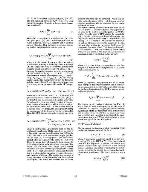
ers, Ng is the number of guard samples, j = fl<strong>and</strong> the sampling period is Tu/N with l/Tu beingsubcarrier spacing. Consider a discrete-time channelcharacterized byK-1h(k) = hlb(k - 71)l=Owhere b(k) represents dirac-delta function, {hl} complexpath gains, (71) path time delays which are assumedin multiple of <strong>OFDM</strong> samples, <strong>and</strong> K the totalnumber of paths. Then the received samples, assumingperfect sampling clock, can be given byK-1r(k) = ezp(j2nkw/~) hls(k - 71 +E) + n(k)l=O(3)where w is the carrier frequency <strong>offset</strong> normalizedto subcarrier spacing, E is <strong>timing</strong> <strong>offset</strong> in units of<strong>OFDM</strong> samples <strong>and</strong> n(k) is the sample of zero meancomplex Gaussian noise process with variance 0:.Suppose the sample indexes of perfectly synchronized<strong>OFDM</strong> symbol be {-Ng, ..., -1, 0, 1, ..., N - 1)<strong>and</strong> maximum channel delay spread be T, . Then ifE E {-Ng +T,~~, -Ng + T + 1,. ~ .. ~ , 0}, the ~ orthogonalityamong the subcarriers will not be destroyed<strong>and</strong> the <strong>timing</strong> <strong>offset</strong> will only introduce a phase rotationin every subcarrier symbol Ym at the FFT outputasY, = e~p(j2~me/N)c,H~+n,, -Ng+rmaZ 5 E < 0(4)where m is subcarrier index, H, is channel frequencyresponse to the mth subchannel, i.e., {Hm} =DFT(h(lc)), <strong>and</strong> nm is complex Gaussian noise term.For coherent system, this phase rotation is compensatedin channel equalization which sees it as a channelintroduced phase shift. If the <strong>timing</strong> estimateis outside the above range, the orthogonality amongthe subcarriers will be destroyed by the resulting ISI.Then the FFT output subcarrier symbols are givenbYcapacity efficiency can be obtained. With this aspect,the per<strong>for</strong>mance of the symbol <strong>timing</strong> synchronizationalgorithms will be evaluated by the <strong>timing</strong>estimator variance.The symbol <strong>timing</strong> estimator finds the start of the<strong>OFDM</strong> symbol. The correct symbol <strong>timing</strong> point willbe taken as the start of the useful part of the <strong>OFDM</strong>symbol (i.e., the start of FFT window <strong>for</strong> demodulation).Let the training symbol (excluding cyclic prefix)contain two identical halves in time domain eachhaving L = N/2 samples. At the receiver there willbe a phase difference between the samples in the firsthalf <strong>and</strong> their replica in the second half caused bythe carrier frequency <strong>offset</strong>. Training data is usuallya PN sequence. Then the Schmidl & Cox's <strong>timing</strong>estimator [14] takes as the start of the symbol themaximum point of the <strong>timing</strong> metric given bywhere d is a time index corresponding to the firstsample in a window of 2L samples <strong>and</strong> Pl(d) is correlationmetric given byL-1Pi(d)= xr*(d+m).r(d+m+L) (7)m=Owhere ()* represents conjugation <strong>and</strong> Rl(d) representsenergy of half <strong>OFDM</strong> symbol <strong>and</strong> is included<strong>for</strong> normalization of the correlation metric in account<strong>for</strong> the large fluctuation of the <strong>OFDM</strong> sample amplitudes<strong>and</strong> given byL-1Rl(d) = (r(d + m + L)12 (8)m=OThe <strong>timing</strong> metric reaches a plateau (see Fig. 2)which leads to some uncertainty as to the start ofthe frame. To alleviate this, [14] proposes an averagingmethod where the maximum point is first found<strong>and</strong> then two points with 90% of the maximum value,one to the left <strong>and</strong> the other to the right of the maximumpoint, are found. The <strong>timing</strong> estimate is takenas the average of the two 90% points.111. Proposed Methodwhere the extra term IE(m) results from IS1 <strong>and</strong> interchannelinterference (ICI) caused by the loss o<strong>for</strong>thogonality among the subcarriers (see [13] <strong>for</strong> details).The useful term also suffers a slight gain lossbut <strong>for</strong> large N, it is negiligible. The main detrimentaleffect is caused by the extra ISI+ICI term.Thus, the guard interval should be long enough <strong>for</strong>the <strong>timing</strong> estimate to lie within the range describedabove. On the other h<strong>and</strong>, longer guard intervaltranslates into more system capacity loss due to overhead.Hence high per<strong>for</strong>mance <strong>timing</strong> synchronizationis much desirable <strong>for</strong> higher system per<strong>for</strong>mance<strong>and</strong> capacity efficiency. The smaller the variance of<strong>timing</strong> estimator is, the shorter the guard interval canbe designed, <strong>and</strong> hence less overhead <strong>and</strong> increasedThe samples of the training symbol (excluding cyclicprefix) are designed to be of the <strong>for</strong>ms=[AA -A -A] (9)where A represents samples of length L = N/4 generatedby N/4 point IFFT of N,/4 length modulateddata of a PN sequence. If desired, the abrupt amplitudechange due to sign conversion in the trainingsymbol can easily be avoided by modifying the PN sequencesuch that the sum of the corresponding modulateddata equals zero. The <strong>timing</strong> metric is givenby0-7803-5718-3/00/$10.00 02000 IEEE. 52VTC2000


