SHURflo Carbonator-Mount Hot Oil NSF Rotary Gear Pumps (Light ...
SHURflo Carbonator-Mount Hot Oil NSF Rotary Gear Pumps (Light ...
SHURflo Carbonator-Mount Hot Oil NSF Rotary Gear Pumps (Light ...

You also want an ePaper? Increase the reach of your titles
YUMPU automatically turns print PDFs into web optimized ePapers that Google loves.
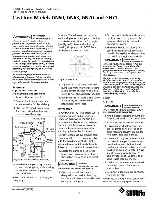
<strong>SHURflo</strong> Operating Instructions, Performance,Specifications and Parts ManualCast Iron Models GN60, GN63, GN70 and GN71Check motor.It may be equippedwith an automatic resetting thermalprotector and may restart unexpectedly(see specifications chart). Protector trippingis an indication of motor overloading as aresult of operating the pump at too high apressure (do not exceed 80 PSI pump orsystem pressure, models with motors arelimited to 40-60 PSI), too high of viscosity,too high of specific gravity, excessively highor low voltage, inadequate wiring, incorrectmotor connections, too small a motor (sizedincorrectly, not enough HP), or a defectivemotor or pump.Do not handle pump with wet hands orwhen standing in water. Failure to followthe General Safety Information and all warningscould result in fatal electrical shock!Assembly(If pump and motor arepre-assembled, skip assembly.)1. Refer to Figures 2 and 3.2. Remove the hex head machinescrew from the ”V“ band clamp.3. Slide the ”V“ band clamp awayfrom the mating face (do notremove from the pump).PumpShaftExt.Ret.Ring“V”Band ClampSeal Seat Assy.Int. Ret. RingHex. HeadClamp ScrewFigure 2 - “V” Band Clamp AssemblyOldhamCouplingMotorShaft4. Match the pump mating face andmotor mounting hub, while matingshafts and Oldham coupling. (Ref.No. 24, Figure 7)NOTE: The small end of coupling goesinto pump.Rotation: When looking at the motorshaft end, proper motor pump rotationis clockwise (CW). Flow is left to right(See Figure 3). Reverse the flow byrotating the pump 180˚. NOTE: Pumpcan be rotated 360° on motor.InFigure 3 - Rotation5. Slip the ”V“ band clamp over thepump and motor halves (See Figure2) and tighten the hex head clampscrew to hold the assembly together.6. Retighten the ”V“band clamp screwas necessary. Use thread sealant ifscrew keeps coming loose.InstallationRotationOutIMPORTANT: In any installations whereproperty damage and/or personalinjury can occur when the pump isnot operating due to power outages,discharge line freezing, or any otherreason, a back-up system(s) and/orwarning system(s) should be used.In order to safely use this product, familiarizeyourself with this pump and alsowith the liquid (chemical, etc.) that isgoing to be pumped through the unit.This pump is not suitable for many liquids.1. Locate the pump as close to theliquid source as possible, makingthe suction line as short and directas possible.Ambienttemperature aroundmotor should not exceed 104˚F (40˚C).2. Open drip-proof motors aredesigned to be used in clean, drylocations with access to an adequatesupply of cooling air.3. For outdoor installations, the motormust be protected by a cover thatdoes not block air flow to andaround the motor.4. The motor should be securely fastenedto a rigid surface, preferablymetallic. For rigidity, use largest boltsthat will fit through the base holes.Do not use topump flammable orexplosive fluids such as gasoline, fuel oil,kerosene, etc. Do not use in flammableand/or explosive atmospheres. Whenpumping hazardous or dangerous materials,use only in room or area designated forthat purpose.For your protection, always wear properclothing, eye protection, etc. in case of anymalfunction. For proper handling techniquesand cautions, contact your chemical supplier,insurance company and local agencies (firedept., etc.). Failure to comply with thiswarning could result in personal injuryand/or property damage.PIPINGSUCTIONOperating pump inreverse directiongreater than 15 PSI will cause seal failure(not covered under warranty).1. Avoid excessive lengths or number offittings and bends in the suction line.2. Attach suction line to suction inlet.3. It is recommended that same sizepipe as pump ports be used or, incases requiring lengthy piping, thenext larger size pipe be used.4. If suction lift is greater than what isindicated in the performance chart,attach a foot valve below liquidlevel at end of suction line to ensurepositive priming. Also note: If fluidspecific gravity is limited to 1.1and/or viscosity of 100 SSU, a footvalve is also recommended.5. If solid contaminates are suspectedin a liquid, place a filter in thesuction line.6. Be certain all suction piping connectionsare airtight.NOTE: Assure airtight pipe connectionswith the use of a pipe joint sealant.Form L-4090 (12/09)5