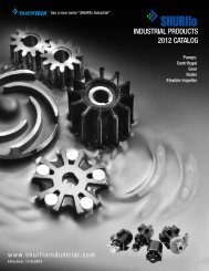
SHURflo Carbonator-Mount Hot Oil NSF Rotary Gear Pumps (Light ...
SHURflo Carbonator-Mount Hot Oil NSF Rotary Gear Pumps (Light ...
SHURflo Carbonator-Mount Hot Oil NSF Rotary Gear Pumps (Light ...

Create successful ePaper yourself
Turn your PDF publications into a flip-book with our unique Google optimized e-Paper software.
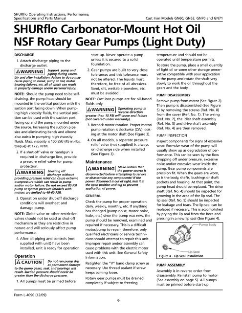
<strong>SHURflo</strong> Operating Instructions, Performance,Specifications and Parts ManualCast Iron Models GN60, GN63, GN70 and GN71<strong>SHURflo</strong> <strong>Carbonator</strong>-<strong>Mount</strong> <strong>Hot</strong> <strong>Oil</strong><strong>NSF</strong> <strong>Rotary</strong> <strong>Gear</strong> <strong>Pumps</strong> (<strong>Light</strong> Duty)DISCHARGE1. Attach discharge piping to thedischarge outlet.Support pump andpiping during assemblyand after installation. Failure to do so maycause piping to break, pump to fail, motorbearing failures, etc. all of which can resultin property damage and/or personal injury.NOTE: Should the pump need to be selfdraining,the pump head should bemounted in the vertical position with thesuction port facing down. When pumpinghigh viscosity fluids, the vertical positioncan be used with the suction portfacing up and the pump mounted underthe source. Increasing the suction pipesize and eliminating bends and elbowsalso assists in pumping high viscosityfluids. Max. viscosity is 100 SSU (45 in.-lbs.torque) at 1725 RPM.2. If a shut-off valve or handgun isrequired in discharge line, providea pressure relief valve for pumpprotection.Shutting offdischarge withoutproviding pressure relief can cause extremeoverpressure which can result in pumpand/or motor failure. Do not exceed 80 PSIpump or system pressure (models withmotors are limited to 40-60 PSI).3. Operation under shut-off dischargeconditions will overheat anddamage pump.NOTE: Globe valve or other restrictivevalves should not be used as shut-offmechanism as they are restrictive innature and will seriously affect pumpperformance.4. After all piping and controls (notsupplied with unit) have beeninstalled, unit is ready for operation.OperationDo not run pump dry,as permanent damageto the pump gears, seal, and bearings willresult. Suction pressure should never begreater than the discharge pressure.1. All pumps must be primed beforestart-up. Never operate a pumpunless it is secured to a solidfoundation.2. <strong>Gear</strong> pumps are built to very closetolerances and this tolerance mustnot be altered. The liquids must,therefore, be free of all abrasives.Sand, silt, wettable powders, etc.must be avoided.NOTE: Cast iron pumps are for oil-basedfluids only.Operating pump inreverse directiongreater than 15 PSI will cause seal failure(not covered under warranty).3. Recheck motor rotation. Proper motor/pump rotation is clockwise (CW) lookingat the motor shaft (See Figure 3).4. On all models, a separate pressurerelief valve (not supplied) is alwayson discharge side when installed(See Figure 3).MaintenanceMake certain thatthe power source isdisconnected before attempting to serviceor disassemble any components! If thepower disconnect is out of sight, lock it inthe open position and tag to preventapplication of power.GENERALCheck the pump for proper operationdaily, weekly, monthly, etc. If anythinghas changed (pump noise, motor noise,leaks, etc.) since the pump was new, thepump should be removed, examined andrepaired if necessary. This is a difficultmotor/pump to repair, therefore, onlyqualified electricians or service techniciansshould attempt to repair this unit.Improper repair and/or assembly cancause problems with the electric motorused with this unit. See General SafetyInformation.Retighten the ”V“ band clamp screw asnecessary. Use thread sealant if screwkeeps coming loose.<strong>Rotary</strong> gear pumps must be drainedcompletely if subject to freezingtemperature and should not beoperated until temperature permits.To store the pump, place a small quantityof light oil or some other storage preservativecompatible with your applicationin the pump and rotate the shaft veryslowly to work the oil throughout thegears and the body.PUMP DISASSEMBLYRemove pump from motor (See Figure 2).Then pump is disassembled (See Figure5) by removing the screws (Ref. No. 8)from the cover (Ref. No. 1). The o-ring(Ref. No. 7), the idler shaft assembly(Ref. No. 3) and drive shaft assembly(Ref. No. 4) are then removed.PUMP INSPECTIONInspect components for signs of excessivewear. Excessive wear of the pump willusually show up as degradation of performance.This can be seen by the flowdropping off under pressure, excessivenoise and/or excessive wear inside thepump. <strong>Gear</strong> pump components areprecision fit. When the gears are worn,so is the body, shafts, bushings or shaftpockets and housing. At that point, thepump head should be replaced. The driveshaft (Ref. No. 4) should be inspected forgrooving in the area of the lip seal. Thelip seal (Ref. No. 5) should be inspectedfor leakage and tears. The lip seal can bereplaced if necessary. This is accomplishedby prying the lip seal from the bore andpressing in a new lip seal (See Figure 4).Figure 4 - Lip Seal InstallationPUMP ASSEMBLYAssembly is in reverse order fromdisassembly. Reinstall pump to motor(See assembly on page 5). All pumpsmust be primed before start-up.Form L-4090 (12/09)6