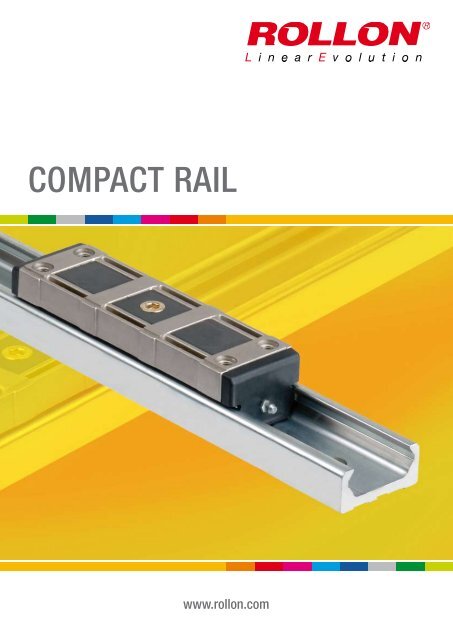
COMPACT RAIL (pdf; EN) - Rollon
COMPACT RAIL (pdf; EN) - Rollon
COMPACT RAIL (pdf; EN) - Rollon
- No tags were found...

You also want an ePaper? Increase the reach of your titles
YUMPU automatically turns print PDFs into web optimized ePapers that Google loves.
<strong>COMPACT</strong> <strong>RAIL</strong>www.rollon.com
About <strong>Rollon</strong>Development of global businessContinual expansion and optimization of the portfolio1975 Parent company, <strong>Rollon</strong> S.r.l., founded in Italy1991 Founding of <strong>Rollon</strong> GmbH in Germany1995 Expansion of headquarters to new 4,000 m 2 factoryAssembly starts in GermanyQuality management certified to ISO 90011998 <strong>Rollon</strong> B.V. in the Netherlands and <strong>Rollon</strong> Corporation in theUSA are foundedExpansion of German branch to new 1,000 m 2 plant1999 Founding of <strong>Rollon</strong> S.A.R.L. in FranceEnvironmental management certified to ISO 140012000 <strong>Rollon</strong> s.r.o. founded in Czech Republic2001 Expansion of headquarters to new 12,000 m 2manufacturing plant2007 Restructuring of the GmbH and alignment of production inGermany to customer-specific adaptationsTakeover of the assets of a manufacturer of linear railsystems2008 Expansion of sales network in Eastern Europe and AsiaFounded in 1975, <strong>Rollon</strong> manufactured high-precision linear roller bearingsfor the machine tool industry. Early on, <strong>Rollon</strong> started manufacturinglinear bearings based on the bearing-cage design. In 1979, the CompactRail self-aligning linear bearings joined the Telescopic Rail industrialdrawer slides and Easy Rail linear bearings and became the basisof the strong foundation on which the company is building upon today.Continuing optimization of these core products still remains one of themost important goals at <strong>Rollon</strong>. The development of the patented CompactRail linear bearing, which uses different proprietary rail profiles and highprecisionradial ball bearing sliders, enables the compensation of heightand angle mounting defects in applications, and is only one example ofthe continuing efforts to innovative the development of our existing productfamilies. In the same manner, we continually introduce innovativenew product familiesdisplaying our continuing product development andoptimization in the industry. These include:■ 1994 Light Rail - full and partial extension telescopic in lightweightdesign■ 1996 Uniline - belt driven linear actuators■ 2001 Ecoline - economical aluminum linear actuators■ 2002 X-Rail - inexpensive formed steel linear guides■ 2004 Curviline - curved monorail profile rail guide with roller carriages■ 2007 Monorail - miniature sizes and full sizedEach further innovation of our linear bearings is built upon the our extensiveknowledge of the nine product families in production today as well ason the current market demands. <strong>Rollon</strong> is the ultimate linear technologyfor any application needs.
Content1 Product explanationStructural shapes and designs2 Technical dataPerformance characteristics and remarksConfigurations and behavior of the sliderunder yawing moment M zLoad capacities3 Product dimensionsRail T, U, KRail TRRail lengthN-version slider, normalN-version slider, longC-version sliderT-rail with N- / C-sliderTR-rail with N- / C-sliderU-rail with N- / C-sliderK-rail with N- / C-slider, Offset of fixing holes4 AccessoriesRollersWipers for C-slider, Alignment fixture AT,Alignment fixture AKFixing screwsManual clamp elements589121618192022242728293032333435
Content5 Technical instructionsLinear accuracyRigiditySupported sides, T+U-system tolerancecompensationK+U-system tolerance compensationPreloadDrive forceStatic loadCalculation formulasService lifeLubrication, N-slider lubricationC-slider lubrication, Corrosion protection,Speed and acceleration, Operating temperatures6 Installation instructionsFixing holesAdjusting the slidersInstalling the single railParallel installation of two railsInstallation of the T+U- or the K+U-systemJoined RailsInstallation of joined rails363842454850525356585960616265676870Ordering keyOrdering key with explanationsPortfolio4 www.rollon.com
1 Product explanationFixed bearing rails ( T-rails)Fixed bearing rails are used as the main load bearing in radial and axialforces.Fig. 2Fixed bearing rails ( TR-rails)The TR rail is also available as a custom design. The TR rail is ground onthe back of the rail and one side surface to allow for a closer mating ontothe surface.Fig. 3Floating bearing rails (U-rails)The floating bearing rails are used for load bearing of radial forces and, incombination with the fixed bearing rail or compensation rail, as a supportbearing for occurring moments.Fig. 4Compensation bearing rails (K-rails)The compensation bearing rails are used for the load bearing of radial andaxial forces. Tolerance compensation in two planes can be implementedin combination with the compensating rail.Fig. 5System (T+U-system)The combination of fixed bearing rail and floating bearing rail allows fordeviations in parallelism.Fig. 6System (K+U-system)The combination of compensation rail and floating bearing rail allows fordeviations in parallelism and height offset.Fig. 76 www.rollon.com
Product explanation 1N-sliderConstructed with a closed, chemically nickel plated aluminum die castbody that is available for sizes 18, 28, 43 and 63. Spring preloaded wipersand a self-lubrication kit are integrated in the end caps (except for size 18,see pg. 58). Configurable with three rollers as standard, in sizes 28 and43 a longer carriage with up to five rollers is also available.Fig. 8CS-sliderConstructed with zinc-plated steel body and sturdy wipers (optional) madeof polyamide. Available for all sizes. Depending on the load case, slider isconfigurable with up to six rollers.Fig. 9CD-sliderConstructed with asymmetrical zinc-plated steel body and sturdy wipers(optional) made of polyamide. With this design the fixing of the movingparts, upward or downward is possible. The Slider is available for sizes 28,35 und 43. Available with three or five rollers, depending on load case andload direction set with the corresponding configuration.Fig. 10RollersAlso available individually in all sizes. Available as eccentric or concentricrollers. Optionally available with splash-proof plastic seal (2RS) or withsteel cover disc (2Z).Fig. 11WipersWipers are available for slider types CS and CD and are made of sturdypolyamide. They keep the raceways free of contamination and thus ensurea longer service life.Fig. 12Alignment fixtureThe alignment fixture AT / AK is used during installation of joined rails forprecise alignment of the rail transition from one to another.Fig. 13www.rollon.com7
2 Technical dataTechnical dataRailSliderRollersFig. 14Performance characteristics:■ Available sizes for T-rail, TR-rail, U-rail: 18, 28, 35, 43, 63■ Available sizes for K-rail: 43, 63■ Max. operating speed: 9 m/s ( 354 in/s)(depending on application)■ Max. acceleration: 20 m/s 2 ( 787 in/s 2 )(depending on application)■ Max. radial load capacity: 15,000 N ( per slider)■ Temperature range: -30 °C to +120 °C (-22 °F to +248 °F )briefly up to max. +170 °C (+338 °F )■ Available rail lengths from 160 mm to 3,600 mm (6.3 in to 142 in)in 80-mm increments (3.15 in),longer single rails up to max. 4,080 mm (160.6 in) on request■ Roller pins lubricated for life■ Roller seal/shield: 2RS (splash-proof), 2Z ( steel cover disk )■ Roller material: steel 100Cr6■ Rail raceways induction hardened and ground■ Rails and slider bodies are standard zinc-plated according toISO 2081■ Rail material of T- and U-rails in sizes 18:cold-drawn roller bearing carbon steel C43 F■ Rail material of K-rails, as well as T- and U-rails in size 28 to 63:CF53Remarks:■ The sliders are equipped with rollers that are in alternating contactwith both sides of the raceway. Markings on the body around theroller pins indicate correct arrangement of the rollers to the externalload■ By a simple adjustment of the eccentric rollers, the slider has clearanceset by the desired preload in the rail■ Rails in joined design are available for longer transverse distances(see pg. 68f)■ The K rails are not suitable for vertical installation■ Screws of property class 10.9 must be used■ Differences in screw sizes must be observed■ During rail installation it must be basically ensured that the fixingholes of the adjacent construction are sufficiently caught hold of (seepg. 60, tab. 41)■ The general illustrations show N-sliders as example8 www.rollon.com
Technical data 2Configurations and behavior of the slider under yawing moment M zIndividual slider under load moment M zWhen an overhanging load in an application with a single slider per railcause an M zmoment in one direction, a 4 to 6 roller Compact Rail slideris available These sliders are available in both configuration A and B inregards to the roller arrangement to counter the acting M zmoment. Themoment capacity of these sliders in the Mz-direction varies significantlythrough spacing L 1und L 2in accordance with the direction of rotation of M z.Especially in the use of two parallel rails, for example with a T+U-system,it is extremely important to pay attention to the correct combination of theslider configuration A and B, in order to use the maximum load capacitiesof the slider.The diagrams below illustrate this concept of the A and B configurationfor sliders with 4 and 6 rollers. The maximum allowable M z-moment isidentical in both directions for all 3 and 5 roller sliders.Slider with 4 rollersConfiguration AM zdM zsFL 1L 2FFFFig. 15Slider with 4 rollersConfiguration BM zdFM zsL 1 L 2FFFFig. 16www.rollon.com9
2 Technical dataTwo sliders under load moment M zIf an overhanging load acts in an application with two sliders per rail andthus causes an M z-moment in one direction, there are differing supportreactions with the two sliders. For this reason, an optimal arrangement ofdifferent slider configurations to reach the maximum load capacities mustbe achieved for the application. In practice this means, when using NTE-,NUE- or CS-sliders with 3 or 5 rollers, both sliders are installed rotatedby 180° so that the slider is always loaded on the side with the mostrollers (with NKE-sliders this is not possible due to the different racewaygeometry). For an even number of rollers this has no effect. The CD-sliderwith installation option from above or below cannot be installed due to theposition of the rollers in reference to the installation side therefore they areavailable in the configurations A and B (see fig. 18).CS-slider under load moment M zFCS-slider with 5 rollersnormal installation directionP1P2CS-slider with 5 rollersinstallation direction rotated by 180°Fig. 17CD-slider under load moment M zFCDW43-120 P1Configuration AP1P2CDW43-120Configuration BFig. 1810 www.rollon.com
Technical data 2Representation of slider arrangement for various load casesArrangement DSThis is the recommended arrangement for use of two sliders under M z-moment when using one rail. Also see previous page: Two sliders underload moment M z.DSFig. 19Arrangement DDFor using pairs of guide rails with two sliders each under load moment M z,the second system should be designed in arrangement DD. This results inthe following combination: Guide rail 1 with two sliders in arrangement DSand guide rail 2 with 2 sliders in arrangement DD. This allows even loadand moment distribution between the two parallel rails.DDFig. 20Arrangement DAStandard arrangement if no other information is given. This arrangementis recommended if the load point is located within the two outside pointsof the sliders.DAFig. 21www.rollon.com11
2 Technical dataLoad capacitiesSliderT-rail U-rail K-railC 0radM yM yC 0axM x M zsM zdC 0radM zsM zdC 0radM zsM zdC 0axThe load capacities in the following tables each apply for one slider.Fig. 22When using the slider in U-rails (compensating bearing rails) the valuesare C 0ax= 0, M x= 0 and M y= 0. When using the sliders in K-rails (compensationrails) the value is: M x= 0.TypeNumberofrollersC[N]C 0rad[N]Load capacities and momentsC 0ax[N]M x[Nm]M y[Nm]M z[Nm]WeightM zdM zs[kg]NT18 3 1530 820 260 1.5 4.7 8.2 8.2 0.03NU18 3 1530 820 0 0 0 8.2 8.2 0.03CS18-060-... 3 1530 820 260 1.5 4.7 8.2 8.2 0.04CS18-080-...-A 4 1530 820 300 2.8 7 8.2 24.7 0.05CS18-080-...-B 4 1530 820 300 2.8 7 24.7 8.2 0.05CS18-100-... 5 1830 975 360 2.8 9.4 24.7 24.7 0.06CS18-120-...-A 6 1830 975 440 3.3 11.8 24.7 41.1 0.07CS18-120-...-B 6 1830 975 440 3.3 11.8 41.1 24.7 0.07Tab. 112 www.rollon.com
Technical data 2TypeNumberofrollersC[N]C 0rad[N]Load capacities and momentsC 0ax[N]M x[Nm]M y[Nm]M z[Nm]WeightM zdM zs[kg]NTE28 3 4260 2170 640 6.2 16 27.2 27.2 0.115NUE28 3 4260 2170 0 0 0 27.2 27.2 0.115NTE28L-3-A 3 4260 2170 640 6.2 29 54.4 54.4 0.141NTE28L-4-A 4 4260 2170 750 11.5 29 54.4 108.5 0.164NTE28L-4-B 4 4260 2170 750 11.5 29 108.5 54.4 0.164NTE28L-4-C 4 4260 2170 750 11.5 29 81.7 81.7 0.164NTE28L-5-A 5 5065 2580 900 11.5 29 81.7 81.7 0.185NTE28L-5-B 5 6816 3472 640 6.2 29 54.4 54.4 0.185NUE28L-3-A 3 4260 2170 0 0 0 54.4 54.4 0.141NUE28L-4-A 4 4260 2170 0 0 0 54.4 108.5 0.164NUE28L-4-B 4 4260 2170 0 0 0 108.5 54.4 0.164NUE28L-4-C 4 4260 2170 0 0 0 81.7 81.7 0.164NUE28L-5-A 5 5065 2580 0 0 0 81.7 81.7 0.185NUE28L-5-B 5 6816 3472 0 0 0 54.4 54.4 0.185CS28-080-... 3 4260 2170 640 6.2 16 27.2 27.2 0.155CS28-100-...-A 4 4260 2170 750 11.5 21.7 27.2 81.7 0.195CS28-100-...-B 4 4260 2170 750 11.5 21.7 81.7 27.2 0.195CS28-125-... 5 5065 2580 900 11.5 29 81.7 81.7 0.24CS28-150-...-A 6 5065 2580 1070 13.7 36.2 81.7 136.1 0.29CS28-150-...-B 6 5065 2580 1070 13.7 36.2 136.1 81.7 0.29CD28-080-... 3 4260 2170 640 6.2 16 27.2 27.2 0.215CD28-125-... 5 5065 2580 900 11.5 29 81.7 81.7 0.3CS35-100-... 3 8040 3510 1060 12.9 33.7 61.5 61.5 0.27CS35-120-...-A 4 8040 3510 1220 23.9 43.3 52.7 158.1 0.33CS35-120-...-B 4 8040 3510 1220 23.9 43.3 158.1 52.7 0.33CS35-150-... 5 9565 4180 1460 23.9 57.7 158.1 158.1 0.41CS35-180-...-A 6 9565 4180 1780 28.5 72.2 158.1 263.4 0.49CS35-180-...-B 6 9565 4180 1780 28.5 72.2 263.4 158.1 0.49CD35-100-... 3 8040 3510 1060 12.9 33.7 61.5 61.5 0.39CD35-150-... 5 9565 4180 1460 23.9 57.7 158.1 158.1 0.58Tab. 2www.rollon.com13
2 Technical dataTypeNumberofrollersC[N]C 0rad[N]Load capacities and momentsC 0ax[N]M x[Nm]M y[Nm]M z[Nm]WeightM zdM zs[kg]NTE43 3 12280 5500 1570 23.6 60 104.5 104.5 0.385NUE43 3 12280 5500 0 0 0 104.5 104.5 0.385NKE43 3 12280 5100 1320 0 50.4 96.9 96.9 0.385NTE43L-3-A 3 12280 5500 1570 23.6 108.6 209 209 0.45NTE43L-4-A 4 12280 5500 1855 43.6 108.6 209 418 0.52NTE43L-4-B 4 12280 5500 1855 43.6 108.6 418 209 0.52NTE43L-4-C 4 12280 5500 1855 43.6 108.6 313.5 313.5 0.52NTE43L-5-A 5 14675 6540 2215 43.6 108.6 313.5 313.5 0.59NTE43L-5-B 5 19650 8800 1570 23.6 108.6 209 209 0.59NUE43L-3-A 3 12280 5500 0 0 0 209 209 0.45NUE43L-4-A 4 12280 5500 0 0 0 209 418 0.52NUE43L-4-B 4 12280 5500 0 0 0 418 209 0.52NUE43L-4-C 4 12280 5500 0 0 0 313.5 313.5 0.52NUE43L-5-A 5 14675 6540 0 0 0 313.5 313.5 0,59NUE43L-5-B 5 19650 8800 0 0 0 209 209 0.59NKE43L-3-A 3 12280 5100 1320 0 97.7 188.7 188.7 0.45NKE43L-4-A 4 12280 5100 1320 0 97.7 188.7 377.3 0.52NKE43L-4-B 4 12280 5100 1320 0 97.7 377.3 188.7 0.52NKE43L-4-C 4 12280 5100 1320 0 97.7 283 283 0.52NKE43L-5-A 5 14675 6065 1570 0 97.7 283 283 0.59NKE43L-5-B 5 19650 8160 1820 0 97.7 188.7 188.7 0.59CS43-120-... 3 12280 5500 1570 23.6 60 104.5 104.5 0.53CS43-150-...-A 4 12280 5500 1855 43.6 81.5 104.5 313.5 0.68CS43-150-...-B 4 12280 5500 1855 43.6 81.5 313.5 104.5 0.68CS43-190-... 5 14675 6540 2215 43.6 108.6 313.5 313.5 0.84CS43-230-...-A 6 14675 6540 2645 52 135.8 313.5 522.5 1.01CS43-230-...-B 6 14675 6540 2645 52 135.8 522.5 313.5 1.01Tab. 314 www.rollon.com
Technical data 2TypeNumberofrollersC[N]C 0rad[N]Load capacities and momentsC 0ax[N]M x[Nm]M y[Nm]M z[Nm]WeightM zdM zs[kg]CSK43-120-... 3 12280 5100 1320 0 50.4 96.9 96.9 0.53CSK43-150-A 4 12280 5100 1320 0 54.3 96.9 290.7 0.68CSK43-150-B 4 12280 5100 1320 0 54.3 290.7 96.9 0.68CSK43-190-... 5 14675 6065 1570 0 108.7 290.7 290.7 0.84CSK43-230-A 6 14675 6065 1570 0 108.7 290.7 484.5 1.01CSK43-230-B 6 14675 6065 1570 0 108.7 484.5 290.7 1.01CD43-120-... 3 12280 5500 1570 23.6 60 104.5 104.5 0.64CD43-190-... 5 14675 6540 2215 43.6 108.6 313.5 313.5 0.95CDK43-120-... 3 12280 5100 1320 0 50.4 96.9 96.9 0.64CDK43-190-... 5 14675 6065 1570 0 108.7 290.7 290.7 0.95NTE63 3 30750 12500 6000 125 271 367 367 1.07NUE63 3 30750 12500 0 0 0 367 367 1.07NKE63 3 30750 11550 5045 0 235 335 335 1.07CS63-180-2ZR 3 30750 12500 6000 125 271 367 367 1.66CS63-235-2ZR-A 4 30750 12500 7200 250 413 367 1100 2.17CS63-235-2ZR-B 4 30750 12500 7200 250 413 1100 367 2.17CS63-290-2ZR 5 36600 15000 8500 250 511 1100 1100 2.67CS63-345-2ZR-A 6 36600 15000 10000 350 689 1100 1830 3.17CS63-345-2ZR-B 6 36600 15000 10000 350 689 1830 1100 3.17CSK63-180-2ZR 3 30750 11550 5045 0 235 335 335 1.66CSK63-235-2ZR-A 4 30750 11550 5045 0 294 335 935 2.17CSK63-235-2ZR-B 4 30750 11550 5045 0 294 935 335 2.17CSK63-290-2ZR 5 36600 13745 6000 0 589 935 935 2.67CSK63-345-2ZR-A 6 36600 13745 6000 0 589 935 1560 3.17CSK63-345-2ZR-B 6 36600 13745 6000 0 589 1560 935 3.17Tab. 4www.rollon.com15
3 Product dimensionsProduct dimensionsRail T, U, KSize 18 - 43T-rail U-rail K-rail (Size 43)BBBTBBBE2E2E 2AAAAAAE1TE1E1TT-43U-43K-43Fig. 23Size 63T-rail U-rail K-railTTTHolesT-63U-63K-63Fig. 24Rail with C-holeRail with V-holettMMMMCCQ¹Q¹V¹V¹Q 1 Fixing holes for Torx ® screws with low head (custom design)included in scope of supplyV 1 Fixing holes for countersunk head screws according to DIN 7991Fig. 2516 www.rollon.com
Product dimensions 3Type Size A[mm]B[mm]M[mm]E 1[mm]T[mm]C[mm]Weight[kg/m]E 2[°]t[mm]Q 1[mm]V 1[mm]TLCTLV18 18 8.25 9 1.5 2.8 9.5 0.55 - 2 M4 M428 28 12.25 14 1 3 11 1.0 - 2 M5 M535 35 16 17.5 2 3.5 14.5 1.65 - 2.7 M6 M643 43 21 21.5 2.5 4.5 18 2.6 - 3.1 M8 M863 63 28 31.5 - 8 15 6.0 2x45 5.2 M8 M10ULCULV18 18 8.25 9 1 2.6 9,5 0.55 - 1.9 M4 M428 28 12 14 1 3 11 1.0 - 2 M5 M535 35 16 17.5 1 3.5 14.5 1.65 - 2.7 M6 M643 43 21 21.5 1 4.5 18 2.6 - 3.1 M8 M863 63 28 31.5 - 8 15 6.0 2x45 5.2 M8 M10KLCKLV43 43 21 21.5 2.5 4.5 18 2.6 - 3.1 M8 M863 63 28 31.5 - 8 15 6.0 2x45 5.2 M8 M10Tab. 5www.rollon.com17
3 Product dimensionsRail TR (ground custom design)Size 18 - 43T-railSize 63T-railHoleBtBMAACQ¹E1TE2TQ 1 Fixing holes for Torx ® screwsT-43with low head (custom design) included in scope of supplyT-63Fig. 26Type Size A[mm]B[mm]M[mm]E 1[mm]T[mm]C[mm]Weight[kg/m]E 2[°]t[mm]Q 1[mm]TRC18 17.95 8 8.95 1.5 2.8 9.5 0.55 - 2 M428 27.83 12.15 13.83 1 2.9 11 1.0 - 2 M535 34.8 15.9 17.3 2 3.4 14.5 1.6 - 2.7 M643 42.75 20.9 21.25 2.5 4.4 18 2.6 - 3.1 M863 62.8 27.9 31.3 - 7.9 15 6.0 2x45 5.2 M8Tab. 618 www.rollon.com
Product dimensions 3Rail length+140 - 2800,240ReferencelineL+ 2- 4Fig. 27Type Size Minlength[mm]Maxlength[mm]Available standard lengths L[mm]TLCTLVULCULV18 160 200028 240 320035 320 360043 400 360063 560 3600160 - 240 - 320 - 400 - 480 - 560 - 640 - 720 - 800 - 880- 960 - 1040 - 1120 - 1200 - 1280 - 1360 - 1440KLCKLV43 400 360063 560 3600- 1520 - 1600 - 1680 - 1760 - 1840 - 1920 - 2000 - 2080- 2160 - 2240 - 2320 - 2400 - 2480 - 2560 - 2640TRCLonger single rails up to max. 4,080 mm on requestLonger rail systems see pg. 68ff Joined rails18 160 200028 240 200035 320 200043 400 200063 560 2000- 2720 - 2800 - 2880 - 2960 - 3040 - 3120 - 3200 - 3280- 3360 - 3440 - 3520 - 3600Tab. 7www.rollon.com19
3 Product dimensionsN-version slider, normalN-seriesSize 18BASlider NTSlider NUBAYXBAFCFCFCX1CCCFFFCCFFYXGGNT18NU18Fig. 28Sizes 28 and 43 (not available in size 35)Slider NTE Slider NUE Slider NKESize 43GGGNTE28/43 NUE28/43 NKE43Fig. 29Size 63Slider NTE Slider NUE Slider NKEYXGGGFig. 3020 www.rollon.com
Product dimensions 3Type Size A[mm]B[mm]C[mm]G[mm]F[mm]X[mm]Y[mm]X 1[mm]No. ofholesRoller type used*Number ofRollersNTNUNT<strong>EN</strong>U<strong>EN</strong>T<strong>EN</strong>UE18 62 74 17.6 6.4 M5 52 5 - 2 CPA18-CPN18 328 88 124 26,5 9.3 M5 78 5 - 2 CPA28-CPN28 343 134 170 40 13.7 M8 114 10 - 2 CPA43-CPN43 3NKE 43 134 170 40 13.7 M8 114 10 - 2 CRA43-CRN43 3NT<strong>EN</strong>UE63 188 225 60 20.2 M8 168 10 34 4 CPA63-CPN63 3NKE 63 188 225 60 20.2 M8 168 10 34 4 CRA63-CRN63 3* Information about the roller type, see pg. 32, tab. 18Tab. 8www.rollon.com21
BACCFFF3 Product dimensionsN-version slider, longN...L-seriesSizes 28 and 43Slider NTE Slider NUE Slider NKESize 43CY X Z XGGGFig. 31Slider configurations N...LN...L-3-AN...L-4-CN...L-4-AN...L-5-AN...L-4-BN...L-5-BFig. 3222 www.rollon.com
Product dimensions 3Type Size A[mm]B[mm]C[mm]G[mm]F[mm]X[mm]Y[mm]Z[mm]No. ofholesRoller typeused*Number**of RollersNTE28LNUE28L28 140 176 26.5 9 M5 52 5 26 4 CPA28NTE43LNUE43L 43 208 245 41 13.7 M8 75.5 10 37 4NKE43L* Information about the roller type, see pg. 32, tab. 18** The number of roller varies according to the configuration, see pg. 22, fig. 32345CPA43 34CRA435Tab. 9www.rollon.com23
3 Product dimensionsC-version sliderCS-seriesBABAYXY X X XConfiguration ABAConfiguration ABAYXY X XConfiguration BBAConfiguration BBAYXY X XRepresentation of slider with wiperFig. 33CS-slider with prismatic rollers for usein T- and U-railsGCSK-slider with crowned rollers foruse in K-railsSizes 43 and 63GCFCFT- und U-Schiene K-SchieneFig. 3424 www.rollon.com
Product dimensions 3Type Size A[mm]B[mm]C[mm]G[mm]F[mm]X[mm]Y[mm]No. ofholesRoller typeused*Number ofRollersCS182835436360 76 9.5 5.7 M5 20 20 2 CPA18-CPN18 380 96 9.5 5.7 M5 40 20 2 CPA18 4100 116 9.5 5.7 M5 20 20 4 CPA18 5120 136 9.5 5.7 M5 40 20 3 CPA18 680 100 14.9 9.7 M5 35 22.5 2 CPA28-CPN28 3100 120 14.9 9.7 M5 50 25 2 CPA28 4125 145 14.9 9.7 M5 25 25 4 CPA28 5150 170 14.9 9.7 M5 50 25 3 CPA28 6100 120 19.9 11.9 M6 45 27.5 2 CPA35-CPN35 3120 140 19.9 11.9 M6 60 30 2 CPA35 4150 170 19.9 11.9 M6 30 30 4 CPA35 5180 200 19.9 11.9 M6 60 30 3 CPA35 6120 140 24.9 14.5 M8 55 32.5 2 CPA43-CPN43 3150 170 24.9 14.5 M8 80 35 2 CPA43 4190 210 24.9 14.5 M8 40 35 4 CPA43 5230 250 24.9 14.5 M8 80 35 3 CPA43 6180 200 39.5 19.5 M8 54 9 4 CPA63 3235 255 39.5 19.5 M8 54 9.5 5 CPA63 4290 310 39.5 19.5 M8 54 10 6 CPA63 5345 365 39.5 19.5 M8 54 10.5 7 CPA63 6CSK4363120 140 24.9 14.5 M8 55 32.5 2 CRA43-CRN43 3150 170 24.9 14.5 M8 80 35 2 CRA43 4190 210 24.9 14.5 M8 40 35 4 CRA43 5230 250 24.9 14.5 M8 80 35 3 CRA43 6180 200 39.5 19.5 M8 54 9 4 CRA63 3235 255 39.5 19.5 M8 54 9.5 5 CRA63 4290 310 39.5 19.5 M8 54 10 6 CRA63 5345 365 39.5 19.5 M8 54 10.5 7 CRA63 6* Information about the roller type, see pg. 32, tab. 18Tab. 10www.rollon.com25
3 Product dimensionsCD-seriesConfiguration ABAConfiguration ABAYXY X X XConfiguration BBAConfiguration BBAYXY X X XRepresentation of slider with wiperFig. 35CD-slider with beveled rollersfor use in T- and U-railsTFTFCDK-slider with crowned Trollersfor use in K-railsSize 43FTFCCCCGGGGHole S for screw Hole S for screw Maccording to DIN according 912 to DIN 912Hole M S for screw Hole S for screw Maccording to DIN according 912 to DIN 912MCD-LäuferCD-LäuferCDR-Läufer CDR-LäuferFig. 36Type Size A[mm]B[mm]C[mm]T[mm]M[mm]SG[mm]FX[mm]Y[mm]No. ofholesRoller typeused*Number ofRollersCD28354380 100 29.9 9.9 4.9 M5 15 M6 36 22 2 CPA28 3125 145 29.9 9.9 4.9 M5 15 M6 27 22 4 CPA28 5100 120 34.9 11.8 5.9 M6 15 M8 45 27.5 2 CPA35 3150 170 34.9 11.8 5.9 M6 15 M8 30 30 4 CPA35 5120 140 44.9 14.8 7.3 M6 15 M8 56 32 2 CPA43 3190 210 44.9 14.8 7.3 M6 15 M8 42 32 4 CPA43 5120 140 44.9 14.8 7.3 M6 15 M8 56 32 2 CRA43 3CDK 43190 210 44.9 14.8 7.3 M6 15 M8 42 32 4 CRA43 5Tab. 11* Information about the roller type, see pg. 32, tab. 1826 www.rollon.com
Product dimensions 3T-rail with N- / C-sliderT-rail with N-sliderT-rail with CS-sliderT-rail with CD-sliderDACDACACDReferencelineBReferencelineBReferencelineBFig. 37Configuration Size A[mm]B[mm]C[mm]D[mm]TL... / NT 18 18+0.25-0.1016.5+0.15-0.1517.60-0.2018.3+0.25-0.2528 28+0.25-0.1024+0.25-0.1026.5+0.10-0.2028+0.15-0.35TL... / NTE43 43+0.35-0.1037+0.25-0.10400-0.3041.9+0,20-0.3563 63+0.35-0.1050.5+0.25-0.1060+0.10-0.20620-0.50TL... / NTE...L28 2843 43+0.25-0.10+0.35-0.102437+0.25-0.10+0.25-0.1026.541+0.10-0.200-0.302842.4+0.15-0.35+0.20-0.3518 18+0.25-0.1015+0.15-0.159.50-0.0514+0.05-0.2528 28+0.25-0.1023.9+0.15-0.1514.90-0.1021.7+0.05-0.35TL... / CS35 35+0.35-0.1030.2+0.10-0.3019.9+0.05-0.1527.85+0.10-0.3043 43+0.35-0.1037+0.15-0.1524.90-0.1534.3+0.10-0.3063 63+0.35-0.1049.8+0.15-0.1539.5+0.15051.6+0.15-0.3028 28+0.25-0.1024.1+0.20-0.2029.90-0.5032+0.05-0.35TL... / CD35 35+0.35-0.1030.1+0.20-0.2034.90-0.5037.85+0.10-0.3043 43+0.35-0.1037.3+0.20-0.2044.90-0.5047+0.10-0.30Tab. 12www.rollon.com27
3 Product dimensionsTR-rail with N- / C-sliderTR-rail with N-sliderTR-rail with CS-sliderTR-rail with CD-sliderDACDACACDReferencelineBReferencelineBReferencelineBFig. 38Configuration Size A[mm]B[mm]C[mm]D[mm]TR... / NT 18 17.95+0.10-0.0516.4+0.10-0.0517.60-0.2017.9+0.15-0.1528 27.83+0.10-0.0523.9+0.15-0.1026.5+0.10-0.2027.2+0.15-0.15TR... / NTE43 42.75+0.10-0.0536.9+0.15-0.10400-0.3041.3+0.15-0.2063 62.8+0.10-0.0550.4+0.20-0.1060+0,10-0.3061.3+0.15-0.20TR... / NTE...L28 27.8343 42.75+0.10-0.05+0.10-0.0523.936.9+0.15-0.10+0.15-0.1026.541+0.10-0.200-0.3027.241.8+0.15-0.15+0.15-0.2018 17.95+0.10-0.0514.9+0.10-0.109.50-0.0513.8+0.15-0.1528 27.83+0.10-0.0523.8+0.10-0.1014.90-0.1021.3+0.10-0.20TR... / CS35 34.75+0.10-0.0530.1+0.10-0.3019.9+0,05-0.1527.35+0.10-0.2043 42.75+0.10-0.0536.9+0.15-0.1024.90-0.1533.5+0.10-0.2063 62.8+0.10-0.0549.7+0.10-0.1539.5+0.15051.05+0.15-0.1028 27.83+0.10-0.0524+0.10-0.2029.90-0.5031.63+0.10-0.20TR... / CD35 34.75+0.10-0.0530+0.10-0.2034.90-0.5037.35+0.10-0.2043 42.75+0.10-0.0537.2+0.10-0.2044.90-0.5046.4+0.10-0.20Tab. 1328 www.rollon.com
Product dimensions 3U-rail with N- / C-sliderU-rail with N-sliderU-rail with CS-sliderU-rail with CD-sliderDACDACACDReferencelineBReferencelineBReferencelineBFig. 39Configuration Size A[mm]B nom*[mm]C[mm]D[mm]UL... / NU 18 18+0.25-0.1016.5 17.60-0.2018.3+0.25-0.2528 28+0.25-0.1024 26.50-0.2028+0.15-0.35UL... / NUE43 43+0.35-0.1037 400-0.3041.9+0.20-0.3063 63+0.35-0.1050.5 60 -0.20 620-0.50UL... / NUE...L28 2843 43+0.25-0.10+0.35-0.1024 26.537 410-0.200-0.302842.4+0.15-0.35+0.20-0.3518 18+0.25-0.1015 9.50-0.0514+0.05-0.2528 28+0.25-0.1023.9 14.90-0.1021.7+0.05-0.35UL... / CS35 35+0.35-0.1030.2 19.9+0.05-0.1527.85+0.10-0.3043 43+0.35-0.1037 24.90-0.1534.3+0.15-0.3063 63+0.35-0.1049.8 39.5+0.15051.6+0.15-0.3028 28+0.25-0.1024.1 29.90-0.5032+0.05-0.35UL... / CD35 35+0.35-0.1030.1 34.90-0.5037.85+0.10-0.3043 43+0.35-0.1037.3 44.90-0.5047+0.10-0.30* see pg. 43 Offset T+U-systemsee pg. 46 Offset K+U-systemTab. 14www.rollon.com29
3 Product dimensionsK-rail with N- / C-sliderK-rail with N-sliderK-rail with CS-sliderK-rail with CD-sliderDACDACACDReferencelineBReferencelineBReferencelineBThe K-rail enables the slider a rotation around its longitudinal axis (see pg. 45f)Fig. 40Configuration Size A[mm]B[mm]C[mm]D[mm]KL... / NKE43 4363 63+0.35-0.10+0.35-0.103750.5+0.25-0.10+0.25-0.1040600-0.30+0.10-0.2041.962+0.20-0.350-0.50KL... / NKE...L 43 43+0.35-0.1037+0.25-0.10410-0.3042.7+0.20-0.35KL... / CSK43 4363 63+0.35-0.10+0.35-0.103749.8+0.15-0.15+0.15-0.1524.939.50-0.15+0.15034.351.6+0.10-0.30+0.15-0.30KL... / CDK 43 43+0.35-0.1037.3+0.20-0.2044.90-0.5047+0.10-0.30Tab. 15Offset of fixing holesPrinciple representation of offset with T-railsδδReference lineBezugslinieBezugslinieReference line30 www.rollon.comFig. 41
Product dimensions 3Sizeδ nominal[mm]δ maximum[mm]δ minimum[mm]ConfigurationConfigurationSizeδ nominal[mm]δ maximum[mm]δ minimum[mm]TLC / NT 18 0.45 0.95 -0.2528 0.35 0.85 -0.418 0.3 0.7 -0.228 0.3 0.6 -0.3TLC / NTE43 0.35 0.9 -0.5ULC / CS35 0.35 0.7 -0.3563 0.35 0.8 -0.5543 0.4 0.75 -0.3563 0.35 0.6 -0.25KLC / NKE43 0.35 0.9 -0.563 0.35 0.8 -0.5518 0.35 0.6 -0.1528 0.25 0.45 -0.3ULC / NU 18 0.4 0.9 -0.2528 0.4 0.85 -0.3TLV / CS35 0.35 0.55 -0.343 0.35 0.65 -0.3ULC / NUE43 0.4 0.85 -0.4563 0.35 0.8 -0.4563 0.35 0.45 -0.35TLV / NT 18 0.45 0.8 -0.228 0.35 0.7 -0.35KLV / CSK43 0.35 0.65 -0.363 0.35 0.45 -0.35TLV / NTE43 0.35 0.75 -0.4563 0.35 0.65 -0.5518 0.3 0.55 -0.1528 0.3 0.45 -0.25ULV / CS35 0.35 0.55 -0.3KLV / NKE43 0.35 0.75 -0.4563 0.35 0.65 -0.5543 0.4 0.6 -0.363 0.35 0.45 -0.25ULV / NU 18 0.4 0.75 -0.228 0.4 0.7 -0.25TRC / NT 18 0.15 0.65 -0.228 0.15 -0.5 -0.25ULV / NUE43 0.4 0.7 -0.4TRC / NTE43 0.05 0.4 -0.363 0.35 0.65 -0.4563 0 0.4 -0.418 0.35 0.75 -0.218 0.05 0.45 -0.228 0.25 0.6 -0.3528 0.05 0.3 -0.25TLC / CS35 0.35 0.7 -0.35TRC / CS35 0.1 0.35 -0.243 0.35 0.8 -0.3543 0.05 0.35 -0.2563 0.35 0.6 -0.3563 0 0.2 -0.2Tab. 17KLC / CSK43 0.35 0.8 -0.3563 0.35 0.6 -0.35Tab. 16www.rollon.com31
4 AccessoriesAccessoriesRollersVersion 1Prismatic (T- and U-rail)GGVersion 2Crowned (K-rail)GGCPNConcentric rollerAAFDFDCRNConcentric rollerAAFDFDCPAEccentric rollerEccentricityEccentricityBHBHKKCRAEccentric rollerEccentricityEccentricityBHBHKKSeals: 2RS is the splash-proof seal, 2Z (2ZR for size 63) is the steel cover discNote: The rollers are lubricated for lifeCPN/CPA CPN/CPACRN/CRA CRN/CRAFig. 42TypeA[mm]B[mm]D[mm]e[mm]H[mm]K[mm]G[mm]FC[N]C 0rad[N]Weight[kg]CPN18-2RS 14 4 6 - 1.55 1.8 5.5 M4 765 410 0.004CPN18-2Z 14 4 6 - 1.55 1.8 5.5 M4 765 410 0.004CPA18-2RS 14 4 6 0.4 1.55 1.8 5.5 M4 765 410 0.004CPA18-2Z 14 4 6 0.4 1.55 1.8 5.5 M4 765 410 0.004CPN28-2RS 23.2 7 10 - 2.2 3.8 7 M5 2130 1085 0.019CPN28-2Z 23.2 7 10 - 2.2 3.8 7 M5 2130 1085 0.019CPA28-2RS 23.2 7 10 0.6 2.2 3.8 7 M5 2130 1085 0.019CPA28-2Z 23.2 7 10 0.6 2.2 3.8 7 M5 2130 1085 0.019CPN35-2RS 28.2 7.5 12 - 2.55 4.2 9 M5 4020 1755 0.032CPN35-2Z 28.2 7.5 12 - 2.55 4.2 9 M5 4020 1755 0.032CPA35-2RS 28.2 7.5 12 0.7 2.55 4.2 9 M5 4020 1755 0.032CPA35-2Z 28.2 7.5 12 0.7 2.55 4.2 9 M5 4020 1755 0.032CPN43-2RS 35 11 12 - 2.5 4.5 12 M6 6140 2750 0.06CPN43-2Z 35 11 12 - 2.5 4.5 12 M6 6140 2750 0.06CPA43-2RS 35 11 12 0.8 2.5 4.5 12 M6 6140 2750 0.06CPA43-2Z 35 11 12 0.8 2.5 4.5 12 M6 6140 2750 0.06CPN63-2ZR 50 17.5 18 - 2.3 6 16 M8 15375 6250 0.19CPA63-2ZR 50 17.5 18 1.2 2.3 6 16 M10 15375 6250 0.19CRN43-2Z 35.6 11 12 - 2.5 4.5 12 M6 6140 2550 0.06CRA43-2Z 35.6 11 12 0.8 2.5 4.5 12 M6 6140 2550 0.06CRN63-2ZR 49.7 17.5 18 - 2.3 6 16 M8 15375 5775 0.19CRA63-2ZR 49.7 17.5 18 1.2 2.3 6 16 M10 15375 5775 0.19Tab. 1832 www.rollon.com
Accessories 4Wipers for C-sliderWiper WT for T-rail Wiper WU for U-rail Wiper WK for K-railAbstreifer T-SchieneSizes 43 and 63Abstreifer T-SchieneAbstreifer K-SchieneAbstreifer T-SchieneAbstreifer U-SchieneAbstreifer K-SchieneFig. 43Abstreifer U-SchieneAbstreifer K-SchieneAlignment fixture AT (for T- and U-rail)Abstreifer U-SchieneRail sizeAlignment fixture18 AT 1828 AT 2835 AT 3543 AT 4363 AT 63Tab. 19Fig. 44Alignment fixture AK (for K-rail)Rail sizeAlignment fixture43 AK 4363 AK 63Tab. 20Fig. 45www.rollon.com33
4 AccessoriesFixing screwsLKRailsizedUsable threadlengthD L K[mm] [mm] [mm]STighteningtorque[Nm]18 M4 x 0.7 8 8 2 T20 3SdD28 M5 x 0.8 10 10 2 T25 935 M6 x 1 13 13 2,7 T30 1243 M8 x 1.25 16Screw type 3 T40 22Fig. 4663 M8 x 1.25 13 20 5 T40 35Tab. 21Usable threadlengthRail size Screw type Usable threadlengthK[mm]18 M4 x 8 7.2D28 M5 x 10 9Screw type35 M6 x 13 12.243 M8 x 16 14.6Fig. 4763 M8 x 20 17.2Tab. 2234 www.rollon.com
Accessories 4Manual clamp elementsCompact Rail guides can be secured with manual clamping elements.Areas of application are:■ Table cross beams and sliding beds■ Width adjustment, stops■ Positioning of optical equipment and measuring tablesThe HK series is a manually activated clamping element. By using the freelyadjustable clamping lever (except for HK 18, which uses hexagonWsocketg 1bolt M6 DIN 913 with 3 mm drive) press the contact profile synchronouslyon the free surfaces fo the rail. The floating mounted contact profiles guaranteesymmetrical introduction of force on the guide rail.H 2HH 1HK 18g 1WMLHWH 2H 2HH 1LHK 28-63 (except for size 35)Mg 1H 1H 3Fig. 48Hg 1WH 1H 3LP 1P 2M (4 threads)H 2W 1W 2P 2M (4 threads)Fig. 49LP 1Type Size Holdingforce[N]Tighteningtorque[Nm]DimensionsW 1[mm]W 2H H 1H 2H 3W W 1W 2L P 1P 2g 1HK1808A 18 150 0.5 15 3.2 3 - 35 - - 43 0 0 6 M5HK2808A 28 1200 7 24 17 5 64 68 38.5 41.5 24 15 15 6 M5HK4308A 43 2000 15 37 28.5 8 78 105 46.5 50.5 39 22 22 12 M8HK6308A 63 2000 15 50.5 35 9.5 80 138 54.5 59.5 44 26 26 12 M8Tab. 23Mwww.rollon.com35
5 Technical instructionsTechnical instructionsLinear accuracyLinear accuracy is defined as the maximum deviation of the slider in the railbased on the side and support surface during straight line movement.The linear accuracy, depicted in the graphs below, applies to rails thatare carefully installed with all the provided screws on a level and rigidfoundation.160140120100TRC...-Lµm8060TL...-UL...-KL...402000 500 1000 1500 2000 2500 3000 3500Length [mm]S120100µm80604020TRCTL...-KL...S00 500 1000 1500 2000 2500 3000 3500Length [mm]Fig. 5036 www.rollon.com
Technical instructions 5Deviation of accuracy with two 3 roller sliders in one railTypeTL..., UL..., KL...TRCΔL [mm]Slider with equal arrangement0.2ΔL [mm]Slider with opposite arrangement1.0ΔS [mm] 0.05Tab. 24www.rollon.com37
5 Technical instructionsRigidityTotal deformationIn the following deformation diagrams the total deviation of the linear guideis indicated under the effect of external loads P or moments M.As seen from the graphs, the rigidity can be increased by supporting thesides of the rails. The graph values indicate only the deformation of thelinear guide, the supporting structure is assumed infinitely rigid. All graphsrefer to sliders with 3 rollers and K1 preload (standard setting). An increasedpreload, K2, reduces the deformation values by 25 %.Size 18 - 43Radial load400350P300250δδ [µm]200150182835431005000 500 1000 1500 2000 2500 3000 3500 4000 4500 5000 5500P [N]250200P150δδ [μm]100182835435000 500 1000 1500 2000 2500 3000 3500 4000 4500 5000 5500P [N]Fig. 5138 www.rollon.com
Technical instructions 5Axial load140P120δ100δ [μm]806040182835432000 200 400 600 800 1000 1200 1400 1600P [N]Moment Mx1412Mx10δδ [mrad]86182835434200 2 4 6 8 10 12 14 16 18 20 22 24Mx [Nm]Fig. 52www.rollon.com39
5 Technical instructionsSize 63Radial load450P400δ [μm]350300250200NT/NU63CS63δ1501005000 2000 4000 6000 8000 10000 12000 14000P [N]350P300250δ [μm]200150NT/NU63CS63δ1005000 2000 4000 6000 8000 10000 12000 14000P [N]Fig. 5340 www.rollon.com
Technical instructions 5Axial loadδP200180160140120δ [μm]10080604020NT63CS6300 1000 2000 3000 4000 5000 6000 7000P [N]Moment Mx18Mxδ161412δ [mrad]1086NT63CS634200 25 50 75 100 125 150Mx [Nm]Fig. 54www.rollon.com41
5 Technical instructionsSupported sidesIf a higher system rigidity is required, a support of the rail sides is recommended,which can also be used as the reference surface (see fig. 55).The minimum required support depth can be taken from the adjacenttable (see tab. 25).Rail sizeA[mm]B[mm]18 5 428 8 435 11 543 14 563 18 5Tab. 25Fig. 55T+U-system tolerance compensationAxial deviations in parallelismThis problem occurs fundamentally by insufficient precision in the axialparallelism of the mounting surfaces, which results in an excessive loadon the slider and thus causes drastically reduced service life.The use of fixed bearing and compensating bearing rail ( T+U-system)solves the unique problem of aligning two track, parallel guide systems.By using a T+U-system, the T-rail takes over the motion of the track whilethe U-rail serves as a support bearing and takes only radial forces and M zmoments.Fig. 5642 www.rollon.com
Technical instructions 5T+U-system maximum offsetU-rails have flat parallel raceways that allow free lateral movement of thesliders. The maximum axial offset that can be compensated for in eachslider of the U-rail is made up of the combined values S 1and S 2listed intable 26. Considered from a nominal value B nomas the starting point, S 1indicates the maximum offset into the rail, while S 2represents the maximumoffset towards the outside of the rail.Bmin.-S1Bnom.Bmax.+S 2Fig. 57Slider type S 1[mm]S 2[mm]B min[mm]B nom[mm]B max[mm]NU18 0 1.1 16.5 16.5 17.6CS18 0.3 1.1 14.7 15 16.1NUE28NUE28LCS28CD280 1.3 24 24 25.30.6 1.3 23.3 23.9 25.2CS35 1.3 2.7 28.9 30.2 32.9CD35 1.3 2.7 28.8 30.1 32.8NUE43NUE43L0 2.5 37 37 39.5CS43 1.4 2.5 35.6 37 39.5CD43 1.4 2.5 35.9 37.3 39.8NUE63 0 3.5 50.5 50.5 54CS63 0.4 3.5 49.4 49.8 53.3Tab. 26www.rollon.com43
5 Technical instructionsThe application example in the adjacent drawing (see fig. 59) shows thatthe T+U-system implements a problem-free function of the slider evenwith an angled offset in the mounting surfaces.If the length of the guide rails is known, the maximum allowable angledeviation of the screwed surfaces can be determined using this formula(the slider in the U-rail moves here from the innermost position S 1to outermostposition S 2):αα = arctan S*LS* = Sum of S 1and S 2L = Length of railSFig. 58The following table (tab. 27) contains guidelines for this maximum angledeviation α, achievable with the longest guide rail from one piece.LSizeRail length[mm]Offset S[mm]Angle α[°]18 2000 1.4 0.04028 3200 1.9 0.03435 3600 4 0.063Fig. 5943 3600 3.9 0.06263 3600 3.9 0.062Tab. 27The T+U-system can be designed in different arrangements (see fig. 60).A T-rail accepts the vertical components of load P. A U-rail attached underneaththe component to be guided prevents the vertical panel fromswinging and is used as moment support. In addition a vertical offsetin the structure, as well as possible existing unevenness of the supportsurface, is compensated for.Fig. 6044 www.rollon.com
Technical instructions 5K+U-system tolerance compensationDeviations in parallelism in two planesThe K+U-system, like the T+U-system, can compensate for axial deviationsin parallelism. Additionally, the K+U system has the option of rotatingthe slider in the rail, which will compensate for other deviations inparallelism, e.g. height offset.The unique raceway contour of the K-rail allows the slider a certain rotationaround its longitudinal axis, with the same linear precision as witha T-rail. With the use of a K+U-system, the K-rail accounts for the mainloads and the motion of the track. The U-rail is used as a support bearingand takes only radial forces and M zmoments. The K-rail must always beinstalled so that the radial load of the slider is always supported by at least2 load bearing roller sliders, which lie on the V-shaped raceway (referenceline) of the rail.Fig. 61K-rails and sliders are available in both sizes 43 and 63.The custom NKE-slider may only be used in K-rails and cannot be exchangedwith other <strong>Rollon</strong> sliders. The maximum allowable rotation angleof the NKE- and NUE-sliders are shown in the following table 28 and figure62. α 1is the maximum rotation angle counterclockwise, α 2is clockwise.Slider type α 1[°]NKE43 and NUE43 2 2α 2[°]NKE63 and NUE63 1 1Tab. 28ααα 1α 1α2α2NKE43NUE43NK<strong>EN</strong>K<strong>EN</strong>K<strong>EN</strong>KEFig. 62www.rollon.com45
5 Technical instructionsK+U-system maximum offsetIt must be noted that the slider in the U-rail will turn during the movementand rotation of the slider in the K-rail to allow an axial offset. During thecombined effect of these movements, you must not exceed the maximumvalues (see tab. 29). If a maximum rotated NUE- slider is observed (2°for size 43 and 1° for size 63), the maximum and minimum position ofthe slider in the U rail results from the values B 0maxand B 0min, which arealready considered by the additional rotation caused axial offset. B 0nomisa recommended nominal starting value for the position of a NUE-slider inthe U-rail of a K+U-system.B0min B0nom B0maxFig. 63Slider typeB 0min[mm]B 0nom[mm]B 0max[mm]NUE43NUE43L37.6 38.85 40.1CS43 37.6 38.85 40.1CD43 37.9 39.15 40.4NUE63 50.95 52.70 54.45CS63 49.85 51.80 53.75Tab. 2946 www.rollon.com
NKE43NUE43Technical instructions 5If a K-rail is used in combination with a U-rail, with guaranteed problemfreerunning and without extreme slider load, a pronounced height differencebetween the two rails can also be compensated for. The followingillustration shows the maximum height offset b of the mounting surfacesin relation to the distance a of the rails (see fig. 64).bab - maximum height offset (mm )1007550250-25-50-75-100Size 43Size 630 250 500 750 1000 1250 1500 1750 2000 2250 2500a - distance between the rails (mm )Fig. 64Even the K+U-system can be used in different arrangements. If the sameexample as with the T+U-system is observed (see pg. 44, fig. 60), thissolution, in addition to the prevention of vibrations and moments, alsoenables the compensation of larger deviations in parallelism in the verticaldirection, without negative consequences to the guide. This is particularlyimportant for longer strokes as it is more difficult to obtain a correct verticalparallelism.Fig. 65www.rollon.com47
5 Technical instructionsPreloadPreload classesThe factory installed systems, consisting of rails and sliders, are availablein two preload classes:Standard preload K1 means a rail-slider combination with minimum preloadwhich means the rollers are adjusted free of clearance for optimalrunning properties.Usually preload K2 is used for rail-slider systems for increasing the rigidity(see pg. 38ff). When using a system with K2 preload a reduction of theloading capacities and service life must be taken into consideration (seetab. 30).Preload classReduction yK1 -K2 0.1Tab. 30This coefficient y is used in the calculation formula for checking the staticload and lifetime (see pg. 52, fig. 75 and pg. 56, fig. 92).The excess is the difference between the contact lines of the rollers andthe raceways of the rail.Preload classExcess*[mm]Rail typeK1 0.01 allK20.03 T, U...180.04 T, U...280.05 T, U...350.06* Measured on the largest interior dimension between the racewaysT, U, K...43,T, U, K...63Tab. 3148 www.rollon.com
Technical instructions 5External preloadThe unique design of the Compact Rail product family enables applying apartial external preload on selected locations along the entire guide.An external preload can be applied by pressure along the side surfacesof the guide rail according to the drawing below (see fig. 66). This localpreload results in higher rigidity only at the locations where it is necessary(e.g. on reversing points with high dynamic auxiliary forces).This partial preload increases the service life of the linear guide by avoidinga continually increased preload over the entire length of the guide.Also the required drive force of the linear carriage in the non-preloadedareas is reduced.The amount of the externally applied preload is determined using two dialindicators by measuring the deformation of the rail sides. These are deformedby thrust blocks with pressure screws. The external preload must beapplied when the slider is not directly located in the pressure zone.SizeA[mm]18 4028 5535 7543 8063 120Tab. 32Dial indicator for determining the side deformationFig. 66The graph below indicates the value of the equivalent load as a functionof the total deformation of both rail sides. The data relates to sliders withthree rollers (see fig. 67).Equivalent load [%C 0rad]A minimumPressure screwsThrust blockδ [μm]Fig. 67www.rollon.com49
5 Technical instructionsDrive forceFrictional resistanceThe drive force required for moving the slider is determined by the combinedresistance of the rollers, wipers and seals.The surface machining of the raceways and rollers have a minimal coefficientof friction, which remains almost the same in both the static anddynamic state. The wiper and longitudinal seals are designed for an optimumprotection of the system, without a significant negative influence onthe quality of motion. The overall friction of the Compact Rail also dependsfrom external factors such as lubrication, preload and additional forces.Table 33 below contains the coefficients of friction for each slider type (forCSW and CDW sliders no friction occurs to μ s).Fig. 68Size µ Roller friction µ wWiper friction µ sFriction of longitudinal sealsIn ( m · 1000 )*18 0.003 0.00150.98 · m · 100028 0.00335 0.00543 0.005In ( m · 1000 )*0.06 · m · 1000In ( m · 1000 )*0.15 · m · 100063 0.006* Kilograms must be used for load mTab. 33The values given in Table 33 apply to external loads, which, with sliderswith three rollers, are at least 10 % of the maximum load rating. For calculatingthe driving force for lower loads, please contact our ApplicationEngineering Department.Calculation of drive forceThe minimum required drive force for the slider is determined with thecoefficients of friction (see pg. 50, tab. 33) and the following formula (seefig. 69):Example calculation:If a NTE43 slider is used with a radial load of 100 kg, the result isμ = 0.005; from the formula the following is calculated:In (100000)µ s= = 0.000760.15 · 100000In (100000)µ w= = 0.00190.06 · 100000F = ( µ + µ w+ µ s) · m · gm = mass (kg)g = 9.81 m/s 2Fig. 69This is the minimum drive force for this example:Fig. 70F = ( 0.005 + 0.0019 + 0.00076 ) · 100 · 9.81 = 7.51 NFig. 7150 www.rollon.com
Technical instructions 5Roller friction µ0,02250,02000,01750,01500,01250,01000,00750,00500,002500 0,025 0,050 0,075 0,100 0,125 0,150 0,175 0,200 0,225 0,250 0,275 0,300Duty factor P/C 0Size 18Roller friction µ0,110,100,090,080,070,060,050,040,030,020,010Size 28Size 35Size 430 0,02 0,04 0,06 0,08 0,10factor P/C0,12 0,14 0,16 0,18 0,20Roller friction µ0,120,110,100,090,080,070,060,050,040,030,020,010Size 630 0,01 0,02 0,03 0,04 0,05 0,06 0,07 0,08 0,09 0,10Duty factor P/C 0Fig. 72www.rollon.com51
5 Technical instructionsStatic loadThe radial load capacity rating, C 0radthe axial load capacity rating C 0ax, andmoments M x, M y, M zindicate the maximum permissible values of the load(see pg. 12ff), higher loads will have a detrimental effect on the runningquality. A safety factor, S 0, is used to check the static load, which takesinto account the basic parameters of the application and is defined morein detail in the following table:Safety factor S 0Fig. 73No shock nor vibration, smooth and low-frequency reverse,high assembly accuracy, no elastic deformations1 - 1.5Normal installation conditions 1.5 - 2Shock and vibration, high-frequency reverse, significant elastic deformation 2 - 3.5The ratio of the actual load to maximum permissible load may be as largeas the reciprocal of the accepted safety factor, S 0, at the most.P 0rad1≤P 0ax1≤M 11≤M 21≤M 31≤C 0radS 0C 0axS 0M xS 0M yS 0M zS 0Fig. 74The above formulas are valid for a single load case.If two or more forces are acting simultaneously, please check the followingformula:P 0radP 0axM 1M 2M+ + + +3+ y ≤ 1 C 0radC 0axM xM yM zS 0P 0radC 0radP 0axC 0ax= effective radial load (N)= permissible radial load (N)= effective axial load (N)= permissible axial load (N)M 1, M 2, M 3= external moments ( Nm)M x, M y, M z= maximum permissible momentsin the different loading directions (Nm)y = reduction due to preloadFig. 75The safety factor S 0can lie on the lower given limit if the occurring forcescan be determined with sufficient precision. If shock and vibration arepresent, the higher value should be selected. For dynamic applicationshigher safety is required. Please contact the Application Engineering Department.52 www.rollon.com
Technical instructions 5Calculation formulasExamples of formulas for determining the forces on the most heavily loaded sliderFor an explanation of the parameters in the formulas see pg. 55, fig. 90Slider load:Horizontal movementStatic testP1FP2P 1= F ·ba+bP 2= F - P 1M1cin addition each slider isloaded by a moment:FaFbM 1=F2· cFig. 76Fig. 77Slider load:Horizontal movementStatic testP 1a≅ P 2a=F2P2aP2bP 2b≅ P 1b= F ·abFbFFig. 79P1aP1baFig. 78Slider load:Horizontal movementStatic testP 2= F ·abP 1= P 2+ FbaFFFig. 81P2P1Note: Applies only if the distance between centers of the sliders b > 2xslider lengthFig. 80www.rollon.com53
5 Technical instructionsSlider load:Horizontal movementStatic testFF F b F aP 1= - ( · ) - ( · )4 2 c 2 dP1-2bP3-4F F b F aP 2= - ( · ) + ( · )4 2 c 2 ddP1P3F F b F aP 3= + ( · ) - ( · )4 2 c 2 dP2cP4aF F b F aP 4= + ( · ) + ( · )4 2 c 2 dFig. 82Fig. 83Note: It is defined that slider no. 4 is always located closest to the pointwhere the force is applied.bP2Vertical movementStatic testP2Slider load:P 1≅ P 2= F ·abP1FbFig. 85P1FNote: Applies only if the distance between centers of the sliders b > 2xslider lengthaaFig. 84Slider load:Horizontal movementStatic testaP 1= FM2FP1M 2= F · aFig. 87Fig. 8654 www.rollon.com
llTechnical instructions 5Center Center of gravity of of gravity ofthe moving the moving element elementFFF gF gF gF gP1P1P2P2ddDriveDriveDirection DirectionFig. 88Horizontal movementTest with a moving element of the weight-force F gat the instant the directionof movement changesvvInertial forceF = m · aSlider load at time tof reversett1 t1 2 2ttF · IP 1= +dF g2F gP 2= -2F · IdFig. 89Explanation of the calculation formulaF = effective force (N)F g= weight-force (N)P 1, P 2, P 3, P 4= effective load on the slider (N)M 1, M 2= effective moment (Nm)m = mass (kg)a = acceleration (m/s²)Fig. 90www.rollon.com55
5 Technical instructionsService lifeThe dynamic load capacity C is a conventional variable used for calculatingthe service life. This load corresponds to a nominal service life of 100 km.For values of the individual slider see pg. 12ff Load capacities. The followingformula (see fig. 91) links the calculated theoretical service life to thedynamic load capacity and the equivalent load:L km= theoretical service life ( km )C = dynamic load capacity ( N )C fL Km= 100 · ( ––– · ––– cP = effective equivalent load ( N )· f h) 3P f i= contact factorf cf if h= application coefficient= stroke factorFig. 91The equivalent load P corresponds in its effects to the sum of the forcesand moments working simultaneously on a slider. If these different loadcomponents are known, P results as follows:P aM 1M 2MP = P 3r+ ( + + + + y ) · CC 0axM xM yM0radzFig. 92Here the external loads are assumed as constant in time. Brief loads,which do not exceed the maximum load capacities, do not have any relevanteffect on the service life and can therefore be neglected.The contact factor f crefers to applications in which several sliders passthe same rail section. If two or more sliders move over the same point ofa rail, the contact factor according to table 34 to be taken into account inthe formula for calculation of the service life.Number of sliders 1 2 3 4f c1 0.8 0.7 0.63Tab. 3456 www.rollon.com
Technical instructions 5The application coefficient f itakes into account the operational conditionsin the service life calculation. It has a similar significance to the safetyfactor S 0in the static load test. It is calculated as described in the followingtable:f iNeither shocks nor vibrations, smooth and low-frequency direction change;clean operating conditions; low speeds ( 2.5 m/s) and high-frequency direction change; extreme dirt contamination 2 - 3.5Tab. 35The stroke factor f htakes into account the higher load of the racewaysand rollers during short strokes on the same total length of run. The correspondingvalues are taken from the following graph (for strokes longerthan 1 m, f h=1):f hStroke [m]Fig. 93www.rollon.com57
5 Technical instructionsLubricationRoller pin lubricationThe bearings inside the Rollers are lubricated for life. Custom lubricationof the roller sliders for use in high temperature environments or in the foodindustry is available upon request. For more information, please contactthe <strong>Rollon</strong> Application Engineering department.Lubrication of the racewaysProper lubrication during normal conditions:■ reduces friction■ reduces wear■ reduces the load of the contact surfaces through elastic deformations■ reduces running noise■ increases quiet runningTo reach the calculated service life (see pg. 56), a film of lubricant shouldalways be present between the raceway and roller, this also serves toprotect against corrosion of the ground raceways.N-slider lubricationLubrication when using N-slidersNTE-, NUE- and NKE-sliders (except for types NT/NU18) are equipped witha self-lubrication kit for periodic lubrication of the slider.This provides a progressive release of lubricant (see tab. 36) on the racewayduring operation of the slider. The expected service life is up to2 million cycles, depending on the type of application. The zerk fittings(see fig. 94) provide the lubrication.Lubricant Thickening agent Temperature range[°C]Dynamic viscosity[mPas]Mineral oil Lithium soap -30... to +120 < 1000Tab. 367 2,5M6 x 1SW 76,57Fig. 94Replacement of N-slider wiper headSliders NTE, NUE and NKE are equipped with a safety system made oflongitudinal sealing lips and rigid, spring-preloaded, and therefore selfadjusting,wipers on both sides of the head for automatic cleaning of theraceways. The slider heads can be removed for replacement. To do this itis necessary to loosen the zerk fittings (except for types NT/NU18), whichshould be refastened after installing the new heads with the followingtightening torque:Slider typeTighteningtorque [Nm]NTE, NUE28 0.4 - 0.5NTE, NUE, NKE43 and 63 0.6 - 0.7Tab. 3758 www.rollon.com
Technical instructions 5C-slider lubricationLubrication when using C-slidersThe C series sliders can be provided with wipers made of polyamide, toremove the contaminants on the raceways. Since the sliders do not havea self-lubrication kit, manual lubrication of the raceways is required. Aguideline is to lubricate the raceways every 100 km or every 6 months.We recommend a roller bearing lubricant with a lithium base of averageconsistency as a lubricant (see tab. 38).Lubricant Thickening agent Temperature range[°C]Dynamic viscosity[mPas]Roller bearing lubricant Lithium soap -30 to +170 4500Tab. 38Corrosion protectionThe Compact Rail product family has a standard corrosion protectionsystem by means of electrolytic-zinc plating according to ISO 2081. Ifincreased corrosion protection is required, application-specific surfacetreatments are available upon request, e.g. as nickel-plated design withFDA approval for use in the food industry. For more information contactthe <strong>Rollon</strong> Application Engineering Department.Speed and accelerationThe Compact Rail product family is suitable for high operating speeds andaccelerations.SizeSpeed[m/s]Acceleration[m/s 2 ]18 3 1028 5 1535 6 1543 7 1563 9 20Tab. 39Operating temperaturesThe temperature range for continuous operation is: -30 °C / +120 °C withoccasional peaks up to +150 °C.Peaks up to +170 °C can also be reached with the use of C-series sliders(except size 63) not equipped with polyamide wipers.www.rollon.com59
6 Installation instructionsInstallation instructionsFixing holesV-holes with 90° bevelsThe selection of rails with 90° countersunk holes is based on the precisealignment of the threaded holes for installation. Here the complex alignmentof the rail to an external reference is omitted, since the rail alignsduring installation by the self-centering of the countersunk screws on theexisting hole pattern.Fig. 95C-holes with cylindrical counterboreThe cylindrical screw has, as shown, some play in the countersunk fixinghole, so that an optimum alignment of the rail can be achieved duringinstallation (see fig. 96).The area T is the diameter of the possible offset, in which the screw centerpoint can move during the precise alignment.Area TMinimum diameterof the rail holeScrew diameterRail typeArea T[mm]Fig. 96TLC18 - ULC18 ∅ 1.0TLC28 - ULC28 ∅ 1.0TLC35 - ULC35 ∅ 1.5TLC43 - ULC43 - KLC43 ∅ 2.0TLC63 - ULC63 - KLC63 ∅ 1.0Tab. 40The minimum chamfers on the fixing threads are listed on the table below.Example for fixing with Torx ® screws (custom design)SizeChamfer[mm]18 0.5 x 45°28 0.6 x 45°35 0.5 x 45°43 1 x 45°Chamfer63 0.5 x 45°60Tab. 41www.rollon.comFig. 97
Installation instructions 6Adjusting the slidersNormally the linear guides are delivered as a system consisting of rail andadjusted sliders.If rail and slider are delivered separately or if the slider is installed in anotherraceway, the preload must be set again.Setting the preload:(1) Check the cleanliness of the tracks.(2) Insert the slider in the rail (CSW and CDW sliders should be insertedwithout wipers). Slightly loosen the fixing screws of the roller pins (nomarking) to be adjusted.( 3 ) Position the slider on one end of the rail.(4) For the U rails there must be a thin support (e.g. set key) under theends of the slider body to ensure the horizontal alignment of the slider inthe flat raceways.(5) Insert the included special flat wrench from the side between the railand the slider and slip it onto the hexagon of the eccentric pin to beadjusted.(6) By turning the flat key clockwise, the roller to be adjusted is pressedagainst the upper track and the slider is then without play. Avoid a preloadthat is too high. It generates increased wear and reduces the service life.(7) While holding the correct position of the roller pin with the adjustmentkey, the fixing screw can be carefully tightened. The exact tightening torquewill be checked later (see fig. 98 and tab. 42).(8) Move the slider in the rail and check the preload over the entire lengthof the rail. It should move easily and the slider should not have play at anylocation of the rail.(9) For sliders with more than 3 rollers, repeat this process with eacheccentric roller pin. Always start with each roller pin to be adjusted. Makesure that all rollers have even contact to the tracks.(10) Now tighten the fixing screws with the specified tightening torquefrom the table while the flat key holds the angle adjustment of the pin. Aspecial thread in the roller pin secures the set position.(11) Now install the wiper of the CSW- and CDW-sliders and ensure aproper lubrication of the raceways.Slider sizeTighteningtorque [Nm]18 328 735 1243 1263 35Tab. 42Fig. 98www.rollon.com61
6 Installation instructionsInstalling the single railThe T- and K-rails can be installed in two positions relative to the externalforce. For axial loading of the slider (fig. 99. pos. 2), the load capacity isreduced because of the decline in contact area caused by the change inposition. Therefore, the rails should be installed in such a way that the loadon the rollers acts in the radial direction (fig. 99, pos. 1). The number offixing holes in the rail in combination with screws of property class 10.9is dimensioned in accordance with the load capacity values. For criticalapplications with vibrations or higher demand for rigidity, a support of therail (fig. 99, pos. 3) is advantageous.This reduces deformation of the sides and the load on the screws. Theinstallation of a rail with countersunk holes requires an external referencefor alignment. This reference can also be used simultaneously as rail supportif required. All information in this section on alignment of the rails,refers to rails with cylindrical countersunk holes. Rails with countersunkholes self-align using the specified fixing hole pattern (see pg. 60, fig. 95 ).1 2 3Fig. 9962 www.rollon.com
Installation instructions 6Rail installation with reference surface as support(1) Remove unevenness, burrs and dirt from the support surface.(2) Press the rail against the support surface and insert all screws withouttightening them.(3) Start tightening the fixing screws to the specified torque on one end ofthe rail while continuing to hold pressure on the rail against the supportsurface.Screw typeTighteningtorque [Nm]M4 (T..., U... 18) 3M5 (T..., U... 28) 9M6 (T..., U... 35) 12M8 (T..., U..., K... 43) 22M8 (T..., U..., K... 63) 35Tab. 43Fig. 100Fig. 101www.rollon.com63
6 Installation instructionsRail installation without support(1) Carefully lay the guide rail with installed slider on the mounting surfaceand slightly tighten the fixing screws so that the guide rail lightly touchesthe mounting surface.Fig. 102(2) Install a dial indicator so that the offset of the rail to a reference linecan be measured. Now position the slider in the center of the rail and setthe dial indicator to zero. Move the slider back and forth between eachtwo hole spacings and carefully align the rail. Fasten the three centerscrews of this area now with the the specified tightening torque, see pg.fig. 103(3) Now position the slider on one end of the rail and carefully alignthe rail to zero on the dial indicator.Fig. 103(4) Begin to tighten the screws as specified while moving the slider togetherwith the dial indicator. Make sure that it does not show any significantdeflection. Repeat this procedure from the other end of the rail.Fig. 10464 www.rollon.com
Installation instructions 6Parallel installation of two railsIf two T-rails or a T+U-system are installed, the height difference of the tworails must not exceed a certain value (obtainable from the table below) inorder to ensure proper guiding. These maximum values result from the maximumallowable twisting angle of the rollers in the raceways (see tab. 44).These values account for a load capacity reduction of 30% on the T-railand must absolutely be maintained in every case.αbaFig. 105Sizeα18 1 mrad (0.057°)28 2.5 mrad (0.143°)35 2.6 mrad (0.149°)43 3 mrad (0.171°)63 5 mrad (0.286°)Tab. 44Example:NTE43: if a = 500 mm; b= a*tanα = 1.5 mmWhen using two T-rails, the maximum parallelism deviation must not beexceeded (see tab. 45). Otherwise stresses can occur, which can result ina reduction in load capacity and service life.Rail size K1 K218 0.03 0.0228 0.04 0.0335 0.04 0.0343 0.05 0.04Fig. 10663 0.06 0.05Tab. 45Note: For parallelism problems, it is recommended to use a T+U orK+U system, since these combinations compensate for inaccuracies(see pg. 42f, or 45f ).www.rollon.com65
6 Installation instructionsParallel installation of two T-rails(1) Clean chips and dirt from the prepared mounting surfaces and fastenthe first rail as described in the section on installation of a single rail.(2) Fasten the second rail on the ends and the center. Tighten the screwsin Position A and measure the distance between the raceways of the tworails.AFig. 107(3) Fasten the rail in Position B so that the distance between the racewaysdoes not exceed the measured values in Position A while maintaining thetolerances (see pg. 65, tab. 45 ) for parallel rail installation.BFig. 108(4) Fasten the screw in Position C so that the distance of the raceways isas close to an average between the two values from A and B as possible.(5) Fasten all other screws and check the specified tightening torque of allfixing screws ( see pg. 63, tab. 43).CFig. 10966 www.rollon.com
Installation instructions 6Installation of the T+U- or the K+U-systemWhen using a two-track parallel linear guide we recommend the use of afixed bearing / compensating bearing system: The combination of T+Urailsfor compensation of deviations in parallelism or the K+U-system tocompensate for deviations in parallelism in two planes.Installation steps(1) For a fixed bearing / compensating bearing system the fixed bearingrail is always installed first. This is then used as a reference for the compensatingbearing rail.Then proceed as described in the section on installation of a single rail(see pg. 62ff).(2) Install the compensating bearing rail and only tighten the fixing screwsslightly.(3) Insert the sliders in the rails and install the element to be moved,without tightening its screws.(4) Insert the element in the center of the rails and tighten it with thecorrect tightening torque (see pg. 61, tab. 42 ).Fig. 110(5) Tighten the center rail fixing screws to the specified torque(see fig. 111).Fig. 111(6) Move the element to one end of the rail and start tightening the rest ofthe screws in the direction away from the slider.Fig. 112www.rollon.com67
6 Installation instructionsJoined RailsIf long guide rails are required, two or more rails can be joined to thedesired length. When putting guide rails together, be sure that the registermarks shown in fig. 113 are positioned correctly.These are fabricated asymmetric for parallel application of joined guiderails, unless otherwise specified.Two railsAComp. LAJointAJoint marksASeveral railsJointComp. LJointA1 A1 A2 A2Joint marksJoint marksJointJointA1 A1 A2 A2B1Joint marksB1B2Joint marksB2B1B1B2B2Fig. 11368 www.rollon.com
Installation instructions 6General informationThe maximum available rail length in one piece is indicated in table 7 onpage 19. Longer lengths are achieved by joining two or more rails (joinedrails).<strong>Rollon</strong> then machines the rail ends at a right angle to the impact surfacesA A A A LLand marks them. Additional fixing screws are included with the delivery,which ensure a problem-free transition of the slider over the joints, if thefollowing installation procedures are followed. Two additional threaded holes(see fig. 114) are required in the load-bearing structure. The includedend fixing screws correspond to the installation screws for the rails forcylindrical counterbores (see pg. 60).The alignment fixture for aligning the rail joint can be ordered using theFig. 114designation given in the table (see pg. 33, tab. 19 and 20).Rail typeA[mm]Threaded hole(load-bearing structure)Screw typeL[mm]AlignmentfixtureT..., U...18 7 M48 AT18T..., U...28 8 M5 10 AT28T..., U...35 10 M6 13 AT35T..., U...43 11 M8 see pg. 34 16 AT43T..., U...63 8 M8 20 AT63K...43 11 M8 16 AK43K...63 8 M8 20 AK63Tab. 46www.rollon.com69
6 Installation instructionsInstallation of joined railsAfter the fixing holes for the rails are made in the load-bearing structure,the joined rails can be installed according to the following procedure:(1) Fix the individual rails on the mounting surface by tightening all screwsexcept for each last one on the rail joint.(2) Install the end fixing screws without tightening them (see fig. 115).AAAFig. 115(3) Place the alignment fixture on the rail joint and tighten both set screwsuniformly, until the raceways are aligned (see fig. 116).(4) After the previous step (3) it must be checked if both rail backs lieevenly on the mounting surface. If a gap has formed there, this must beshimmed.Fig. 116(5) The bottom of the rails should be supported in the area of the transition.Here a possible existing gap must be looked for, which must be closedif necessary for correct support of the rail ends by shims.Fig. 117(6) Insert the key through the holes in the alignment fixture and tighten thescrews on the rail ends.(7) For rails with 90° countersunk holes, tighten the remaining screwsstarting from the rail joint in the direction of the rail center. For rails withcylindrical counter-sunk holes, first adjust the rail to an external reference,then proceed as described above.(8) Remove the alignment fixture from the rail.Fig. 11870 www.rollon.com
NotesNotes
Ordering KeyOrdering KeyRail / slider systemTLC 4560 /2/ CD W 28 -125 -2Z -B -NICExpanded surface protectionif deviation fromStandard ISO 2081see pg. 59Configuration depending on type ofslider see pgs. 24 and 26Rail typeRoller seal see pg. 32Slider length Dimension A see pg. 20ff, tab. 8-11Size see pg. 20ffWiper optional see pg. 33, fig. 43Slider type see pg. 20ffNumber of sliders in one railRail length in mm see pg. 19, tab. 7see pg. 16ffOrdering example: TLC-04560/2/CDW28-125-2Z-B-NICRail composition: 1x3280+1x1280 (only for joint processed rails)Hole pattern: 40-40x80-40//40-15x80-40 (please always specify the hole pattern separately)Notes on ordering: The rail length codes are always 5 digits, the slider length codes are always 3 digits; use zeroes as a prefix when lengths are shorterRailTLV -43 -5680 -NICExpanded surface protection if deviation from Standard ISO 2081 see pg. 59Rail length in mm see pg. 19, table 7Size see pg. 16ffRail type see pg. 16ffOrdering example: TLV-43-05680-NICRail composition: 1x880+2x2400 (only for joint processed rails)Hole pattern: 40-10x80-40//40-29x80-40//40-29x80-40 (please always specify the hole pattern separately)Notes on ordering: The rail length codes are always 5 digits; use zeroes as a prefix when lengths are shorter
Ordering KeySliderCS 28 -100 -2RS -B -NICExpanded surface protection if deviation from Standard ISO 2081see pg. 59Slider typeConfiguration depending on type of slider see pgs. 24 and 26Roller seal see pg. 32Slider length Dimension A see pg. 20ff, table 8-11Size see pg. 20ffsee pg. 20ffOrdering example: CS28-100-2RS-B-NICNotes on ordering: The slider length codes are always 3 digits; use zeroes as a prefix when lengths are shorterWipersWT 28Size see pg. 20ffWiper type see pg. 33, fig. 43Ordering example: WT28
PortfolioPortfolioCURVILINECurvilinear rails for constantand variable radiusMINIATURE MONO <strong>RAIL</strong>Miniature format profile guidewayswith unique ball designEASY <strong>RAIL</strong>Compact, versatile linear bearingsTELESCOPIC <strong>RAIL</strong>Smooth-running telescopic linearbearing drawer slides withlow deflection under heavy loadsUNILINESteel-reinforced, belt-driven linear actuatorswith hardened steel linear bearingsand precision radial bll bearing rollersX-<strong>RAIL</strong>Roller embossed stainless steel profilesfor the use in rough environmentsMONO <strong>RAIL</strong>Profile guideways for highest degreesof precisionLIGHT <strong>RAIL</strong>Full and partial extension, lightweightdrawer slides
Ordering keyFold out ordering keyTo make this product catalog as simple as possible for you to use, we haveincluded the following easy-to-read chart.Your advantages:■ Description and ordering designations easy to read at one glance■ Simplified selection of the correct product■ Links to detailed descriptions in the catalog
ROLLON S.r.l.Via Trieste 26I-20871 Vimercate (MB)Tel.: (+39) 039 62 59 1Fax: (+39) 039 62 59 205E-Mail: infocom@rollon.itItalywww.rollon.itGermanyROLLON GmbHBonner Strasse 317-319D-40589 DüsseldorfTel.: (+49) 211 95 747 0Fax: (+49) 211 95 747 100E-Mail: info@rollon.dewww.rollon.deNetherlandsROLLON B.V.Ringbaan Zuid 86905 DB ZevenaarTel.: (+31) 316 581 999Fax: (+31) 316 341 236E-Mail: info@rollon.nlwww.rollon.nlFranceROLLON S.A.R.L.Les Jardins d‘Eole, 2 allée des SéquoiasF-69760 LimonestTel.: (+33) (0)4 74 71 93 30Fax: (+33) (0)4 74 71 95 31E-Mail: infocom@rollon.frwww.rollon.frUSAROLLON Corporation101 Bilby Road. Suite BHackettstown, NJ 07840Tel.: (+1) 973 300 5492Fax: (+1) 908 852 2714E-Mail: info@rolloncorp.comwww.rolloncorp.comAll addresses of our global sales partners can alsobe found on the internet at www.rollon.comChanges and errors excepted. The text and images may be used only with our permission.RL_CR_<strong>EN</strong>_06/13