
You also want an ePaper? Increase the reach of your titles
YUMPU automatically turns print PDFs into web optimized ePapers that Google loves.
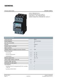
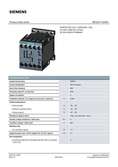
<strong>Product</strong> <strong>data</strong> <strong>sheet</strong><strong>3RT2017</strong>-<strong>1AP01</strong>CONTACTOR, AC-3, 5.5KW/400V, 1NO,AC 230V, 50/60 HZ, 3-POLE,SZ S00 SCREW TERMINALGeneral technical <strong>data</strong>:product brand nameproduct designationSize of the contactorProtection class IP / on the frontSIRIUS3RT2 contactorS00IP20Degree of pollution 3Installation altitude / at a height over sea level / maximum m 2,000Ambient temperature• during storage °C -55 … 80• during the operating phase °C -25 … 60• during transport °C -55 … 80Resistance against shock9.8g / 5 ms and 5.9g / 10 msImpulse voltage resistance / rated value kV 6Insulation voltage / rated value V 690Resistive loss• per conductor / typical W 1.2Apparent power loss / of the magnet coil / for AC / typical V·A 5.7Item designation• according to DIN 40719 extendable after IEC 204-2 / accordingto IEC 750K<strong>3RT2017</strong>-<strong>1AP01</strong>Page 1/ 704/27/2011subject to modifications© Copyright Siemens AG 2011
• according to DIN EN 61346-2QMechanical operating cycles as operating time• of the contactor / typical 30,000,000• of the contactor with added auxiliary switch block / typical 10,000,000• of the contactor with added electronics-compatible auxiliaryswitch block / typical5,000,000Main circuit:Number of poles / for main current circuit 3Number of NC contacts / for main contacts 0Number of NO contacts / for main contacts 3Operating voltage / at AC-3 / rated value• maximum V 690Operating current / at AC-1 / at 400 V• at 40 °C ambient temperature / rated value A 22• at 60 °C ambient temperature / rated value A 20Operating current• at AC-2 / at 400 V / rated value A 12• at AC-3 / at 400 V / rated value A 12• at AC-4 / at 400 V / rated value A 8.5• with 1 current path / at DC-1• at 24 V / rated value A 20• at 110 V / rated value A 2.1• with 2 current paths in series / at DC-1• at 24 V / rated value A 20• at 110 V / rated value A 12• with 3 current paths in series / at DC-1• at 24 V / rated value A 20• at 110 V / rated value A 20• with 1 current path / at DC-3 / at DC-5• at 24 V / rated value A 20• at 110 V / rated value A 0.1• with 2 current paths in series / at DC-3 / at DC-5• at 24 V / rated value A 20• at 110 V / rated value A 0.35• with 3 current paths in series / at DC-3 / at DC-5• at 24 V / rated value A 20• at 110 V / rated value A 20Service power• at AC-2 / at 400 V / rated value W 5,500<strong>3RT2017</strong>-<strong>1AP01</strong>Page 2/ 704/27/2011subject to modifications© Copyright Siemens AG 2011
• at AC-3• at 400 V / rated value W 5,500• at 500 V / rated value W 5,500• at 690 V / rated value W 5,500• at AC-4 / at 400 V / rated value W 4,000Operating reactive power / at AC-6b• at 230 V / rated value var 0• at 400 V / rated value var 0• at 690 V / rated value var 0Off-load operating frequency 1/h 10,000Frequency of operation• at AC-1 / according to IEC 60947-6-2 / maximum 1/h 1,000• at AC-2 / according to IEC 60947-6-2 / maximum 1/h 750• at AC-3 / according to IEC 60947-6-2 / maximum 1/h 750• at AC-4 / according to IEC 60947-6-2 / maximum 1/h 250Control circuit:Design of activation of the operating mechanismType of voltage / of the controlled supply voltageconventionalACControl supply voltage frequency• 1 / rated value Hz 50• 2 / rated value Hz 60Control supply voltage / 1• at 50 Hz / for AC• rated value V 230• at 60 Hz / for AC• rated value V 230Operating range factor control supply voltage rated value / ofthe solenoid• at 50 Hz / for AC 0.8 … 1.1• at 60 Hz / for AC 0.85 … 1.1Apparent pull-in power / of the solenoid / for AC V·A 37Apparent holding power / of the solenoid / for AC V·A 5.7Inductive power factor• with the pull-in power of the coil 0.8• with the pull-in power of the coil 0.25Auxiliary circuit:<strong>Product</strong> extension / auxiliary switchContact reliability / of the auxiliary contactsYes1 faulty switching per 100 million (17 V, 1 mA)Number of NC contacts / for auxiliary contacts<strong>3RT2017</strong>-<strong>1AP01</strong>Page 3/ 704/27/2011subject to modifications© Copyright Siemens AG 2011
• instantaneous switching 0• lagging switching 0Number of NO contacts / for auxiliary contacts• instantaneous switching 1• leading switching 0Operating current / of the auxiliary contacts• at AC-12 / maximum A 10• at AC-15• at 230 V A 10• at 400 V A 3• at DC-12• at 48 V A 6• at 60 V A 6• at 110 V A 3• at 220 V A 1• at DC-13• at 24 V A 6• at 48 V A 2• at 60 V A 2• at 110 V A 1• at 220 V A 0.3Short-circuit:Design of the fuse link• for short-circuit protection of the auxiliary switch / requiredfuse gL/gG: 10 A• for short-circuit protection of the main circuit• with type of assignment 1 / required gL/gG LV HRC 3NA, DIAZED 5SB, NEOZED 5SE: 35A• at type of coordination 2 / requiredgL/gG LV HRC 3NA, DIAZED 5SB, NEOZED 5SE:20AInstallation/mounting/dimensions:Built in orientationType of mountingType of fixing/fixation / series installationverticalscrew and snap-on mounting onto 35 mm standardmounting rail according to DIN EN 50022YesWidth mm 45Height mm 57.5Depth mm 73Distance, to be maintained, to the ranks assembly• forwards mm 0• backwards mm 0<strong>3RT2017</strong>-<strong>1AP01</strong>Page 4/ 704/27/2011subject to modifications© Copyright Siemens AG 2011
• upwards mm 6• downwards mm 6• sidewards mm 0Distance, to be maintained, to earthed part• forwards mm 6• backwards mm 0• upwards mm 6• downwards mm 6• sidewards mm 6Distance, to be maintained, conductive elements• forwards mm 6• backwards mm 6• upwards mm 6• downwards mm 10• sidewards mm 6Connections:Design of the electrical connection• for main current circuit• for auxiliary and control current circuitscrew-type terminalsscrew-type terminalsType of the connectable conductor cross-section• for main contacts• solid• stranded2x (0.5 ... 1.5 mm2), 2x (0.75 ... 2.5 mm2), 2x 4 mm22x (0.5 ... 1.5 mm2), 2x (0.75 ... 2.5 mm2), 2x 4 mm2• finely stranded• with conductor end processing2x (0.5 ... 1.5 mm2), 2x (0.75 ... 2.5 mm2)• for AWG conductors / for main contacts 2x (20 ... 16), 2x (18 ... 14), 2x 12• for auxiliary contacts• solid2x (0.5 ... 1.5 mm2), 2x (0.75 ... 2.5 mm2), 2x 4 mm2• finely stranded• with conductor end processing2x (0.5 ... 1.5 mm2), 2x (0.75 ... 2.5 mm2)• for AWG conductors / for auxiliary contacts 2x (20 ... 16), 2x (18 ... 14), 2x 12Certificates/approvals:Verification of suitabilityCE / UL / CSA / CCC<strong>3RT2017</strong>-<strong>1AP01</strong>Page 5/ 704/27/2011subject to modifications© Copyright Siemens AG 2011
General <strong>Product</strong> ApprovalTest CertificatesCQC ROSTEST ManufacturerShipping ApprovalPRSotherManufacturerUL/CSA ratingsyielded mechanical performance (hp)• for single-phase squirrel cage motors• at 110/120 V / rated value hp 0.5• at 230 V / rated value hp 2• for three-phase squirrel cage motors• at 200/208 V / rated value hp 3• at 220/230 V / rated value hp 3• at 460/480 V / rated value hp 7.5• at 575/600 V / rated value hp 10Operating current (FLA) / for three-phase squirrel cage motors• at 480 V / rated value A 11• at 600 V / rated value A 11Contact rating designation / for auxiliary contacts / according toULA600 / Q600Safety:B10 value / with high demand rate• according to SN 31920 1,000,000T1 value / for proof test interval or service life• according to IEC 61508 a 20Proportion of dangerous failures• with low demand rate / according to SN 31920 % 40• with high demand rate / according to SN 31920 % 75Failure rate (FIT value) / with low demand rate• according to SN 31920 FIT 100Protection against electrical shockfinger-safeFurther information:Information- and Downloadcenter (Catalogs, Brochures,…)http://www.siemens.com/industrial-controls/catalogsIndustry Mall (Online ordering system)http://www.siemens.com/industrial-controls/mall<strong>3RT2017</strong>-<strong>1AP01</strong>Page 6/ 704/27/2011subject to modifications© Copyright Siemens AG 2011
CAx-Online-Generatorhttp://www.siemens.com/caxService&Support (Manuals, Certificates, Characteristics, FAQs,...)http://support.automation.siemens.com/WW/view/en/<strong>3RT2017</strong>-<strong>1AP01</strong>/allImage <strong>data</strong>base (product images, 2D dimension drawings, 3D models, device circuit diagrams, ...)http://www.automation.siemens.com/bilddb/cax_en.aspx?mlfb=<strong>3RT2017</strong>-<strong>1AP01</strong>last change: Apr 4, 2011<strong>3RT2017</strong>-<strong>1AP01</strong>Page 7/ 704/27/2011subject to modifications© Copyright Siemens AG 2011