E2E - OMRON Industrial Automation
E2E - OMRON Industrial Automation
E2E - OMRON Industrial Automation
You also want an ePaper? Increase the reach of your titles
YUMPU automatically turns print PDFs into web optimized ePapers that Google loves.
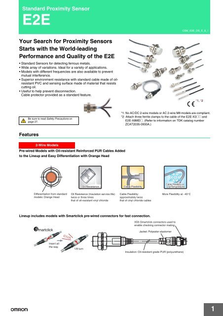
Standard Proximity Sensor<strong>E2E</strong>Your Search for Proximity SensorsStarts with the World-leadingPerformance and Quality of the <strong>E2E</strong>• Standard Sensors for detecting ferrous metals.• Wide array of variations. Ideal for a variety of applications.• Models with different frequencies are also available to preventmutual interference.• Superior environment resistance with standard cable made of oilresistantPVC and sensing surface made of material that resistscutting oil.• Useful to help prevent disconnection.Cable protector provided as a standard feature.CSM_<strong>E2E</strong>_DS_E_8_1*1, *2Be sure to read Safety Precautions onpage 27.*1: No AC/DC 2-wire models or AC 2-wire M8 models are compliant.*2: Attach three ferrite clamps to the cable of the <strong>E2E</strong>-X3@@ and<strong>E2E</strong>-X8MD@. (Refer to information on TDK catalog numberZCAT2035-0930A.)Features2-Wire ModelsPre-wired Models with Oil-resistant Reinforced PUR Cables Addedto the Lineup and Easy Differentiation with Orange HeadOil ResistanceCable FlexibilityCable Flexibility atLow TemperaturesDifferentiation from standardmodels: Orange HeadOil Resistance (Insulation service life):twice or three timesthat of oil-resistant vinyl chlorideCable Flexibility:approximately twicethat of cinyl chloride cablesMore Flexibility at −40°CLineup includes models with Smartclick pre-wired connectors for fast connection.XS5 Smartclick connectors used toenable checking connector matingJacket: Polyester elastomerClickInsert allthe way.1/8 turnInsulation: Oil-resistant grade PUR (polyurethane)1
<strong>E2E</strong>Lineup includes models with self-diagnostic output to provide notification of failures andunstable detection conditions, such as coil burnout.• Contributes to preventive maintenance to keep the line from stopping.Reduced wiring, fewer resources, and low power consumption contribute toenvironmentalism.• Wiring work and amount of copper wire used reduced to two thirds of that required for 3-wire models.• Current consumption drastically reduced to less than 10% (when a DC 2-wire model is compared with a DC 3-wire model).3-Wire ModelsLineup includes models with small diameter (3 dia., 4 dia., 5.4 dia., M5)• All small-diameter models use sealed construction. Operation is stable even when the Sensor is mounted in a small space or embedded in metal.• Bright indicators enable easily checking the installation condition.Wide range of ambient operating temperatures: −40°C to 85°C (M8 to M30 models)• Wide range of ambient operating temperatures also for small-diameter models: −25°C to 70°C• Suitable for low-temperature and high-temperature applications, which are troublesome for photoelectric sensors.Lineup includes models with flexible cable (4-dia. to M30 models)• Reduced risk of disconnection in applications with moving parts.2
Models Listed by <strong>E2E</strong> Type<strong>E2E</strong>●: Standard Models, ▲: Different frequency, @: Self-diagnosis, ■: Different frequency and self-diagnosis,---: Not listed2-Wire ModelsPowersupplyShieldingSize and sensing distancePolarityOperationmodeOil-resistantreinforcedPUR cableM12 pre-wiredsmartclickconnector modelsPre-wired modelwith 2-mcableM12 pre-wiredsmartclickconnector modelsStandard cable and flexible cable(cable material: oil-resistant PVC)/Connector modelsPre-wired modelwith standard2-m cablePre-wired modelwith flexible2-m cablePre-wired modelwith standard5-m cableM12 connector (IECpin arrangement)M12 standardpre-wiredconnector modelsM8 connectorM12 connector (oldpin arrangement)OrderingInformationPageDimensions referencechartDCACAC/DCShieldedUnshieldedShieldedUnshieldedShieldedM82 mM123 mmM187 mmM3010 mmM84 mmM128 mmM1814 mmM3020 mmM81.5 mmM122 mmM185 mmM3010 mmM82 mmM125 mmM1810 mmM3018 mmM122 mmM185 mmM3010 mmYesYesNoYesNoYesNoYes------NO ● ● ● ● ● ● ● --- ● ●NC ● ● --- ● --- ● ● --- ● ●Refer toNO ● ● ● ●▲@■ ● ● ●▲@ ● --- ● page 7.NC ● ● --- ● --- ● ● ● --- ●Refer toNONC------------------------------------------●---------------Modelswith SelfdiagnosticOutput onNO ● ● ● ●▲@■ ● ● ●▲@ ● --- ● page 8.NC ● ● --- ● --- ● ● ● --- ●Refer toNONC------------------------------------------●●------------Modelswith conventionalconnectorNO ● ● ● ●▲@■ ● ● ●▲@ ● --- ● pin assignmentsonNC ● ● --- ● --- --- ● ● --- ●page 9.NO --- --- --- --- --- --- --- ● --- ---NC --- --- --- --- --- --- --- ● --- ---NO --- --- --- ● ● ● ● --- ● ● Refer topage 8.NC --- --- --- ● --- --- ● --- ● ●Refer toNO --- --- ● ●▲@■ ● ● ●▲@ ● --- ● Modelswith SelfdiagnosticNC --- --- --- ● --- --- ● --- --- ●NO --- --- ● ●▲@■ ● ● ●▲@ ● --- ● Output orModelsNC --- --- --- ● --- --- ● ● --- ● with conventionalNO --- --- ● ●▲@■ ● ● ●▲@ ● --- ● connectorpin assignmentsNC --- --- --- ● --- --- ● --- --- ●onpage 9.NO --- --- --- ● --- --- --- --- --- ---NC --- --- --- ● --- --- --- --- --- ---NO --- --- --- ●▲ --- ● ● --- --- ---NC --- --- --- ● --- --- ● --- --- ---NO --- --- --- ●▲ --- ● ● --- --- ---NC --- --- --- ● --- --- ● --- --- ---NO --- --- --- ●▲ --- ● ● --- --- ---NC --- --- --- ● --- --- ● --- --- ---NO --- --- --- ● --- --- --- --- --- ---NC --- --- --- ● --- --- --- --- --- ---NO --- --- --- ●▲ --- ● ● --- --- ---NC --- --- --- ● --- --- ● --- --- ---NO --- --- --- ●▲ --- --- ● --- --- ---NC --- --- --- ● --- --- ● --- --- ---NO --- --- --- ●▲ --- --- ● --- --- ---NC --- --- --- ● --- --- ● --- --- ---NO --- --- --- ● --- --- --- --- --- ---NC --- --- --- --- --- --- --- --- --- ---NO --- --- --- ● --- ● --- --- --- ---NC --- --- --- --- --- --- --- --- --- ---NO --- --- --- ● --- --- --- --- --- ---NC --- --- --- --- --- --- --- --- --- ---Referto page10.Referto page29.3
<strong>E2E</strong>●: Standard Models, ▲: Different frequency, ---: Not listed3-Wire ModelsPowersupplyShieldingSize and sensing distancePolarityOperationmodeOil-resistantreinforcedPUR cableM12 pre-wiredsmartclickconnector modelsPre-wired modelwith 2-m cableM12 pre-wiredsmartclickconnector modelsStandard cable and flexible cable(cable material: oil-resistant PVC)/Connector modelsPre-wired modelwith standard2-m cablePre-wired modelwith flexible2-m cablePre-wired modelwith standard5-m cableM12 connector (IECpin arrangement)M12 standard prewiredconnector modelsM8 connectorOrderingInformationPageDimensions referencechartDCNPNDCPNPShieldedUnshieldedShieldedUnshielded3 dia.0.6 mm4 dia.0.8 mmM51 mm5.4 dia.1 mmM81.5mmM122 mmM185 mmM3010 mmM82 mmM125 mmM1810 mmM3018 mm3 dia.0.6 mm4 dia.0.8 mmM51 mm5.4 dia.1 mmM81.5mmM122 mmM185 mmM3010 mmM82 mmM125 mmM1810 mmM3018 mmYesYesNO --- --- --- ● --- --- --- --- ---NC --- --- --- ● --- --- --- --- ---NO --- --- --- ● ● ● --- --- ---NC --- --- --- ● --- --- --- --- ---NO --- --- --- ● ● ● --- --- ---NC --- --- --- ● --- --- --- --- ---NO --- --- --- ● ● ● --- --- ---NC --- --- --- ● --- --- --- --- ---NO --- --- --- ● ● ● ● --- ●NC --- --- --- ● --- --- ● --- ●NO --- --- --- ●▲ ● ● ● --- ---NC --- --- --- ● --- --- ● --- ---NO --- --- --- ●▲ ● ● ● --- ---NC --- --- --- ● --- --- ● --- ---NO --- --- --- ●▲ ● ● ● --- ---NC --- --- --- ● --- --- ● --- ---NO --- --- --- ● ● --- ● --- ●NC --- --- --- ● --- --- ● --- ●NO --- --- --- ●▲ ● ● ● --- ---NC --- --- --- ● --- --- ● --- ---NO --- --- --- ●▲ ● ● ● --- ---NC --- --- --- ● --- --- ● --- ---NO --- --- --- ●▲ ● ● ● --- ---NC --- --- --- ● --- --- ● --- ---NO --- --- --- ● --- --- --- --- ---NC --- --- --- ● --- --- --- --- ---NO --- --- --- ● ● --- --- --- ---NC --- --- --- ● --- --- --- --- ---NO --- --- --- ● ● --- --- --- ---NC --- --- --- ● --- --- --- --- ---NO --- --- --- ● --- --- --- --- ---NC --- --- --- ● --- --- --- --- ---NO --- --- --- ● ● ● ● --- ●NC --- --- --- ● --- --- ● --- ●NO --- --- --- ●▲ ● ● ● --- ---NC --- --- --- ● --- --- ● --- ---NO --- --- --- ●▲ ● ● ● --- ---NC --- --- --- ● --- --- ● --- ---NO --- --- --- ● ● --- ● --- ---NC --- --- --- ● --- --- ● --- ---NO --- --- --- ● ● --- ● --- ●NC --- --- --- ● --- --- ● --- ●NO --- --- --- ● ● --- ● --- ---NC --- --- --- ● --- --- ● --- ---NO --- --- --- ● ● --- ● --- ---NC --- --- --- ● --- --- ● --- ---NO --- --- --- ● ● --- ● --- ---NC --- --- --- ● --- --- ● --- ---Referto page11.Referto page12.Referto page11.Referto page12.Referto page29.4
<strong>E2E</strong>2-Wire ModelsUnshielded DC 2-Wire Models with No Self-diagnosis Output [Refer to Dimensions on page 29.]M8M12M18M30Sensing distance4 mm8 mm14 mm20 mmConnectionmethodPre-wired Models (2 m)CablespecificationsPVC (oil-resistant)M12 Connector Models ---M8 Connector Models ---12M Pre-wired SmartclickConnector Models(0.3m)Pre-wired Models (2 m)*1. Models with different frequencies are also available. The model number is <strong>E2E</strong>-X @D15 (example: <strong>E2E</strong>-X8MD15 2M).*2. Models with a flexible cable are also available. Add -R to the end of the model number. (example: <strong>E2E</strong>-X4MD1-R 2M).*3. The standard stock includes models with a cable length of 5 m. Specify the cable length at the end of the model number. (Example: <strong>E2E</strong>-X4MD1 5M)*4. Refer to page 24 for details.AppearancePolarityOperationmodePinarrangementShielded DC 2-Wire Models with Self-diagnosis Output [Refer to Dimensions on page 29.]NONCApplicableconnectorcode *4--- ---Model<strong>E2E</strong>-X4MD1 2M *2*3<strong>E2E</strong>-X4MD2 2MNO 1: +V, 4: 0 V A <strong>E2E</strong>-X4MD1 2MNC 1: +V, 2: 0 V D <strong>E2E</strong>-X4MD2-M1GNO 1: +V, 4: 0 V<strong>E2E</strong>-X4MD1-M3GINC 1: +V, 2: 0 V <strong>E2E</strong>-X4MD2-M3GPVC (oil-resistant) NO 1: +V, 4: 0 V G <strong>E2E</strong>-X8MD1-M1TGJ 0.3MPVC (oil-resistant)M12 Connector Models ---M12 Standard PrewiredConnector Models(0.3 m)12M Pre-wired SmartclickConnector Models(0.3m)Pre-wired Models (2 m)PVC (oil-resistant)NO<strong>E2E</strong>-X8MD1 2M *1*2*3--- ---NC<strong>E2E</strong>-X8MD2 2MNO 1: +V, 4: 0 V A <strong>E2E</strong>-X8MD1-M1G *1NC 1: +V, 2: 0 V D <strong>E2E</strong>-X8MD2-M1GNO 1: +V, 4: 0 V A <strong>E2E</strong>-X8MD1-M1GJ 0.3MNC 1: +V, 2: 0 V D ---PVC (oil-resistant) Yes NO 1: +V, 4: 0 V G <strong>E2E</strong>-X14MD1-M1TGJ 0.3MPVC (oil-resistant)M12 Connector Models ---M12 Standard PrewiredConnector Models(0.3 m)12M Pre-wired SmartclickConnector Models(0.3m)Pre-wired Models (2 m)PVC (oil-resistant)NO<strong>E2E</strong>-X14MD1 2M *1*2*3--- ---NC<strong>E2E</strong>-X14MD2 2MNO 1: +V, 4: 0 V A <strong>E2E</strong>-X14MD1-M1G *1NC 1: +V, 2: 0 V D <strong>E2E</strong>-X14MD2-M1GNO 1: +V, 4: 0 V A <strong>E2E</strong>-X14MD1-M1GJ 0.3MNC 1: +V, 2: 0 V D <strong>E2E</strong>-X14MD2-M1GJ 0.3MPVC (oil-resistant) NO 1: +V, 4: 0 V G <strong>E2E</strong>-X20MD1-M1TGJ 0.3MPVC (oil-resistant)M12 Connector Models ---M12 Standard PrewiredConnector Models(0.3 m)PVC (oil-resistant)NO<strong>E2E</strong>-X20MD1 2M *1*2*3--- ---NC<strong>E2E</strong>-X20MD2 2MNO 1: +V, 4: 0 V A <strong>E2E</strong>-X20MD1-M1G *1NC 1: +V, 2: 0 V D <strong>E2E</strong>-X20MD2-M1GNO 1: +V, 4: 0 V A <strong>E2E</strong>-X20MD1-M1GJ 0.3MNC 1: +V, 2: 0 V D ---M12M18M30Sensing distance3 mm7 mm10 mmConnectionmethodPre-wired Models(2 m)M12 ConnectorModelsPre-wired Models(2 m)M12 ConnectorModelsPre-wired Models(2 m)M12 ConnectorModelsCablespecificationsPVC (oil-resistant)AppearancePolarityOperationmodePinarrangement*1. Models with different frequencies are also available. The model number is <strong>E2E</strong>-X @D15S (example: <strong>E2E</strong>-X3D15S 2M).*2. Refer to page 24 for details.---Applicableconnectorcode *2Model--- --- <strong>E2E</strong>-X3D1S 2M *12: +V and diagnostic output3: 0 V4: +V and control outputPVC (oil-resistant) --- --- <strong>E2E</strong>-X7D1S 2M *1Yes NO 2: +V and diagnostic output---3: 0 VD <strong>E2E</strong>-X7D1S-M14: +V and control outputD<strong>E2E</strong>-X3D1S-M1PVC (oil-resistant) --- --- <strong>E2E</strong>-X10D1S 2M *1---2: +V and diagnostic output3: 0 V4: +V and control outputD<strong>E2E</strong>-X10D1S-M18
<strong>E2E</strong>2-Wire ModelsUnshielded DC 2-Wire Models with Self-diagnosis Output [Refer to Dimensions on page 29.]M12M18M30Sensing distance8 mm14 mm20 mmConnectionmethodPre-wired Models(2 m)M12 ConnectorModelsPre-wired Models(2 m)M12 ConnectorModelsPre-wired Models(2 m)M12 ConnectorModelsCablespecificationsPVC (oil-resistant)AppearancePolarityOperationmodePinarrangement*1. Models with different frequencies are also available. The model number is <strong>E2E</strong>-X @MD15S (example: <strong>E2E</strong>-X8MD15S 2M).*2. Refer to page 24 for details.---Applicableconnectorcode *2Model--- --- <strong>E2E</strong>-X8MD1S 2M *2: +V and diagnostic output3: 0 V4: +V and control outputPVC (oil-resistant) --- --- <strong>E2E</strong>-X14MD1S 2M *Yes NO 2: +V and diagnostic output---3: 0 VD <strong>E2E</strong>-X14MD1S-M14: +V and control outputD<strong>E2E</strong>-X8MD1S-M1PVC (oil-resistant) --- --- <strong>E2E</strong>-X20MD1S 2M *---2: +V and diagnostic output3: 0 V4: +V and control outputD<strong>E2E</strong>-X20MD1S-M1Connector Pin Assignments of DC 2-Wire Models• The connector pin assignments of each New <strong>E2E</strong> DC 2-Wire Modelconform to IEC 947-5-2 Table III. (Only DC 2-Wire Models havebeen changed in comparison to the previous models.)• The following models with conventional connector pin assignmentsare available as well. (Only NO Models can be used.)The cable at the right should also be used if the XW3A-P@45-G11Connector Junction Box is already being used.Cable lengthModel500 mm XS2W-D421-BY1Internal Wiring14(Proximity Sensor end)(Wired end)43Models with conventional connector pin assignments are available as well.AppearanceShieldedUnshieldedNote: Refer to page 24 for details.ModelNO Applicable connector code * NC Applicable connector code *M8 <strong>E2E</strong>-X2D1-M1 C <strong>E2E</strong>-X2D2-M1 DM12 <strong>E2E</strong>-X3D1-M1 C <strong>E2E</strong>-X3D2-M1 DM18 <strong>E2E</strong>-X7D1-M1 C <strong>E2E</strong>-X7D2-M1 DM30 <strong>E2E</strong>-X10D1-M1 C <strong>E2E</strong>-X10D2-M1 DM8 <strong>E2E</strong>-X4MD1-M1 C <strong>E2E</strong>-X4MD2-M1 DM12 <strong>E2E</strong>-X8MD1-M1 C <strong>E2E</strong>-X8MD2-M1 DM18 <strong>E2E</strong>-X14MD1-M1 C <strong>E2E</strong>-X14MD2-M1 DM30 <strong>E2E</strong>-X20MD1-M1 C <strong>E2E</strong>-X20MD2-M1 D9
<strong>E2E</strong>2-Wire ModelsAC 2-Wire Models Shielded Models [Refer to Dimensions on page 29.]AppearanceM8M12M18M30*1. Models with different frequencies are also available. The model number is <strong>E2E</strong>-X @Y@5 (example: <strong>E2E</strong>-X5Y15 2M).*2. The standard stock includes models with a cable length of 5 m. Specify the cable length at the end of the model number. (Example: <strong>E2E</strong>-X2Y1 5M)*3. Refer to page 24 for details.Unshielded ModelsSensing distance1.5 mm2 mm5 mm10 mmConnectionmethodPre-wired Models(2 m)Pre-wired Models(2 m)M12 ConnectorModelsPre-wired Models(2 m)M12 ConnectorModelsPre-wired Models(2 m)M12 ConnectorModelsCablespecificationsPVC (oil-resistant)PVC (oil-resistant)---PVC (oil-resistant)---PVC (oil-resistant)---OperationmodeNONCNONCPinarrangementApplicable connectorcode *3Model--- ---<strong>E2E</strong>-X1R5Y1 2M<strong>E2E</strong>-X1R5Y2 2M--- ---<strong>E2E</strong>-X2Y1 2M *1*2<strong>E2E</strong>-X2Y2 2MNO (3, 4): (AC, AC) E <strong>E2E</strong>-X2Y1-M1NC (1, 2): (AC, AC) F <strong>E2E</strong>-X2Y2-M1NO<strong>E2E</strong>-X5Y1 2M *1*2--- ---NC<strong>E2E</strong>-X5Y2 2MNO (3, 4): (AC, AC) E <strong>E2E</strong>-X5Y1-M1NC (1, 2): (AC, AC) F <strong>E2E</strong>-X5Y2-M1NO<strong>E2E</strong>-X10Y1 2M *1*2--- ---NC<strong>E2E</strong>-X10Y2 2MNO (3, 4): (AC, AC) E <strong>E2E</strong>-X10Y1-M1NC (1, 2): (AC, AC) F <strong>E2E</strong>-X10Y2-M1AppearanceM8M12M18M30Sensing distance2 mm5 mm10 mm18 mmConnectionmethodPre-wired Models(2 m)Pre-wired Models(2 m)M12 ConnectorModelsPre-wired Models(2 m)M12 ConnectorModelsPre-wired Models(2 m)M12 ConnectorModelsCablespecificationsPVC (oil-resistant)PVC (oil-resistant)OperationmodeNONCNONC*1. Models with different frequencies are also available. The model number is <strong>E2E</strong>-X @MY@5 (example: <strong>E2E</strong>-X5MY15 2M).*2. The standard stock includes models with a cable length of 5 m. Specify the cable length at the end of the model number. (Example: <strong>E2E</strong>-X5MY1 5M)*3. Refer to page 24 for details.AC 2-Wire Models Shielded Models [Refer to Dimensions on page 29.](There are no unshielded models.)---PVC (oil-resistant)---PVC (oil-resistant)---PinarrangementApplicable connectorcode *3Model--- ---<strong>E2E</strong>-X2MY1 2M<strong>E2E</strong>-X2MY2 2M--- ---<strong>E2E</strong>-X5MY1 2M *1*2<strong>E2E</strong>-X5MY2 2MNO (3, 4): (AC, AC) E <strong>E2E</strong>-X5MY1 2MNC (1, 2): (AC, AC) F <strong>E2E</strong>-X5MY2-M1NO<strong>E2E</strong>-X10MY1 2M *1--- ---NC<strong>E2E</strong>-X10MY2 2MNO (3, 4): (AC, AC) E <strong>E2E</strong>-X10MY1-M1NC (1, 2): (AC, AC) F <strong>E2E</strong>-X10MY2-M1NO<strong>E2E</strong>-X18MY1 2M *1--- ---NC<strong>E2E</strong>-X18MY2 2MNO (3, 4): (AC, AC) E <strong>E2E</strong>-X18MY1-M1NC (1, 2): (AC, AC) F <strong>E2E</strong>-X18MY2-M1AppearanceM12M18M30Sensing distance3 mm7 mm10 mmConnectionmethodPre-wired Models(2 m)Pre-wired Models(2 m)Pre-wired Models(2 m)CablespecificationsPVC (oil-resistant)PVC (oil-resistant)PVC (oil-resistant)OperationmodePinarrangementApplicable connectorcode *3Note: Not compliant with CE.* The standard stock includes models with a cable length of 5 m. Specify the cable length at the end of the model number. (Example: <strong>E2E</strong>-X7T1 5M)NO--- --- <strong>E2E</strong>-X3T1 2MModel--- --- <strong>E2E</strong>-X7T1 2M *--- --- <strong>E2E</strong>-X10T1 2M10
<strong>E2E</strong>3-Wire ModelsShielded DC 3-Wire Models [Refer to Dimensions on page 29.]Appearance3 dia.4 dia.M55.4 dia.M8M12M18M30Sensing distance0.6 mm0.8 mm1 mm1 mm1.5 mm2 mm5 mm10 mmConnectionmethodPre-wired Models(2 m)Pre-wired Models(2 m)Pre-wired Models(2 m)Pre-wired Models(2 m)Pre-wired Models(2 m)M12 ConnectorModelsM8 ConnectorModelsPre-wired Models(2 m)M12 ConnectorModelsPre-wired Models(2 m)M12 ConnectorModelsPre-wired Models(2 m)M12 ConnectorModelsPVC (oil-resistant)PVC (oil-resistant)PVC (oil-resistant)PVC (oil-resistant)PVC (oil-resistant)PVC (oil-resistant)------PVC (oil-resistant)---PVC (oil-resistant)---PVC (oil-resistant)---*1. The standard stock includes models with a cable length of 5 m. Specify the cable length at the end of the model number. (Example: <strong>E2E</strong>-X2E1 5M)*2. Models with a flexible cable are also available. Add -R to the end of the model number. (example: <strong>E2E</strong>-X5E1-R 2M).*3. Models with different frequencies are also available. The model number is <strong>E2E</strong>-X@@@5 (example: <strong>E2E</strong>-X5E15 2M).*4. Refer to page 24 for details.CablespecificationsOperationmodePinarrangementApplicableconnectorcode NPN output*5<strong>E2E</strong>-CR6C1 2MModelPNP outputNO<strong>E2E</strong>-CR6B1 2M--- ---NC <strong>E2E</strong>-CR6C2 2M <strong>E2E</strong>-CR6B2 2MNO<strong>E2E</strong>-CR8C1 2M *1*2 <strong>E2E</strong>-CR8B1 2M *2--- ---NC <strong>E2E</strong>-CR8C2 2M <strong>E2E</strong>-CR8B2 2MNO<strong>E2E</strong>-X1C1 2M *1*2 <strong>E2E</strong>-X1B1 2M *2--- ---NC <strong>E2E</strong>-X1C2 2M <strong>E2E</strong>-X1B2 2MNO<strong>E2E</strong>-C1C1 2M *1*2 <strong>E2E</strong>-C1B1 2M--- ---NC <strong>E2E</strong>-C1C2 2M <strong>E2E</strong>-C1B2 2MNO<strong>E2E</strong>-X1R5E1 2M *1*2 <strong>E2E</strong>-X1R5F1 2M *1*2--- ---NC <strong>E2E</strong>-X1R5E2 2M <strong>E2E</strong>-X1R5F2 2MNO1: +V, 3: 0 V,4: Control outputB <strong>E2E</strong>-X1R5E1-M1 <strong>E2E</strong>-X1R5F1-M1NC1: +V, 3: 0 V,2: Control outputD <strong>E2E</strong>-X1R5E2-M1 <strong>E2E</strong>-X1R5F2-M11: +V, 3: 0 V,NO<strong>E2E</strong>-X1R5E1-M3 <strong>E2E</strong>-X1R5F1-M34: Control outputI1: +V, 3: 0 V,NC2: Control output<strong>E2E</strong>-X1R5E2-M3 <strong>E2E</strong>-X1R5F2-M3NO<strong>E2E</strong>-X2E1 2M *1*2*3 <strong>E2E</strong>-X2F1 2M *1*2*3--- ---NC <strong>E2E</strong>-X2E2 2M <strong>E2E</strong>-X2F2 2MNO1: +V, 3: 0 V,4: Control outputB <strong>E2E</strong>-X2E1-M1 <strong>E2E</strong>-X2F1-M1NC1: +V, 3: 0 V,2: Control outputD <strong>E2E</strong>-X2E2-M1 <strong>E2E</strong>-X2F2-M1NO<strong>E2E</strong>-X5E1 2M *1*2*3 <strong>E2E</strong>-X5F1 2M *1*2*3--- ---NC <strong>E2E</strong>-X5E2 2M <strong>E2E</strong>-X5F2 2MNO1: +V, 3: 0 V,4: Control outputB <strong>E2E</strong>-X5E1-M1 <strong>E2E</strong>-X5F1-M1NC1: +V, 3: 0 V,2: Control outputD <strong>E2E</strong>-X5E2-M1 <strong>E2E</strong>-X5F2-M1NO<strong>E2E</strong>-X10E1 2M *1*2*3 <strong>E2E</strong>-X10F1 2M *2--- ---NC <strong>E2E</strong>-X10E2 2M <strong>E2E</strong>-X10F2 2MNO1: +V, 3: 0 V,4: Control outputB <strong>E2E</strong>-X10E1-M1 <strong>E2E</strong>-X10F1-M1NC1: +V, 3: 0 V,2: Control outputD <strong>E2E</strong>-X10E2-M1 <strong>E2E</strong>-X10F2-M111
<strong>E2E</strong>3-Wire ModelsUnshielded DC 3-Wire Models [Refer to Dimensions on page 29.]M8M12M18M30Sensing distance2 mm5 mm10 mm18 mmConnectionmethodPre-wired Models(2 m)M12 ConnectorModelsM8 ConnectorModelsPre-wired Models(2 m)M12 ConnectorModelsPre-wired Models(2 m)M12 ConnectorModelsPre-wired Models(2 m)M12 ConnectorModelsCablespecificationsPVC (oil-resistant)------PVC (oil-resistant)---PVC (oil-resistant)---PVC (oil-resistant)---*1. The standard stock includes models with a cable length of 5 m. Specify the cable length at the end of the model number. (Example: <strong>E2E</strong>-X5ME1 5M)*2. Models with a flexible cable are also available. Add -R to the end of the model number. (example: <strong>E2E</strong>-X5E1-R 2M).*3. Models with different frequencies are also available. The model number is <strong>E2E</strong>-X@M@@5 (example: <strong>E2E</strong>-X5ME15 2M).*4. Refer to page 24 for details.AppearanceOperationmodePinarrangementApplicableModelconnectorcode*5NPN output PNP output<strong>E2E</strong>-X2ME1 2M *2 <strong>E2E</strong>-X2MF1 2M *2NO--- ---NC <strong>E2E</strong>-X2ME2 2M <strong>E2E</strong>-X2MF2 2MNO1: +V, 3: 0 V,4: Control outputB <strong>E2E</strong>-X2ME1-M1 <strong>E2E</strong>-X2MF1-M1NC1: +V, 3: 0 V,2: Control outputD <strong>E2E</strong>-X2ME2-M1 <strong>E2E</strong>-X2MF2-M11: +V, 3: 0 V,NO4: Control output<strong>E2E</strong>-X2ME1-M3 <strong>E2E</strong>-X2MF1-M3INC1: +V, 3: 0 V,<strong>E2E</strong>-X2ME2-M3 <strong>E2E</strong>-X2MF2-M32: Control outputNO<strong>E2E</strong>-X5ME1 2M--- --- *1*2*3<strong>E2E</strong>-X5MF1 2M *2NC <strong>E2E</strong>-X5ME2 2M <strong>E2E</strong>-X5MF2 2MNO1: +V, 3: 0 V,4: Control outputB <strong>E2E</strong>-X5ME1-M1 <strong>E2E</strong>-X5MF1-M1NC1: +V, 3: 0 V,2: Control outputD <strong>E2E</strong>-X5ME2-M1 <strong>E2E</strong>-X5MF2-M1NO<strong>E2E</strong>-X10ME1 2M--- --- *1*2*3<strong>E2E</strong>-X10MF1 2M *2NC <strong>E2E</strong>-X10ME2 2M <strong>E2E</strong>-X10MF2 2MNO1: +V, 3: 0 V,4: Control outputB <strong>E2E</strong>-X10ME1-M1 <strong>E2E</strong>-X10MF1-M1NC1: +V, 3: 0 V,2: Control outputD <strong>E2E</strong>-X10ME2-M1 <strong>E2E</strong>-X10MF2-M1NO<strong>E2E</strong>-X18ME1 2M--- --- *1*2*3<strong>E2E</strong>-X18MF1 2M *2NC <strong>E2E</strong>-X18ME2 2M <strong>E2E</strong>-X18MF2 2MNONC1: +V, 3: 0 V,4: Control output1: +V, 3: 0 V,2: Control outputB <strong>E2E</strong>-X18ME1-M1 <strong>E2E</strong>-X18MF1-M1D <strong>E2E</strong>-X18ME2-M1 <strong>E2E</strong>-X18MF2-M112
Ratings and Specifications<strong>E2E</strong><strong>E2E</strong>-X@D@ DC 2-Wire ModelsSize M8 M12 M18 M30Shielded Shielded Unshielded Shielded Unshielded Shielded Unshielded Shielded UnshieldedItem Model <strong>E2E</strong>-X2D@ <strong>E2E</strong>-X4MD@ <strong>E2E</strong>-X3D@ <strong>E2E</strong>-X8MD@ <strong>E2E</strong>-X7D@ <strong>E2E</strong>-X14MD@ <strong>E2E</strong>-X10D@ <strong>E2E</strong>-X20MD@Sensing distance 2 mm ±10% 4 mm ±10% 3 mm ±10% 8 mm ±10% 7 mm ±10% 14 mm ±10% 10 mm ±10% 20 mm ±10%Set distance *1 0 to 1.6 mm 0 to 3.2 mm 0 to 2.4 mm 0 to 6.4 mm 0 to 5.6 mm 0 to 11.2 mm 0 to 8 mm 0 to 16 mmDifferential travel 15% max. of sensing distance 10% max. of sensing distanceDetectable object Ferrous metal (The sensing distance decreases with non-ferrous metal. Refer to Engineering Data on pages 18 and 19.Standard sensingobjectResponse frequency*2Power supply voltage(operating voltagerange)Leakage currentControloutputIndicatorsLoadcurrentResidualvoltage*3Operation mode(with sensing objectapproaching)Diagnostic outputdelayProtection circuitsAmbienttemperature rangeAmbienthumidity rangeTemperatureinfluenceVoltage influenceInsulation resistanceDielectric strengthVibration resistanceShock resistanceDegree of protectionIron,8 × 8 × 1mmIron,20 × 20 × 1 mmIron,12 × 12 × 1 mmIron,30 × 30 × 1 mmIron,18 × 18 × 1 mm Iron, 30 × 30 × 1 mm Iron,54 × 54 × 1 mm1.5 kHz 1 kHz 0.8 kHz 0.5 kHz 0.4 kHz 0.1 kHz12 to 24 VDC (10 to 30 VDC), ripple (p-p): 10% max.0.8 mA max.3 to 100 mA, Diagnostic output: 50 mA for -D1(5)S Models3 V max. (Load current: 100 mA, Cable length: 2 m, M1J-T Models only: 5 V max.)D1 Models: Operation indicator (red) and setting indicator (green)D2 Models: Operation indicator (red)D1 Models: NOD2 Models: NC0.3 to 1 sSurge suppressor, Load short-circuit protection (for control and diagnostic output)Operating: −25 to 70°C, Storage: −40 to 85°C (with no icing or condensation)Operating/storage: 35% to 95% (with no condensation)±15% max. of sensing distanceat 23°C in the temperature rangeof −25 to 70°C±10% max. of sensing distance at 23°C in the temperature range of −25 to 70°C±1% max. of sensing distance at rated voltage in the rated voltage ±15% range50 MΩ min. (at 500 VDC) between current-carrying parts and case1000 VAC, 50/60 Hz for 1 minute between current carry parts and caseDestruction: 10 to 55 Hz, 1.5-mm double amplitude for 2 hours each in X, Y, and Z directionsDestruction: 500 m/s 210 times each in X, Y, andZ directionsDestruction: 1,000 m/s 2 10 times each in X, Y, and Z directionsPre-wired Models: IEC 60529 IP67, in-house standards: oil-resistantConnector Models: IEC 60529 IP67Connection method Pre-wired Models (Standard cable length: 2 m), Connector Models, or Pre-wired Connector Models (Standard cable length: 0.3 m)Weight(packedstate)MaterialsAccessoriesPre-wiredModelsPre-wiredConnectorModelsConnectorModelsApprox. 60 g Approx. 70 g Approx. 130 g Approx. 175 g--- Approx. 40 g Approx. 70 g Approx. 110 gApprox. 15 g Approx. 25 g Approx. 40 g Approx. 90 gCase Stainless steel (SUS303) Nickel-plated brassSensing surfaceClampingnutsToothedwasherPBTNickel-plated brassZinc-plated ironInstruction manualRefer to the timing charts under I/O Circuit Diagrams on page 21 for details.*1. Use the <strong>E2E</strong> within the range in which the setting indicator (green LED) is ON (except D2 Models).*2. The response frequency is an average value.Measurement conditions are as follows: standard sensing object, a distance of twice the standard sensing object, and a set distance of half the sensing distance.*3. The residual voltage of each M1J-T Model is 5 V. When connecting to a device, make sure that the device can withstand the residual voltage. (Refer to page 28 fordetails.)13
<strong>E2E</strong><strong>E2E</strong>-X@Y@ AC 2-Wire ModelsSize M8 M12 M18 M30Shielded Shielded Unshielded Shielded Unshielded Shielded Unshielded Shielded UnshieldedItem Model <strong>E2E</strong>-X1R5Y@ <strong>E2E</strong>-X2MY@ <strong>E2E</strong>-X2Y@ <strong>E2E</strong>-X5MY@ <strong>E2E</strong>-X5Y@ <strong>E2E</strong>-X10MY@ <strong>E2E</strong>-X10Y@ <strong>E2E</strong>-X18MY@Sensing distance 1.5 mm ±10% 2 mm ±10% 5 mm ±10% 10 mm ±10% 18 mm ±10%Set distance 0 to 1.2 mm 0 to 1.6 mm 0 to 4 mm 0 to 8 mm 0 to 14 mmDifferential travel10% max. of sensing distanceDetectable object Ferrous metal (The sensing distance decreases with non-ferrous metal. Refer to Engineering Data on page 19.)Standard sensingobjectResponse frequencyPower supply voltage(operating voltagerange) *1Leakage currentControloutputIndicatorsIron,8 × 8 × 1mm25 HzIron, 12 × 12 × 1 mm24 to 240 VAC (20 to 264 VAC), 50/60 Hz1.7 mA max.Iron,15 × 15 × 1 mmLoadcurrent *2 5 to 100 mA 5 to 200 mA 5 to 300 mAResidualvoltageOperation mode(with sensing objectapproaching)Protection circuitsAmbient temperaturerange *1*2Ambienthumidity rangeTemperatureinfluenceVoltage influenceInsulation resistanceDielectric strengthVibration resistanceShock resistanceDegree of protectionConnection methodWeightMaterialsAccessoriesPrewiredModelsModelConnectorModelsRefer to Engineering Data on page 20.Operation indicator (red)Y1 Models: NOY2 Models: NCSurge suppressorOperating/Storage: −25 to 70°C(with no icing or condensation)Operating/storage: 35% to 95% (with no condensation)±10% max. of sensing distanceat 23°C in the temperature rangeof −25 to 70°COperating/Storage: −40 to 85°C (with no icing or condensation)Iron,18 × 18 × 1 mm Iron, 30 × 30 × 1 mm Iron,54 × 54 × 1 mm±15% max. of sensing distance at 23°C in the temperature range of −40 to 85°C,±10% max. of sensing distance at 23°C in the temperature range of −25 to 70°C±1% max. of sensing distance at rated voltage in the rated voltage ±15% range50 MΩ min. (at 500 VDC) between current-carrying parts and case4,000 VAC (M8 Models: 2,000 VAC), 50/60 Hz for 1 min between current-carrying parts and caseDestruction: 10 to 55 Hz, 1.5-mm double amplitude for 2 hours each in X, Y, and Z directionsDestruction: 500 m/s 210 times each in X, Y, andZ directionsDestruction: 1,000 m/s 2 10 times each in X, Y, and Z directionsPre-wired Models: IEC 60529 IP67, in-house standards: oil-resistantConnector Models: IEC 60529 IP67Pre-wired Models (Standard cable length: 2 m) and Connector ModelsApprox. 60 g Approx. 70 g Approx. 130 g Approx. 175 gApprox. 15 g Approx. 25 g Approx. 40 g Approx. 90 gCase Stainless steel (SUS303) Nickel-plated brassSensingsurfaceClampingnutsToothedwasherPBTNickel-plated brassZinc-plated ironInstruction manualRefer to the timing charts under I/O Circuit Diagrams on page 23 for details.*1. When supplying 24 VAC to any of the above models, make sure that the operating ambient temperature range is at least −25°C.*2. When using an M18 or M30 Connector Model at an ambient temperature between 70 and 85°C, make sure that the Sensor has a control output (load current) of5 to 200 mA max.14
<strong>E2E</strong><strong>E2E</strong>-X@T1 AC/DC 2-Wire ModelsShieldedSize M12 M18 M30ShieldedItem Model <strong>E2E</strong>-X3T1 <strong>E2E</strong>-X7T1 <strong>E2E</strong>-X10T1Sensing distance 3 mm ±10% 7 mm ±10% 10 mm ±10%Set distance 0 to 2.4 mm 0 to 5.6 mm 0 to 8 mmDifferential travel10% max. of sensing distanceDetectable object Ferrous metal (The sensing distance decreases with non-ferrous metal. Refer to Engineering Data on page 18.)Standard sensing object Iron, 12 × 12 × 1 mm Iron, 18 × 18 × 1 mm Iron, 30 × 30 × 1 mmResponse DC 1 kHz 0.5 kHz 0.4 kHzfrequency *1 AC25 HzPower supply voltage(operating voltage range) *2Leakage currentControloutputLoadcurrentResidualvoltage24 to 240 VDC (20 to 264 VDC)48 to 240 VAC (40 to 264 VAC)DC: 1 mA max.AC: 2 mA max.5 to 100 mADC: 6 V max. (Load current: 100 mA, Cable length: 2 m)AC: 10 V max. (Load current: 5 mA, Cable length: 2 m)Operation indicator (red), Setting indicator (green)IndicatorsOperation mode(with sensing object NO (Refer to the timing charts under I/O Circuit Diagrams on page 21 for details.)approaching)Protection circuitsLoad short-circuit protection (20 to 40 VDC only), Surge suppressorAmbient temperature range Operating: −25 to 70°C, Storage: −40 to 85°C (with no icing or condensation)Ambient humidity range Operating/Storage: 35% to 95% (with no condensation)Temperature influence ±10% max. of sensing distance at 23°C in the temperature range of −25 to 70°CVoltage influence±1% max. of sensing distance at rated voltage in the rated voltage ±15% rangeInsulation resistance 50 MΩ min. (at 500 VDC) between current-carrying parts and caseDielectric strength4,000 VAC, 50/60 Hz for 1 minute between current-carrying parts and caseVibration resistance Destruction: 10 to 55 Hz, 1.5-mm double amplitude for 2 hours each in X, Y, and Z directionsShock resistanceDestruction: 1,000 m/s 2 10 times each in X, Y, and Z directionsDegree of protection IEC 60529 IP67, in-house standards: oil-resistantConnection method Pre-wired Models (Standard cable length: 2 m)Weight (packed state) Approx. 80 g Approx. 140 g Approx. 190 gCase Nickel-plated brassMaterialsAccessoriesSensingsurfaceClampingnutsToothedwasherPBTNickel-plated brassZinc-plated ironInstruction manual*1. The response frequency is an average value. Measurement conditions are as follows: standard sensing object, a distance of twice the standard sensing object, anda set distance of half the sensing distance.*2. Power Supply Voltage Waveform:Use a sine wave for the power supply. Using a rectangular AC power supply may result in faulty reset.15
<strong>E2E</strong><strong>E2E</strong>-X@E@/F@ DC 3-Wire ModelsItemSize M8 M12 M18 M30Shielded Shielded Unshielded Shielded Unshielded Shielded Unshielded Shielded UnshieldedModel<strong>E2E</strong>-X1R5E@/F@<strong>E2E</strong>-X2ME@/F@<strong>E2E</strong>-X2E@/F@<strong>E2E</strong>-X5ME@/F@<strong>E2E</strong>-X5E@/F@<strong>E2E</strong>-X10ME@/F@<strong>E2E</strong>-X10E@/F@<strong>E2E</strong>-X18ME@/F@Sensing distance 1.5 mm ±10% 2 mm ±10% 5 mm ±10% 10 mm ±10% 18 mm ±10%Set distance 0 to 1.2 mm 0 to 1.6 mm 0 to 4 mm 0 to 8 mm 0 to 14 mmDifferential travel10% max. of sensing distanceDetectable object Ferrous metal (The sensing distance decreases with non-ferrous metal. Refer to Engineering Data on pages 18 and 19.)Standard sensingobjectResponse frequency*1Power supply voltage(operating voltagerange) *2Current consumptionControloutputIndicatorsLoadcurrent *2ResidualvoltageOperation mode(with sensing objectapproaching)Protection circuitsAmbienttemperature range *2Ambient humidityrangeTemperatureinfluenceVoltage influenceInsulation resistanceDielectric strengthVibration resistanceShock resistanceDegree of protectionConnection methodWeightMaterialsAccessoriesPrewiredModelsConnectorModelsIron,8 × 8 × 1mmIron, 12 × 12 × 1 mmIron,15 ×15 × 1mmIron,18 × 18 × 1 mm Iron, 30 × 30 × 1 mm Iron,54 × 54 × 1 mm2 kHz 0.8 kHz 1.5 kHz 0.4 kHz 0.6 kHz 0.2 kHz 0.4 kHz 0.1 kHz12 to 24 VDC (10 to 40 VDC), ripple (p-p): 10% max.13 mA max.200 mA max.2 V max. (Load current: 200 mA, Cable length: 2 m)Operation indicator (red)E1/F1 Models: NOE2/F2 Models: NCRefer to the timing charts under I/O Circuit Diagrams on page 21 for details.Load short-circuit protection, Surge suppressor, Reverse polarity protectionOperating/Storage: −40 to 85°C (with no icing or condensation)Operating/Storage: 35% to 95% (with no condensation)±15% max. of sensing distance at 23°C in the temperature range of −40 to 85°C±10% max. of sensing distance at 23°C in the temperature range of −25 to 70°C±1% max. of sensing distance at rated voltage in the rated voltage ±15% range50 MΩ min. (at 500 VDC) between current-carrying parts and case1,000 VAC, 50/60 Hz for 1 minute between current carry parts and caseDestruction: 10 to 55 Hz, 1.5-mm double amplitude for 2 hours each in X, Y, and Z directionsDestruction: 500 m/s 210 times each in X, Y, andZ directionsDestruction: 1,000 m/s 2 10 times each in X, Y, and Z directionsPre-wired Models : IEC 60529 IP67, in-house standards: oil-resistantConnector Models : IEC 60529 IP67Pre-wired Models (Standard cable length: 2 m) and Connector ModelsApprox. 65 g Approx. 75 g Approx. 150 g Approx. 195 gApprox. 15 g Approx. 25 g Approx. 40 g Approx. 90 gCase Stainless steel (SUS303) Nickel-plated brassSensingsurfaceClampingnutsToothedwasherPBTNickel-plated brassZinc-plated ironInstruction manual*1. The response frequency is an average value. Measurement conditions are as follows: standard sensing object, a distance of twice the standard sensing object, anda set distance of half the sensing distance.*2. When using an M8 Model at an ambient temperature between 70 and 85°C, supply 10 to 30 VDC to the Sensor and make sure that the Sensor has a control outputof 100 mA maximum.16
<strong>E2E</strong><strong>E2E</strong>-C@C/B@ and <strong>E2E</strong>-X1C/B@ DC 3-Wire ModelsShieldedSize 3 dia. 4 dia. M5 5.4 dia.ShieldedItem Model <strong>E2E</strong>-CR6C/B@ <strong>E2E</strong>-CR8C/B@ <strong>E2E</strong>-X1C/B@ <strong>E2E</strong>-C1C/B@Sensing distance 0.6 mm ±15% 0.8 mm ±15% 1 mm ±15%Set distance 0 to 0.4 mm 0 to 0.5 mm 0 to 0.7 mmDifferential travel15% max. of sensing distanceDetectable object Ferrous metal (The sensing distance decreases with non-ferrous metal. Refer to Engineering Data on pages 18 and 19.)Standard sensing objectIron, 3 × 3 × 1 mmResponse frequency * 2 kHz 3 kHzPower supply voltage(operating voltagerange)Iron, 5 × 5 × 1 mm12 to 24 VDC (10 to 30 VDC), ripple (p-p): 10% max.Current consumption 10 mA max. 17 mA max.ControloutputIndicatorsLoadcurrentResidualvoltageOperation mode(with sensing objectapproaching)Protection circuitsAmbienttemperature rangeAmbient humidityrangeTemperature influenceVoltage influenceInsulation resistanceDielectric strengthVibration resistanceShock resistanceOpen-collector output,80 mA max. (30 VDC max.)1 V max.(Load current: 80 mA,Cable length: 2 m)Operation indicator (red)C1/B1 Models: NOC2 Models: NCReverse polarity protection, Surge suppressorOpen-collector output, 100 mA max. (30 VDC max.)2 V max. (Load current: 100 mA, Cable length: 2 m)Operating/Storage: −25 to 70°C (with no icing or condensation)Operating/Storage: 35% to 95% (with no condensation)±15% max. of sensing distance at 23°C in the temperature range of −25 to 70°C±5% max. of sensing distance atrated voltage in the rated voltage±10% range50 MΩ min. (at 500 VDC) between current-carrying parts and case±2.5% max. of sensing distance at rated voltage in the rated voltage ±15% range500 VAC, 50/60 Hz for 1 min between current-carrying parts and caseDestruction: 10 to 55 Hz, 1.5-mm double amplitude for 2 hours each in X, Y, and Z directionsDestruction: 500 m/s 2 10 times each in X, Y, and Z directionsDegree of protection IEC 60529 IP66 IEC 60529 IP67, in-house standards: oil-resistantConnection method Pre-wired Models (Standard cable length: 2 m)Weight (packed state)MaterialsAccessoriesApprox. 60 gCase Stainless steel (SUS303) Nickel-plated brassSensingsurfaceClampingnutsToothedwasherHeat-resistant ABSNickel-plated brass (<strong>E2E</strong>-X1C/B@ only)Zinc-plated iron (<strong>E2E</strong>-X1C/B@ only)Instruction manualRefer to the timing charts under I/O Circuit Diagrams on page 22 for details.* The response frequency is an average value. Measurement conditions are as follows: standard sensing object, a distance of twice the standard sensing object, anda set distance of half the sensing distance.17
Engineering Data (Typical)<strong>E2E</strong>Sensing AreaShielded Models<strong>E2E</strong>-X@D@/-X@T1<strong>E2E</strong>-X@E@/-X@Y@/-X@F@<strong>E2E</strong>-C@C@/-X@C@<strong>E2E</strong>-C@B1/-X@B@XXYXYYDistance X (mm)12108<strong>E2E</strong>-X10<strong>E2E</strong>-X7Distance X (mm)12108<strong>E2E</strong>-X10Distance X (mm)1.61.41.21.0<strong>E2E</strong>-X1/<strong>E2E</strong>-C16<strong>E2E</strong>-X36<strong>E2E</strong>-X50.8<strong>E2E</strong>-CR842<strong>E2E</strong>-X242<strong>E2E</strong>-X2<strong>E2E</strong>-X1R50.60.40.2<strong>E2E</strong>-CR60−20 −15 −10 −5 0 5 10 15Distance Y (mm)Unshielded Models<strong>E2E</strong>-X@MD@0−15 −10 −5 0 5 10Distance Y (mm)<strong>E2E</strong>-X@ME@/-X@MY@/-X@MF@0−3.0 −2.0 −1.0 0 1.0 2.0Distance Y (mm)Distance X (mm)30252015YX<strong>E2E</strong>-X20M<strong>E2E</strong>-X14M10<strong>E2E</strong>-X8M5<strong>E2E</strong>-X4M0−30 −20 −10 0 10 20Distance Y (mm)Distance X (mm)30252015105<strong>E2E</strong>-X18M<strong>E2E</strong>-X10M<strong>E2E</strong>-X5M<strong>E2E</strong>-X2MInfluence of Sensing Object Size and Material<strong>E2E</strong>-X2D@ <strong>E2E</strong>-X3D@/-X3T1 <strong>E2E</strong>-X7D@/-X7T1YX0−30 −20 −10 0 10 20Distance Y (mm)Distance X (mm)3.02.52.01.51.00.5d ×dt = 1 mmXIronStainlesssteel(SUS304)BrassAluminumCopperDistance X (mm)4.03.53.02.52.01.51.00.5d ×dt = 1 mmXIronStainlesssteel(SUS304)BrassAluminumCopperDistance X (mm)87654321d ×dt = 1 mmXIronStainlesssteel(SUS304)BrassAluminumCopper0 5 10 15 20 250 5 10 15 20 25 30 35 400 10 20 30 40 50Side length of sensing object: d (mm)Side length of sensing object: d (mm)Side length of sensing object: d (mm)<strong>E2E</strong>-X10D@/-X10T1 <strong>E2E</strong>-X4MD@ <strong>E2E</strong>-X8MD@Distance X (mm)12108d ×dt = 1 mmXIronDistance X (mm)654d ×dt = 1 mmXIronDistance X (mm)12108d ×dt = 1 mmXIron642Stainlesssteel(SUS304)BrassAluminumCopper321Stainlesssteel(SUS304)BrassAluminumCopper642Stainlesssteel(SUS304)BrassAluminumCopper0 10 20 30 40 50 60 70Side length of sensing object: d (mm)0 10 20 30 40 50 60 70Side length of sensing object: d (mm)0 10 15 20 30 40 50 60 70Side length of sensing object: d (mm)18
<strong>E2E</strong><strong>E2E</strong>-X14MD@ <strong>E2E</strong>-X20MD@ <strong>E2E</strong>-X1R5E@/-X1R5Y@/-X1R5F@Distance X (mm)252015105d ×dt = 1 mmXIronStainlesssteel(SUS304)BrassAluminumCopperDistance X (mm)252015105d ×dt = 1 mmXIronStainlesssteel(SUS304)BrassAluminumCopperDistance X (mm)2.52.01.51.00.5d ×dt = 1 mmXIronStainless steel(SUS304)AluminumBrass0 10 20 30 40 50 60 70Side length of sensing object: d (mm)0 10 20 30 40 50 60 70 80 90 100Side length of sensing object: d (mm)0 5 10 15 20 25Side length of sensing object: d (mm)<strong>E2E</strong>-X2E@/-X2Y@/-X2F@ <strong>E2E</strong>-X5E@/-X5Y@/-X5F@ <strong>E2E</strong>-X10E@/-X10Y@/-X10F@Distance X (mm)2.52.01.5d ×dt = 1 mmXIronStainless steel(SUS304)Distance X (mm)7654d ×dt = 1 mmXStainless steel(SUS304)IronDistance X (mm)121086d ×dt = 1 mmXIronStainless steel (SUS304)1.00.5BrassAluminum321AluminumBrass42BrassAluminum0 5 10 15 20 25Side length of sensing object: d (mm)0 10 20 30 40 50Side length of sensing object: d (mm)0 10 20 30 40 50 60Side length of sensing object: d (mm)<strong>E2E</strong>-X2ME@/-X2MY@/-X2MF@ <strong>E2E</strong>-X5ME@/-X5MY@/-X5MF@ <strong>E2E</strong>-X10ME@/-X10MY@/-X10MF@Distance X (mm)2.52.01.5d ×dt = 1 mmXIronStainless steel(SUS304)Distance X (mm)7654d ×dt = 1 mmXIronStainless steel(SUS304)Distance X (mm)121086d ×dt = 1 mmXIronStainless steel (SUS304)1.00.5BrassAluminumCopper321BrassAluminum42BrassAluminum0 5 10 15 20 25 300 10 20 30 40 500 10 20 30 40 50 60Side length of sensing object: d (mm)Side length of sensing object: d (mm)Side length of sensing object: d (mm)<strong>E2E</strong>-X18ME@/-X18MY@/-X18MF@ <strong>E2E</strong>-CR6@ <strong>E2E</strong>-CR8@Distance X (mm)2520d ×dt = 1 mmXIronDistance X (mm)0.70.60.5IronStainless steel (SUS304)Distance X (mm)1.21.00.8d ×dt = 1 mmXIron15105Stainless steel (SUS304)BrassAluminum0.40.30.20.1d ×dBrassAluminumt = 1 mmX0.60.40.2Stainless steel (SUS304)BrassAluminumCopper0 20 40 60 80 100Side length of sensing object: d (mm)0 5 10 15 20Side length of sensing object: d (mm)0 5 10 15 20 25 30Side length of sensing object: d (mm)19
<strong>E2E</strong><strong>E2E</strong>-X1@/-C1@Distance X (mm)1.21.00.8d ×dt = 1 mmXIronStainless steel(SUS304)0.60.4BrassAluminum0.20 5 10 15 20 25Side length of sensing object: d (mm)Leakage Current<strong>E2E</strong>-X@D@ <strong>E2E</strong>-X@Y@ <strong>E2E</strong>-X@T1Leakage current (mA)1.00.80.6<strong>E2E</strong>-X10D1-N<strong>E2E</strong>-X3D1-NLeakage current (mA)1.41.21.00.8Leakage current (mA)1.41.21.00.8AC power0.4<strong>E2E</strong>-X2D1-N<strong>E2E</strong>-X7D1-N0.20 5 10 15 20 25 30Power supply voltage (V)Residual Output Voltage<strong>E2E</strong>-X@D@Residual output voltage (V)54<strong>E2E</strong>-X@D1-M1J-T3<strong>E2E</strong>-X@D@20.60.40.2ProximitySensor (OFF)<strong>E2E</strong>-X@T1Residual output voltage (V)mA~ProtectiveresistanceV~ACpower0 50 100 150 200 250 300Power supply voltage (V)6543200 VAC100 VAC24 VDCDC power0.60.40.20 50 100 150 200 250 300Power supply voltage (V)1201 3 5 10 30 50 1001 3 5 10 30 50 100Load current (mA)Load current (mA)<strong>E2E</strong>-X@Y@ at 24 VAC <strong>E2E</strong>-X@Y@ at 100 VAC <strong>E2E</strong>-X@Y@ at 200 VACLoad voltage VL (V)302520Residual output voltageON15V~10~ A 24 VAC5Residual loadvoltageOFF0 1 3 5 10 30 50 100 300 500Load current (mA)VLLoad voltage VL (V)120Residual output voltage100ON80V~60100 VAC~A4020Residual loadvoltageOFF0 1 3 5 10 30 50 100 300 500Load current (mA)VLLoad voltage VL (V)24020016012080Residual output voltage~AV~VL200 VACON40Residualload voltageOFF01 3 5 10 30 50 100 300 500Load current (mA)20
I/O Circuit Diagrams<strong>E2E</strong><strong>E2E</strong>-X@D@ DC 2-Wire ModelsOperationmodeModel Timing Chart Output circuitPolarity: YesWithoutselfdiagnosticoutput:NO<strong>E2E</strong>-X@D1-N<strong>E2E</strong>-X@D1-M1G(J)<strong>E2E</strong>-X@D1-(M1TGJ)-U<strong>E2E</strong>-X@D1-M3G<strong>E2E</strong>-X@D1-M1J-TNon-sensingareaSensingobjectUnstablesensingareaSet positionStable sensing areaProximity Sensor(%) 100 80 0RatedsensingdistanceONSetting indicatorOFF (green)ONOperationOFF indicator (red)ONControl outputOFFProximitySensormaincircuit1LoadBrown4Blue+V0 VNote: The load can be connected to either the+V or 0 V side.Polarity: NoneProximitySensormaincircuit43Load+V(0 V)0 V(+V)Note 1. The load can be connected to either the +V or0 V side.2. The <strong>E2E</strong>-X@D1-M1J-T has no polarity.Therefore, terminals 3 and 4 have no polarity.Non-sensingareaSensing areaWithoutselfdiagnosticoutput:NC<strong>E2E</strong>-X@D2-N<strong>E2E</strong>-X@D2-M1G<strong>E2E</strong>-X@D2-(M1TGJ)-U<strong>E2E</strong>-X@D2-M3GSensingobject(%) 100Ratedsensingdistance0Proximity SensorONOperationOFFindicator (red)ONControl outputOFFProximitySensormaincircuit1LoadBrown2BlueNote: The load can be connected to either the +Vor 0 V side.+V0 VNon-sensingareaUnstablesensingareaSet positionStable sensing areaProximity SensorWith selfdiagnosticoutput:NO<strong>E2E</strong>-X@D1S<strong>E2E</strong>-X@D1S-M1Sensingobject(%) 100 80 0RatedsensingONdistanceOFF Setting indicatorON(green)OFF OperationONindicator (red)OFF Control outputONOFF Diagnostic output*ProximitySensormaincircuitBrown (4)LoadLoadOrange (2)(diagnosticoutput)Blue (3)Note: Connect both the loads to the +V side ofthe control output and diagnostic output.+V+V0* The diagnostic output is ON when there is a coilburnout or the sensing object is located in theunstable sensing area for 0.3 s or longer.21
<strong>E2E</strong>DC 3-Wire ModelsOperationmodeOutputspecificationsModel Timing Chart Output circuitNONCNPN output<strong>E2E</strong>-X@E@<strong>E2E</strong>-X@E@-M1<strong>E2E</strong>-X@E@-M3SensingobjectOperationindicator (red)Control output(between brownand black leads)Output voltage(between blackand blue leads)PresentNot presentONOFFONOFFHighLowSensing objectPresentNot presentOperation indicatorON(red)OFFControl output(between brown and ONblack leads)OFFOutput voltage High(between black andblue leads)LowProximitySensormaincircuit100 ΩConstantcurrent*1Brown4Black3BlueLoad*Constant current output is 1.5 to 3 mA.Note: For Connector Models, theconnection between pins 1, 4 and 3uses an NO contact, and theconnection between pins 1, 2 and 3uses an NC contact.2Tr+V0 VNONCPNP output<strong>E2E</strong>-X@F@<strong>E2E</strong>-X@F@-M1<strong>E2E</strong>-X@F@-M3Sensing objectOperation indicator(red)Control output(Between blue andblack leads)Output voltage(between brownand black leads)Sensing objectOperation indicator(red)Control output(Between blue andblack leads)Output voltage(between brownand black leads)PresentNot presentONOFFONOFFHighLowPresentNot presentONOFFONOFFHighLowProximitySensormaincircuit100 Ω1Brown*4 2Black3BlueLoad*When a transistor is connectedNote: For Connector Models, theconnection between pins 1, 4 and 3uses an NO contact, and theconnection between pins 1, 2 and 3uses an NC contact.Tr+V0 VNONCNPN opencollectoroutput<strong>E2E</strong>-C/X@C@Sensing Presentobject Not presentOperation ONindicator (red) OFFONControl outputOFFSensingobjectPresentNot presentOperationindicator (red)ControloutputONOFFONOFFProximitySensormaincircuit100 Ω *BrownBlackBlueLoad*The <strong>E2E</strong>-CR6@ does not have 100-Ω resistance.+V0 VNOSensingobjectOperationindicator (red)PresentNot presentONOFFBrown+VNCPNP opencollectoroutput<strong>E2E</strong>-C/X@B@Control outputSensingobjectOperationindicator (red)Control outputONOFFPresentNot presentONOFFONOFFProximitySensormaincircuit100 Ω *BlackBlueLoad*The <strong>E2E</strong>-CR6@ does not have 100-Ω resistance.0 V22
<strong>E2E</strong>AC 2-Wire ModelsOperationmodeModel Timing Chart Output circuitNO<strong>E2E</strong>-X@Y@<strong>E2E</strong>-X@Y@-M1SensingobjectOperationindicator (red)PresentNot presentONOFFOperateControl outputResetSensingPresentobject Not presentProximitySensormaincircuitBrown 3 (or 1)LoadBlue 4 (or 2)NCOperationindicator (red)ControloutputONOFFOperateResetNote: For Connector Models, the connectionbetween pins 3 and 4 uses an NOcontact, and the connection betweenpins 1 and 2 uses an NC contact.AC/DC 2-Wire ModelsOperationmodeModel Timing Chart Output circuitNO<strong>E2E</strong>-X@T1Unstable Set positionNon-sensing sensingarea area Stable sensing areaProximity SensorSensingobject(%)100 800RatedsensingON Setting indicatordistanceOFF (green)ON OperationOFF indicator (red)ONControl outputOFFProximitySensormaincircuitBrownBlueLoadPowersupply24 to 240 VDC48 to 240 VACNote: The load can be connected to either the +V or0 V side.There is no need to be concerned about thepolarity (brown/blue) of the Proximity Sensor.23
<strong>E2E</strong>Sensor I/O ConnectorsModel for Connectors and Pre-wired Connectors: A Connector is not provided with the Sensor. Be sure to order a Connector separately.[Refer to Dimensions for the XS2, XS3, and XS5.]ConnectorApplicableApplicable Proximity ConnectionCable length 2m Cable length 5mconnectorSensor model diagramcodeScrew Appearance *1 CablConnectorCablConnectornumberNo. *2model numbermodel numberAStraight XS2F-D421-DA0-A XS2F-D421-GA0-AL-shape XS2F-D422-DA0-A XS2F-D422-GA0-A<strong>E2E</strong>-X@D1-M1G(J) 1BStraight XS2F-D421-DC0-A XS2F-D421-GC0-A <strong>E2E</strong>-X@E1-M1L-shape XS2F-D422-DC0-A XS2F-D422-GC0-A <strong>E2E</strong>-X@F1-M110CStraight XS2F-D421-DD0 XS2F-D421-GD0<strong>E2E</strong>-X@D1-M1J-T 3<strong>E2E</strong>-X@D1-M1 2L-shape XS2F-D422-DD0 XS2F-D422-GD0<strong>E2E</strong>-X@D1-M1J-T 3<strong>E2E</strong>-X@D1-M1 2<strong>E2E</strong>-X@D2-M1G(J) 6<strong>E2E</strong>-X@D2-M1J-T 8Straight XS2F-D421-D80-A XS2F-D421-G80-A<strong>E2E</strong>-X@D2-M1 7<strong>E2E</strong>-X@D1S-M1 5D<strong>E2E</strong>-X@E2-M1<strong>E2E</strong>-X@F2-M111M12<strong>E2E</strong>-X@D2-M1G(J) 6<strong>E2E</strong>-X@D2-M1J-T 8L-shape XS2F-D422-D80-A XS2F-D422-G80-A<strong>E2E</strong>-X@D2-M1 7<strong>E2E</strong>-X@D1S-M1 5<strong>E2E</strong>-X@E2-M1<strong>E2E</strong>-X@F2-M111EStraight XS2F-A421-DB0-A XS2F-A421-GB0-AL-shape XS2F-A422-DB0-A XS2F-A422-GB0-A<strong>E2E</strong>-X@Y1-M1 14F Straight XS2F-A421-D90-A XS2F-A421-G90-A <strong>E2E</strong>-X@Y2-M1 15GSmartclick Connector,StraightXS5F-D421-D80-A XS5F-D421-G80-A <strong>E2E</strong>-X@D1-M1TGJ 16HSmartclick Connector,StraightOil-resistantReinforced CablesXS5F-D421-D80-PXS5F-D421-G80-P<strong>E2E</strong>-X@D1-M1TGJ-U 17<strong>E2E</strong>-X@D2-M1TGJ-U 18IM8Straight XS3F-M421-402-A XS3F-M421-405-AL-shape XS3F-M422-402-A XS3F-M422-405-ANote: Refer to Introduction to Sensor I/O Connectors for details and for information on Cable length and Robotics Cables.*1. Images of straight and L-shaped connectors.M12 Straight M12 L-shape M8 Straight M8 L-shape<strong>E2E</strong>-X@D1-M3G 4<strong>E2E</strong>-X@D2-M3G 9<strong>E2E</strong>-X@E1-M3<strong>E2E</strong>-X@F1-M312<strong>E2E</strong>-X@E2-M3<strong>E2E</strong>-X@F2-M313<strong>E2E</strong>-X@D1-M3G 4<strong>E2E</strong>-X@D2-M3G 9<strong>E2E</strong>-X@E1-M3<strong>E2E</strong>-X@F1-M312<strong>E2E</strong>-X@E2-M3<strong>E2E</strong>-X@F2-M313*2. Refer to Connection Diagrams on page 25 for information on Proximity Sensor and I/O Connector connections.24
Connections for Sensor I/O Connectors<strong>E2E</strong>Connectiondiagram No.TypeProximity SensorOperationmodeModelSensor I/O Connectormodel numberConnections1DC 2-wire(IEC pin wiring)<strong>E2E</strong>-X@D1-M1G(J)1: Straight2: L-shapeXS2F-D42@-@A0-AD: 2-m cableG: 5-m cable<strong>E2E</strong>Maincircuit1234XS2F1234Brown (+)Blue (−)2DC 2-wire(previous pinwiring)<strong>E2E</strong>-X@D1-M11: Straight2: L-shapeXS2F-D42@-@D0D: 2-m cableG: 5-m cable<strong>E2E</strong>Maincircuit1234XS2F1234Blue (−)Brown (+)3DC 2-wire(no polarity)NO<strong>E2E</strong>-X@D1-M1J-T1: Straight2: L-shapeXS2F-D42@-@D0D: 2-m cableG: 5-m cable<strong>E2E</strong>Maincircuit1234XS2F1234Blue (+) (−)Brown (−) (+)4DC 2-wire(M8 connector)<strong>E2E</strong>-X@D1-M3G1: Straight2: L-shapeXS3F-M42@-40@-A2: 2-m cable5: 5-m cable<strong>E2E</strong>Maincircuit1234XS3F *1234Brown (+)White (not connected)Blue (not connected)Black (−)5DC 2-wire(diagnostictype)<strong>E2E</strong>-X@D1S-M11: Straight2: L-shapeXS2F-D42@-@80-AD: 2-m cableG: 5-m cable<strong>E2E</strong>Maincircuit1234XS2F *1234Brown (not connected)White (diagnostic output) (+)Blue (0 V)Black (control output) (+)6DC 2-wire(IEC pin wiring)<strong>E2E</strong>-X@D2-M1G(J)1: Straight2: L-shapeXS2F-D42@-@80-AD: 2-m cableG: 5-m cable<strong>E2E</strong>Maincircuit1234XS2F *1234Brown (+)White (−)Blue (not connected)Black (not connected)78DC 2-wire(previous pinwiring)DC 2-wire(no polarity)NC<strong>E2E</strong>-X@D2-M1<strong>E2E</strong>-X@D2-M1J-T1: Straight2: L-shapeXS2F-D42@-@80-AXS2F-D42@-@80-AD: 2-m cableG: 5-m cable1: Straight2: L-shapeD: 2-m cableG: 5-m cable<strong>E2E</strong>Maincircuit<strong>E2E</strong>Maincircuit12341234XS2F *1234XS2F *1234Brown (not connected)White (+)Blue (−)Black (not connected)Brown (+)(−)White (−)(+)Blue (not connected)Black (not connected)9DC 2-wire(M8 connector)<strong>E2E</strong>-X@D2-M3G1: Straight2: L-shapeXS3F-M42@-40@-A2: 2-m cable5: 5-m cable<strong>E2E</strong>Maincircuit1234XS3F *1234Brown (+)White (−)Blue (not connected)Black (not connected)* Different from Proximity Sensor wire colors.25
<strong>E2E</strong>Connectiondiagram No.TypeProximity SensorOperationmodeModelSensor I/O Connectormodel numberConnections1: Straight2: L-shape<strong>E2E</strong>XS2F10DC 3-wireNO<strong>E2E</strong>-X@E/F1-M111 NC <strong>E2E</strong>-X@E2/F2-M1XS2F-D42@-@C0-AXS2F-D42@-@80-AD: 2-m cableG: 5-m cable1: Straight2: L-shapeD: 2-m cableG: 5-m cableMaincircuit<strong>E2E</strong>Main123412341234XS3F1234Brown (+V)Blue (0 V)Black (output)Brown (+V)White (not connected)Blue (0 V)Black (output)1: Straight2: L-shape<strong>E2E</strong>XS3F12DC 3-wire(M8 connector)NO<strong>E2E</strong>-X@E1/F1-M313 NC <strong>E2E</strong>-X@E2/F2-M3XS3F-M42@-40@-A2: 2-m cable5: 5-m cable1: Straight2: L-shapeXS3F-M42@-40@-A2: 2-m cable5: 5-m cableMaincircuit<strong>E2E</strong>Maincircuit123412341234XS3F1234Brown (+V)White (not connected)Blue (0 V)Black (output)Brown (+V)White (output)Blue (0 V)Black (not connected)1: Straight2: L-shape<strong>E2E</strong>XS2F14AC 2-wireNO<strong>E2E</strong>-X@Y1-M115 NC <strong>E2E</strong>-X@Y2-M1XS2F-A42@-@B0-AXS2F-A421-@90-AD: 2-m cableG: 5-m cableD: 2-m cableG: 5-m cableMaincircuit<strong>E2E</strong>Maincircuit123412341234XS2F*1234BrownBlueBrownWhiteBlue (not connected)Black (not connected)16<strong>E2E</strong>-X@D1-M1TGJXS5F-D421-@80-AD: 2-m cableG: 5-m cable<strong>E2E</strong>Maincircuit1234XS5F1234Brown (+)White (not connected)Blue (not connected)Black (−)17DC 2-wire(Smartclickconnector)NO<strong>E2E</strong>-X@D1-M1TGJ-UXS5F-D421-@80-PD: 2-m cableG: 5-m cable<strong>E2E</strong>Maincircuit1234XS5F1234Brown (+)White (not connected)Blue (not connected)Black (−)18 NC<strong>E2E</strong>-X@D2-M1TGJ-UXS5F-D421-@80-PD: 2-m cableG: 5-m cable<strong>E2E</strong>Maincircuit1234XS5F1234Brown (+)White (−)Blue (not connected)Black (not connected)* Different from Proximity Sensor wire colors.Refer to Introduction to Sensor I/O Connectors for details.26
<strong>E2E</strong>Safety PrecautionsRefer to Warranty and Limitations of Liability.WARNINGThis product is not designed or rated for ensuringsafety of persons either directly or indirectly.Do not use it for such purposes.CAUTION• Do not short the load. Explosion or burning mayresult.• Do not supply power to the Sensor with no load,otherwise Sensor may be damaged.Applicable Models<strong>E2E</strong>-CR6@<strong>E2E</strong>-CR8@<strong>E2E</strong>-X1@<strong>E2E</strong>-C1@Precautions for Correct UseDo not use this product under ambient conditions that exceed theratings.● DesignInfluence of Surrounding MetalWhen mounting the Sensor within a metal panel, ensure that theclearances given in the following table are maintained. Failure tomaintain these distances may cause deterioration in the performanceof the Sensor.lInfluence of Surrounding MetalDC 2-Wire Models<strong>E2E</strong>-X@D@mAC/DC 2-Wire Models<strong>E2E</strong>-X@T1DC 3-Wire Models<strong>E2E</strong>-X@E@<strong>E2E</strong>-X@F@AC 2-Wire Models<strong>E2E</strong>-X@Y@DC 3-Wire Models<strong>E2E</strong>-X@C/B@<strong>E2E</strong>-C@C/B@d dia.Dlnm(Unit: mm)Model Item M8 M12 M18 M30ShieldedUnshieldedShieldedUnshieldedl 0d 8 12 18 30D 0m 4.5 8 20 40n 12 18 27 45l 12 15 22 30d 24 40 70 90D 12 15 22 30m 8 20 40 70n 24 40 70 90l 0d 8 12 18 30D 0m 4.5 8 20 40n 12 18 27 45l 6 15 22 30d 24 40 55 90D 6 15 22 30m 8 20 40 70n 24 36 54 90Model Item 3 dia. 4 dia. M5 5.4 dia.Shieldedl 0d 3 4 5 5.4D 0m 2 2.4 3n 6 8Relationship between Sizes andModelsModelModel3 dia.<strong>E2E</strong>-CR6C/B4 dia.<strong>E2E</strong>-CR8C@<strong>E2E</strong>-CR8B@M5Shielded <strong>E2E</strong>-X1C@<strong>E2E</strong>-X1B@5.4dia.M8M12M18M30ShieldedUnshieldedShieldedUnshieldedShieldedUnshieldedShieldedUnshielded<strong>E2E</strong>-C1C@<strong>E2E</strong>-C1B@<strong>E2E</strong>-X2D@<strong>E2E</strong>-X1R5E@<strong>E2E</strong>-X1R5F@<strong>E2E</strong>-X1R5Y@<strong>E2E</strong>-X4MD@<strong>E2E</strong>-X2ME@<strong>E2E</strong>-X2MF@<strong>E2E</strong>-X2MY@<strong>E2E</strong>-X3D@<strong>E2E</strong>-X2E@<strong>E2E</strong>-X2F@<strong>E2E</strong>-X2Y@<strong>E2E</strong>-X3T1<strong>E2E</strong>-X8MD@<strong>E2E</strong>-X5ME@<strong>E2E</strong>-X5MF@<strong>E2E</strong>-X5MY@<strong>E2E</strong>-X7D@<strong>E2E</strong>-X5E@<strong>E2E</strong>-X5F@<strong>E2E</strong>-X5Y@<strong>E2E</strong>-X7T1<strong>E2E</strong>-X14MD@<strong>E2E</strong>-X10ME@<strong>E2E</strong>-X10MF@<strong>E2E</strong>-X10MY@<strong>E2E</strong>-X10D@<strong>E2E</strong>-X10E@<strong>E2E</strong>-X10F@<strong>E2E</strong>-X10Y@<strong>E2E</strong>-X10T1<strong>E2E</strong>-X20MD@<strong>E2E</strong>-X18ME@<strong>E2E</strong>-X18MF@<strong>E2E</strong>-X18MY@27
<strong>E2E</strong>Mutual InterferenceWhen installing Sensors face-to-face orside-by-side, ensure that the minimumdistances given in the following table aremaintained.AMutual Interference(Unit: mm)Model Item M8 M12 M18 M30DC 2-Wire ModelsA 20 30 (20) 50 (30) 100 (50)<strong>E2E</strong>-X@D@ShieldedB 15 20 (12) 35 (18) 70 (35)AC/DC 2-Wire ModelsA 80 120 (60) 200 (100) 300 (100)Unshielded<strong>E2E</strong>-X@T1B 60 100 (50) 110 (60) 200 (100)DC 3-Wire ModelsA 20 30 (20) 50 (30) 100 (50)<strong>E2E</strong>-X@E@/X@F@ShieldedB 15 20 (12) 35 (18) 70 (35)AC 2-Wire ModelsA 80 120 (60) 200 (100) 300 (100)Unshielded<strong>E2E</strong>-X@Y@B 60 100 (50) 110 (60) 200 (100)BLoads with Large Surge Currents (<strong>E2E</strong>-X@T@)Model Item 3 dia. 4 dia. M5 5.4 dia.DC 3-Wire ModelsA 20<strong>E2E</strong>-X@C/B@Shielded<strong>E2E</strong>-C@C/B@B 15Note: Values in parentheses apply to Sensors operating at different frequencies.If a load with a large surge current is connected, such as a relay, lamp, or motor, the surge current may cause the load short-circuit protectioncircuit to operate, resulting in operating errors.● MountingTightening ForceDo not tighten the nut with excessive force.A washer must be used with the nut.Refer to the following to mount the <strong>E2E</strong>-CR6, <strong>E2E</strong>-CR8 and <strong>E2E</strong>-C1Unthreaded Cylindrical Models.Part B Part APart B Part A<strong>E2E</strong>-CR69 to 21 mmShielded Models Unshielded Models <strong>E2E</strong>-CR8, <strong>E2E</strong>-C1 8 to 21 mmDimpled end ofset screw (M3)(No screws are providedwith the <strong>E2E</strong>-CR8 or<strong>E2E</strong>-C1.)Note: 1. The allowable tightening strength depends on the distance from theedge of the head, as shown in the following table. (A is the distancefrom the edge of the head. B includes the nut on the head side. If theedge of the nut is in part A, the tightening torque for part A appliesinstead.)2. The following strengths assume washers are being used.When using a set screw, tighten it to a torque of 0.2 N·m max.(<strong>E2E</strong>-C1: 0.4 N·m max.)M5M8M12M18M30ModelPart APart BDimension Torque Torque1 N·mShielded 9Unshielded 39 N·m 12 N·m30 N·m70 N·m180 N·mConnecting a DC 2-Wire Proximity Sensor to a PLC (Programmable Controller)Required ConditionsConnection to a PLC is possible if the specifications of the PLC and the Proximity Sensor satisfy the followingconditions. (The meanings of the symbols are given at the right.)1. The ON voltage of the PLC and the residual voltage of the Proximity Sensor must satisfy the following.VON ≤ VCC− VR2. The OFF current of the PLC and the leakage current of the Proximity Sensor must satisfy the following.IOFF ≥ Ileak(If the OFF current is not listed in the PLC’s input specifications, take it to be 1.3 mA.)3. The ON current of the PLC and the control output of the Proximity Sensor must satisfy the following.IOUT (min.) ≤ ION ≤ IOUT (max.)The ON current of the PLC will vary, however, with the power supply voltage and the input impedance, asshown in the following equation.ION = (VCC − VR − VPC)/RINExampleIn this example, the above conditions are checked when the PLC Unit is the C200H-ID212, the ProximitySensor is the <strong>E2E</strong>-X7D1-N, and the power supply voltage is 24 V.1. VON (14.4 V) ≤ VCc (20.4 V) − VR (3 V) = 17.4 V:OK2. IOFF (1.3 mA) ≥ Ileak (0.8 mA): OK3. ION = [VCC (20.4 V) − VR (3 V) − VPLC (4 V)]/RIN (3 kΩ) = Approx. 4.5 mATherefore, IOUT (min.) (3 mA) ≤ ION (4.5 mA): OKConnection is thus possible.VON:ON voltage of PLC (14.4 V)ION: ON current of PLC (typically 7 mA)IOFF: OFF current of PLC (1.3 mA)RIN: Input impedance of PLC (3 kΩ)VPC: Internal residual voltage of PLC (4 V)VR: Output residual voltage of Proximity Sensor(3 V)Ileak: Leakage current of Proximity Sensor(0.8 mA)IOUT Control output of Proximity Sensor (3 to100 mA)VCC: Power supply voltage (PLC: 20.4 to 26.4 V)Values in parentheses apply to the following PLCmodel and Proximity Sensor model.PLC: C200H-ID212Sensor: <strong>E2E</strong>-X7D1-N28
DimensionsMain UnitsModel Number-Dimensions Drawing Number Lookup Table<strong>E2E</strong>Model DC 2-Wire Models DC 3-Wire Models AC 2-Wire Models AC/DC 2-Wire ModelsModel Shielded Model No. Model No. Model No. Model No.Pre-wired ModelsConnectorModels(M12)ConnectorModels(M8)Pre-wiredConnectorModelsPre-wiredConnectorModels(no polarity)Shielded3 dia.<strong>E2E</strong>-CR6@ 14 dia. <strong>E2E</strong>-CR8@ 2---M5 <strong>E2E</strong>-X1@ 45.4 dia. <strong>E2E</strong>-C1@ 3M8 <strong>E2E</strong>-X2D@ 5 <strong>E2E</strong>-X1R5E@/F@ 5 <strong>E2E</strong>-X1R5Y@ 7M12 <strong>E2E</strong>-X3D@ 9 <strong>E2E</strong>-X2E@/F@ 9 <strong>E2E</strong>-X2Y@ 11 <strong>E2E</strong>-X3T1 13M18 <strong>E2E</strong>-X7D@ 14 <strong>E2E</strong>-X5E@/F@ 14 <strong>E2E</strong>-X5Y@ 14 <strong>E2E</strong>-X7T1 14M30 <strong>E2E</strong>-X10D@ 16 <strong>E2E</strong>-X10E@/F@ 16 <strong>E2E</strong>-X10Y@ 16 <strong>E2E</strong>-X10T1 16M8 <strong>E2E</strong>-X4MD@ 6 <strong>E2E</strong>-X2ME@/F@ 6 <strong>E2E</strong>-X2MY@ 8M12 <strong>E2E</strong>-X8MD@ 10 <strong>E2E</strong>-X5ME@/F@ 10 <strong>E2E</strong>-X5MY@ 12UnshieldedM18 <strong>E2E</strong>-X14MD@ 15 <strong>E2E</strong>-X10ME@/F@ 15 <strong>E2E</strong>-X10MY@ 15M30 <strong>E2E</strong>-X20MD@ 17 <strong>E2E</strong>-X18ME@/F@ 17 <strong>E2E</strong>-X18MY@ 17M8 <strong>E2E</strong>-X2D@-M1(G) 18 <strong>E2E</strong>-X1R5E/F@-M1 18 ---ShieldedM12 <strong>E2E</strong>-X3D@-M1(G) 20 <strong>E2E</strong>-X2E/F@-M1 20 <strong>E2E</strong>-X2Y@-M1 22M18 <strong>E2E</strong>-X7D@-M1(G) 24 <strong>E2E</strong>-X5E/F@-M1 24 <strong>E2E</strong>-X5Y@-M1 24---M30 <strong>E2E</strong>-X10D@-M1(G) 26 <strong>E2E</strong>-X10E/F@-M1 26 <strong>E2E</strong>-X10Y@-M1 26M8 <strong>E2E</strong>-X4MD@-M1(G) 19 <strong>E2E</strong>-X2ME/F@-M1 19 ---UnshieldedM12 <strong>E2E</strong>-X8MD@-M1(G) 21 <strong>E2E</strong>-X5ME/F@-M1 21 <strong>E2E</strong>-X5MY@-M1 23M18 <strong>E2E</strong>-X14MD@-M1(G) 25 <strong>E2E</strong>-X10ME/F@-M1 25 <strong>E2E</strong>-X10MY@-M1 25---M30 <strong>E2E</strong>-X20MD@-M1(G) 27 <strong>E2E</strong>-X18ME/F@-M1 27 <strong>E2E</strong>-X18MY@-M1 27Shielded<strong>E2E</strong>-X2D@-M3G 28 <strong>E2E</strong>-X1R5E/F@-M3 28UnshieldedM8<strong>E2E</strong>-X4MD@-M3G 29 <strong>E2E</strong>-X2ME/F@-M3 29--- ---M8 <strong>E2E</strong>-X2D@-M1(T)GJ(-U) 30ShieldedM12 <strong>E2E</strong>-X3D@-M1(T)GJ(-U) 31M18 <strong>E2E</strong>-X7D@-M1(T)GJ(-U) 33M30 <strong>E2E</strong>-X10D@-M1(T)GJ(-U) 35M12 <strong>E2E</strong>-X8MD1-M1(T)GJ 32Unshielded M18 <strong>E2E</strong>-X14MD1-M1(T)GJ 34M30 <strong>E2E</strong>-X20MD1-M1(T)GJ 36M12 <strong>E2E</strong>-X3D1-M1J-T 31Shielded M18 <strong>E2E</strong>-X7D@-M1J-T 33M30 <strong>E2E</strong>-X10D@-M1J-T 35(Unit: mm)Tolerance class IT16 applies to dimensions in this data sheet unless otherwise specified.Note 1. Two clamping nuts and one toothed washer are provided with M8 to M30 Models.2. The model numbers of M8 to M30 Pre-wired Models are laser-marked on the milled section and cable section. This does not apply, however, to models thatend in -U.Pre-wired Models (Shielded)------ --- ------ --- ------ --- ---------Diagram 1 <strong>E2E</strong>-CR6B@/CR6C@ Diagram 3 <strong>E2E</strong>-C1B@/C1C@3 ±0.1 dia.27175.4 dia.2517.5Operation indicator (red)*2.4-dia. vinyl-insulated round cable with 3 conductors(Conductor cross section: 0.08 mm 2 , Insulator diameter: 0.7 mm)Diagram 24 dia.<strong>E2E</strong>-CR8B@/CR8C@2517.5*Operation indicator (red)*2.9-dia. vinyl-insulated round cable with 3 conductors (Conductor cross section:0.14 mm 2 , Insulator diameter: 0.9 mm), Standard length: 2 mRobotics Cable Models:2.9-dia. vinyl-insulated round cable with 3 conductors (Conductor cross section:0.15 mm 2 , Insulator diameter: 1.05 mm), Standard length: 2 mThe cable can be extended up to 100 m (separate metal conduit).**Operation indicator (red)*2.9-dia. vinyl-insulated round cable with 3 conductors (Conductor cross section:0.14 mm 2 , Insulator diameter: 0.9 mm), Standard length: 2 mRobotics Cable Models:2.9-dia. vinyl-insulated round cable with 3 conductors (Conductor cross section:0.15 mm 2 , Insulator diameter: 1.05 mm), Standard length: 2 mThe cable can be extended up to 100 m (separate metal conduit).Mounting Hole DimensionsFDimension 3 dia. 4 dia. 5.4 dia.F (mm) 3.3 +0.3 dia. 4.2 +0.5 dia. 5.7 +0.5 dia.00029
<strong>E2E</strong>Pre-wired Models(Shielded)Mounting Hole DimensionsDimension M5 M8 M12F (mm) 5.5+0.5dia. 8.5+0.5dia. 12.5+0.5dia.000FDiagram 4 <strong>E2E</strong>-X1B@/X1C@ Pre-wired Models (Unshielded)810 dia.2517.515*M5 × 0.5 4Operation indicator (red)Two clamping nutsTwo toothed washers*2.9-dia. vinyl-insulated round cable with 3 conductors (Conductor crosssection: 0.14 mm 2 , Insulator diameter: 0.9 mm), Standard length: 2 mRobotics Cable Models:2.9-dia. vinyl-insulated round cable with 3 conductors (Conductor crosssection: 0.15 mm 2 , Insulator diameter: 1.05 mm), Standard length: 2 mThe cable can be extended up to 100 m (separate metal conduit).Diagram 515 dia.13<strong>E2E</strong>-X2D@<strong>E2E</strong>-X1R5E@/F@330 7268Diagram 6<strong>E2E</strong>-X4MD@<strong>E2E</strong>-X2ME@/F@30 715 dia.2613 6 3 8*1Indicators *2M8 × 1 Two clamping nutsToothed washer*1. 4-dia. vinyl-insulated round cable with 2 conductors (Conductor cross section: 0.3 mm 2 , Insulator diameter:1.3 mm), Standard length: 2 m4-dia. vinyl-insulated round cable with 3 conductors (Conductor cross section: 0.3 mm 2 , Insulator diameter: 1.3mm), Standard length: 2 mRobotics Cable Models:4-dia. vinyl-insulated round cable with 2 conductors (Conductor cross section: 0.3 mm 2 , Insulator diameter:1.27 mm), Standard length: 2 m4-dia. vinyl-insulated round cable with 3 conductors (Conductor cross section: 0.3 mm 2 , Insulator diameter:1.27 mm), Standard length: 2 mModels with Highly Oil-resistant Cables:4-dia. polyurethane-insulated round cable with 2 conductors (Conductor cross section: 0.3 mm 2 , Insulatordiameter: 1.3 mm), Standard length: 2 mThe cable can be extended up to 200 m (separate metal conduit).*2. D1 Models: Operation indicator (red) and setting indicator (green), D2/E/F Models: Operation indicator (red)6.1 dia.M8 × 1Indicators *2Two clamping nutsToothed washer*1. 4-dia. vinyl-insulated round cable with 2 conductors (Conductor cross section: 0.3 mm 2 , Insulator diameter:1.3 mm), Standard length: 2 m4-dia. vinyl-insulated round cable with 3 conductors (Conductor cross section: 0.3 mm 2 , Insulator diameter: 1.3mm), Standard length: 2 mRobotics Cable Models:4-dia. vinyl-insulated round cable with 2 conductors (Conductor cross section: 0.3 mm 2 , Insulator diameter: 1.27mm), Standard length: 2 m4-dia. vinyl-insulated round cable with 3 conductors (Conductor cross section: 0.3 mm 2 , Insulator diameter: 1.27mm), Standard length: 2 mThe cable can be extended up to 200 m (separate metal conduit).*2. D1 Models: Operation indicator (red) and setting indicator (green), D2/E/F Models: Operation indicator (red)*1Diagram 715 dia.13<strong>E2E</strong>-X1R5Y@4036387Diagram 8 <strong>E2E</strong>-X2MY@40 715 dia.3613 6 3 8Diagram 921 dia.17M8 × 1*Operation indicator (red)Two clamping nutsToothedwasher<strong>E2E</strong>-X3D@<strong>E2E</strong>-X2E@/F@38 9334 104-dia. vinyl-insulated round cable with 2 conductors(Conductor cross section: 0.3 mm 2 , Insulatordiameter: 1.3 mm), Standard length: 2 mThe cable can be extended up to 200 m (separatemetal conduit).6.1 dia.Diagram 10M8 × 1*Operation indicator (red)Two clamping nutsToothedwasher<strong>E2E</strong>-X8MD@<strong>E2E</strong>-X5ME@/F@21 dia.38 93317 7 4 104-dia. vinyl-insulated round cable with 2 conductors(Conductor cross section: 0.3 mm 2 , Insulator diameter:1.3 mm), Standard length: 2 mThe cable can be extended up to 200 m (separatemetal conduit).*1Indicators * 2M12 × 1Two clamping nutsToothed washer*1. 4-dia. vinyl-insulated round cable with 2 conductors (Conductor cross section: 0.3 mm 2 , Insulator diameter:1.3 mm), Standard length: 2 m4-dia. vinyl-insulated round cable with 3 conductors (Conductor cross section: 0.3 mm 2 , Insulator diameter: 1.3mm), Standard length: 2 mRobotics Cable Models:4-dia. vinyl-insulated round cable with 2 conductors (Conductor cross section: 0.3 mm 2 , Insulator diameter: 1.27mm), Standard length: 2 m4-dia. vinyl-insulated round cable with 3 conductors (Conductor cross section: 0.3 mm 2 , Insulator diameter: 1.27mm), Standard length: 2 mModels with Highly Oil-resistant Cables:4-dia. polyurethane-insulated round cable with 2 conductors (Conductor cross section: 0.3 mm 2 , Insulatordiameter: 1.3 mm), Standard length: 2 mThe cable can be extended (separate metal conduit) up to 200 m for the control output and up to 100 m for thediagnostic output.*2. D1 Models: Operation indicator (red) and setting indicator (green), D2/E/F Models: Operation indicator (red)9 dia.*1Indicators *2M12 × 1Two clamping nutsToothed washer*1. 4-dia. vinyl-insulated round cable with 2 conductors (Conductor cross section: 0.3 mm 2, Insulator diameter:1.3 mm), Standard length: 2 m4-dia. vinyl-insulated round cable with 3 conductors (Conductor cross section: 0.3 mm 2 , Insulator diameter: 1.3mm), Standard length: 2 mRobotics Cable Models:4-dia. vinyl-insulated round cable with 2 conductors (Conductor cross section: 0.3 mm 2 , Insulator diameter: 1.27mm), Standard length: 2 m4-dia. vinyl-insulated round cable with 3 conductors (Conductor cross section: 0.3 mm 2 , Insulator diameter: 1.27mm), Standard length: 2 mThe cable can be extended (separate metal conduit) up to 200 m for the control output and up to 100 m for thediagnostic output.*2. D1 Models: Operation indicator (red) and setting indicator (green), D2/E/F Models: Operation indicator (red)30
<strong>E2E</strong>Diagram 11<strong>E2E</strong>-X2Y@Diagram 12<strong>E2E</strong>-X5MY@21 dia.17 43843 91043 921 dia.3817 7 4 10M12 × 1*Operation indicator (red)Two clamping nutsToothed 4-dia. vinyl-insulated round cable with 2washerconductors (Conductor cross section: 0.3 mm 2 ,Insulator diameter: 1.3 mm), Standard length: 2 mThe cable can be extended up to 200 m (separatemetal conduit).9 dia.M12 × 1*Operation indicator (red)Two clamping nutsToothed 4-dia. vinyl-insulated round cable with 2washer conductors (Conductor cross section: 0.3 mm 2 ,Insulator diameter: 1.3 mm), Standard length: 2 mThe cable can be extended up to 200 m(separate metal conduit).Pre-wired Models (Shielded)Mounting Hole DimensionsDimension M8 M12 M18 M30F (mm) 8.5+0.5dia. 12.5+0.5dia. 18.5+0.500dia. 30.5+0.500 dia.FDiagram 13 <strong>E2E</strong>-X3T1 Pre-wired Models (Unshielded)21 dia.17460 95510M12 × 1ToothedwasherTwo clamping nutsIndicators *2*1 4-dia. vinyl-insulated round cable with 2conductors (Conductor cross section: 0.3 mm 2 ,Insulator diameter: 1.3 mm), Standard length: 2 mThe cable can be extended up to 200 m (separatemetal conduit).*2 Operation indicator (red), Setting indicator (green)*1Diagram 14<strong>E2E</strong>-X7D@/<strong>E2E</strong>-X5E@/F@<strong>E2E</strong>-X5Y@/<strong>E2E</strong>-X7T1Diagram 15<strong>E2E</strong>-X14MD@/<strong>E2E</strong>-X10ME@/F@<strong>E2E</strong>-X10MY@29 dia.24443 12381029 dia.241043 12384 10*1Indicators *2M18 × 1Two clamping nutsToothed washer*1. 6-dia. vinyl-insulated round cable with 2 conductors (Conductor cross section: 0.5 mm 2 ,Insulator diameter: 1.9 mm), Standard length: 2 m6-dia. vinyl-insulated round cable with 3 conductors (Conductor cross section: 0.5 mm 2 ,Insulator diameter: 1.9 mm), Standard length: 2 mRobotics Cable Models:6-dia. vinyl-insulated round cable with 2 conductors (Conductor cross section: 0.5 mm 2 ,Insulator diameter: 1.74 mm), Standard length: 2 m6-dia. vinyl-insulated round cable with 3 conductors (Conductor cross section: 0.5 mm 2 ,Insulator diameter: 1.74 mm), Standard length: 2 mModels with Highly Oil-resistant Cables:6-dia. polyurethane-insulated round cable with 2 conductors (Conductor cross section: 0.5mm 2 , Insulator diameter: 1.9 mm), Standard length: 2 mThe cable can be extended (separate metal conduit) up to 200 m for the control output andup to 100 m for the diagnostic output.*2. D1/T Models: Operation indicator (red), Setting indicator (green)D2/E/F/Y Models: Operation indicator (red)14.8 dia.*1*1Indicators *2M18 × 1Two clamping nutsToothed washer*1. 6-dia. vinyl-insulated round cable with 2 conductors (Conductor cross section: 0.5 mm 2 ,Insulator diameter: 1.9 mm), Standard length: 2 m6-dia. vinyl-insulated round cable with 3 conductors (Conductor cross section: 0.5 mm 2 ,Insulator diameter: 1.9 mm), Standard length: 2 mRobotics Cable Models:6-dia. vinyl-insulated round cable with 2 conductors (Conductor cross section: 0.5 mm 2 ,Insulator diameter: 1.74 mm), Standard length: 2 m6-dia. vinyl-insulated round cable with 3 conductors (Conductor cross section: 0.5 mm 2 ,Insulator diameter: 1.74 mm), Standard length: 2 mThe cable can be extended (separate metal conduit) up to 200 m for the control outputand up to 100 m for the diagnostic output.*2. D1/T Models: Operation indicator (red), Setting indicator (green)D2/E/F/Y Models: Operation indicator (red)31
<strong>E2E</strong>Diagram 16<strong>E2E</strong>-X10D@/<strong>E2E</strong>-X10E@/F@<strong>E2E</strong>-X10Y@/<strong>E2E</strong>-X10T1Diagram 17<strong>E2E</strong>-X20MD@/<strong>E2E</strong>-X18ME@/F@<strong>E2E</strong>-X18MY@42 dia.36548 12431042 dia.361348 12435 10Indicators *2M30 × 1.5Two clamping nutsToothed washer*1. 6-dia. vinyl-insulated round cable with 2 conductors (Conductor cross section: 0.5 mm 2 ,Insulator diameter: 1.9 mm), Standard length: 2 m6-dia. vinyl-insulated round cable with 3 conductors (Conductor cross section: 0.5 mm 2 ,Insulator diameter: 1.9 mm), Standard length: 2 mRobotics Cable Models:6-dia. vinyl-insulated round cable with 2 conductors (Conductor cross section: 0.5 mm 2 ,Insulator diameter: 1.74 mm), Standard length: 2 m6-dia. vinyl-insulated round cable with 3 conductors (Conductor cross section: 0.5 mm 2 ,Insulator diameter: 1.74 mm), Standard length: 2 mModels with Highly Oil-resistant:6-dia. polyurethane-insulated round cable with 2 conductors (Conductor cross section:0.5 mm 2 , Insulator diameter: 1.9 mm), Standard length: 2 mThe cable can be extended (separate metal conduit) up to 200 m for the control outputand up to 100 m for the diagnostic output.*2. D1/T Models: Operation indicator (red), Setting indicator (green)D2/E/F/Y Models: Operation indicator (red)M8 Connector Models(Shielded)*126.8 dia.Indicators *2M30 × 1.5Two clamping nutsToothed washer*1. 6-dia. vinyl-insulated round cable with 2 conductors (Conductor cross section: 0.5 mm 2 ,Insulator diameter: 1.9 mm), Standard length: 2 m6-dia. vinyl-insulated round cable with 3 conductors (Conductor cross section: 0.5 mm 2 ,Insulator diameter: 1.9 mm), Standard length: 2 mRobotics Cable Models:6-dia. vinyl-insulated round cable with 2 conductors (Conductor cross section: 0.5 mm 2 ,Insulator diameter: 1.74 mm), Standard length: 2 m6-dia. vinyl-insulated round cable with 3 conductors (Conductor cross section: 0.5 mm 2 ,Insulator diameter: 1.74 mm), Standard length: 2 mThe cable can be extended (separate metal conduit) up to 200 m for the control outputand up to 100 m for the diagnostic output.*2. D1/T Models: Operation indicator (red), Setting indicator (green)D2/E/F/Y Models: Operation indicator (red)M8 Connector Models(Unshielded)*1Diagram 28<strong>E2E</strong>-X2D@-M3G/<strong>E2E</strong>-X1R5E@-M3/X1RF@-M3Diagram 29<strong>E2E</strong>-X4MD@-M3G/<strong>E2E</strong>-X2ME@-M3/X2MF@-M315 dia.13 3M8 × 1M12 Connector Models(Shielded)3931268 M8 × 1* D Models: Operation indicator (red),Setting indicator (green)D2/E/F Models: Operation indicator (red)Indicators*Two clamping nutsToothed washer393115 dia.2613 6 3 86.1 dia.M8 × 1M12 Connector Models(Unshielded)M8 × 1* D Models: Operation indicator (red),Setting indicator (green)D2/E/F Models: Operation indicator (red)Indicators*Two clamping nutsToothed washerDiagram 18<strong>E2E</strong>-X2D@-M1(G)<strong>E2E</strong>-X1R5E@-M1/<strong>E2E</strong>-X1R5F@-M1433015 dia.2613 3 8M12 × 1Diagram 19<strong>E2E</strong>-X4MD@-M1(G)<strong>E2E</strong>-X2ME@-M1/<strong>E2E</strong>-X2MF@-M1433015 dia.2613 6 3 8M12 × 16.1 dia.M8 × 1Indicators*Two clamping nutsToothed washer* D1 Models: Operation indicator (red),Setting indicator (green)D2/E/F Models: Operation indicator (red)M8 × 1Indicators*Two clamping nutsToothed washer* D1 Models: Operation indicator (red),Setting indicator (green)D2/E/F Models: Operation indicator (red)32
<strong>E2E</strong>Diagram 2021 dia.<strong>E2E</strong>-X3D@-M1(G)<strong>E2E</strong>-X2E@-M1/<strong>E2E</strong>-X2F@-M117 4334810M12 × 1Diagram 2121 dia.<strong>E2E</strong>-X8MD@-M1(G)<strong>E2E</strong>-X5ME@-M1/<strong>E2E</strong>-X5MF@-M117 7 4334810M12 × 1Diagram 22M12 × 1Indicators *Two clamping nutsToothed washer* D1 Models: Operation indicator (red),Setting indicator (green)D2/E/F Models: Operation indicator (red)<strong>E2E</strong>-X2Y@-M1Diagram 239 dia.M12 × 1Indicators*Two clamping nutsToothed washer* D1 Models: Operation indicator (red), Setting indicator (green)D2/E/F Models: Operation indicator (red)<strong>E2E</strong>-X5MY@-M121 dia.17 4385310M12 × 15321 dia.3817 7 4 10M12 × 19 dia.M12 × 1Operation indicator (red)Two clamping nutsToothed washerM12 × 1Operation indicator (red)Two clamping nutsToothed washerDiagram 24<strong>E2E</strong>-X7D@-M1(G)/<strong>E2E</strong>-X5E@-M1/X5F@-M1<strong>E2E</strong>-X5Y@-M15329 dia.3824 4 10M12 × 1Diagram 2529 dia.<strong>E2E</strong>-X14MD@-M1(G)/<strong>E2E</strong>-X10ME@-M1X10MF@-M1<strong>E2E</strong>-X10MY@-M124 1053384 10M12 × 1Diagram 26Indicators*M18 × 1Two clamping nutsToothed washer* D1 Models: Operation indicator (red), Setting indicator (green)D2/E/Y Models: Operation indicator (red)42 dia.<strong>E2E</strong>-X10D@-M1(G)/<strong>E2E</strong>-X10E@-M1/X10F@-M1<strong>E2E</strong>-X10Y@-M136 5584310Diagram 2714.8 dia.Indicators*M18 × 1Two clamping nutsToothed washer* D1 Models: Operation indicator (red), Setting indicator (green)D2/E/Y Models: Operation indicator (red)<strong>E2E</strong>-X20MD@-M1(G)/<strong>E2E</strong>-X18ME@-M1/X18MF@-M1<strong>E2E</strong>-X18MY@-M15842 dia.4336 13 5 10M12 × 1Indicators*M30 × 1.5Two clamping nutsToothed washer* D1 Models: Operation indicator (red), Setting indicator (green)D2/E/Y Models: Operation indicator (red)Mounting Hole Dimensions26.8 dia.M12 × 1Indicators*M30 × 1.5Two clamping nutsToothed washer* D1 Models: Operation indicator (red), Setting indicator (green)D2/E/Y Models: Operation indicator (red)Dimensions M8 M12 M18 M30F (mm) 8.5+0.5dia. 12.5+0.5dia. 18.5+0.500dia. 30.5+0.500 dia.F33
<strong>E2E</strong>Pre-wired Connector Models (Shielded)Mounting Hole DimensionsFDimension M12 M18 M30F (mm) 12.5+0.5dia. 18.5+0.500 dia. 30.5+0.50 dia.Diagram 30 <strong>E2E</strong>-X2D@-M1TGJ-U *3<strong>E2E</strong>-X2D1-M1TGJ15 dia.133026837M8 × 1*1Indicators *2M12 × 1Two clamping nuts *1. No U suffix: 4-dia. Vinyl-insulated round cableToothed washerU suffix: 4-dia. Polyurethane insulated round cable,Standard length: 300 mm*2. D1 Models: Operation indicator (red), Setting indicator (green)D2 Models: Operation indicator (red)*3. The connectors for M1TGJ models are XS5 Smartclick connectors.Diagram 31<strong>E2E</strong>-X3D@-M1GJ<strong>E2E</strong>-X3D1-M1J-T<strong>E2E</strong>-X3D@-M1TGJ-U *3<strong>E2E</strong>-X3D1-M1TGJ21 dia.1743833109M12 × 1*1Indicators *2M12 × 1Two clamping nuts *1. No U suffix: 4-dia. Vinyl-insulated round cableToothed washer U suffix: 4-dia. Polyurethane insulated round cable,Standard length: 300 mm*2. D1 Models: Operation indicator (red), Setting indicator (green)D2 Models: Operation indicator (red)*3. The connectors for M1TGJ models are XS5 Smartclick connectors.Diagram 33<strong>E2E</strong>-X7D@-M1GJ<strong>E2E</strong>-X7D@-M1J-T<strong>E2E</strong>-X7D@-M1TGJ-U *3<strong>E2E</strong>-X7D1-M1TGJ29 dia.24443381012M18 × 1*1Indicators *2M12 × 1Two clamping nuts *1. No U suffix: 6-dia. Vinyl-insulated round cableU suffix: 6-dia. Polyurethane insulated round cable,Toothed washerStandard length: 300 mm*2. D1 Models: Operation indicator (red), Setting indicator (green)D2 Models: Operation indicator (red)*3. The connectors for M1TGJ models are XS5 Smartclick connectors.Diagram 35<strong>E2E</strong>-X10D@-M1GJ<strong>E2E</strong>-X10D@-M1J-T<strong>E2E</strong>-X10D@-M1TGJ-U *3<strong>E2E</strong>-X10D1-M1TGJ42 dia.36548431012M30 × 1.5*1M12 × 1Indicators *2*1. No U suffix: 6-dia. Vinyl-insulated round cableTwo clamping nutsU suffix: 6-dia. Polyurethane insulated round cable,Standard length: 300 mmToothed washer*2. D1 Models: Operation indicator (red), Setting indicator (green)D2 Models: Operation indicator (red)*3. The connectors for M1TGJ models are XS5 Smartclick connectors.Pre-wired Connector Models (Unshielded)Diagram 32<strong>E2E</strong>-X8MD1-M1GJ<strong>E2E</strong>-X8MD1-M1TGJ3821 dia.3317 7 41099 dia.M12 × 1Indicators *2Two clamping nutsToothed washer*1M12 × 1*1. 4-dia. vinyl-insulated round cable,Standard length: 300 mm*2. Operation indicator (red), Settingindicator (green)34
<strong>E2E</strong>Diagram 34<strong>E2E</strong>-X14MD@-M1GJ<strong>E2E</strong>-X14MD1-M1TGJ29 dia.241043384101214.8 dia.M18 × 1Indicators*2Two clamping nutsToothed washer*1M12 × 1*1. 6-dia. vinyl-insulated round cable, Standardlength: 300 mm*2. D1 Models: Operation indicator (red),Setting indicator (green)D2 Models: Operation indicator (red)Diagram 36<strong>E2E</strong>-X20MD1-M1GJ<strong>E2E</strong>-X20MD1-M1TGJ4842 dia.4336 13 5101226.8 dia.M30 × 1.5Toothed washerIndicators*2Two clamping nuts*1*1. 6-dia. vinyl-insulated round cable,Standard length: 300 mm*2. Operation indicator (red),Setting indicator (green)M12 × 1Dimensions for Proximity Sensors with Sensor I/O ConnectorsShielded Models Unshielded Models Dimensions with the XS2F Connected (Unit: mm)Straight ConnectorsL1L-shape ConnectorsStraight ConnectorsL1L-shape ConnectorsDimensionSensor diameterL1L2M8 Approx. 75 Approx. 62M12*DC Approx. 80 Approx. 67AC Approx. 85 Approx. 72M18 Approx. 85 Approx. 72M30 Approx. 90 Approx. 77* The overall length of the Sensor is different between AC and DCModels for Sensors with diameters of M12. This will change thedimension when the I/O Connector is connected.L2L2Dimensions with the XS3F Connected(Unit: mm)DimensionSensor diameterL1L2M8 Approx. 65 Approx. 54Accessories (Order Separately)Sensor I/O ConnectorsRefer to Introduction to Sensor I/O Connectors for details.Mounting BracketsProtective CoversSputter Protective CoversRefer to Y92@ for details.35
Read and Understand This CatalogPlease read and understand this catalog before purchasing the products. Please consult your <strong>OMRON</strong> representative if you have any questions orcomments.Warranty and Limitations of LiabilityWARRANTY<strong>OMRON</strong>'s exclusive warranty is that the products are free from defects in materials and workmanship for a period of one year (or other period if specified)from date of sale by <strong>OMRON</strong>.<strong>OMRON</strong> MAKES NO WARRANTY OR REPRESENTATION, EXPRESS OR IMPLIED, REGARDING NON-INFRINGEMENT, MERCHANTABILITY, ORFITNESS FOR PARTICULAR PURPOSE OF THE PRODUCTS. ANY BUYER OR USER ACKNOWLEDGES THAT THE BUYER OR USER ALONE HASDETERMINED THAT THE PRODUCTS WILL SUITABLY MEET THE REQUIREMENTS OF THEIR INTENDED USE. <strong>OMRON</strong> DISCLAIMS ALL OTHERWARRANTIES, EXPRESS OR IMPLIED.LIMITATIONS OF LIABILITY<strong>OMRON</strong> SHALL NOT BE RESPONSIBLE FOR SPECIAL, INDIRECT, OR CONSEQUENTIAL DAMAGES, LOSS OF PROFITS OR COMMERCIAL LOSSIN ANY WAY CONNECTED WITH THE PRODUCTS, WHETHER SUCH CLAIM IS BASED ON CONTRACT, WARRANTY, NEGLIGENCE, OR STRICTLIABILITY.In no event shall the responsibility of <strong>OMRON</strong> for any act exceed the individual price of the product on which liability is asserted.IN NO EVENT SHALL <strong>OMRON</strong> BE RESPONSIBLE FOR WARRANTY, REPAIR, OR OTHER CLAIMS REGARDING THE PRODUCTS UNLESS<strong>OMRON</strong>'S ANALYSIS CONFIRMS THAT THE PRODUCTS WERE PROPERLY HANDLED, STORED, INSTALLED, AND MAINTAINED AND NOTSUBJECT TO CONTAMINATION, ABUSE, MISUSE, OR INAPPROPRIATE MODIFICATION OR REPAIR.Application ConsiderationsSUITABILITY FOR USE<strong>OMRON</strong> shall not be responsible for conformity with any standards, codes, or regulations that apply to the combination of products in the customer'sapplication or use of the products.At the customer's request, <strong>OMRON</strong> will provide applicable third party certification documents identifying ratings and limitations of use that apply to theproducts. This information by itself is not sufficient for a complete determination of the suitability of the products in combination with the end product,machine, system, or other application or use.The following are some examples of applications for which particular attention must be given. This is not intended to be an exhaustive list of all possibleuses of the products, nor is it intended to imply that the uses listed may be suitable for the products: Outdoor use, uses involving potential chemical contamination or electrical interference, or conditions or uses not described in this catalog. Nuclear energy control systems, combustion systems, railroad systems, aviation systems, medical equipment, amusement machines, vehicles,safety equipment, and installations subject to separate industry or government regulations. Systems, machines, and equipment that could present a risk to life or property.Please know and observe all prohibitions of use applicable to the products.NEVER USE THE PRODUCTS FOR AN APPLICATION INVOLVING SERIOUS RISK TO LIFE OR PROPERTY WITHOUT ENSURING THAT THESYSTEM AS A WHOLE HAS BEEN DESIGNED TO ADDRESS THE RISKS, AND THAT THE <strong>OMRON</strong> PRODUCTS ARE PROPERLY RATED ANDINSTALLED FOR THE INTENDED USE WITHIN THE OVERALL EQUIPMENT OR SYSTEM.PROGRAMMABLE PRODUCTS<strong>OMRON</strong> shall not be responsible for the user's programming of a programmable product, or any consequence thereof.DisclaimersCHANGE IN SPECIFICATIONSProduct specifications and accessories may be changed at any time based on improvements and other reasons.It is our practice to change model numbers when published ratings or features are changed, or when significant construction changes are made.However, some specifications of the products may be changed without any notice. When in doubt, special model numbers may be assigned to fix orestablish key specifications for your application on your request. Please consult with your <strong>OMRON</strong> representative at any time to confirm actualspecifications of purchased products.DIMENSIONS AND WEIGHTSDimensions and weights are nominal and are not to be used for manufacturing purposes, even when tolerances are shown.PERFORMANCE DATAPerformance data given in this catalog is provided as a guide for the user in determining suitability and does not constitute a warranty. It may represent theresult of <strong>OMRON</strong>’s test conditions, and the users must correlate it to actual application requirements. Actual performance is subject to the <strong>OMRON</strong>Warranty and Limitations of Liability.ERRORS AND OMISSIONSThe information in this document has been carefully checked and is believed to be accurate; however, no responsibility is assumed for clerical,typographical, or proofreading errors, or omissions.<strong>OMRON</strong> Corporation<strong>Industrial</strong> <strong>Automation</strong> Companyhttp://www.ia.omron.com/2012.4In the interest of product improvement, specifications are subject to change without notice.(c)Copyright <strong>OMRON</strong> Corporation 2012 All Right Reserved.


