Oakton Temp 300 Thermocouple Datalogging Thermometer Manual
Oakton Temp 300 Thermocouple Datalogging Thermometer Manual
Oakton Temp 300 Thermocouple Datalogging Thermometer Manual
- No tags were found...

Create successful ePaper yourself
Turn your PDF publications into a flip-book with our unique Google optimized e-Paper software.
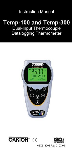
Instruction <strong>Manual</strong><br />
<strong>Temp</strong>-100 and <strong>Temp</strong>-<strong>300</strong><br />
Dual-Input <strong>Thermocouple</strong><br />
<strong>Datalogging</strong> <strong>Thermometer</strong><br />
68X518203 Rev 0 07/09
TABLE OF CONTENTS<br />
1. INTRODUCTION ....................................... 1<br />
2. SAFETY PRECAUTIONS.......................... 2<br />
3. SPECIFICATIONS .................................... 3<br />
4. BATTERY INSTALLATION AND<br />
REPLACEMENT........................................ 6<br />
5. INSERTING AND REMOVING OPTIONAL<br />
RUBBER ARMOUR................................... 7<br />
6. ASSEMBLING OPTIONAL HANDSFREE<br />
ACCESORIES ........................................... 8<br />
7. CONNECTING A THERMOCOUPLE........ 9<br />
8. KEY FUNCTIONS ................................... 11<br />
9. DISPLAY OVERVIEW ............................. 12<br />
10. MEASUREMENT MODE ......................... 13<br />
11. HOLD FUNCTON .................................... 14<br />
12. MIN, MAX, and AVE FUNCTION............. 14<br />
13. DATA LOGGING ..................................... 14<br />
14. SETUP MODE ......................................... 15<br />
15. GENERAL SETUP SCREEN .................. 16<br />
16. CALIBRATION SCREEN ......................... 18<br />
17. ALARMS SCREEN .................................. 21<br />
18. DATA LOGGING SCREEN ..................... 22<br />
19. CALIBRATION REPORT SCREEN ......... 23<br />
20. CLEAR / RESET SCREEN ..................... 24<br />
21. MAINTENANCE....................................... 25<br />
22. CLEANING............................................... 25<br />
23. BATTERIES ............................................. 25<br />
24. TROUBLE SHOOTING............................ 26<br />
25. ACCESSORIES ....................................... 27<br />
26. WARRANTY ............................................ 28<br />
27. PRODUCT RETURN ............................... 28<br />
28. INNOCAL® CALIBRATION AND REPAIR<br />
SERVICES............................................... 29
1. INTRODUCTION<br />
This versatile hand-held<br />
instrument provides highly<br />
accurate temperature<br />
measurements. The<br />
instrument is designed<br />
for easy operation and<br />
includes the following<br />
features:<br />
• Menu driven setup and operation<br />
• <strong>Datalogging</strong> for up to 1000 points on<br />
<strong>Temp</strong> 100, 2000 on <strong>Temp</strong> <strong>300</strong><br />
• USB output (<strong>Temp</strong> <strong>300</strong> only)<br />
• Differential temperature<br />
measurements<br />
• Operator selection of Celsius or<br />
Fahrenheit scale<br />
• Resolution of 0.1° C/F from -199.9 to<br />
999.9°<br />
• Large backlit LCD with two lines of<br />
four-digit display<br />
• Hold feature for temporarily retain a<br />
reading<br />
• Displays min and max readings<br />
• Field calibration capability<br />
• Disabling of Auto-Off function<br />
• Low battery warning<br />
• Two blade female ANSI miniconnector<br />
input<br />
• Operates with a wide selection of<br />
probes<br />
- 1 -
2. SAFETY PRECAUTIONS<br />
WARNING:<br />
1. This instrument is designed to<br />
accept low level signals supplied by<br />
standard <strong>Thermocouple</strong>s. Under NO<br />
circumstances should the input<br />
voltage exceed the specified 50V<br />
RMS.<br />
2. To prevent ignition of a hazardous<br />
atmosphere, batteries must only be<br />
changed in an area known to be<br />
non-hazardous.<br />
CAUTION:<br />
1. Do not use or store this instrument in<br />
microwave ovens or any abnormally<br />
hot or cold areas.<br />
2. Weak batteries should not be left in<br />
the instrument. Dead batteries can<br />
leak and cause damage to unit.<br />
DANGER:<br />
1. Voltages present at the<br />
<strong>Thermocouple</strong> may also be present<br />
at the battery terminals. Always<br />
disconnect the <strong>Thermocouple</strong> when<br />
changing batteries.<br />
- 2 -
3. SPECIFICATIONS<br />
<strong>Thermocouple</strong> <strong>Thermometer</strong>s<br />
Type<br />
Type J<br />
Type K<br />
Type T<br />
Type E<br />
Type R (<strong>300</strong> only)<br />
Type S (<strong>300</strong> only)<br />
Type N (<strong>300</strong> only)<br />
Type B (<strong>300</strong> only)<br />
<strong>Temp</strong>erature range<br />
–210°C to 1200°C<br />
(–346°F to 2192°F)<br />
–250°C to 1372°C<br />
(–418°F to 2501°F)<br />
–250°C to 400°C<br />
(–418°F to 752°F)<br />
-250°C to 1000°C<br />
(-418°F to1832°)<br />
0°C to 1768°C<br />
(32°F to 3214°F)<br />
0°C to 1768°C<br />
(32°F to 3214°F)<br />
-250°C to 1<strong>300</strong>°C<br />
(-418°F to 2372°F)<br />
200°C to 1800°C<br />
(392°F to 3272°F)<br />
Out of range display: - - - -<br />
Resolution<br />
0.1°/1° auto-ranging,<br />
0.1° C/F from -199.9 to 999.9°,<br />
1° outside this range<br />
- 3 -
Accuracy<br />
J,K,T,E & N<br />
Below -150 °C (-238 °F):<br />
±0.25% of reading ±1 °C (±0.25% ±0.7 °F)<br />
Above -150 °C (-238 °F):<br />
±0.1% of reading ±0.4 °C (±1% ±0.7 °F)<br />
R,S & B<br />
±0.1% of reading ±1 °C (±0.1% ±2 °F)<br />
Display<br />
Backlit Dot-matrix 50mm X 37.2mm<br />
Data Logging<br />
<strong>Temp</strong> 100 : 1000 points<br />
<strong>Temp</strong> <strong>300</strong> : 2000 points<br />
Logging Interval<br />
1 sec to 60 min<br />
Min/Max/Avg Function<br />
Yes<br />
Auto Off (adjustable time)<br />
Enable/Disable option available<br />
Stability Criteria<br />
Yes, upon stability of 5 seconds<br />
Display update rate<br />
0.6 sec per update.<br />
Input<br />
Two thermocouple with ANSI connector.<br />
Input Protection<br />
50V rms<br />
- 4 -
Storage<br />
–40°C to 65°C (–40°F to 149°F)<br />
Humidity<br />
10% to 90% (non-condensing)<br />
Battery Life<br />
Size: Three AA, 1.5V; Alkaline<br />
Life: 400 hours continuous, typical,<br />
(without backlighting)<br />
Dimensions<br />
Without Armor:<br />
175mm (L) X 97mm (W) X 42mm (H)<br />
With Armor:<br />
180mm (L) X 102mm (W) X 52mm (H)<br />
Weight with batteries<br />
Without Armor: 267g<br />
With Armor: 362g<br />
Ingress protection:<br />
Meets IEC-529 IP-54 for dust and water<br />
resistant enclosures (probe attached)<br />
CE Compliance<br />
EN61326-1/A1: 1998 (EU EMC Directive)<br />
- 5 -
4. BATTERY INSTALLATION AND<br />
REPLACEMENT<br />
The total battery life without<br />
backlighting and alarm is about 400<br />
hours. The battery bar annunciator<br />
represents the battery strength. An<br />
empty battery annunciator indicates low<br />
battery strength; a blinking battery<br />
annunciator indicates that the batteries<br />
should be replaced immediately.<br />
Selected settings are stored in memory<br />
and will remain in memory even after<br />
power is turned off, or while batteries<br />
are being replaced.<br />
1. Before changing battery, turn<br />
instrument off and disconnect<br />
thermocouple.<br />
2. Loosen screw and lift battery cover off<br />
back of case.<br />
3. Remove the three AA batteries.<br />
4. Insert three new batteries observing<br />
polarity.<br />
5. Install cover and tighten screw.<br />
- 6 -
5. INSERTING AND REMOVING<br />
OPTIONAL RUBBER ARMOUR<br />
1. To insert thermometer into the<br />
optional rubber armor, slide in from<br />
the top of meter before pushing the<br />
bottom edges of meter down to set it<br />
into position. Lift up the stand at the<br />
back of meter for bench top<br />
applications if necessary.<br />
2. To remove thermometer from armor,<br />
push out from the bottom edges of<br />
meter until it is completely out of boot.<br />
- 7 -
6. ASSEMBLING OPTIONAL<br />
HANDSFREE ACCESORIES<br />
You can use the optional magnets and<br />
strap in the Handsfree Kit accessories for<br />
hands free operations.<br />
- 8 -
7. CONNECTING A THERMOCOUPLE<br />
Use the correct thermocouple type for<br />
your instrument setting. Using an<br />
incorrect thermocouple type will result in<br />
erroneous readings. <strong>Thermocouple</strong>s are<br />
colour coded by type using the North<br />
American ANSI Colour Code as follows:<br />
TYPE COLOR<br />
J Black<br />
K Yellow<br />
T Blue<br />
E Purple<br />
<strong>Thermocouple</strong> connectors have one wide<br />
blade and one narrow blade. Do not force<br />
connector in backwards. Connect<br />
thermocouples to receptacles at top of<br />
instrument as shown in the following<br />
illustration.<br />
- 9 -
<strong>Thermocouple</strong> wiring polarity must be<br />
correct. If readings decrease as the<br />
temperature increases, the thermocouple<br />
wires may be reversed. The red wire is<br />
negative for thermocouple wires<br />
manufactured in North America.<br />
If no probe is connected the display will<br />
read “open”.<br />
<strong>Thermocouple</strong>s are sensitive at the tip or<br />
measuring junction. When taking<br />
measurements, allow time for the reading<br />
to stabilize. Multiplying the time constant<br />
of the probe by 5 will give you the<br />
approximate time required.<br />
- 10 -
8. KEY FUNCTIONS<br />
F1<br />
F2<br />
F3<br />
hold<br />
on/off<br />
light<br />
recall▲<br />
log▼<br />
Step through Min, Max and<br />
Avg readings.<br />
Choose probe T1, T2 or T1-T2<br />
Toggle between menu and<br />
measure mode<br />
Freeze display<br />
Turns meter on and off (press<br />
and hold for 3 seconds to turn<br />
off)<br />
Press momentarily to turn on<br />
backlight<br />
Recalls and steps through<br />
stored readings<br />
Stores current measured<br />
value to memory<br />
Note: Function keys change in setup<br />
mode to provide advanced operation<br />
flexibility. Text above key will indicate<br />
function.<br />
- 11 -
9. DISPLAY OVERVIEW<br />
1 2<br />
3<br />
7<br />
6<br />
5<br />
4<br />
The dot matrix display features a large<br />
primary display, smaller secondary<br />
displays for channel info or min/max/ave,<br />
and helpful annuciators for added<br />
measurement data<br />
1 HOLD - Active<br />
2 Data Logging is Active<br />
3 Alarm Enabled – channel in alarm<br />
indicated: T1 or T2 or T1&T2<br />
4 MAX/MIN/AVG of Secondary<br />
channel if MIN/MAX/AVG activated<br />
5 MAX/MIN/AVG of Primary channel<br />
if MIN/MAX/AVG activated<br />
6 Min/Max hit time since Min/Max<br />
activated. For Avg, it is continually<br />
increments since activated<br />
7 Current active Mode –<br />
Min/Max/Avg<br />
- 12 -
10. MEASUREMENT MODE<br />
On initial start-up the meter will display<br />
the measured value for input one in the<br />
primary display and for input two in the<br />
secondary display.<br />
Pressing the F2 key will toggle primary<br />
display through input one (T1), input two,<br />
and the delta (T1 – T2) values.<br />
Pressing the F1 key initiates and toggles<br />
through Minimum, Maximum, and<br />
Average reading modes.<br />
Pressing F3 enter accesses Setup mode.<br />
- 13 -
11. HOLD FUNCTON<br />
Press the hold key to retain the reading<br />
on the display. Press the hold key again<br />
for normal operation.<br />
12. MIN, MAX, and AVE FUNCTION<br />
Press the F1 key to toggle between the<br />
minimum, maximum, and average<br />
readings. The minimum and maximum<br />
reading function is ideal for monitoring<br />
unattended operations while continually<br />
displaying every temperature change that<br />
occurs. The minimum and maximum<br />
values are sensed and automatically<br />
stored.<br />
To exit and clear this function, press the<br />
F3 to access the Menu functions.<br />
See the Clear Reset menu section for<br />
more details.<br />
13. DATA LOGGING<br />
Press the log ▼ key to store the current<br />
reading to memory. The memory<br />
indicator M = 1234 shows the memory<br />
location for the next stored reading.<br />
Press the recall ▲ key to review stored<br />
readings.<br />
See section on Data Logging for timed<br />
logging, and logging to a computer (<strong>300</strong><br />
model only).<br />
See section on Clear/Reset for<br />
information on clearing stored readings.<br />
- 14 -
14. SETUP MODE<br />
To access the setup mode from<br />
measurement mode press the F3 key<br />
(Menu).<br />
Press ▲▼ keys on the meter key pad to<br />
scroll through options.<br />
To enter a setup screen press Select F1<br />
key.<br />
To return to measurement mode press<br />
Meas F3 key. Following menu options<br />
are listed<br />
1. General Setup<br />
2. User field calibration<br />
3. Alarm settings<br />
4. Data logging settings<br />
5. View user calibration report<br />
6. Clear/Reset options<br />
- 15 -
15. GENERAL SETUP SCREEN<br />
The first page of the General Setup<br />
screens let you set probe type,<br />
measurement units, time, and date.<br />
Press F1 to indicate you want to change<br />
the setting of the current parameter or<br />
recall▲ or log▼ to move to the next<br />
parameter.<br />
Press recall▲ or log▼ to change the<br />
options.<br />
Press F2 to choose the next setting.<br />
Whenever set the options, press F1 for<br />
accepting the choice.<br />
- 16 -
On the second page you can set auto-off<br />
time, line frequency, and password.<br />
This screen below is used to reset/change<br />
password. In the event if uses forget<br />
his/her password, 5586 can be used to<br />
reset to a new value<br />
- 17 -
16. CALIBRATION SCREEN<br />
The thermometer is factory calibrated and<br />
does not require calibration before use.<br />
The Calibration function allows single<br />
point calibration of the thermometer, at<br />
0°C (32°F) to compensate for<br />
thermocouple off-set error. It is NOT<br />
necessary to perform a field calibration to<br />
obtain specified meter accuracy. Use the<br />
field calibration feature to improve<br />
thermometer/probe accuracy or to<br />
compensate for thermocouple drift...<br />
Before go into the calibration mode, must<br />
enter the password. Press F2 to change to<br />
the next digit. (Default Password is 9900)<br />
There are three calibration options:<br />
Offset – adjusts at a single point<br />
Slope – adjusts at two points<br />
Match – adjusts readings on T1 to match<br />
those on T2. Or adjusts T2 to match T1.<br />
- 18 -
Select calibration method by pressing F1<br />
and the▲ or ▼ keys. Then select the<br />
channel you with to calibrate the▲ or ▼<br />
keys.<br />
Offset Calibration<br />
Use the ▲ or ▼ keys to adjust the value to<br />
match known temperature standard. Press<br />
F1 to accept.<br />
- 19 -
Slope Calibration<br />
Use the ▲ or ▼ keys to adjust the value to<br />
match known temperature standard. .<br />
Press F1 to accept. Then move to second<br />
temperature point using the ▲ or ▼ keys<br />
and repeat.<br />
Match Calibration<br />
Use the ▲ or ▼ keys to adjust the value to<br />
match T1 readings and T2 readings.<br />
- 20 -
17. ALARMS SCREEN<br />
Disable or enable the alarm for individual<br />
probe by pressing recall▲ or log▼and F1<br />
to accept. Increase or decrease individual<br />
limit by pressing recall▲ or log▼.<br />
- 21 -
18. DATA LOGGING SCREEN<br />
Press recall▲ or log▼to choose the<br />
logging methods as auto or manual. If it is<br />
auto logging, using recall▲ or log▼to set<br />
time interval. Its range is from 0min to<br />
60min.<br />
Button “Page1” will appear only in <strong>Temp</strong><br />
<strong>300</strong>.<br />
Data Transfer from Meter to Computer<br />
Model <strong>300</strong> only.<br />
Please refer to softcopy of the driver<br />
manual in the CD for installation and<br />
datalogging instructions<br />
- 22 -
Once the USB connection is establish with<br />
PC, press the Start button to download<br />
data from Meter to PC using<br />
HyperTerminal.<br />
19. CALIBRATION REPORT SCREEN<br />
The Calibration report will show the time<br />
and date along with results of the last user<br />
calibration.<br />
- 23 -
20. CLEAR / RESET SCREEN<br />
Press F1 to choose which data you want<br />
to clear or reset. For calibration, logged<br />
data and reset all, you will have to enter<br />
the password to proceed. (Default<br />
Password is 9900)<br />
- 24 -
21. MAINTENANCE<br />
Properly used, the thermometer should<br />
maintain calibration indefinitely and not<br />
require service other than occasional<br />
cleaning of the housing and changing of<br />
the batteries.<br />
22. CLEANING<br />
WARNING:<br />
TO PREVENT IGNITION OF A<br />
HAZARDOUS ATMOSPHERE BY<br />
ELECTROSTATIC DISCHARGE,<br />
CLEAN WITH DAMP CLOTH.<br />
Do not clean with abrasives or solvents.<br />
Use mild detergents, never immerse nor<br />
use excessive fluid.<br />
23. BATTERIES<br />
If there is no display when the<br />
thermometer is turned on, check condition<br />
of the three AA batteries. Also check that<br />
the battery terminals are clean and<br />
batteries are properly installed. If<br />
replacement is necessary, refer to the<br />
BATTERY INSTALLATION AND<br />
REPLACEMENT section for replacement<br />
procedure.<br />
- 25 -
24. TROUBLE SHOOTING<br />
The following chart lists the most probable<br />
faults. There are no internal adjustments<br />
or user-replaceable parts.<br />
FAULT<br />
ACTION<br />
NO<br />
Display<br />
Check condition of batteries.<br />
Check that batteries are inserted<br />
properly.<br />
Display<br />
shows<br />
- - - -<br />
Out of range indication<br />
Display<br />
Shows<br />
OPEN<br />
No thermocouple connected in the<br />
Connector<br />
Display<br />
Shows<br />
Err<br />
If display shows this message<br />
other than during the field<br />
calibration mode, please return the<br />
instrument for servicing<br />
- 26 -
25. ACCESSORIES<br />
Replacement Meters and Meter<br />
Accessories<br />
Item <strong>Oakton</strong> Thermo Scientific<br />
Type 100 thermometer 91427-40 TSTEMP100<br />
Type <strong>300</strong> thermometer 91427-50 TSTEMP<strong>300</strong><br />
Rubber Armour with Stand 35427-80 ARMORTEMP<br />
Handsfree Kit (Two Magnets<br />
and a Strap)<br />
General purpose probe<br />
(immersion Into liquids), type<br />
J<br />
Penetration probe (meat,<br />
semi-soft Materials), type J<br />
Surface probe<br />
(direct contact on<br />
Hot surfaces), type J<br />
Clip-on probe (surface<br />
contacts- Electronics), type J<br />
General purpose probe<br />
(immersion Into liquids), type<br />
K<br />
Penetration probe (meat,<br />
semi-soft Materials), type K<br />
Surface probe<br />
(direct contact on<br />
Hot surfaces), type K<br />
Clip-on probe (surface<br />
contacts- Electronics), type<br />
K<br />
35427-85 HNDSFRKIT<br />
08517-55 EC-TPGLPJ-<br />
01M<br />
08517-65 EC-TPPENJ-<br />
01M<br />
08517-60 EC-TPSURJ-<br />
01M<br />
08469-00 EC-TPCLPJ-<br />
01M<br />
08516-55<br />
EC-TPGLPK-<br />
01M<br />
08516-65 EC-TPPENK-<br />
01M<br />
08516-60 EC-TPSURK-<br />
01M<br />
08469-02 EC-TPCLPK-<br />
01M<br />
- 27 -
26. WARRANTY<br />
The Manufacturer warrants this product<br />
to be free from significant deviations<br />
from published specifications for a<br />
period of three years. If repair or<br />
adjustment is necessary within the<br />
warranty period, the problem will be<br />
corrected at no charge if it is not<br />
due to misuse or abuse on your part<br />
as determined by the Manufacturer.<br />
Repair costs outside the warranty<br />
period, or those resulting from product<br />
misuse or abuse, may be invoiced to<br />
you.<br />
27. PRODUCT RETURN<br />
To limit charges and delays, contact the<br />
seller or Manufacturer for authorization<br />
and shipping instructions before<br />
returning the product, either within or<br />
outside of the warranty period. When<br />
returning the product, please state the<br />
reason for the return. For your<br />
protection, pack the carefully and insure<br />
it against possible damage or loss. The<br />
Manufacturer will not be responsible for<br />
damage resulting from careless or<br />
insufficient packing.<br />
- 28 -
28. INNOCAL® CALIBRATION AND<br />
REPAIR SERVICES<br />
Optimum performance of your<br />
temperature-measuring instrument is not<br />
a timeless condition. To ensure quality<br />
measurements, have your instrument<br />
calibrated regularly. Trust InnoCal® to<br />
satisfy your calibration and equipment<br />
repair needs. With over a decade of<br />
service, we've helped thousands of<br />
customers meet ISO, FDA, EPA,<br />
GLPs/cGMPs and other quality<br />
standards.<br />
Conformity*<br />
ISO/IEC 17025:2005 accredited<br />
NIST Handbook 150, 2000 Edition<br />
ANSI/NCSL Z540-2-1997<br />
NIST Technical Note 1297<br />
ISO 9000:2000<br />
Fast Service<br />
Our substantial inventory of replacement<br />
parts ensures a fast turnaround and<br />
prevents costly downtime. Most<br />
instruments serviced in five business<br />
days!<br />
Excellent Value<br />
Get quality at a fair price. Our InnoCal®<br />
NIST-traceable certificates offer<br />
extensive test data on a broad range of<br />
measurement parameters without<br />
breaking the bank!<br />
- 29 -
Reliable Support<br />
Trust in our free diagnostic support and<br />
troubleshooting advice. Our factorytrained<br />
metrologists and technicians are<br />
armed with years of experience and<br />
extensive technical data.<br />
Convenient Reminders<br />
It’s so easy to keep your instruments<br />
functioning properly. Based on your<br />
requirements, InnoCal will send you a<br />
reminder when it’s time to re-certify or<br />
service your instrument.<br />
We provide you with the documentation<br />
you need to meet your most stringent<br />
quality requirements for the control of<br />
inspection, measuring, and test<br />
equipment.<br />
Certification includes certificate of<br />
calibration with test data, including:<br />
● description and identification of the<br />
item certified<br />
● condition of the item<br />
● issue date<br />
● identification of calibration procedure<br />
● calibration date<br />
● as found/as left test data (where<br />
applicable)<br />
● signature of technician<br />
● statement of estimated uncertainty<br />
● list of equipment used to perform<br />
calibration (including their calibration<br />
dates)<br />
- 30 -
With today's high quality standards such<br />
as ISO 9000, certification is becoming<br />
increasingly important. Traceability is not<br />
a timeless condition. It must be verified<br />
and maintained over the life of the<br />
calibration to ensure the highest<br />
accuracy possible. When you have your<br />
calibration done by InnoCal, we will send<br />
you an automatic reminder when it is<br />
time to recalibrate your instrument.<br />
Are your calibration certificates good<br />
enough<br />
InnoCal surpasses the competition by<br />
providing the most complete certificates<br />
as required by NIST. All of our<br />
certificates include measured data and<br />
point-by-point measurement uncertainty,<br />
and by request, we’ll provide test<br />
accuracy and test uncertainty ratios at<br />
no extra cost. Call us today and see why<br />
InnoCal is The Choice of Quality.<br />
* See our Scope of Accreditation for any<br />
limitations.<br />
- 31 -
TECHNICAL ASSISTANCE<br />
If you have any questions about the use<br />
of this product, contact the<br />
Manufacturer or authorized seller.<br />
For more information on OAKTON<br />
Instruments Products, please contact<br />
your nearest distributor or visit our web<br />
site listed below:<br />
OAKTON Instruments<br />
P.O. Box 5136<br />
Vernon Hills, IL 60061, USA Tel (in U.S.):<br />
888-462-5866<br />
Tel (outside U.S.) 1-847-549-7600<br />
Fax: (1) 847-247-2984<br />
Website: www.4oakton.com<br />
E-mail: info@oakton.com<br />
Distributed by: