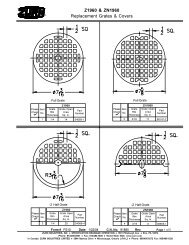
Model 950XL Model 975XL - Zurn
Model 950XL Model 975XL - Zurn
Model 950XL Model 975XL - Zurn

You also want an ePaper? Increase the reach of your titles
YUMPU automatically turns print PDFs into web optimized ePapers that Google loves.
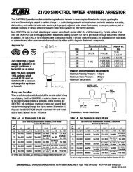
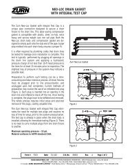
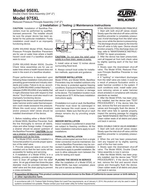
<strong>Model</strong> <strong>950XL</strong>Double Check Valve Assembly (3/4"-2")<strong>Model</strong> <strong>975XL</strong>Reduced Pressure Principle Assembly (1/4"-2")CAUTION: Installation of Backflow Preventersmust be performed by qualified,licensed personnel. The installer shouldbe sure the proper device has been selectedfor the particular installation. Faultyinstallation could result in an improperlyfunctioning device.ZURN WILKINS <strong>Model</strong> <strong>975XL</strong> ReducedPressure Principle Backflow Preventersare for use on water lines where a healthhazard could exist if a backflow situationwere to occur.ZURN WILKINS <strong>Model</strong> <strong>950XL</strong> DoubleCheck Valve assemblies are for use onwater lines where a health hazard does notexist in the event of a backflow situation.Proper performance is dependent uponfollowing these installation instructions andprevailing governmental and industry standardsand codes. Failure to do so, accordingto ZURN WILKINS Limited Warranty "...releases ZURN WILKINS of any liability thatit might otherwise have with respect to thatdevice." Such failure could also result in animproperly functioning device.Damage to the device could result whereverwater hammer and/or water thermal expansioncould create excessive line pressure.Where this could occur, shock arrestersand/or pressure relief valves should beinstalled downstream of the device.1. Before installing either a <strong>Model</strong> <strong>975XL</strong>or <strong>Model</strong> <strong>950XL</strong> Backflow Preventer, flushthe line thoroughly to remove all debris,chips and other foreign matter. If required,a strainer should be placed upstream ofthe Backflow Preventer. CAUTION: Do notuse a strainer in seldom used emergencywaterlines such as fire lines.2. The <strong>Model</strong> <strong>975XL</strong> must be installed in ahorizontal position to provide proper operationof the relief valve.3. Provide adequate space around theinstalled unit so that the test cocks will beaccessible for testing and servicing.4. If installation of a <strong>Model</strong> <strong>975XL</strong> is in abuilding, provide a suitable drain arrangementto drain off spillage from the reliefvalve. An air gap at least two times the pipediameter must be provided between therelief valve and the drain piping to preventa cross-connection. Installation Testing Maintenance InstructionsOPTIONALWATER METERPROTECTIVEENCLOSUREINLET SHUT-OFFAIR GAPCAUTION: Do not pipe the relief valvesolidly to a floor drain, sewer or sump.5. Install valve at least 12 inches abovesurrounding flood level.6. Always consult local codes for installationmethods, approvals and guidance.OUTDOOR INSTALLATION<strong>Model</strong> <strong>975XL</strong> and <strong>Model</strong> <strong>950XL</strong> BackflowPreventers may be installed outdoors onlyif the device is protected against freezingconditions. Exposure to freezing conditionswill result in improper function or damageto the device. The installation location mustbe kept above 32°F. All the basic installationinstructions apply.If installation is in a pit or vault, the BackflowPreventer must never be submerged inwater because this could cause a crossconnection.Make sure that the pit or vaultalways remains dry by providing ampledrainage.INDOOR INSTALLATIONIndoor installation is preferred in areas thatare subject to freezing conditions. All thebasic installation instructions apply to suchinstallations.PARALLEL INSTALLATIONWhere uninterrupted service from a singlemeter connection must be maintained, twoor more Backflow Preventers may be connectedin parallel. All the basic installationinstructions apply to parallel installation. Besure to allow adequate room between theunits for testing and repair.PLACING THE DEVICE IN SERVICEAfter the installation of a <strong>Model</strong> <strong>975XL</strong> or<strong>Model</strong> <strong>950XL</strong> has been completed, placethe unit in service as follows:<strong>975XL</strong> REDUCED PRESSURE PRINCIPLE1. Start with both shut-off valves closed.Slowly open the inlet shut-off valve until thebackflow preventer is completely pressurized.A brief discharge from the relief valvemay occur while the device is pressurizing.The discharge should cease by the time theshut-off valve is fully open. Device shouldfunction properly. If the discharge does notstop, refer to "MAINTENANCE INSTRUC-TIONS" for repair procedures.2. After the device has been pressurized,vent all trapped air from both check valveby slightly opening each of the four testcocks.3. Slowly open the downstream shut-offvalve. The <strong>Model</strong> <strong>975XL</strong> Reduced PressurePrinciple Backflow Preventer is nowin service.4. If "spitting" or intermittent dischargesfrom the relief valve are noted, it could bea result of pressure fluctuation and/or awater hammer condition in the system. Ifsuch conditions exist, install water pressurereducing valves or water hammershock arresters in compliance with industrystandards as needed.5. After the <strong>Model</strong> <strong>975XL</strong> has been properlyinstalled, test the device (see "TESTPROCEDURES"). If the device fails thetest, remove the first and second checkvalves and thoroughly flush the device. Ifthe relief valve fails to operate properly,inspect the sensing passage for clogging(see "MAINTENANCE INSTRUCTIONS").Clean rubber seals of all debris and placeunit back in service.<strong>950XL</strong> DOUBLE CHECK VALVE ASSEMBLY1. Start with both shut-off valves closed.Slowly open the inlet shut-off valve until thebackflow preventer is completely pressurized.2. When the unit has been pressurized,vent any trapped air by slightly openingeach of the four test cocks.3. Slowly open the downstream shut-offvalve. The <strong>Model</strong> <strong>950XL</strong> Double CheckValve assembly is now in service.4. After the <strong>Model</strong> <strong>950XL</strong> has been properlyinstalled, test the device (see "TESTPROCEDURES"). If the device fails thetest, remove the first and second checkvalves and thoroughly flush the device.Clean rubber seats of all debris and placeunit back in service.Proposition 65 Warning This product contains chemicals known to the State of California to cause cancer or birth defectsor other reproductive harm.DRAINDIRECTION OF FLOWIn accordance with U.S. Federal Safe Drinking Water Act Lead-Free requirements, as of January 4, 2014, this product can only be used in watersystems considered non-potable. Please contact your local water utility for further requirements.12" MIN30" MAX®
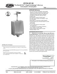
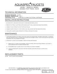
Testing ProceduresMODEL <strong>950XL</strong> DOUBLE CHECK VALVE ASSEMBLYEquipment Required: Differential pressure gauge test kit.<strong>950XL</strong> TEST NO. 1Purpose:Test #1 check valve for drip tightness against reverse flow.Requirement:The valve must close tight against reverse flow under all pressuredifferentials.Procedure:1. Close #2 and #1 shut-off valves.2. Open test cocks #2 and #3.3. Attach "VENT" hose to test cock #1, the "LOW" hose to testcock #2 and the "HIGH" hose to test cock #3.4. Open by-pass valves "A" and "C", then open test cock #1.5. Open test cock #4 to bleed air from valve and test kit.6. Close by-pass valve "C". Slowly open by-pass valve "B" untildifferential gauge reads 5 PSID. Close by-pass valve "B".7. The #1 check valve is considered tight if differential pressureis maintained.MODEL <strong>975XL</strong> REDUCED PRESSURE PRINCIPLEASSEMBLYEquipment Required: Differential pressure gauge test kit.<strong>975XL</strong> TEST NO. 1Purpose:Test #2 check valve for tightness against reverse flow.Requirement:The valve must close tight against reverse flow under all pressuredifferentials.Procedure:1. Attach the "HIGH" hose to test cock #2 and the "LOW" hoseto test cock #3.2. Close #2 shut-off valve.3. Open test cocks #2 and #3.4. Open by-pass valves "C" and "A" and bleed to atmosphereuntil all air is expelled.5. Close by-pass valve "A". Open by-pass valve "B" and bleedto atmosphere until all air is expelled. Close by-pass valves"B" and "C".6. Attach the "VENT" hose to test cock #4.7. Slowly open by-pass valves "A" and "C" and keep by-passvalve "B" closed.8. Open test cock #4.9. Indicated pressure differential will drop slightly. If pressuredifferential does not continue to decrease, the #2 checkvalve is considered tight.<strong>975XL</strong> TEST NO. 2Purpose:Test #1 check valve for tightness and record pressure drop across#1 check valve.Requirement:The static pressure drop across #1 check valve shall be greater thanthe relief valve opening point (test #3), and at least 5.0 psid.Procedure:1. Close by-pass valve "A"2. Close test cock #4, and disconnect "VENT" hose from test cock#4.3. Open by-pass valves "B" and "C" bleeding to atmosphere,then close by-pass valve "B" restoring the system to normal staticcondition.4. Observe the pressure differential gauge and note this as the#1 check valve psid.2ZURN WILKINS1747 Commerce Way, Paso Robles, CA 93446 Phone:855-663-9876 Fax:805-238-5766www.zurn.com<strong>950XL</strong> TEST NO. 2Purpose:Test #2 check valve for tightness against reverse flow.Requirement:The valve must close tight against reverse flow under all pressuredifferentials.Procedure:1. Close test cock #1.2. Attach "HIGH" hose to test cock #4 and "LOW" hose to testcock #3.3. Open by-pass valve "C". Open test cocks #1 and #4.4. Repeat step #6 of TEST NO. 1.5. The #2 check valve is considered tight if differential pressureis maintained.#4 TEST COCK#2 SHUT-OFFVALVEBY-PASSVALVE "A"HIGH SIDE HOSE#3 TEST COCK#2 TEST COCKBY-PASSVALVE "C"BY-PASSVALVE "B"VENT HOSE#1 TEST COCK#1 SHUT-OFFVALVELOW SIDE HOSE<strong>975XL</strong> TEST NO. 3Purpose:To test operation of the differential relief valve.Requirement:The pressure differential relief valve must operate to maintain the"ZONE" between the two check valves at least 2 PSID less thanthe supply pressure.Procedure:1. Close by-pass valve "C" and open by-pass valve "A".2. Open by-pass valve "B" very slowly until differential gaugeneedle starts to drop. Hold the valve at this position andobserve the gauge reading at the moment the first dischargeis noted from the relief valve. Record this as the openingdifferential pressure of the relief valve.#3 TEST COCK#4 TEST COCK#2 SHUT-OFFVALVE#2 CHECK VALVEBY-PASSVALVE "A"HIGH SIDE HOSE#1 CHECK VALVE#2 TEST COCK#1 TEST COCK#1 SHUT-OFFVALVEBY-PASSVALVE "C"BY-PASSVALVE "B"VENT HOSELOW SIDE HOSE®
Maintenance InstructionsAll <strong>Model</strong> <strong>975XL</strong> Reduced Pressure Principle Backflow Preventersmust be inspected and maintained by licensed personnel atleast once a year or more frequently as specified by local codes.Replacement of worn or damaged parts must only be made withgenuine "ZURN WILKINS" parts. The ZURN WILKINS Certificateof Limited Warranty provides that failure to do so "...releasesZURN WILKINS of any liability that it might otherwise have withrespect to that device." Such failure could also result in an improperlyfunctioning device.The <strong>Model</strong> <strong>975XL</strong> Reduced Pressure Principle Assemblies shouldbe thoroughly flushed after backflow conditions occur to preventany type of corrosive deterioration to its components. Failure todo so could result in malfunction of the device.GENERAL MAINTENANCE1. Clean all parts thoroughly with water after disassembly.2. Carefully inspect rubber seal rings, diaphragms and o-ringsfor damage.3. Test unit after reassembly for proper operation (see "TestingProcedures").SERVICING CHECK VALVES1. Close inlet and outlet shut-off valves.2. Open No. 2, No. 3 and No. 4 test cocks to release pressurefrom valve.3.Unscrew check valve covers using appropriate size wrench(CAUTION: Cover is spring loaded). To avoid injury, hold coverdown firmly with one hand while unscrewing.4. Remove check valve cover, spring and poppet assembly.5. Inspect the rubber seal ring for cuts or embedded debris. Toremove seal ring, remove screw and seal ring retainer. If thereverse side of the seal ring is unused, it is possible to invert theseal ring. This would be considered a temporary solution to fixinga fouled check and should be replaced with a new seal ring assoon as possible.6. Inspect valve cavity and seating area. Remove any debris.7. If installed with removable seat, unscrew seat from body andreplace with new seat and lightly grease o-ring.*8. Reverse the above procedures to reinstall check valve assembly.Care should be taken to make sure the heavy spring is installed inthe No. 1 check valve. For the 3/4"-1" <strong>975XL</strong>SE the No. 2 poppethas a cupped seal retainer. For the 1 1/4"-2" <strong>975XL</strong>SE the No. 1seat has a taller seat profile than the No. 2 seat.SERVICING RELIEF VALVE1. Remove relief valve cover bolts and cover. Gently pull on diaphragmto remove the cartridge assembly.2. Inspect seal ring for cuts and embedded debris. Turn over orreplace if required.3. Disassemble cartridge by unscrewing relief valve retaining screw.4. Inspect diaphragm and o-rings for damage. Replace requiredparts and apply a light coat of grease to plunger o-ring.5. Carefully reassemble cartridge assembly.6. Inspect relief valve seat for wear on seating surface. If damaged,replace seat and seat o-ring.*7. Insert cartridge assembly into relief valve body.8. Replace relief valve cover and cover bolts.9. Place device in service and test per "TESTING PROCEDURES".*For seat removal assistance, consult factory.RETAINING SCREW(CHECK)SEAT(CHECK)SEAL RING RETAINER(CHECK)SPRING(CHECK)COVER(CHECK)RELIEF VALVE COVERCOVER BOLTSDIAPHRAGMSEAT (RELIEF VALVE)SPRING(RELIEF VALVE)SEAL RING(RELIEF VALVE)TroubleshootingWhen the relief valve discharges intermittently it can be almost always assumed that the device is functioning correctly and that thedischarge is caused by systems such as inlet pressure fluctuations or water hammer due to quick closing valves.PROBLEM1. SUDDEN OR RAPID SPITTING2. LIGHT INTERMITTENT DRIPPOPPETSEAL RING(CHECK)O-RING(COVER)POSSIBLE CAUSESCORRECTIVE ACTION1. Drop in inlet pressure.A. Install an in-line spring loaded check2. Sudden increase in downstream pressure valve upstream of backflow.due to water hammer from quick closing B. Install pressure reducing valve upstreamshut-off valve installed downstream. of backflow unit.C. Install in-line spring loaded check valvedownstream of backflow as close to sourceas possible, but not closer that 4 feet.1. Slightly fouled #1 check.A. Clean #1 check and turn check valveseal ring over or replace.Continuous discharge of the relief valve signifies a failure of some part of the device. To help determine the specific area of failure, closethe #2 shut-off valve. If the discharge stops, the #2 check requires service. If the discharge continues, the #1 check requires service.1. CONTINUOUS DISCHARGE 1. Fouled #1 check.2. Fouled relief valve seat.3. Fouled #2 checkO-RING(PLUNGER)PLUNGER(UPPER)PLUNGER(LOWER)SEAL RING RETAINER(RELIEF VALVE)RETAINING SCREW(RELIEF VALVE)SEAT O-RING(RELIEF VALVE)A. Clean check valves and turn check valveseal rings over or replace.B. Clean relief valve seat and turn reliefvalve seal ring over or replace.In summation, the amount of discharge is proportional to degree of fouling. Most problems occur in the #1 check which is wheredebris enters the backflow preventer first.®O-RING(CHECK SEAT)ZURN WILKINS1747 Commerce Way, Paso Robles, CA 93446 Phone:855-663-9876 Fax:805-238-5766www.zurn.com3
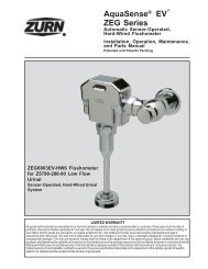
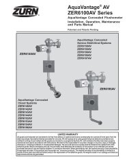
PRESSURE LOSS (PSIG)PRESSURE LOSS (PSIG)Performance Characteristics15105MODEL <strong>950XL</strong> 3/4", 1", 1 1/4", 1 1/2" & 2" (STANDARD & METRIC)FLOW RATES (l/s)1.26 2.52 3.8 5.03.2 6.3 9.5 12.6153/4" (20mm) 1" (25mm) 1 1/4" (32mm) 1 1/2" (40mm)00 20 40 60 802015101.26MODEL <strong>975XL</strong> 1/4", 3/8" & 1/2" (STANDARD & METRIC)PRESSURE LOSS (PSIG)20151010FLOW RATES (GPM)Rated Flow (Established by approval agencies)52" (50mm)15.810300 50 100 150 200 250MODEL <strong>975XL</strong> 3/4", 1", 1 1/4", 1 1/2" & 2" (STANDARD & METRIC)2.523.80.191/4" (6mm)FLOW RATES (l/s)0.38FLOW RATES (l/s)3/4" (20mm) 1" (25mm) 1 1/4" (32mm)5.035550 20 40 60 80 0 50 100 150 200 250FLOW RATES (GPM)0.573/8" (9mm)2015100.761/2" (15mm)3550 3 6 9 12 15FLOW RATES (GPM)Rated Flow (Established by approval agencies)3.2Rated Flow (Established by approval agencies)0.95137103696.3PRESSURE LOSS (kpa)9.51½"(40mm)12.62" (50mm)693515.813710369PRESSURE LOSS (kpa)PRESSURE LOSS (kpa)SPECIFICATIONSMaximum working water pressure 175 PSIMaximum working water temperature 180°FHydrostatic test pressure350 PSIEnd connectionsThreaded NPTANSI B1.20.1Capacity thru Schedule 40 PipePipe size 5 ft/sec 7.5 ft/sec 10 ft/sec 15 ft/sec1/8" 1 1 2 31/4" 2 2 3 53/8" 3 4 6 91/2" 5 7 9 143/4" 8 12 17 251" 13 20 27 401 1/4" 23 35 47 701 1/2" 32 48 63 952" 52 78 105 167Proper performance is dependent upon licensed, qualified personnel performing regular, periodic testing according to ZURNWILKINS’ specifications and prevailing governmental & industry standards and codes and upon following these installation instructions.Failure to do so releases ZURN WILKINS of any liability that it might otherwise have with respect to that device. Suchfailure could also result in an improperly functioning device.®ISSM950(REV. 4/13)ZURN WILKINS1747 Commerce Way, Paso Robles, CA 93446 Phone:855-663-9876 Fax:805-238-5766www.zurn.com4