ETA 08-0818 - bei Powers Europe
ETA 08-0818 - bei Powers Europe
ETA 08-0818 - bei Powers Europe

You also want an ePaper? Increase the reach of your titles
YUMPU automatically turns print PDFs into web optimized ePapers that Google loves.
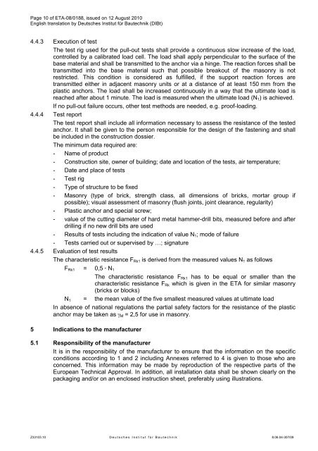
Page 10 of <strong>ETA</strong>-<strong>08</strong>/0188, issued on 12 August 2010English translation by Deutsches Institut für Bautechnik (DIBt)4.4.3 Execution of testThe test rig used for the pull-out tests shall provide a continuous slow increase of the load,controlled by a calibrated load cell. The load shall apply perpendicular to the surface of thebase material and shall be transmitted to the anchor via a hinge. The reaction forces shall betransmitted into the base material such that possible breakout of the masonry is notrestricted. This condition is considered as fulfilled, if the support reaction forces aretransmitted either in adjacent masonry units or at a distance of at least 150 mm from theplastic anchors. The load shall be increased continuously in a way that the ultimate load isreached after about 1 minute. The load is measured when the ultimate load (N 1 ) is achieved.If no pull-out failure occurs, other test methods are needed, e.g. proof-loading.4.4.4 Test reportThe test report shall include all information necessary to assess the resistance of the testedanchor. It shall be given to the person responsible for the design of the fastening and shallbe included in the construction dossier.The minimum data required are:- Name of product- Construction site, owner of building; date and location of the tests, air temperature;- Date and place of tests- Test rig- Type of structure to be fixed- Masonry (type of brick, strength class, all dimensions of bricks, mortar group ifpossible); visual assessment of masonry (flush joints, joint clearance, regularity)- Plastic anchor and special screw;- value of the cutting diameter of hard metal hammer-drill bits, measured before and afterdrilling if no new drill bits are used- Results of tests including the indication of value N 1 ; mode of failure- Tests carried out or supervised by …; signature4.4.5 Evaluation of test resultsThe characteristic resistance F Rk1 is derived from the measured values N 1 as followsF Rk1 = 0,5 · N 1The characteristic resistance F Rk1 has to be equal or smaller than thecharacteristic resistance F Rk which is given in the <strong>ETA</strong> for similar masonry(bricks or blocks)N 1 = the mean value of the five smallest measured values at ultimate loadIn absence of national regulations the partial safety factors for the resistance of the plasticanchor may be taken as γ M = 2,5 for use in masonry.5 Indications to the manufacturer5.1 Responsibility of the manufacturerIt is in the responsibility of the manufacturer to ensure that the information on the specificconditions according to 1 and 2 including Annexes referred to 4 is given to those who areconcerned. This information may be made by reproduction of the respective parts of the<strong>Europe</strong>an Technical Approval. In addition, all installation data shall be shown clearly on thepackaging and/or on an enclosed instruction sheet, preferably using illustrations.Z33103.10 D e u t s c h e s I n s t i t u t f ü r B a u t e c h n i k 8.06.04-307/09