American Institute of Aeronautics and Astronautics 1 ... - Team-Logic
American Institute of Aeronautics and Astronautics 1 ... - Team-Logic
American Institute of Aeronautics and Astronautics 1 ... - Team-Logic
- No tags were found...

You also want an ePaper? Increase the reach of your titles
YUMPU automatically turns print PDFs into web optimized ePapers that Google loves.
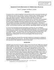
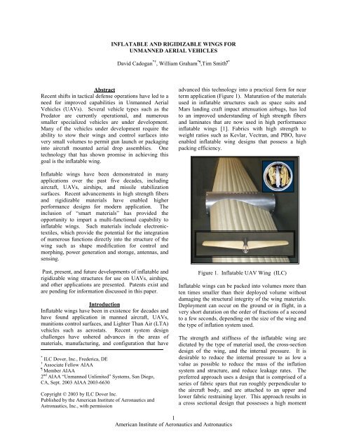
INFLATABLE AND RIGIDIZABLE WINGS FORUNMANNED AERIAL VEHICLESDavid Cadogan *† , William Graham * ,Tim Smith *AbstractRecent shifts in tactical defense operations have led to aneed for improved capabilities in Unmanned AerialVehicles (UAVs). Several vehicle types such as thePredator are currently operational, <strong>and</strong> numeroussmaller specialized vehicles are under development.Many <strong>of</strong> the vehicles under development require theability to stow their wings <strong>and</strong> control surfaces intovery small volumes to permit gun launch or packaginginto aircraft mounted aerial drop assemblies. Onetechnology that has shown promise in achieving thisgoal is the inflatable wing.advanced this technology into a practical form for nearterm application (Figure 1). Maturation <strong>of</strong> the materialsused in inflatable structures such as space suits <strong>and</strong>Mars l<strong>and</strong>ing craft impact attenuation airbags, has ledto an improved underst<strong>and</strong>ing <strong>of</strong> high strength fibers<strong>and</strong> laminates that are now used in high performanceinflatable wings [1]. Fabrics with high strength toweight ratios such as Kevlar, Vectran, <strong>and</strong> PBO, haveenabled inflatable wing designs that possess a highpacking efficiency.Inflatable wings have been demonstrated in manyapplications over the past five decades, includingaircraft, UAVs, airships, <strong>and</strong> missile stabilizationsurfaces. Recent advancements in high strength fibers<strong>and</strong> rigidizable materials have enabled higherperformance designs for modern application. Theinclusion <strong>of</strong> “smart materials” has provided theopportunity to impart a multi-functional capability toinflatable wings. Such materials include electronictextiles,which provide the potential for the integration<strong>of</strong> numerous functions directly into the structure <strong>of</strong> thewing such as shape modification for control <strong>and</strong>morphing, power generation <strong>and</strong> storage, antennas, <strong>and</strong>sensing.Past, present, <strong>and</strong> future developments <strong>of</strong> inflatable <strong>and</strong>rigidizable wing structures for use on UAVs, airships,<strong>and</strong> other applications are presented. Patents exist <strong>and</strong>are pending for information discussed in this paper.IntroductionInflatable wings have been in existence for decades <strong>and</strong>have found application in manned aircraft, UAVs,munitions control surfaces, <strong>and</strong> Lighter Than Air (LTA)vehicles such as aerostats. Recent system designchallenges have ushered advances in the areas <strong>of</strong>materials, manufacturing, <strong>and</strong> configuration that have* ILC Dover, Inc., Frederica, DE† Associate Fellow AIAA Member AIAA2 nd AIAA “Unmanned Unlimited” Systems, San Diego,CA, Sept. 2003 AIAA 2003-6630Copyright © 2003 by ILC Dover Inc.Published by the <strong>American</strong> <strong>Institute</strong> <strong>of</strong> <strong>Aeronautics</strong> <strong>and</strong><strong>Astronautics</strong>, Inc., with permissionFigure 1. Inflatable UAV Wing (ILC)Inflatable wings can be packed into volumes more thanten times smaller than their deployed volume withoutdamaging the structural integrity <strong>of</strong> the wing materials.Deployment can occur on the ground or in flight, in avery short duration on the order <strong>of</strong> fractions <strong>of</strong> a secondto a few seconds, depending on the size <strong>of</strong> the wing <strong>and</strong>the type <strong>of</strong> inflation system used.The strength <strong>and</strong> stiffness <strong>of</strong> the inflatable wing aredictated by the type <strong>of</strong> material used, the cross-sectiondesign <strong>of</strong> the wing, <strong>and</strong> the internal pressure. It isdesirable to reduce the internal pressure to as low avalue as possible to reduce the mass <strong>of</strong> the inflationsystem <strong>and</strong> structure, <strong>and</strong> reduce leakage rates. Thepreferred approach uses a design that is comprised <strong>of</strong> aseries <strong>of</strong> fabric spars that run roughly perpendicular tothe aircraft body, <strong>and</strong> are attached to an upper <strong>and</strong>lower fabric restraining layer. This approach results ina cross sectional design that possesses a high moment1<strong>American</strong> <strong>Institute</strong> <strong>of</strong> <strong>Aeronautics</strong> <strong>and</strong> <strong>Astronautics</strong>
<strong>of</strong> inertia. The surface <strong>of</strong> the resultant inflated structurehas a “bumpy” appearance, as inflatable structuresapproximate the shape <strong>of</strong> a cylinder or sphere uponinflation. A skin can be added to the surface <strong>of</strong> thestructure to provide a smooth aerodynamic surface.Through appropriate design <strong>of</strong> the fabric patterns thatmake up the inflatable wing, a variety <strong>of</strong> wing shapescan be manufactured, including wings that possesscamber.One <strong>of</strong> the more notable features <strong>of</strong> an inflatable wingis its durability. The materials are robust <strong>and</strong> can bepacked <strong>and</strong> deployed numerous times in test or reusewith minimal degradation in performance. The use <strong>of</strong>an inflatable reduces the likelihood <strong>of</strong> damage inshipping, h<strong>and</strong>ling, flight, <strong>and</strong> l<strong>and</strong>ing, through theimpact resiliency <strong>of</strong> the materials, <strong>and</strong> the naturalimpact absorption capabilities <strong>of</strong> an inflatable structure.As a result, there is less <strong>of</strong> a need for highly skilledsupport personnel in the field. A related property <strong>of</strong>inflatable wing design is the ability <strong>of</strong> the wing torecover shape in flight if the load limit is exceeded <strong>and</strong>the wing buckles.Another technology that can be used to create aninflatable wing with a high packing efficiency <strong>and</strong>improved performance is rigidization. Rigidization isthe action by which a flexible inflatable structure isconverted into a rigid composite structure. Once a wingor other surface is “rigidized”, it no longer relies oninflation pressure to maintain its shape. Thistechnology has been most recently applied todeployable space structures such as antennas, solararrays, <strong>and</strong> solar sails [2]. Several mechanisms exist bywhich to rigidize a structure, including thermalchemicalreactions, UV-chemical reactions, <strong>and</strong>inflation gas-chemical reactions.The most notable advantage <strong>of</strong> a rigidizable structure, isthe increased stiffness that results compared to astructure supported by inflation pressure alone.Stiffness increases <strong>of</strong> an order <strong>of</strong> magnitude or morecan be achieved over comparable inflatable onlystructures. This will allow for the evolution <strong>of</strong> thinnerairfoils <strong>and</strong> improved aerodynamic performancecompared to a conventional inflatable wing. A furtheradvantage <strong>of</strong> a rigidizable wing is the elimination <strong>of</strong>inflation gas dependence to maintain the shape <strong>of</strong> thestructure after deployment. Inflation gas is requiredonly to initially deploy the structure.Inflatable aerodynamic surfaces have been consideredfor use in several military UAVs [3,4,5]. These includethe Loitering Electronic Warfare Killer (LEWK)(Figure 2), the US Navy Forward Air Support Munition(FASM), the US Army Quicklook, <strong>and</strong> the SmallUnmanned Aerial Vehicle (SUAV).Figure 2. LEWK Prototype Vehicle (SAIC)BackgroundInflatable wing technology has been used in aircraftapplications since the 1950’s. Many concepts havebeen proposed since the 1930’s [6], <strong>and</strong> numerousincarnations are flying today, some are mentioned inthis paper. Goodyear Aerospace designed <strong>and</strong>manufactured several prototype aircraft using inflatablecomponents during the 1950’s [7]. The GA-33Inflatoplane had capabilities comparable to a J3 Cub(Figure 3).Figure 3. The GA-33 Goodyear Inflatoplane (1956)The airplane was maneuvered into position like awheelbarrow on its own wheel <strong>and</strong> inflated within 5minutes to ~25 psi. It used a two-cycle 40 horsepowerNelson engine that was h<strong>and</strong> started. Its wing span was22 feet <strong>and</strong> had a length <strong>of</strong> 19 feet 7 inches. Theairplane held 20 gallons <strong>of</strong> fuel <strong>and</strong> carried a maximumweight <strong>of</strong> 240 lbs. Its range was 390 miles with anendurance <strong>of</strong> 6.5 hours. Its cruise speed was 60 mph.The inflatoplane could be dropped by container behindenemy lines as a means <strong>of</strong> rescuing downed pilots Itwas ideally suited for both l<strong>and</strong> <strong>and</strong> water use. A total<strong>of</strong> twelve Inflatoplanes were built. Development,testing, <strong>and</strong> evaluation <strong>of</strong> the inflatable airplanecontinued through 1972 <strong>and</strong> the project was finallyterminated in 1973.2<strong>American</strong> <strong>Institute</strong> <strong>of</strong> <strong>Aeronautics</strong> <strong>and</strong> <strong>Astronautics</strong>
The 2 place GA-466 Inflatoplane was also designed bythe Goodyear Company in the 1950s (Figure 4). Theairplane was inflated to ~25 psi in about 6 minutes.This aircraft used a 60 horsepower McCulloch 4318engine that was h<strong>and</strong> started. Its wing span was 28 feet<strong>and</strong> had a length <strong>of</strong> 19 feet 2 inches. The airplane held18 gallons <strong>of</strong> fuel <strong>and</strong> had a gross weight <strong>of</strong> 740pounds. The range <strong>of</strong> this airplane was 275 miles withan endurance <strong>of</strong> 5.4 hours. Its cruise speed was 55mph, stall speed was 43 mph, <strong>and</strong> had a maximumspeed <strong>of</strong> 70 mph.the NACA 0018 geometry. Aerostats are tethered to theground during operation <strong>and</strong> are used to carry anairborne radar platform for border surveillance. Theycan fly in winds <strong>of</strong> 60 kts, with gusts up to 90 kts. Thefins are constructed from a multi-ply fabric thatprovides gas retention <strong>and</strong> a structural layer to reactaerodynamic loading. The envelopes are constructedfrom a flexible composite material using thermal <strong>and</strong>radio frequency sealing techniques.Figure 6. 420,000ft 3 aerostatFigure 4. The GA-466 Goodyear InflatoplaneILC Dover employed inflatable wing technology in the1970s with the invention <strong>of</strong> the Apteron unmannedaerial vehicle (Figure 5). This small vehicle was able tobe stored in a small volume for ease in portability, <strong>and</strong>launched from any remote location. This aircraft had a5.1 ft wingspan, <strong>and</strong> a 0.5 hp engine. The entire craftweighed 7 lbs. Elevons were used for flight control.Inflatable fins <strong>of</strong> similar design have been tested indeployable munitions stabilization applications. Onesuch program was the Weapons Integration <strong>and</strong> DesignTechnology program (WIDT) for the Air ForceResearch Laboratory, Eglin AFB, Florida (Figure 7). Inthis program, various technologies including inflatablefins were developed for creating a compact vehiclepackage with a reduced radar signature for externalweapons carriage. The inflatable stabilization finprototypes were designed for use with 250 lb <strong>and</strong> 500 lbbombs, deployed at altitudes <strong>of</strong> 300 to 25,000 ft <strong>and</strong> atspeeds up to Mach 1.2. Inflation occurred in under 150milli-seconds using a CO 2 gas generator. The inflationpressure was 200 psi.Figure 5. The ILC Dover ApteronInflatable wing/fin technology has also beendemonstrated for several decades on lighter than air(LTA) vehicles that use tail-fin assemblies for stability<strong>and</strong> control (Figure 6). These vehicles range in sizefrom 15 ft long advertising vehicles to 595,000 ft 3aerostats [8]. The fins are symmetrical airfoils based onFigure 7. WIDT Munitions FinInflatable Wing DevelopmentInflatable wings constructed by ILC are typicallycomprised <strong>of</strong> a gas retaining bladder <strong>and</strong> a structuralrestraint that reacts inflation <strong>and</strong> aerodynamic loads3<strong>American</strong> <strong>Institute</strong> <strong>of</strong> <strong>Aeronautics</strong> <strong>and</strong> <strong>Astronautics</strong>
(Figure 8). Several methodologies have been used inthe past, including inflated tubes <strong>of</strong> various diameterscovered by a tensioned skin <strong>and</strong> sometimes supportedunderneath by a foam [9, 10, 11]. However, this paperfocuses on a highly efficient multi-spar approach,which provides several advantages over tubularapproaches.<strong>and</strong> if filled with a compressible spacer material, wouldhave little impact on the packing volume <strong>of</strong> the wing.Minimizing spacer material also limits the potential foradverse shape effects due to compression set <strong>of</strong> thismaterial during packing <strong>and</strong> storage.Figure 8. Inflatable Wing RestraintIn the multi-spar approach, wing stiffness is dictated byinternal pressure <strong>and</strong> the modulus <strong>of</strong> elasticity <strong>of</strong> therestraint material, <strong>and</strong> can be elevated through the use<strong>of</strong> higher strength <strong>and</strong> modulus materials that canwithst<strong>and</strong> higher internal pressures. The cross-section<strong>of</strong> this type <strong>of</strong> airfoil reveals that the geometry <strong>of</strong> thewing is defined by a series <strong>of</strong> intersecting cylinders(Figure 9).NACA 8318 with even spar distributionNACA 0018 Symmetrical with even spar distributionNACA 4318 with distributed spars & skinFigure 9. Inflatable Wing Cross-SectionsThe exterior <strong>of</strong> the wing has a “bumpy” appearance, butcan be covered with a skin to improve aerodynamics(Figure 10). The volume difference between theinflated shape <strong>and</strong> the ideal airfoil shape is minimal,Figure 10. Inflatable Wing with Skin in Wind TunnelInflatable wings can be made tapered, swept, or alteredin planform through appropriate patterning <strong>of</strong> therestraint. Similarly, with careful patterning, the airfoilcan be made to have camber. Fiber positioning is usedin the design <strong>of</strong> the external restraint <strong>and</strong> internal sparsto control elongation <strong>and</strong> therefore dimensionalaccuracy <strong>of</strong> the construction. The use <strong>of</strong> internal sparsto separate the upper <strong>and</strong> lower external restraintsyields a wing that optimizes the cross-sectional moment<strong>of</strong> inertia <strong>of</strong> the wing by maximizing internalpressurized area. This yields the lowest possibleinternal pressure required for the wing which in-turnyields lower potential for leakage, lower inflationsystem mass, <strong>and</strong> a lower packed volume.Inflatable Wing Materials - The restraints aremanufactured from high modulus fibers such as Kevlar,Vectran, or PBO. The fibers are selected based on thestorage <strong>and</strong> performance requirements <strong>of</strong> the vehicle(Tables 1 & 2). Packing characteristics also play alarge part in the selection <strong>of</strong> fibers. Some fibers, suchas PBO, are sensitive to compression failureexperienced in bending, which significantly degradesstrength <strong>and</strong> stiffness, <strong>and</strong> are less desirable. PBO alsodegrades when exposed to various wavelengths <strong>of</strong> light,reducing its tenacity. However, even with these factors,PBO still retains a large percentage <strong>of</strong> its strength <strong>and</strong>stiffness to make it competitive for various applications.Vectran has been used by ILC in numerous aerospaceapplications including the Mars Pathfinder <strong>and</strong> MERimpact attenuation airbags [1]. Notable properties <strong>of</strong>this fiber include excellent resistance to degradationfrom h<strong>and</strong>ling <strong>and</strong> packing, as well as an increase instrength in cold environments. Kevlar is another highstrength fiber that is slightly lower in cost <strong>and</strong> available4<strong>American</strong> <strong>Institute</strong> <strong>of</strong> <strong>Aeronautics</strong> <strong>and</strong> <strong>Astronautics</strong>
in a wide range <strong>of</strong> weaves. To date, inflatable wingshave been manufactured from Vectran <strong>and</strong> Kevlar.MaterialSPECTRA/DYNEEMASpecificGravityCostYarnTenacityTensileStrengthTensileModulusStraintoFailureg/cm^3 $/lb g/den x 10^3 psi x 10^6 psi %- Dyneema 0.97 23 40 507 16 3.5- 900 UHMW PE 0.97 23 375 17 3.5- 1000 UHMW PE 0.97 29 32 435 25 2.7VECTRANPBO- HS 1.41 22-90 23 412 9.4 3.3- M 1.4 15 9 161 7.6 2- AS 1.54 110 42 840 26 3.5- HM 1.56 110 42 840 39 2.5KEVLAR- 49 Aramid Fiber 1.46 25 23 420 9.8 2.5- 29 Aramid Fiber 1.46 15-40 23 420 12 3.6- 68 Aramid Fiber 1.46 15-40 420 25–26- 149 Aramid Fiber 1.55 25 18 340 21 1.45TECHNORA- T-240 1.45 15-30 28 414 15.8 4.4FIBERGLASS- S-Glass 2.49 5.5 21 665 13.5 5.7- E-Glass 2.6 0.85 15.1 500 12.4 4.8GRAPHITE/CARBON- H.S. Pan 1.7–1.8 20 21.3 410–580 33–36 2-2.5- UHS Pan 1.7–1.8 20 31.3 590–830 38-42 1.8- HM Pan/Pitch 1.8–2.0 20 14.2 250–500 50–80 0.4- UHM Pitch 2.0–2.2 20 11.9 300–360 90–130 0.3Packaging & Deployment - Several folding techniquescan be used to package the inflatable wings fordeployment. R<strong>and</strong>om, z-folding, rolling, <strong>and</strong>combinations are usually considered. Deployment rate<strong>and</strong> effects on flight dynamics are leading criteria in theselection <strong>of</strong> the method. Inflatable wings can pack intovolumes more than ten times smaller than theirdeployed volume. A well packed structure can exceedpacking efficiencies (package volume to materialvolume) <strong>of</strong> 60%.Deployment synchronicity is improved as the rates <strong>of</strong>deployment are increased. Some control can also beachieved through specific packing patterns <strong>and</strong> control<strong>of</strong> the inflation path. This approach can also be used tobuild stiffness <strong>of</strong> the wing from the root duringdeployment, to eliminate the potential for wing foldback.Regardless <strong>of</strong> the path they take duringdeployment, inflatable wings always achieve their finalshape because <strong>of</strong> their robust nature. An example <strong>of</strong> awing with a 10:1 deployed to packed volume can beseen in Figure 11.Table 1. High Performance Fiber Physical PropertiesNumerous materials are available <strong>and</strong> suitable for thedesign <strong>and</strong> construction <strong>of</strong> the internal bladder.Material selection is typically driven by flex cracking<strong>and</strong> modulus at cold temperature, manufacturingprocess, resistance to gas permeation, <strong>and</strong> resistance todeveloping pinholes when folded or flexed.Polyurethane is <strong>of</strong>ten used, but specializedpolyurethane compounds <strong>and</strong> laminates, such asArmorflex, are also applicable. The materials used inthe construction <strong>of</strong> the inflatable wings have lowdielectric constant <strong>and</strong> are therefore low observablefrom a radar perspective.PROPERTYPOLYESTERTenacity (g/d) 8.3Modulus (g/d) 80Shrinkage @ 350°F, % 1.6Resistance to FlexCrackingUV DegradationHydrolytic StabilityOxidation ResistanceCoating AdhesionCreep Under LoadAbrasion ResistanceExcellentGoodGoodGoodExcellentGoodFairElongation @ Break 16.3Density 1.38KEVLAR SPECTRA VECTRAN22 30 23458 1400 525Minimal Decomposes @ 296°F MinimalPoor Excellent GoodPoor Good PoorExcellent Excellent ExcellentExcellent Excellent ExcellentGood Poor ExcellentExcellent Poor ExcellentPoor Excellent Good3.6 3.5 3.31.44 0.97 1.4Table 2. Fiber CharacteristicsFigure 11. Packed Inflatable WingSystem Analysis - There are several benefits <strong>and</strong>drawbacks to the use <strong>of</strong> inflatable wings that must beconsidered by the user prior to selection <strong>of</strong> atechnology. The greatest advantage that inflatablesprovide over conventional structures is in packaging.This is usually at the core <strong>of</strong> a decision to considerinflatable structures for wings. Some higher orderbenefits <strong>and</strong> drawbacks <strong>of</strong> inflatable vs conventionallyconstructed (metal or composite) wings include thefollowing:Benefits:- High packing efficiency (low packed volume)- High G deployable- Robust / simple / reliable (no moving parts)5<strong>American</strong> <strong>Institute</strong> <strong>of</strong> <strong>Aeronautics</strong> <strong>and</strong> <strong>Astronautics</strong>
- Low cost- Long storage life- Recoverable / durable / reusable- Can be morphed or shape modified for control- Can recover shape if buckling occurs in flight (gustload)- Inflatable structures dampen vibrations wellDrawbacks:- Potential for leakage / ballistic penetration- Thicker airfoil required for high stiffness – lessefficient aerodynamically- Aspect ratio limited for high wing loading- Inflation system mass burden- Need for make-up gas (thermal/altitude excursions)This list is not inclusive but is representative <strong>of</strong> theaspects <strong>of</strong> the technology for consideration.Many <strong>of</strong> these drawbacks can be addressed by applyinga materials technology known as “rigidization”. In thisapproach, a flexible material is packed <strong>and</strong> deployed asin the case <strong>of</strong> the inflatable wing, but then undergoes achange in properties <strong>and</strong> becomes rigid, no longerrequiring the support <strong>of</strong> inflation gas to maintain itsgeometry. This approach will be discussed in the nextsection.Inflation Systems - Inflation systems can be configuredfrom several well understood technologies such asbottled compressed gas, chemical gas generators, feedlines from engine compressors, etc. DC electricblowers are used in aerostats <strong>and</strong> are very efficientsources <strong>of</strong> inflation gas in these low pressure systems.Inflation system selection will depend on severalcriteria focused on mission requirements such asdeployment time, thermal <strong>and</strong> altitude gradients afterdeployment, <strong>and</strong> the need for a pressurizationmaintenance source for long duration missions.Integrated Technologies – There are a number <strong>of</strong>technologies that are maturing rapidly that can exp<strong>and</strong>the inflatable wing’s performance, several <strong>of</strong> which arebeing studied for application. The collapsible <strong>and</strong>deformable nature <strong>of</strong> a textile assembly makes aninflatable wing an attractive platform upon which toapply wing morphing techniques. Actuators can beapplied strategically to alter the shape, size <strong>and</strong> crosssection <strong>of</strong> the inflatable wing for various flight regimes.This approach has the potential to be extremely masseffective in comparison to mechanical technologies,especially if electronic textiles can be applied.Electronic textiles, or E-textiles, are an emerging class<strong>of</strong> materials that combine electrical components directlyinto textile materials, such as the restraint in this case[12]. These materials can be made to perform variousfunctions such as changing shape via constriction,producing power, acting as sensors or embeddedantennas, or as microcircuits.E-textiles are being developed for use in inflatable wingstructures as control mechanisms. Throughdeformation <strong>of</strong> the wing geometry, a simple method <strong>of</strong>control can be obtained that reduces part count <strong>and</strong>complexity <strong>of</strong> wing systems. Control <strong>of</strong> this nature alsoprovides a smooth transition at the trailing edge <strong>of</strong> thewing, thus reducing aerodynamic disturbances <strong>of</strong>mechanical systems. This is accomplished throughconstriction or deformation <strong>of</strong> various componentswithin the inflatable wing structure, especially the aftthird <strong>of</strong> the airfoil, where loading <strong>and</strong> cross-sectionalstiffness are lower <strong>and</strong> can be more easily maneuvered.Examples <strong>of</strong> how Nastic cells, a biomemetic style <strong>of</strong>actuation system noted in plants, are shown in Figure12. Through inflation <strong>of</strong> these small tubes,foreshortening the selected area can locally alter theshape <strong>of</strong> the wing. Deformation <strong>of</strong> this nature isdesirable for long duration camber change, but may betoo low in frequency response to be used as a controlmechanism.Inflated ActuatorsUn-Inflated ActuatorsFigure 12. Nastic Cells for Morphing Inflatable WingsThe most promising method <strong>of</strong> morphing wing shapesfor control purposes focuses on the use <strong>of</strong> piezoelectricmaterials. Several approaches <strong>of</strong> application <strong>of</strong> thesematerials to inflatable wings are currently underdevelopment. Two different types, Thunder <strong>and</strong>Macro-Fiber Composite (MFC) actuators produced byFACE International <strong>and</strong> Smart Material Inc.respectively, are being applied to the surface <strong>of</strong> wingsfor test. These can be applied in a localized or a globalformat. Figure 13 shows one method <strong>of</strong> altering theshape <strong>of</strong> the wing that is currently in test. Flattening <strong>of</strong>the bumps in the inflatable wing extends the surface runlength <strong>and</strong> thus deforms the shape <strong>of</strong> the wing.6<strong>American</strong> <strong>Institute</strong> <strong>of</strong> <strong>Aeronautics</strong> <strong>and</strong> <strong>Astronautics</strong>
Excitation can occur rapidly thus allowing thetechnique to be used for control applications via localmorphing.Un-deflected ActuatorsDeflected ActuatorsFigure 13. Piezoelectric Actuators for MorphingInflatable WingsRigidizable Wing DevelopmentA number <strong>of</strong> potential drawbacks have been identified<strong>and</strong> discussed with regard to inflatable wings. ILC hasdeveloped a technique for addressing these issues <strong>and</strong>creating an inflatable wing that can be packaged into asmall volume, yet provide the same structural properties<strong>of</strong> a conventional composite or metal ring. This method<strong>of</strong> transformation is known as “rigidization” <strong>and</strong> iscurrently being patented for this application.Rigidization is a process by which a flexible material isaltered physically by an external controlling influence<strong>and</strong> becomes a solid composite structure [13, 14, 15,16]. Numerous mechanisms are available, but the mostpromising appear to be Ultra-Violet (UV), <strong>and</strong> InflationGas Reaction rigidization. UV Rigidization uses UVradiation to cause a chemical reaction (cure) in a matrixresin, <strong>and</strong> Inflation Gas Reaction resin uses an inflationgas that is loaded with a curative agent that reacts witha benign matrix resin in the structure. Once the wing ismade rigid, within seconds to minutes depending onresin chemistry, the wing no longer requires inflation toprovide structural stability.The most practical in the near term for wing structuresappears to be UV-chemical exposure. In this case, areinforcement fabric is coated with an uncured polymerthat chemically hardens when exposed to Ultra-Violetlight to form a composite structure. The UV source canbe the sun or from internal sources such as LEDs.Timing <strong>of</strong> the rigidization event is controlled by theresin chemistry, <strong>and</strong> can be on the order <strong>of</strong> tens <strong>of</strong>seconds if required. The wavelength at which thematerial rigidizes can be shifted to accommodatemanufacturing <strong>and</strong> field use needs if required, or to cureat various rates under specified conditions. Resin cureis accelerated under elevated thermal conditions <strong>and</strong>may require an integrated method <strong>of</strong> heating the wingsduring cure if very cold environments are encountered.The reinforcement fabric can be one <strong>of</strong> severalmaterials normally used in composite structures, butglass or quartz is normally preferred for ease <strong>of</strong> UVtransmission. Distributed reinforcements <strong>of</strong> higherperformance fibers such as carbon can be used ifrequired to further optimize structural efficiency. Forbrevity the UV system only will be discussed.The motivation for this work is to provide an inflatablewing with properties that approach that <strong>of</strong> a fixed rigidwing made from metal or composite materials. Amajority <strong>of</strong> the benefits <strong>of</strong> inflatable wings still exist,however, some <strong>of</strong> the drawbacks can now be addressed.This provides some advantages in several areasincluding the following:• Reduced puncture/leakage vulnerability• Stiffer than an inflatable wing (higher load factor)• Thinner, Higher Aspect Ratio Wing = Less Drag,improved aerodynamics• No gas leakage / make-up gas mass or complexity• Longer flight duration via efficient wing design• Smaller, Lighter Deployment System• Minimal inflation pressure required (3-5 psid)The are many benefits <strong>of</strong> this approach that lead to thepotential for some high performance UAV systems.However, there is still one limitation to this approach,which must be considered. The time duration <strong>of</strong> thecure <strong>of</strong> the composite <strong>and</strong> the design <strong>of</strong> the thin,potentially high aspect ratio inflatable wings, requirethat the wings not be “loaded” during rigidization. Inother words, the UAV will probably have to bedeployed <strong>and</strong> rigidized while suspended from aparachute. The parachute <strong>and</strong> possibly the inflationsystem can then be jettisoned prior to the flightcomponent <strong>of</strong> the mission. If the wings were to beaerodynamically loaded, they would have to rely on thedesign <strong>of</strong> the inflatable structure <strong>and</strong> thus have a thickercross-section <strong>and</strong> be inflated with a high-pressureinflation source.Inflatable rigidizable wing components are currentlybeing designed <strong>and</strong> fabricated in a university spacegrant consortium flight experiment program. In thiseffort the University <strong>of</strong> Kentucky is structuring a highaltitude balloon drop test for a UAV with inflatablerigidizable wings supplied by ILC. The wings will be7<strong>American</strong> <strong>Institute</strong> <strong>of</strong> <strong>Aeronautics</strong> <strong>and</strong> <strong>Astronautics</strong>
inflated <strong>and</strong> rigidized during ascent (from 60,000 to80,000 ft), <strong>and</strong> then the aircraft will be dropped from analtitude <strong>of</strong> approximately 80,000 ft. Photography <strong>and</strong>location transponders will be used to monitor thedeployment <strong>and</strong> flight characteristics <strong>of</strong> the wings. Inthis case the sun’s radiant energy will be used torigidize the wings.Several subsections <strong>of</strong> the wing were fabricated <strong>and</strong>tested to verify manufacturing techniques <strong>and</strong> structuralproperties <strong>of</strong> the rigidized component. The completedwing shown in Figure 14 is the test model <strong>of</strong> theinflatable rigidizable wing, manufactured from afiberglass/UV epoxy laminate.The technology is also scalable to accommodate theneeds <strong>of</strong> high altitude airships, munitions systems, <strong>and</strong>similar applications.AcknowledgmentThis work was possible through contributions byseveral people <strong>and</strong> organizations by way <strong>of</strong> fundingsupport, technology support, <strong>and</strong> materialsdevelopment. The authors wish to thank SAIC, TheUniversity <strong>of</strong> Kentucky Aerospace EngineeringDepartment, Mevicon, Adherent Technologies, NASALaRC Structures & Dynamics Branch, Office <strong>of</strong> NavalResearch <strong>and</strong> NASA DFRC for their support <strong>and</strong>involvement in this work.References[1] Cadogan D., S<strong>and</strong>y C., Grahne M., Development<strong>and</strong> Evaluation <strong>of</strong> the Mars Pathfinder Inflatable AirbagL<strong>and</strong>ing System, 49 th International AstronauticalCongress, 1998.[2] Cadogan D., Grahne M., Mikulas M., InflatableSpace Structures: A New Paradigm for Space StructureDesign, 49 th International Astronautical Congress,1998.[3] Palmer, M., LEWK Joins SAIC’s Growing Flock,SAIC Spectrum Newsletter, Fall 2001.Figure 14. UV Rigidized WingThe test unit was evaluated for structural stiffness <strong>and</strong>manufacturing process accuracy. Information derivedfrom the sub-component tests was used in thedevelopment <strong>of</strong> the rigidizable wing section. This is aprototype <strong>of</strong> the wing that was successfully flown in theBIG BLUE balloon flight experiment in May <strong>of</strong> 2003[17]. The wing is a 16 spar symmetrical airfoil basedon a based on an E398 airfoil with a chord <strong>of</strong> 12 in, <strong>and</strong>a half span <strong>of</strong> 36 in. The airfoil is designed to support a10.4 lb vehicle with a 2G wing-loading, <strong>and</strong> has a factor<strong>of</strong> safety <strong>of</strong> > 2.0 over ultimate.Summary <strong>and</strong> ConclusionsSignificant advancements have been made withrespect to deployable inflatable wings over the past fewyears, which have made them both attractive <strong>and</strong> viablefor UAV application <strong>and</strong> design integration. Advancesin rigidization technologies that yield high stiffnessdeployable wings, multi-functional structures, <strong>and</strong>morphing technologies, have exp<strong>and</strong>ed the utility <strong>of</strong> thetechnology. Applicability <strong>of</strong> these technologies tovarious classes <strong>of</strong> UAVs is evident (compact carriage<strong>and</strong> gun launch, as well as extra-planetary research).[4] Palmer, M., Forward Air Support Marine (FASM)Briefing, Reconnaissance & Surveillance Operation(RSO) Website (http://rso.saictuc.com/).[5] Small UAV Program Website, NAVAIR, 2003,(http://uav.navair.navy.mil/smuav/).[6] McDaniel, United States Patent Office, PatentNumber 1,905,298, 1933.[7] Jerry Jay's Wing <strong>and</strong> a Prayer Page -http://www.geocities.com/Athens/Ithaca/1397/.[8] ILC Dover Inc. Aerostat Development -http://www.ilcdover.com/Aerostats/aero.htm.[9] Priddy, United States Patent Office, Patent Number1,905,298, 1933.[10] Sebrell, United States Patent Office, PatentNumber 1,905,298, 1933.[11] Haggard, United States Patent Office, PatentNumber 1,905,298, 1933.8<strong>American</strong> <strong>Institute</strong> <strong>of</strong> <strong>Aeronautics</strong> <strong>and</strong> <strong>Astronautics</strong>
[12] Cadogan, D.P., Shook, L. S., Manufacturing <strong>and</strong>Performance Assessments <strong>of</strong> Several Applications <strong>of</strong>Electrotextiles <strong>and</strong> Large Area Circuits, MaterialsResearch Society, Boston MA, 2002.[13] Cohee, D. et. Al., Method <strong>of</strong> Making ThreeDimensional Articles From Rigidizable PlasticComposites. United States Patent Office, PatentNumber 5,651,848, 1997.[14] Allred, R., Scarborough, S., Cadogan, D, McElroy,P., UV Rigidizable Isogrid Structures, 43rdAIAA/ASME/ASCE/AHS/ASC SDM Conference,Denver, CO, 2002.[15] Lin, J.K., Sapna, G.H., Cadogan, D.P.,Scarborough, S.E., “Inflatable Rigidizable IsogridBoom Development,” AIAA-2002-1297, 43rdAIAA/ASME/ ASCE/AHS/ASC Structures, StructuralDynamics, <strong>and</strong> Materials Conference <strong>and</strong> ExhibitAIAA Gossamer Spacecraft Forum, Denver, CO: April22-25, 2002.[16] Cadogan, D.P,. <strong>and</strong> Scarborough S. E..“Rigidizable Materials for Use in Gossamer SpaceInflatable Structures,” AIAA-2001-1417, 42 ndAIAA/ASME/ ASCE/AHS/ASC Structures, StructuralDynamics, <strong>and</strong> Materials Conference <strong>and</strong> ExhibitAIAA Gossamer Spacecraft Forum, Seattle, WA: April16-19, 2001.[17] University <strong>of</strong> Kentucky Collge <strong>of</strong> EngineeringB.I.G. B.L.U.E. project -http://www.engr.uky.edu/bigblue/home.htm.9<strong>American</strong> <strong>Institute</strong> <strong>of</strong> <strong>Aeronautics</strong> <strong>and</strong> <strong>Astronautics</strong>