Instruction Manual - Sierra Instruments
Instruction Manual - Sierra Instruments
Instruction Manual - Sierra Instruments

You also want an ePaper? Increase the reach of your titles
YUMPU automatically turns print PDFs into web optimized ePapers that Google loves.
<strong>Sierra</strong> <strong>Instruments</strong> <strong>Instruction</strong> <strong>Manual</strong>SmartTrak ® 100 SeriesSmartTrak ® 100 SeriesMass Flow Meters and ControllersModels: C100, M100, 100 HP, C101, M101, C140<strong>Instruction</strong> <strong>Manual</strong>IM-100, Revision: FFebruary 20131
<strong>Sierra</strong> <strong>Instruments</strong> <strong>Instruction</strong> <strong>Manual</strong>SmartTrak ® 100 SeriesGLOBAL SUPPORT LOCATIONS: WE ARE HERE TO HELP!CORPORATE HEADQUARTERS5 Harris Court, Building L Monterey, CA 93940Phone (831) 373-0200 (800) 866-0200 Fax (831) 373-4402www.sierrainstruments.comEUROPE HEADQUARTERSBijlmansweid 2 1934RE Egmond aan den HoefThe NetherlandsPhone +31 72 5071400 Fax +31 72 5071401ASIA HEADQUARTERSSecond Floor Building 5, Senpu Industrial park25 Hangdu Road Hangtou TownPu Dong New DistrictShanghai, P.R. China Post Code 201316Phone: + 8621 5879 8521 Fax: +8621 5879 8586IMPORTANT CUSTOMER NOTICE: OXYGEN SERVICE<strong>Sierra</strong> <strong>Instruments</strong>, Inc. is not liable for any damage or personal injury, whatsoever, resulting from the use of<strong>Sierra</strong> <strong>Instruments</strong> standard mass flow meters or controllers for oxygen gas. You are responsible fordetermining if this mass flow meter or controller is appropriate for your oxygen application. You areresponsible for cleaning the mass flow meter or controller to the degree required for your oxygen flowapplication.© COPYRIGHT SIERRA INSTRUMENTS 2012No part of this publication may be copied or distributed, transmitted, transcribed, stored in a retrieval system,or translated into any human or computer language, in any form or by any means, electronic, mechanical,manual, or otherwise, or disclosed to third parties without the express written permission of <strong>Sierra</strong> <strong>Instruments</strong>.The information contained in this manual is subject to change without notice.TRADEMARKSSmartTrak ® 100 Series and Dial-A-Gas ® is a Registered Trademark of <strong>Sierra</strong> <strong>Instruments</strong>, Inc. Other productand company names listed in this manual are trademarks or trade names of their respective manufacturers.SMART-TRAK® 2 NAME CHANGEPlease note that the family name of the Smart-Trak Series has been renamed from Smart-Trak ® 2 toSmartTrak ® 100 Series. It is the same great product, but with a new look (label).2
<strong>Sierra</strong> <strong>Instruments</strong> <strong>Instruction</strong> <strong>Manual</strong>SmartTrak ® 100 SeriesTable of ContentsChapter 1: Introduction .................................................................................................... 5Welcome to the future of gas flow measurement! ................................................................. 5Using This <strong>Manual</strong> ................................................................................................................. 5Safety Information ................................................................................................................. 6Receipt of your instrument..................................................................................................... 7The SmartTrak Flow Sensing Principle ................................................................................. 9Chapter 2: Installation ..................................................................................................... 11Before You Begin Installation ............................................................................................. 11Pre-Installation Check List .................................................................................................. 12Installing the Instrument—Plumbing ................................................................................... 13Compression Fittings ........................................................................................................... 13VCO Fittings ........................................................................................................................ 13VCR Fittings ........................................................................................................................ 141/4 Inch Female NPT ........................................................................................................... 14Installing your Instrument—Mechanical Mounting ............................................................ 15Installing your Instrument—Electrical Connections ........................................................... 16Figure 2-3: HD DB-15 Connector Pin Configuration (on the instrument) .......................... 18Figure 2-4: Wiring Definitions for Optional Communication Cable ................................... 18Figure 2-5: Power Supply Requirements ............................................................................. 19Chapter 3: Analog Operation ........................................................................................ 22Analog Operation, Mass Flow Controller ............................................................................ 23SmartTrak Features .............................................................................................................. 24Setpoint Adjustment............................................................................................................. 24Changing the Output or Setpoint Signals............................................................................. 24Over-Range Condition ......................................................................................................... 24<strong>Manual</strong> Valve Override—Valve Close ................................................................................ 25<strong>Manual</strong> Valve Override—Valve Purge Function ................................................................ 25Important Notes About Purging ........................................................................................... 25Purging Non-Reactive Gases: .............................................................................................. 25Purging Reactive Gases: ...................................................................................................... 25Chapter 4: Digital Operation with Pilot Module .......................................................... 27Introduction to Pilot Module Features and Capabilities ...................................................... 27Pilot Module Operation, Mass Flow Meters ........................................................................ 29Pilot Module Operation, Mass Flow Controllers: ................................................................ 30Making Changes Using the Lower Level Screens: ..................................................................... 38Lost Passwords and General Customer Service: ....................................................................... 473
<strong>Sierra</strong> <strong>Instruments</strong> <strong>Instruction</strong> <strong>Manual</strong>SmartTrak ® 100 SeriesChapter 5: Digital Operation RS-232 & SmartTrak Software ................................... 48Power Up Your Instrument ................................................................................................. 48Power Up Your Computer .................................................................................................. 50Loading the SmartTrak Software ........................................................................................ 50Connecting SmartTrak to Your Computer .......................................................................... 51If your computer has a serial port… .................................................................................... 51If your computer has no serial port, but has a USB port….................................................. 53If you plan to control more than one SmartTrak instrument from your computer… .......... 53Running The SmartTrak Software ....................................................................................... 55Chapter 6: Technical Support & Service ...................................................................... 68Factory Calibration—All Models ........................................................................................ 70<strong>Instruction</strong>s for Returning Your Instrument for Service ...................................................... 70Appendix A: C100/M100 SmartTrak ® Product Specifications, Dimensions andMountingAppendix B: C101/M101 MicroTrak Product SpecificationsAppendix C: C140M Ultra-Low ΔP Product Specifications, Dimensions andMountingAppendix D: Addendum to the SmartTrak <strong>Instruction</strong> <strong>Manual</strong>Appendix E: Gas Tables & K-Factors (same for all 100 Series)Appendix F: Flow Chart for Pilot Module User Interface (same for all 100 Series)Appendix G: PIN Configuration (same for all 100 Series)Appendix H: SmartTrak Basic Commands (same for all 100 Series)4
<strong>Sierra</strong> <strong>Instruments</strong> <strong>Instruction</strong> <strong>Manual</strong>SmartTrak ® 100 SeriesCHAPTER 1: INTRODUCTIONWelcome to the future of gas flow measurement!This manual is your guide to SmartTrak. Visit the <strong>Sierra</strong> <strong>Instruments</strong> websitewww.sierrainstruments.com any time for more information about this product.The SmartTrak instruments offer a variety of features for ease of operation. Amongthese features: Dial-A-Gas®: allows a user to change from among 10 gases while maintainingaccuracy. The Optional Pilot Module: control electronics that offers both display andcontrol options at the user’s fingertips. Digital Electronics: maximum performance with minimum noise plusexceptional tuning capability. Choice of Analog Communications Options and RS-232 with everySmartTrak instrument. Flexible Design with many functions that can be re-configured on-site by theuser. Compact Footprint that allows SmartTrak to fit almost anywhere. Wide range of sizes for gas flow from 0.1 sccm to 1400 slpm. And many moreUsing This <strong>Manual</strong>This manual is organized into six chapters: Chapter 1: Introduction and Theory of Operation. Chapter 2: Installation, Plumbing & Wiring instructions. Chapter 3: Analog Operation. Chapter 4: Digital Operation with the Optional Pilot Module. Chapter 5: Digital Operation with RS-232 & SmartTrak Software. Chapter 6: Technical Support and Service.5
<strong>Sierra</strong> <strong>Instruments</strong> <strong>Instruction</strong> <strong>Manual</strong>SmartTrak ® 100 SeriesThere are also 7 Appendices: Appendix A: C100/M100 SmartTrak® Product Specifications, Dimensionsand Mounting Appendix B: C101/M 101 MicroTrak Product Specifications Appendix C: C140M Ultra-Low ΔP Product Specifications, Dimensionsand Mounting Appendix D: Addendum to the SmartTrak <strong>Instruction</strong> <strong>Manual</strong> Appendix E: Gas Tables & K-Factors (same for all 100 Series) Appendix F: Flow Chart for Pilot Module User Interface (same for all 100Series) Appendix G: PIN Configuration (same for all 100 Series) Appendix H: SmartTrak Basic Commands (same for all 100 Series)Throughout this manual, we use the word instrument as a generic term torepresent all models of <strong>Sierra</strong> <strong>Instruments</strong>’ SmartTrak Series 100 mass flowmeters and controllers.SAFETY INFORMATIONCaution and warning statements are used throughout this book to draw yourattention to important information.Warning!This statement appears with information thatis important to protect people and equipmentfrom damage. Pay very close attention to allwarnings that apply to your application.Caution!This statement appears with information that isimportant for protecting your equipment andperformance. Read and follow all cautions thatapply to your application.6
<strong>Sierra</strong> <strong>Instruments</strong> <strong>Instruction</strong> <strong>Manual</strong>SmartTrak ® 100 SeriesRECEIPT OF YOUR INSTRUMENTWhen receiving the instrument, carefully check the outside packing carton fordamage that may have incurred during shipment. If the carton is damaged, notifythe local carrier and submit a report to the factory or distributor. Remove thepacking slip and check that all ordered components are present and match yourspecifications (as ordered). Make sure any spare parts or accessories are notdiscarded with the packing material. Do not return any equipment to the factorywithout first contacting one of <strong>Sierra</strong>’s Technical Support Centers:USA (Headquarters) Customer Service:TOLL FREE: 800-866-0200PHONE: 831-373-0200FAX: 831-373-4402EMAIL: service@sierrainstruments.comEuropean Customer Service:PHONE: +31 72 5071400FAX: +31 72 5071401EMAIL: service@sierra-instruments.nlAsia Customer Service:PHONE: + 8621 5879 8521FAX: +8621 5879 8586EMAIL: www.sierra-asia.com7
<strong>Sierra</strong> <strong>Instruments</strong> <strong>Instruction</strong> <strong>Manual</strong>SmartTrak ® 100 SeriesDEFINITIONS USED IN THIS MANUALThe following terms are used frequently in this manual. They are presented herewith their definitions for your information.Setpoint—The command or control signal supplied to a flow controller is called itssetpoint. The controller will maintain the flow at this value.Full scale—The highest flow that an instrument will meter within its specifiedaccuracy. It is often possible for an instrument to measure a flow beyond its fullscale value, but the accuracy of this measurement may be outside of publishedspecifications.Purge—The SmartTrak Mass Flow Controller is supplied with the ability to openthe valve far beyond the full scale position to allow them to be cleaned. This isusually accomplished by blowing clean, dry nitrogen through the instrument. Whenthe valve is opened to this cleaning position, it is said to be in the Purge mode.LFE—Laminar Flow Element (LFE) or bypass generates pressure drop forcing asmall fraction of the total flow to pass through the sensor capillary tube.8
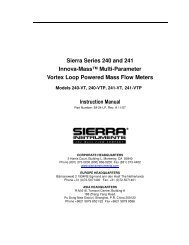
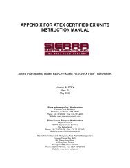
<strong>Sierra</strong> <strong>Instruments</strong> <strong>Instruction</strong> <strong>Manual</strong>SmartTrak ® 100 SeriesTHE SMARTTRAK FLOW SENSING PRINCIPLEThe operating principle of the SmartTrak instruments is based on heat transfer andthe first law of thermodynamics. During operation process gas enters theinstrument’s flow body and divides into two flow paths, one through the sensortube, and the other through the laminar flow bypass. The laminar flow bypass (oftencalled LFE which stands for “laminar flow element”) generates a pressure drop, P 1 –P 2 , forcing a small fraction of the total flow to pass through the sensor tube (m 1 ).Figure 1-1. Flow Paths through the InstrumentTwo resistance temperature detector (RTD) coils around the sensor tube direct aconstant amount of heat (H) into the gas stream. During operation, the gas massflow carries heat from the upstream coil to the downstream coil. The resultingtemperature difference (∆T) is measured by the SmartTrak microprocessor. Fromthis, SmartTrak calculates the output signal. Since the molecules of the gas carryaway the heat, the output signal is linearly proportional to gas mass flow.Figure 1-2. Flow Measuring Principle9
<strong>Sierra</strong> <strong>Instruments</strong> <strong>Instruction</strong> <strong>Manual</strong>SmartTrak ® 100 SeriesFigure 1-3. Sensor Temperature DistributionFigures 1-2 and 1-3 show the mass flow through the sensor tube as inverselyproportional to the temperature difference of the coils. The coils are legs of a bridgecircuit with an output voltage in direct proportion to the difference in the coils’resistance; the result is the temperature difference (∆T). Two other parameters, heatinput (H) and coefficient of specific heat (Cp) are both constant. Through carefuldesign and attention to these parameters, this output signal is made linear over thetransducer’s normal operating range (Figure 1-4). As a result, the measured flowthrough the sensor tube is directly proportional to the gas flow in the main body.Figure 1-4. Linear Range of the Transducer’s Output SignalIn the SmartTrak mass flow controllers, the gas which flows through themonitoring section is precisely regulated by the built-in electromagnetic valve. Thenormally closed valve is similar to an on/off solenoid valve, except that the currentto the valve coil, and hence the magnetic field, is modulated so that theferromagnetic valve armature, or valve plug, assumes the exact height above thevalve’s orifice required to maintain the valve’s command flow (set point). Theresult is excellent resolution.10
<strong>Sierra</strong> <strong>Instruments</strong> <strong>Instruction</strong> <strong>Manual</strong>SmartTrak ® 100 SeriesCHAPTER 2 INSTALLATIONWarning!Injury can result if linepressure exceeds themaximum rating of500 psig (34 barg).Before You Begin InstallationBefore installing the instrument, ensure that the installation site conforms to thespecific operating parameters recorded on the instrument’s Data Label. The DataLabel is mounted on the back of the instrument electronics enclosure (see sampleData Labels in Figure: 2-1). This is critical because each instrument is configuredfor a specific application range. Please review the gas or gases, the mountingorientation, the maximum flow range(s), the inlet and outlet pressure(s), and theoperating temperature(s). The line pressure should not exceed 500 psig (34 barg).The temperature should not exceed 122°F (50°C). The minimum operatingtemperature is 32°F (0°C) and ambient temperature is 0-50°C. If your applicationexceeds any of these parameters, contact your <strong>Sierra</strong> Sales Agent beforeinstallation. You may also contact one of <strong>Sierra</strong>’s Technical Support Centers.FACTORY USA: TOLL FREE: 800-866-0200 or PHONE: 831-373-0200 or FAX:831-373-4402 or EMAIL: service@sierrainstruments.comFigure 2-1: Examples of SmartTrak Data Labels11
<strong>Sierra</strong> <strong>Instruments</strong> <strong>Instruction</strong> <strong>Manual</strong>SmartTrak ® 100 SeriesPre-Installation Check List1. Double-check to be sure that the O-ring material used in yourinstrument is compatible with the gas to be measured. The O-ringmaterial used in your SmartTrak can be found in the Data Label. SeeAppendix A for a table of elastomer compatibility with a wide variety ofgases.2. <strong>Sierra</strong> strongly recommends you install an in-line filter upstream of theinstrument. Recommended filter size: 10 micron. A 10 micron filter isavailable from <strong>Sierra</strong> as an accessory. See Appendix B or contact your local<strong>Sierra</strong> distributor.3. Do not locate the instrument in areas subject to sudden temperaturechanges, excessive moisture or near equipment radiating significantamounts of heat. Be sure to allow adequate space for cable connectors andwiring.4. For controllers, use a properly sized pressure regulator. Make sure thepressure regulator is not too small or too big. There can be no restrictions(such as valves, tubing or pipe internal diameters, reducers, etc.) upstream ordownstream of the controller with a dimension that is less than the valveorifice diameter. To determine orifice diameter, consult the calibrationcertificate included with your instrument. If restricted, controller will notreach full scale.5. Output Signals: The SmartTrak has two analog outputs that are linearlyproportional to the gas mass flow rate, one voltage and one current. Choosefrom 0-20 mA or 4-20 mA for current plus one voltage signal: 0-5 VDC or0-10 VDC or 1-5 VDC. The output signals specified at time of order will beindicated on the data label. You may change among the current and thevoltage output signal at your discretion after receipt of the instrument usingthe Pilot Module or the SmartTrak Software (see Chapters 4 & 5). Changingthe output signals has no influence on the instrument’s accuracy.NOTE: For the SmarTrak 100 plus Compod, the 0-5 VDC I/O cannot beused. Only 4-20 mA I/O is available.6. The CAT-5 connector on the side of the SmartTrak is NOT an Ethernetconnector. It is for use with the optional Remote Pilot Module. Do not plugan Ethernet cable here as damage may result. Keep this connector covered ifpossible whenever it is not in use.7. The instrument has specific power supply requirements. See the tablelater in this chapter for a complete listing of power requirements.12
<strong>Sierra</strong> <strong>Instruments</strong> <strong>Instruction</strong> <strong>Manual</strong>SmartTrak ® 100 SeriesInstalling the Instrument—PlumbingSmartTrak instruments are supplied with compression, VCO ® , VCR ® , or femaleNPT process connections. To ensure a successful installation, inlet and outlet tubingshould be clean prior to plumbing the instrument into the system. The shipping capscovering the inlet/outlet fittings should not be removed until immediately beforeinstallation.Follow the installation instructions that are applicable to your instrument’s processconnection. Ensure that the tubing is free from burrs or sharp rims that may resultfrom cutting.CAUTION: Before use, all plumbing should be checked carefully for leaks,especially at the connecting fittings. All instruments are leak-tested prior toshipping. It is not a requirement to leak test your instrument. Do not use liquidleak detectors such as Snoop ® to search for leaks inside or outside theSmartTrak. Instead, monitor pressure decay.Compression Fittings1. Position the instrument with the flowdirection arrow pointing in the directionof flow.2. Verify the position of the front and back ferrule. Insert the tubing into thefitting. Be sure that the tubing rests firmly on the shoulder of the fitting andthat the nut is finger-tight. Scribe the nut at the six o’clock position.3. While holding the fitting body steady with a backup wrench, tighten the nut1-1/4 turns, watching the scribe mark make one complete revolution andcontinue to the nine o’clock position. For 1/16-inch, 1/8-inch and 3/16-inch(2, 3 and 4 mm) sizes, tighten only 3/4 turns from finger-tight. Do not overtighten!4. If you use flexible tubing (Example: Polyflow) use an “Insert” (seewww.swagelok.com)5. Check the system’s entire flow path thoroughly for leaks. Do not use liquidleak detectors. Instead, monitor pressure decay. Exposing the instrument toleak detector fluid may cause damage.VCO Fittings1. Position the instrument with the flow direction arrow pointing in thedirection of flow.13
<strong>Sierra</strong> <strong>Instruments</strong> <strong>Instruction</strong> <strong>Manual</strong>SmartTrak ® 100 SeriesInstalling your Instrument—Mechanical MountingMounting your InstrumentThe base plate or bottom of the instrument has 4 mounting holes. Two are SAEthread and two are metric thread. For location and dimensions, please see AppendixE.Your SmartTrak instrument is made from premium 316 stainless steel. As a result, itmay require substantial mounting brackets to properly support its weight. Exercisecaution when installing to avoid damage or injury.Mounting the Optional Remote Pilot ModuleIf you have the optional Remote Pilot Module control unit, you have severalmounting options.1. Wall or Panel mounting—your Remote Pilot Module may be mounted to aflat surface using the supplied plate and 2 special “shoulder” screws.Simply screw the shoulder screws into the plate. Then, attach the plate tothe wall by driving 2 screws (not included) through the 2 large central holes.MAKE SURE THE UP ARROW IMPRINTED ON THE MOUNTINGBRACKET POINTS UPWARD. Your Remote Pilot Module will slip ontothe shoulder screws. Push against the plate and then down. To remove,push up and pull. Attach the CAT-5 cable to the socket on the bottom of theRemote Pilot Module.2. Rack mounting—to mount your Remote Pilot Module to a standard 19”laboratory rack, first purchase a “blank” panel from your industrial supplier.Decide where the Remote Pilot Module will be attached, then follow theprocedure listed above for wall mounting. When you are ready, insert theCAT-5 cable into the socket in the Remote Pilot Module.3. Desktop mounting—the Remote Pilot Module will sit on a desk in afashion that makes it convenient to view and operate. Insert the CAT-5cable into the socket in the back of the Module. Use the cable as a“kickstand.” Gently bend the cable to recline the Remote Pilot Module toan angle suitable for easy viewing. Alternately, you can lay the RemotePilot Module on its back and insert the CAT-5 cable into the socket in thebottom.15
<strong>Sierra</strong> <strong>Instruments</strong> <strong>Instruction</strong> <strong>Manual</strong>SmartTrak ® 100 SeriesInstalling your Instrument—Electrical ConnectionsAll electrical connections for your SmartTrak instrument are made on the left (inlet)side panel. See Figure 2-2: SmartTrak Connections below for the location of allconnections. Note that the CAT-5 connector is not an ethernet connector.CAT 5HD DB 15Figure 2-2: SmartTrak connections16
<strong>Sierra</strong> <strong>Instruments</strong> <strong>Instruction</strong> <strong>Manual</strong>SmartTrak ® 100 SeriesSmartTrak is provided with a high density 15-pin D Connector called an “HD DB-15” located on the side of the enclosure and either one of our optional preassembledcommunications cables or an empty mating connector. Power must besupplied to the HD DB-15 connector. Other features may be accessed there as well.The pin numbers and assignments for the HD DB-15 connector are shown in Figure2-3: HD DB-15 Connector Pin Configuration (on the instrument). Thecorresponding colors of the optional communication cable wires and the functionsof each are listed in Figure 2-4: Wiring Definitions for Optional CommunicationCable. The connections for input power, analog output signal and analog inputsignal (controllers only) are all made at the HD DB-15 connector. There is asecond copy of these 2 figures in Appendix D for your convenience17
<strong>Sierra</strong> <strong>Instruments</strong> <strong>Instruction</strong> <strong>Manual</strong>SmartTrak ® 100 SeriesFigure 2-3: HD DB-15 Connector Pin Configuration (on the instrument)Figure 2-4: Wiring Definitions for Optional Communication CablePin # Wire Color in Cable Function1. Brown Analog Ground/Output2. Red 0-5 VDC Output (or 0-10, 1-5 VDC)3. Orange Analog Ground/RS2324. Pink Valve Override Purge5. Yellow Power Return (-)6. Green Power Input (+)7. Green/White RS-232 Transmit (out)8. Blue Setpoint9. Purple Not Used10. Gray Analog Ground/Setpoint11. White Reference Voltage(5 VDC External Setpoint & Valve Purge)12. Black Valve Override Close13. Brown/white RS-232 Receive (in)14. Red/white 4-20 mA Output15. Red/Black Not UsedShield Wire(no insulation)Chassis (Earth) GroundNOTE: Pins 1, 3, and 10 are connected together inside theinstrument. Do not tie these grounds together outside theinstrument. Must have one connection per analog ground.Recommended use listed.18
<strong>Sierra</strong> <strong>Instruments</strong> <strong>Instruction</strong> <strong>Manual</strong>SmartTrak ® 100 SeriesInstrument Power:The SmartTrak requires a 15-24 VDC power supply. If you are using the powersupply supplied by <strong>Sierra</strong>, connect it to the 15-pin HD DB-15 connector on the side ofthe instrument. If you are supplying your own power source, it must be a regulated15-24 VDC with ripple not to exceed 100 mV peak-to-peak. It must be capable ofproducing the current specified for the appropriate voltage shown in Figure 2-5: PowerSupply Requirements. Apply power as follows: positive (+) to the green (pin 6) andnegative (-) to the yellow (pin 5) wires. The instrument is polarity sensitive. If youreverse this wiring, the instrument will not be damaged, but it will not function.Instrument Grounding:The SmartTrak has very high levels of RFI and EMI shielding built into the metalelectronics cover (meets or exceeds the CE Standard EN 61326-1; 2006). To maintainthe integrity of this CE rating, it is critical that a path be provided for any residualinternal noise to exit the instrument or it may register on the outputs. Groundingprovides this path.To properly ground your instrument, secure the chassis to solid earth ground using themounting holes on the bottom of the flow body. If the instrument will be used withoutpermanent mounting (on a laboratory bench, for instance) then, using the providedcable, connect the shield wire (no insulation) to earth ground in your facility. If youpurchased a <strong>Sierra</strong> power supply, a ground wire is provided for your convenience.Figure 2-5: Power Supply RequirementsInstrument Type Recommended InputVoltageMinimum CurrentRequired (mA)M100L Meter 15-24 VDC (+ 10%) 230M100M Meter 15-24 VDC (+ 10%) 230M100H Meter 15-24 VDC (+ 10%) 230C100L Controller 24 + 10% VDC 500C100M Controller 24 + 10% VDC 800C100H Controller 24 + 10% VDC 1260NOTE: The Compod adds an additional 100mA to the ST2 current ratings.CAUTION: This instrument is not a loop-powered device! Do NOT apply powerto the 4-20 mA output or input connections.19
<strong>Sierra</strong> <strong>Instruments</strong> <strong>Instruction</strong> <strong>Manual</strong>SmartTrak ® 100 SeriesAnalog Output Signals: Output Signal—Voltage: Measure the voltage output signal across the red (pin 2)wire and any of the analog grounds: brown (pin 1), orange (pin 3) or gray (pin 10).The minimum load is 1000 Ohms. We recommend pin 1. DO NOT USE THE SAMEANALOG GROUND FOR CURRENT OUTPUT, SETPOINT OR RS232.Output Signal—Current: Measure the current output signal, 4-20 mA or 0-20 mA,across the red/white stripe (pin 14) wire and any of the analog grounds: pin 1, 3, or10. The maximum load is 500 Ohms. We recommend pin 1. DO NOT USE THESAME ANALOG GROUND FOR VOLTAGE OUTPUT, SETPOINT OR RS232.For Mass Flow Controllers, the following analog features are alsoavailable at the HD DB-15 connector:• Setpoint: To transmit an analog setpoint, supply the voltage or current signal (checkthe data label and/or setting) across the blue (pin 8) wire and pin 10.• Valve Close: To force the valve closed, connect the black (pin 12) wire to pin 10• Purge: To force the valve to its maximum open position which we call “Purge,”connect the pink (pin 4) wire to the white (pin 11) wire. Note that this will allowmuch greater flow than the rated full-scale value.For Digital Communication Using Your Personal Computer:You can communicate with your instrument using the SmartTrak Software package andyour PC running the Windows operating system. Simply connect the light green (pin 7)wire, the brown/white stripe (pin 13) wire and one of the analog grounds (pin 1,3, or 10)to a standard DB-9 connector according to Figure 2-6: Digital Communication.Figure 2-6: Digital CommunicationRS-232 Transmit (pin 7) to DB-9 pin #2RS-232 Receive (pin 13) to DB-9 pin #3Analog ground (pin 3) to DB-9 pin #520
<strong>Sierra</strong> <strong>Instruments</strong> <strong>Instruction</strong> <strong>Manual</strong>SmartTrak ® 100 SeriesNOTE: Transit and Receive may need to be reversed, depending on which type ofdevice or cable is connected. (No damage will result—attempt communication afterreversal.With the connections in Figure 2-6 in place, plug the DB-9 connector into an appropriateserial port on your PC.To minimize the potential for RF interference, it is recommended to shield these wires.Use a metal DB-9 connector and connect one end of the shield to the DB-9 shell and theother end to the outer shell of the SmartTrak HD DB-15 connector.CAUTION: The CAT-5 connector on the side of the SmartTrak is NOT an Ethernetconnector. It is for use with the optional Remote Pilot Module or CRN cable. Do notplug an Ethernet cable here as damage may result.21
ATP: 1Fiscal Year: 2012STIP for FY 2012-2015Seq #RouteSystem Project Number Agency Description Miles ProgramType of WorkProposedFundsTotalFHWA AC FTA TH Other1 BB TRF-0005-12 MNDOT SECT 5311: AEOA TRANSIT OPERATING ASSISTANCE 0.0 OB OPERATE BUS FTA 5,075,648 0 0 1,882,000 0 3,193,6482 BB TRF-0005-12-JA MNDOT SECT 5316: ARROWHEAD ECONOMIC OPPORTUNITY0.0 JA OPERATE BUS FTA 240,000 0 0 120,000 0 120,000AGENCY INC.,- RURAL RIDES OPERATING3 BB TRF-0005-12-JB MNDOT SECT 5316: ARROWHEAD ECONOMIC OPPORTUNITY0.0 JA OPERATE BUS FTA 225,000 0 0 180,000 0 45,000AGENCY INC.,- RURAL RIDES-MOBILITY MANAGEMENT4 BB TRF-0016-12A DULUTH TRANSIT SECT 5307: DULUTH DIAL-A-RIDE TRANSIT OPERATING 0.0 B9 OPERATE BUS LF 575,960 0 00 0 575,960AUTHORITY ASSISTANCE5 BB TRF-0016-12B DULUTH TRANSIT SECT 5307: DULUTH TRANSIT OPERATING ASSISTANCE 0.0 B9 OPERATE BUS FTA 10,213,005 0 0 1,300,000 0 8,913,005AUTHORITY REGULAR ROUTE & PREVENTATIVE MAINTENANCE6 BB TRF-0016-12C DULUTH TRANSIT SECT 5307: DULUTH TRANSIT CAPITAL0.0 B9 BUS GRANT FTA 699,856 0 0 559,885 0 139,971AUTHORITYCAPITALIMPROVEMENT7 BB TRF-0016-12-JA DULUTH TRANSIT SECT 5316: JARC URBAN OPERATING FUNDS FOR0.0 JA OPERATE BUS FTA 383,000 0 0 191,500 0 191,500AUTHORITY DULUTH TRANSIT AUTHORITY8 BB TRF-0022-12 MNDOT SECT 5311: HIBBING TRANSIT OPERATING ASSISTANCE 0.0 OB OPERATE BUS FTA 257,125 0 0 74,200 0 182,9259 BB TRS-0005-12 MNDOT ARROWHEAD TRANSIT-PURCHASE 5 BUSES - (CLASS 500) 0.0 TR PURCHASE BUS STP 605,000 484,000 00 0 121,00010 BB TRS-0016-12 DULUTH TRANSIT DTA-PURCHASE 10 BUSES TOTAL, 5 WILL BE HYBRID 0.0 TR PURCHASE BUS STP 4,618,180 3,694,544 00 0 923,636AUTHORITY (CLASS 700)11 RR 38-00107 MNDOT CSAH 11, W OF TWO HARBORS, UPGRADE TO GATES 0.0 SR RAILROADRRS 250,000 225,000 00 0 25,000SIGNALS12 RR 69-00189 MNDOT ST LOUIS CO RD 874, GRAND LAKE RD, INSTALL GATES 0.0 SR RAILROADRRS 225,000 202,500 00 0 22,500SIGNALS13 RR 69-00190 MNDOT ST LOUIS CO RD 452, IRON JCT RD, ST, INSTALL GATES 0.0 SR RAILROADRRS 250,000 225,000 00 0 25,000SIGNALS14 CSAH 10 001-610-022 AITKIN COUNTY **MN140** JCT TH 169 TO JCT TH 232, GRADING & BASE 7.1 RC GRADINGHPP 1,930,000 1,544,000 00 0 386,00015 PED/BIKE 009-591-002 CARLTON COUNTY **SRTS** IN THOMSON TOWNSHIP - PE FOR 10 FT WIDETRL TO CONNECT ESKO SCHOOLS TO LARGERESIDENTIAL AREA SITUATED ALONG 4 LANE HWY (SEE009-591-003 FOR CONST PROJ)0.0 BT PED./BIKEIMPROVEMENTSRTS 54,200 54,200 00 0 016 TWN 009-596-005 TWIN LAKES **MN201** CONSTRUCT PFEIFER ROAD, REMOVE 10 FT 0.0 RC GRADE AND HPP 543,464 181,217 00 0 362,247TOWNSHIP RAISED CROSSING, TWIN LAKES TWPSURFACESeptember 2011Project Listing Page III - 4 of 172
<strong>Sierra</strong> <strong>Instruments</strong> <strong>Instruction</strong> <strong>Manual</strong>SmartTrak ® 100 SeriesAnalog Operation, Mass Flow ControllerAfter your instrument is installed and the system has undergone a complete leakcheck as discussed in detail in Chapter 2, follow these steps:1. The valve will remain closed until power is supplied. See Chapter 2 forwiring instructions. Remember that the valve in the SmartTrak is not a positiveshut-off device. When power is applied, the flow control valve will operate perany instructions it receives. When the SmartTrak is delivered, the valve will bein the Automatic (Normal) state and the Pilot Module or analog signal willprovide the correct zero setpoint reference for the instrument. As a result, thevalve will be closed. However, upon subsequent power-ups, the valve willreturn to the state it was in the last time the instrument was operated.CAUTION: If you do not know the value of the setpoint or the valve stategiven to the SmartTrak when it was last operated, you must assume thatthe valve will open when power is applied. Take necessary precautions.You may use the Pilot Module or the SmartTrak Software to check thesetpoint or the valve state currently on your instrument. See Chapter 4 orChapter 5 for information on Setpoint and Valve State.2. Power Your Instrument: Provide adequate power per Figure 2-5. Apply powerusing <strong>Sierra</strong>’s power supply or your own power source. The green LED at thetop of the inlet side will light to confirm power. If your instrument has a PilotModule, it will begin its start-up cycle. See Chapter 4 for details on PilotModule operation. NOTE: It is highly recommended you connect power to theSmartTrak, and then power your supply (plug into wall or switch on). Theopposite may cause the unit to take longer to power on. Let the instrument warmup for at least 15 minutes for optimal performance.3. Adjust the controller setpoint to the desired flow rate by supplying anappropriate signal (mA or VDC). The effective control range of the unit is 2%to 100% of the calibrated full scale flow range. Automatic shut-off occurs at1.9% of the factory full scale calibrated range unless specifically modified attime of order. SmartTrak will immediately begin accurately monitoring andcontrolling the gas mass flow rate. Let the instrument warm up for at least 15minutes for optimal performance.Your SmartTrak instrument is now ready for use!23
<strong>Sierra</strong> <strong>Instruments</strong> <strong>Instruction</strong> <strong>Manual</strong>SmartTrak ® 100 SeriesSmartTrak FeaturesSetpoint AdjustmentThe setpoint (command) input signal you supply to SmartTrak must be a directlinear representation of 0% to 100% of the mass flow full-scale value. Apply thesetpoint signal from pin 8 to any of the analog grounds (see Chapter 2 for wiringdetails). A setpoint value of 0 VDC or mA (or 1 VDC or 4 mA) will regulate theflow to 0% and a setpoint value of 5.00 VDC (or 10 VDC or 20 mA) will adjust theflow to 100% of the instrument’s full scale range.When the setpoint (command) signal is applied, the flow controller will reach thesetpoint value within two seconds to within ±2% of the selected flow rate.CAUTION: DO NOT LEAVE A SETPOINT APPLIED FOR ANEXTENDED PERIOD OF TIME TO A CONTROLLER WHEN THEGAS SUPPLY IS SHUT OFF OR BLOCKED. Damage may result and theinstrument will become hot to the touch. Instead, see below for use of the“Valve Close” feature which allows you to disable the valve whilemaintaining the setpoint signal. This may be set by the Pilot Module, theSmartTrak Software, or an external analog signal.Changing the Output or Setpoint SignalsTo modify the analog output or setpoint signals (from 4-20mA to 0-10Vdc, forexample), you must use the Pilot Module or the SmartTrak Software. The datalabel will indicate the form these signals had when the instrument was lastcalibrated. We strongly recommend that you adapt the data label if theconfiguration is changed for future reference. See Chapter 4 or 5 for the necessaryprocedure.Over-Range ConditionIf the mass flow rate exceeds the full-scale range listed on the SmartTrak data label(see samples on page 2-1), the output signal will measure above full-scale.However, the device has not been calibrated for flows in excess of the calibratedfull scale value and the value will be both non-linear and inaccurate if an over-rangecondition exists. Please be aware that the analog outputs can exceed full scale by asmuch as 20%, or more.Once the over-range condition has been removed, it may take up to 30 seconds forthe SmartTrak to recover and resume normal operation. An over-range conditionwill not harm the instrument.24
<strong>Sierra</strong> <strong>Instruments</strong> <strong>Instruction</strong> <strong>Manual</strong>SmartTrak ® 100 Series<strong>Manual</strong> Valve Override—Valve Close<strong>Manual</strong> valve override is provided for all <strong>Sierra</strong> mass flow controllers. This featureincludes both a valve close command and a valve maximum open command (calledpurge). When the valve is directed to close or to purge, it will no longer respond toa setpoint command.FOR VALVE CLOSE: connect pin 12 to analog groundRemember that the valve in the SmartTrak is not a positive shut-off device.The Controller will return to normal automatic operation about 4 secondsafter pin 12 is left floating.<strong>Manual</strong> Valve Override—Valve Purge FunctionThe purge function opens the controller valve completely for the purpose of quicklyflushing unwanted gas from the flow path. When the valve is opened for purging, itallows flows far in excess of the rated full scale of the controller.FOR VALVE PURGE: connect pin 4 to pin 11.CAUTION: PURGE MODE ALLOWS FAR MORE GAS TO FLOW THROUGHTHE CONTROLLER! BEFORE USING VALVE PURGE OPERATION, INSUREPROPER DOWNSTREAM CAPACITY AND VENTILATION.Caution!IMPORTANT NOTES ABOUT PURGINGPurging Non-Reactive Gases:Purge your SmartTrak with clean, dry nitrogen for a minimum of two hours.Purging Reactive Gases:One of the following methods may be used: Cycle purge. This is done by alternately evacuating and purging theinstrument for 2 to 4 hours with clean, dry nitrogen. Purge the instrument with clean, dry nitrogen for 18 to 24 hours. Evacuate the instrument for 18 to 24 hours.25
<strong>Sierra</strong> <strong>Instruments</strong> <strong>Instruction</strong> <strong>Manual</strong>SmartTrak ® 100 SeriesIMPORTANT SAFETY NOTES ABOUT PURGINGWARNING: When toxic or corrosive gases are used,purge unit thoroughly with inert dry gas beforedisconnecting from the gas line to prevent personnelfrom being injured when coming in contact with theinstrument.WARNING: If an instrument used with a toxic orcorrosive gas is returned to the factory, a MaterialSafety Data Sheet (MSDS) must be enclosed &attached to the outside of the box to alert <strong>Sierra</strong>personnel of the potential hazard. Also, make sure theinlet & outlet are securely sealed.26
<strong>Sierra</strong> <strong>Instruments</strong> <strong>Instruction</strong> <strong>Manual</strong>SmartTrak ® 100 SeriesCHAPTER 4: Digital Operation with Pilot ModuleYour SmartTrak instrument may be operated in three different ways:THREE CONTROL OPTIONSA. Analog Input/Output Operation (Chapter 3): Using analoginput/output signals at the HD DB-15 connector.B. Digital Operation with Pilot Module (This Chapter): Using theoptional Pilot Module.C. Digital Operation with RS-232 and SmartTrak Software (Chapter5): Using the RS-232 SmartTrak Software package and a computer runningthe Windows operating system.This chapter will discuss the second of these—Digital Operation with the optionalPilot Module. Please see alternate chapters for other options.Although you have chosen to use the optional Pilot Module, please note that all theAnalog control functions are still available on your instrument. Consult Chapter 3for details on Analog operation. Also, computer control using the RS-232communication is available. See Chapter 5 for details on operation with a computer.CAUTION—If RS-232 digital communication is to be used in conjunction with thePilot Module, the HD DB15 connector must be properly wired with a three wireserial DB9 cable to your computer. Often, this is done with the same HD DB15 thatsupplies power to your instrument. You can run both RS-232 communication andPilot Module communications in parallel, but the unit will only respond to one set ofcommands at a time. DO NOT attempt to control the unit simultaneously with boththe Pilot Module and the computer, this can lock up the unit.Introduction to Pilot Module Features and CapabilitiesThe optional Pilot Module functions as both display and a control unit for yourSmartTrak instrument. The standard Pilot Module is available mounted directly onthe face of your instrument or as a handheld / remote mountable control interfaceattached to the SmartTrak via a detachable cable.If your instrument has a standard Pilot Module mounted locally on the face of theunit, no additional set-up is required. See picture below.27
<strong>Sierra</strong> <strong>Instruments</strong> <strong>Instruction</strong> <strong>Manual</strong>SmartTrak ® 100 SeriesOn the other hand, if your instrument has a Remote Pilot Module, attach one end ofthe included Category 5 (CAT 5, also called RJ-45) connecting cable into the jackat the top of the instrument’s left side, immediately above the HD DB-15 connector.Next, place the other end into one of the two matching jacks on the Pilot Module.For your convenience, <strong>Sierra</strong> has provided two jacks—one on the back and one onthe bottom of the Remote Pilot Module. You may use whichever jack is mostconvenient for your application as they both have identical functions.The Pilot Module includes a large LCD graphic display screen and six buttons. TheLCD will show a variety of information and the buttons can be used to view andmodify this information. The convenient buttons are:Left arrowRight arrowUp arrowDown arrowEnter buttonEscape button28
<strong>Sierra</strong> <strong>Instruments</strong> <strong>Instruction</strong> <strong>Manual</strong>SmartTrak ® 100 SeriesThese are shown in the photo below:Up, DownLeft, RightEscapeEnterPilot Module Operation, Mass Flow MeterAfter your instrument is installed and the system has undergone a complete leak checkas discussed in detail in Chapter 2, follow these steps:Caution!The SmartTrak isnot a loop-powereddevice. Do notapply power to the4-20 mA outputs.1. Power Up Your Instrument: Apply power to your instrument. See Chapter 2,Figure 2-5: Power Supply Requirements. When power is first applied, the PilotModule will display:Version2.04XRead ParametersAssuming no gas is flowing, after another 5-10 seconds the display will read:Mass Flow0.000 sl/m29
<strong>Sierra</strong> <strong>Instruments</strong> <strong>Instruction</strong> <strong>Manual</strong>SmartTrak ® 100 SeriesAirNOTE: If gas is flowing the Pilot Module will immediately begin to accuratelydisplay the gas mass flow rate on the LCD panel. If you have chosen alternate unitsor another gas, the display will show the selected units instead of the above.2. Open the gas supply: SmartTrak is now ready to monitor the gas mass flowrate. Let the instrument warm up for at least 15 minutes for optimalperformance.Your SmartTrak instrument is now ready for use!Pilot Module Operation, Mass Flow ControllersAfter your instrument is installed and the system has undergone a complete leakcheck as discussed in detail in Chapter 2, follow these steps:1. The valve will remain closed until power is supplied. See Chapter 2for wiring instructions.CAUTION: Remember that the valve in the SmartTrak is not a guaranteedpositive shut-off device. For dangerous applications, <strong>Sierra</strong> recommends use ofan external shut-off safety valve.When power is applied, the flow control valve will operate per the instructions itreceives from the Pilot Module. When the SmartTrak is delivered, the valve will bein the Automatic (Normal) state and the Pilot Module will provide the correct zerosetpoint reference. As a result, the valve will be closed. However, the valve willreturn to the state it was in the last time the instrument was operated.WARNING: If you do not know the setpoint or the valve state of the MassFlow Controller before it was shut down, you must assume that the valve willopen when power is applied. TAKE NECESSARY PRECAUTIONS.2. Power Up Your Instrument: Apply power to your instrument using<strong>Sierra</strong>’s power supply or your own input power source. See Chapter 2,Figure 2-5: Power Supply Requirements. When power is first applied,the Pilot Module will display:Version2.04XRead ParametersIf no gas is flowing, after another 5-10 seconds the display will read:30
<strong>Sierra</strong> <strong>Instruments</strong> <strong>Instruction</strong> <strong>Manual</strong>SmartTrak ® 100 SeriesMass Flow0.000 sl/mAirNOTE: If gas is flowing and the Pilot Module has a setpoint greater than zero, itwill immediately begin to accurately display the gas mass flow rate on the LCDpanel. If you have chosen alternate units or another gas, the display will show theselected units instead of those above.3. Open the gas supply. SmartTrak is now ready to monitor and controlthe gas mass flow rate. The display will show 0.000 until it is given asetpoint. Let the instrument warm up for at least 15 minutes for optimalperformance.Your SmartTrak instrument is now ready for use!CAUTION: DO NOT LEAVE A SETPOINT APPLIED FOR AN EXTENDEDPERIOD OF TIME TO A CONTROLLER WHEN THE GAS SUPPLY ISSHUT OFF OR BLOCKED. Damage may result and the instrument will becomehot to the touch. Instead, see below for use of the “Valve Close” feature whichallows you to disable the valve while maintaining the setpoint signal. This may beset by the Pilot Module, the SmartTrak Software, or an external analog signal.Using the Pilot Module Menus & User InterfaceThe features of the Pilot Module can be considered in three groups:1 Upper Level Screens: display information (no password is required to view thisinformation). These include: Mass flow rate Gas (10 options pre-programmed) Engineering units (mass per unit time) Current Setpoint with units Source of Setpoint (analog or digital and type) Valve operation mode (normal, valve close or purge) Current meter full scale value with units (user selectable)31
<strong>Sierra</strong> <strong>Instruments</strong> <strong>Instruction</strong> <strong>Manual</strong>SmartTrak ® 100 Series2 Lower Level Screens: permit changes to instrument operation. They are passwordprotected. These include: Setpoint value Engineering units Gas Valve operation Source of the setpoint signal Form of the output signals Full scale of the instrument Password Zero Span3 Maintenance Features: Re-boot the SmartTrak microprocessor. Press the LEFT ARROW, DOWNARROW, ENTER, AND ESCAPE keys at the same time. Move the decimal point. Navigate to the “change the setpoint” menu. PressENTER to make one of the digits flash. While it is flashing, press ESCAPE at the sametime you press LEFT ARROW or RIGHT ARROW. Return all parameters to the factory default values. Navigate to the“Change the Setpoint” menu. Press LEFT ARROW, UP ARROW, and ENTER at thesame time. Choose “yes” to restore factory default settings. If you are trying to navigate using the pilot but the message appears,“Must be in Pilot Mode,” use the LEFT ARROW from this screen to navigate to the“Change Setpoint Source” and change to “Pilot / RS-232.” Escape and try again.32
<strong>Sierra</strong> <strong>Instruments</strong> <strong>Instruction</strong> <strong>Manual</strong>SmartTrak ® 100 SeriesMap of the Pilot Module InterfaceThe Pilot Module user interface is presented below in a graphical format. Once youhave some familiarity with the user interface, you may find you want to make acopy of this and keep it with the instrument for reference. You can find a largerversion of this Flow Chart in Appendix C.33
<strong>Sierra</strong> <strong>Instruments</strong> <strong>Instruction</strong> <strong>Manual</strong>SmartTrak ® 100 SeriesThe seven Upper Level Screens display a variety of information. You are able tomove between the screens by pressing the left or right arrows. No password isrequired for the Upper Level Screens.Mass Flow ScreenWhen the instrument is powered up, or whenever the escape button is pressed, italways returns to the Mass Flow Screen. This screen displays the mass flow rate,the engineering units and your gas choice. It looks something like this:Mass Flow0.000 sl/mAirSetpoint ScreenPushing the right arrow takes you to the Setpoint Screen. The Setpoint Screendisplays the current setpoint given to the controller, the engineering units and thesource of the setpoint signal.The source of the setpoint can be: Pilot Module/RS-232 4-20 mA 1-5 Vdc 0-5 Vdc 0-10 VdcFor operation with the Pilot Module, the display will look something like this:Setpoint10.00 sl/mPilot Module/RS-232If this screen does not show “Pilot Module/RS-232” at the bottom, you will not beable to give the controller a setpoint command from the Pilot Module because theinstrument is waiting for an analog setpoint. See section below titled “ChangeSetpoint Source Screen” to change the source of the setpoint signal. Alternately,you may supply an analog setpoint to the HD DB-15 connector (see Chapter 3).34
<strong>Sierra</strong> <strong>Instruments</strong> <strong>Instruction</strong> <strong>Manual</strong>SmartTrak ® 100 SeriesValve Position Screen (Mass Flow Controllers only)Pushing the right arrow again takes you to the Valve Position Screen, if you have aMass Flow Controller. This screen will display the current state of the SmartTrakvalve.The state of the valve can be:1. Closed (Remember that the SmartTrak is not a positive shut-off device).2. Purge--Maximum Open (recommended 120% of the calibrated full scalevalue, but can be much more and can be dangerous)3. Automatic (the normal position, where the controller responds to a setpointsignal).WARNING: The flow rate in Purge is much greater than thecalibrated full scale value and as a result can be dangerous.For normal operation of the flow controller, this screen should display:ValveAutomaticNormalIf this is visible, the instrument will automatically control flow as soon as a setpointis given to it. If this screen displays Closed or Purge, the instrument has beenplaced into an override position and it will not respond to any setpoint signal. Thevalve state may be changed using the “Change Valve Operation” as described onpage 4-16.Full Scale ScreenPressing the right arrow again takes you to the Full Scale Screen. This screendisplays the current full scale value of the instrument with engineering units. It alsodisplays the gas. Note that this is not necessarily the factory calibrated full scalevalue. The screen will display:Full Scale10.00 sl/mNitrogenTo change the full scale value, see the section below titled “Change Full ScaleScreen.” Pressing the right arrow again takes you back to the Mass Flow Screen.35
<strong>Sierra</strong> <strong>Instruments</strong> <strong>Instruction</strong> <strong>Manual</strong>SmartTrak ® 100 SeriesLower Level Screens (Changing Parameters)Getting to the Lower Level Screens:Your instrument is password protected so that unauthorized personnel will beunable to change the operating parameters of SmartTrak. To enter the Lower LevelScreens at any time you must first supply the correct password.Password Screen: By pressing the “enter” key from any of the Upper LevelScreens you will come to the Password Screen. (If you do not know if you are in anUpper Level Screen, press escape and you always automatically go to the MassFlow Screen in the Upper Level) The display will show:Enter Password0000The first digit will blink. At this point, you must enter the correct password to gainaccess to the Lower Level Screens. If the instrument is being operated for the first time or if no password has everbeen set on the instrument: You can use the factory default password. The factorydefault password is “0000.” To proceed to the Lower Level Screens by using thefactory default password, simply press the “enter” key a second time. If you wantrapid access to permit regular changes to your instrument and you do not desire apassword, this is the fastest way to enter the lower level. If You Have a Password: If you have already set a password, enter it now. Toenter the password, push the up arrow to increase the blinking digit or the downarrow to decrease the blinking digit. To move to the next digit, press the left orright arrow and repeat the process. When you have selected your four digitpassword, press the enter key. If You Want to Set a New Password: If you want to change the password, youmust first get to the Lower Level Screens. Proceed by entering your knownpassword or if no password has ever been set on the instrument, us the factorydefault password. Follow the instructions in the “Change Password Screen” sectionfound later in this chapter.If the password you have entered is correct, you will enter the Lower Level at theChange Setpoint Value Screen.36
<strong>Sierra</strong> <strong>Instruments</strong> <strong>Instruction</strong> <strong>Manual</strong>SmartTrak ® 100 SeriesIf the password is not correct, the display will show:Access DeniedPress any buttonTo continueWhen you press any button, you will return to the Mass Flow Screen in the Upper Level.Press the “enter” key to try again.LOST PASSWORDS & GENERAL CUSTOMER SERVICE: If you lose yourpassword, it will be necessary to contact one of <strong>Sierra</strong>’s Technical Support Centers.Email Customer Service: service@sierrainstruments.comFACTORY USA Customer Service:TOLL FREE: 800-866-0200PHONE: 831-373-0200FAX: 831-373-4402EMAIL: service@sierrainstruments.comEuropean Customer Service:PHONE: +31 72 5071400FAX: +31 72 5071401EMAIL: service@sierra-instruments.nlAsia Customer Service:PHONE: + 8221 5879 8521FAX: +8621 5879 8586EMAIL: www.sierra-asia.com37
<strong>Sierra</strong> <strong>Instruments</strong> <strong>Instruction</strong> <strong>Manual</strong>SmartTrak ® 100 SeriesMaking Changes Using the Lower Level Screens:The ten Lower Level Screens are at the heart of Dial-A-Gas®, allowing youcomplete control of your SmartTrak instrument. It is possible to make severalchanges on different Lower Level Screens before exiting.For example, you could change between one of the ten pre-programmed gases,change the engineering units, and change the setpoint all in one visit to the LowerLevel Screens. The SmartTrak will make each adjustment as you complete it. Atany time, you may press the escape button to return to the Upper Level.Change Setpoint Value ScreenThis screen is the entry point to the Lower Level. As soon as a correct password isentered, you will arrive here. If you are already in the Lower Level Screens, pushthe right or left arrow until you reach the Change Setpoint Value screen. Thedisplay will show:Change Setpoint00.00 sl/mAirThis is the position where you can change the setpoint value of the mass flowcontroller. To make a change to the displayed value, press the enter key. The firstnumber in the display will blink. Use the up and down arrows to change the valueof this digit or the left and right arrows to move to another digit. For example, ifyou wish to enter a setpoint of 12.5 sl/m, push the “up” arrow once when the firstdigit is blinking. You will see:Change Setpoint10.00 sl/mAirNext, press the “right” arrow so that the second digit blinks. Push the up arrowtwice. You will now see:Change Setpoint12.00 sl/mAirPress the right arrow again. The first digit after the decimal point will now blink.Press the up arrow 5 times until you see:38
<strong>Sierra</strong> <strong>Instruments</strong> <strong>Instruction</strong> <strong>Manual</strong>SmartTrak ® 100 SeriesChange Setpoint12.50 sl/mAirNow that you have made your selection, press the enter key. The display from ourexample will show:Change Setpoint12.50 sl/mAirIf you are finished or wish to observe the changes you have made on the LCDpanel, press the escape key to return to the Upper Level Mass Flow Screen.If you prefer to make additional changes, use the left and right arrow keys to moveto other Lower Level Screens.Caution!The SmartTrak will notallow you to enter asetpoint greater than thecurrent full scale valueset on the instrument.Note: If you enter a Setpoint that exceeds the full scale value (displayed in the “FullScale” screen in the Upper Level), the SmartTrak will automatically modify thisvalue to equal the current full scale value. For example, if the current full scale valueof your instrument is 10 slpm and you have entered a setpoint of 15 slpm, theSmartTrak will modify your setpoint to 10 slpm when you implement the change.The Setpoint Value screen will show 10 slpm, not 15 slpm.Change Units ScreenIf you are already in the Lower Level Screens, push the right or left arrow until youreach the Change Units screen. To get to this screen at any time, Press Escape—Press Enter—type password and Press Enter. Then, press the Right or Left arrowuntil you reach the Change Units Screen.The display will show:Change Unitssl/m39
<strong>Sierra</strong> <strong>Instruments</strong> <strong>Instruction</strong> <strong>Manual</strong>SmartTrak ® 100 SeriesIf you wish to change the engineering units, press the enter button at this point. The“mass units” will begin to blink. Use the up or down arrows to select an alternateunit. You can choose from the following mass units:slNLgkglbsccNccSCFNM 3SM 3When you are satisfied, push the left or right arrow. You will now see the “timeunit” blink. Use the up or down arrows to select your choice of time units. You canchoose from the following time units:m (minutes)H (hours)S (seconds)When you are finished, press the enter button again. You will see:Change UnitsXXX/xYou can make additional changes by using the left and right arrow keys to move toother Lower Level Screens. You may also choose to press the escape key to returnto the Upper Level Screens and to observe your change.NOTE: If a small unit is chosen, the device might not be able to display the valveand might show 9999. You might need to restore factory defaults. See MaintenanceFunctions starting on page 47.Change Gas Screen (Dial-A-Gas®)If you are already in the Lower Level Screens, push the right or left arrow until youreach the Change Gas screen. To get to this screen at any time: Press Escape—PressEnter—type password and Press Enter. Then, press the Right or Left arrow untilyou reach this screen. The display will show:Change GasNitrogen40
<strong>Sierra</strong> <strong>Instruments</strong> <strong>Instruction</strong> <strong>Manual</strong>SmartTrak ® 100 SeriesIf you wish to change the gas used in the instrument, press enter. The name of thegas will blink. Use the up and down arrows to make your selection. When youreach the desired gas, press enter. You will see:Change GasXXXXYou can make additional changes by using the left and right arrow keys to move toother Lower Level Screens. You may also choose to press the escape key to returnto the Upper Level Screens and to observe your change.Note: your instrument comes with 10 pre-programmed standard gases. These arelisted in the Specifications in Appendix B. SmartTrak may be ordered withalternate gases programmed. If your device was so ordered, you may choose fromthese 10 gases instead. You may see the 10 gases programmed in your instrumentby using this screen and simply scrolling up or down.Caution!The SmartTrakvalve is not a positiveshut-off device.Change Valve Operation-Close, PurgeIf you are already in the Lower Level Screens, push the right or left arrow until youreach the Change Valve Operation screen. To get to this screen at any time: PressEscape—Press Enter—enter password and Press Enter. Then, press the Right orLeft arrow until you reach this screen. The display will show:Change ValveOperationAutomaticFrom this screen you may set the valve to open all the way (“Purge”), force thevalve to remain closed until further changes are made (“Valve Closed”) or set thevalve to control flow when it receives a setpoint from some source (“Automatic”).To make a change to the valve operation, press the enter key. Use the up and downarrows to make your selection. When you are satisfied, press the enter key again.You will see:Change ValveOperationXXXXXYou can make additional changes by using the left and right arrow keys to move toother Lower Level Screens. You may also choose to press the escape key to returnto the Upper Level Screens.41
<strong>Sierra</strong> <strong>Instruments</strong> <strong>Instruction</strong> <strong>Manual</strong>SmartTrak ® 100 SeriesNOTE: The valve will move to the desired position immediately when you press theenter key.IMPORTANT SAFETY NOTES ABOUT PURGINGWARNING: When toxic or corrosive gases are used, purgeunit thoroughly with inert dry gas before disconnecting fromthe gas line to prevent personnel from being injured whencoming in contact with the instrument. Chapter 3 discusseshow to purge your instrument. Always neutralize any toxicgas trapped inside the instrument before removing it fromthe gas line.WARNING: The flow rate in Purge is much greater than thecalibrated full scale value and as a result can be dangerous.Change Setpoint Source Screen (mass flow controllers only)If you are already in the Lower Level Screens, push the right or left arrow until youreach the Change Setpoint Source screen. To get to this screen at any time: PressEscape—Press Enter—enter password and Press Enter. Then, press the Right orLeft arrow until you reach this screen. The Change Setpoint Source screen allowsyou to re-configure the location and type of the setpoint for the SmartTrakcontroller. If you intend to supply the setpoint command signal from the PilotModule or a computer using the RS-232 link, the display must show:Change SetpointSourcePilot/RS232If, instead of using the Pilot Module or the RS-232 link, you prefer to supply ananalog setpoint signal to the SmartTrak, press the enter button. “Pilot/RS232” willbegin to blink. Use the up and down arrows to make your selection from thefollowing choices:0-5 VDC0-10 VDC1-5 VDC42
<strong>Sierra</strong> <strong>Instruments</strong> <strong>Instruction</strong> <strong>Manual</strong>SmartTrak ® 100 Series4-20 mAPilot/RS232When you are satisfied, press enter. You will see:Change SetpointSourceX-XX XXYou can make additional changes by using the left and right arrow keys to move toother Lower Level Screens. You may also choose to press the escape key to returnto the Upper Level Screens.Caution: If you change the source of the setpoint to an analogvalue, you will not be able to control your SmartTrak mass flowcontroller via the Pilot Module or the RS-232 link.Change Output Signals ScreenIf you are already in the Lower Level Screens, push the right or left arrow until youreach the Change Output Signals screen. To get to this screen at any time: PressEscape—Press Enter—enter password and Press Enter. Then, press the Right orLeft arrow until you reach this screen. The display will show:Change OutputSignals0-5 VDC/4-20 mAHere you can re-configure the analog output signals for the instrument. TheSmartTrak always outputs one current signal of 4-20mA but the voltage signal maybe selected using this screen. Use the up and down arrows to make your selection.You can choose between:0-5VDC and 4-20mA0-10VDC and 4-20mA1-5VDC and 4-20mAWhen you are finished making your selection, press enter. The screen will read:43
<strong>Sierra</strong> <strong>Instruments</strong> <strong>Instruction</strong> <strong>Manual</strong>SmartTrak ® 100 SeriesChange OutputSignalsX-XX XX/X-XX XXYou can make additional changes by using the left and right arrow keys to move toother Lower Level Screens. You may also choose to press the escape key to returnto the Upper Level Screens.Change Full Scale ScreenIf you are already in the Lower Level Screens, push the right or left arrow until youreach the Change Full Scale screen. To get to this screen at any time: PressEscape—Press Enter—enter password and Press Enter. Then, press the Right orLeft arrow until you reach this screen. The display will show:Change Full ScaleXX.XX sl/mAirThis screen allows you to re-range the outputs of your instrument. You may selectany full-scale value between 100% and 50% of the displayed maximum value (thisis the factory full-scale calibration value).The new full-scale value that you select will re-define the analog outputs of theinstrument. The 20 mA signal and the corresponding voltage signal (5 VDC, 1-5VDC or 10 VDC) will now represent this new full-scale value.Caution: Changing the full-scale value of the instrument does not affect theaccuracy.The accuracy is always 1% of the original factory full-scale calibration value.Caution: For any instrument, if a value greater than the factory full scalecalibration value is entered on this screen, the SmartTrak will modify therequested value to equal the factory full scale calibration value.If you choose to change the full-scale value, press the enter key. The first digit willblink. Use the up and down arrows to adjust the value of the digit or the left andright arrows to choose another digit. When you have completed your modification,press the enter key. The display will show:Change Full ScaleXX.XX sl/mAir44
<strong>Sierra</strong> <strong>Instruments</strong> <strong>Instruction</strong> <strong>Manual</strong>SmartTrak ® 100 SeriesYou can make additional changes by using the left and right arrow keys to move toother Lower Level Screens. You may also choose to press the escape key to returnto the Upper Level Screens.Change Span ScreenIf you are already in the Lower Level Screens, push the right or left arrow until youreach the Change Span screen. To get this screen at any time: Press Escape—PressEnter—enter password and Press Enter. Then, press the Right or Left arrow untilyou reach this screen.From this screen you can change the instrument’s span distance by a percentagefactor ratio. For example, if your meter is reading 1% high of reading, change spanto 0.990 (99.0%) and the full scale value should be reduced by 1%. If yourcontroller is controlling 1% below of reading, the same change will bring it in. Ifthe meter is reading 1% low (controller controls 1% high), then change span to1.010 (101.0%). The display will show:Change Span1.000AirTo make a change, press the enter key. The first digit will begin to blink. Use theup and down arrows to modify this digit or the left and right arrows to chooseanother digit. When you are satisfied, press enter. The display will show:Change SpanX.XXXAirKeep in mind that you can change the span for each individual gas, thus, a changein the span to one gas will not affect the span of another gas. You can makeadditional changes by using the left and right arrow keys to move to other LowerLevel Screens. You may also choose to press the escape key to return to the UpperLevel Screens.Zero Meter ScreenIf you are already in the Lower Level Screens, push the right or left arrow until youreach the Zero Meter screen. To get this screen at any time: Press Escape—PressEnter—enter password and Press Enter. Then, press the Right or Left arrow untilyou reach this screen.45
<strong>Sierra</strong> <strong>Instruments</strong> <strong>Instruction</strong> <strong>Manual</strong>SmartTrak ® 100 SeriesFrom this screen you can change the zero flow bridge differential value to matchthe zero flow conditions of your application. Mount (or place) the instrument whereit is intended to be used, minding orientation, tilt, etc.; The accuracy of this functionis dictated on how close to operating conditions the unit is when the meter iszeroed. The display will show:Zero MeterConfirm zero flowThen press enterOnce you push enter, the unit will monitor the sensor bridge differential value. Thedisplay will show:Zero MeterConfirm zero flowNew ZeroUpon pressing the enter key again, the unit will record the bridge differential valueto the zero flow condition, leaving you with a freshly “zeroed” instrument! You canmake additional changes by using the left and right arrow keys to move to otherLower Level Screens. You may also choose to press the escape key to return to theUpper Level Screens.Change Password ScreenIf you are already in the Lower Level Screens, push the right or left arrow until youreach the Change Password screen. To get to this screen at any time: PressEscape—Press Enter—enter password and Press Enter. Then, press the Right orLeft arrow until you reach this screen.From this screen you can change the instrument password from the factory defaultto any four-digit password of your choice. The display will show the factory defaultpassword of four zero’s: “0000”. The display will show:Change Password0000To make a change, press the enter key. The first digit will begin to blink. Use theup and down arrows to modify this digit or the left and right arrows to chooseanother digit. When you are satisfied, press enter. The display will show:Change Password000046
<strong>Sierra</strong> <strong>Instruments</strong> <strong>Instruction</strong> <strong>Manual</strong>SmartTrak ® 100 SeriesYou can make additional changes by using the left and right arrow keys to move toother Lower Level Screens. You may also choose to press the escape key to returnto the Upper Level Screens.Caution: Once you change the Password, you will not be able to enter theLower Level without it. Be certain the new password is recorded.Lost Passwords and General Customer ServiceThe “creator” password is 6363- this will override all other passwords. If this doesnot work, it will be necessary to contact one of <strong>Sierra</strong>’s Technical Support Centers.Email Customer Service: service@sierrainstruments.comFACTORY USA Customer Service:TOLL FREE: 800-866-0200PHONE: 831-373-0200FAX: 831-373-4402EMAIL: service@sierrainstruments.comEuropean Customer Service:PHONE: +31 72 5071400FAX: +31 72 5071401EMAIL: service@sierra-instruments.nlAsia Customer Service:PHONE: + 8221 5879 8521FAX: +8621 5879 8586EMAIL: www.sierra-asia.com47
<strong>Sierra</strong> <strong>Instruments</strong> <strong>Instruction</strong> <strong>Manual</strong>SmartTrak ® 100 SeriesCHAPTER 5: Digital Operation RS-232 & SmartTrakSoftwareYour SmartTrak instrument may be operated in three different ways:THREE CONTROL OPTIONSA. Analog Input/Output Operation (Chaper 3): Using analog input/output signalsat the 15-pin mini- D connector.B. Digital Operation with Pilot Module (Chapter 4): Using the optional PilotModule.C. Digital Operation with RS-232 and SmartTrak Software (This Chapter): Usingthe RS-232 SmartTrak Software package and a PC-style computer runningthe Windows operating system.This chapter will discuss “C” above—Digital Operation with your computer via RS-232 and SmartTrak Software. Although you have chosen to use the RS-232 option,please note that all the Analog control functions are still available on yourinstrument. Consult Chapter 3 for details on Analog operation. Also, the PilotModule may be used so long as you make RS-232 communication with the suppliedCRN cable. See Chapter 4 for details on operation using the Pilot Module.If you prefer to write your own software to communicate with the SmartTrak overthe RS-232 link, this is certainly possible. <strong>Sierra</strong> <strong>Instruments</strong> will provide theSource Code including the Command Set upon request. Unfortunately, this is thelimit of software Technical Support we can extend.Summary of the SmartTrak FeaturesYour SmartTrak instrument may be easily monitored and adjusted using thesupplied SmartTrak Software package. You should note that the SmartTrakSoftware was designed with all the same functions as the Pilot Module. Thesoftware allows you to see all changes & parameters at a glance and will allow youto make changes quickly and easily. For review, the features of the SmartTrakinclude:1. Top Level Screens that display information In our software, these screensappear as yellow boxes. They include: Mass flow rate48
<strong>Sierra</strong> <strong>Instruments</strong> <strong>Instruction</strong> <strong>Manual</strong>SmartTrak ® 100 Series Gas (10 options pre-programmed, one must be AIR) Engineering units (mass per unit time) Current Setpoint with units Source of Setpoint (analog or digital and type) Valve operation mode (normal, valve shut or purge) Current meter full scale value with units (user selectable)2. Lower level Screens that permit changes to instrument operation In oursoftware, these screens appear as white boxes. They include: Setpoint value Engineering units Gas Valve operation Source of the setpoint signal Form of the output signals Full scale of the instrument Zero meter Span meter3. Additional Features include: Re-boot the SmartTrak microprocessor Change the Communication Port Links to <strong>Sierra</strong> <strong>Instruments</strong>’ Web Site SpecificationsPower Up Your InstrumentCAUTION: The SmartTrak is not a loop-powered device. Do not apply powerto the 4-20mA outputs.After your instrument is installed and the system has undergone a complete leakcheck (discussed in detail in Chapter 2), apply power using <strong>Sierra</strong>’s power supplyor your own input power source. See Chapter 2, for power supply requirements.The green LED at the top of the left side will light. If your instrument has a PilotModule, it will begin its start-up cycle. See Chapter 4 for details on Pilot Moduleoperation.If you have a Mass Flow Controller, the valve will remain closed until power issupplied. Remember that the valve in the SmartTrak controller is not a positiveshut-off device. When power is applied, the flow control valve will operate per anyinstructions it receives. When the SmartTrak is delivered, the valve will be in theAutomatic (Normal) state and the Pilot Module will provide the correct zero49
<strong>Sierra</strong> <strong>Instruments</strong> <strong>Instruction</strong> <strong>Manual</strong>SmartTrak ® 100 Seriessetpoint reference for the instrument. As a result, the valve will be closed.However, the valve will return to the state it was in the last time the instrument wasoperated.CAUTION: If you do not know the position of the valve before it was shutdown, you must assume that the valve will open when power is applied. Takenecessary precautions.Power Up Your ComputerApply power to your computer per the manufacturer’s recommendations. TheSmartTrak Software is compatible with any computer running the followingWindows Operating Systems:Windows 98, 2 nd EditionWindows XPWindows XP ProfessionalWindows 2000Loading the SmartTrak SoftwareIf you are using your SmartTrak instrument or your computer for the first time, it isnecessary to install the SmartTrak Software into your computer. If this software isalready installed, skip this section. If you want to upgrade the SmartTrak Softwarebecause you have a higher revision, continue below.Each SmartTrak order is shipped with a CD-ROM containing the SmartTrakSoftware. Locate this disk. At this point, EXIT OUT OF ANY OPENAPPLICATIONS BEING RUN ON YOUR COMPUTER.PROCEDURE:1. Insert the SmartTrak Software CD into your CD-ROM2. Open “My Computer” on your desktop3. Open the CD Named: “SmartTrak” on your D-drive4. Run “setup.exe”5. Follow the instructions on screen50
<strong>Sierra</strong> <strong>Instruments</strong> <strong>Instruction</strong> <strong>Manual</strong>SmartTrak ® 100 SeriesCAUTION: It is recommended that you do not change the default installationdirectory for this software. The default directory is:C-drive:\ Program Files.Changing the installation directory may lead to malfunctions in the software.Connecting SmartTrak to Your ComputerIf your computer has a serial port…We suggest you use the supplied <strong>Sierra</strong> <strong>Instruments</strong> RS-232 communication cable(part number CRN). This pre-manufactured cable has the correct DB9 connectionto mate with most computers and a CAT 5 connector which should be connected tothe jack on the side of your new instrument.With your SmartTrak POWERED, plug CAT 5 connector into the receptacle onthe side of your SmartTrak instrument (See Figure 5-1: SmartTrak Connections).Next, plug the DB-9 connector to an appropriate serial port on your computer. Notethe serial port channel number, especially if there is more than one serial portavailable. If your computer has only one serial port, it is often named “Comm Port1.” You will need to know the Comm Port number to communicate with yourSmartTrak instrument.51
<strong>Sierra</strong> <strong>Instruments</strong> <strong>Instruction</strong> <strong>Manual</strong>SmartTrak ® 100 SeriesCAUTION: The CAT-5 connector on the side of the SmartTrak is NOT anEthernet connector. Do not plug an Ethernet cable here as damage may result.All electrical connections for your SmartTrak instrument are made on the left (inlet)side panel.Figure 5-1: SmartTrak ConnectionsCAT 5HD DB 15If you do not have the Pilot Module display, you can connect pins 7 (serialtransmit), 13 (serial receive) and 3 (analog ground) on the instrument’s 15-pin mini-D Connector to an appropriate serial port using a standard DB-9 connector insteadof using the supplied CRN cable (see Chapter 2 for wiring instructions). If you usethe mini-D connector for your RS-232 communication, please shield the cable toprevent EMI from disrupting communications.52
<strong>Sierra</strong> <strong>Instruments</strong> <strong>Instruction</strong> <strong>Manual</strong>SmartTrak ® 100 SeriesIf your computer has no serial port, but has a USB port…Perform the identical connections as if your computer has a serial port (see previousparagraph), but do not plug the DB-9 connector into your computer. Instead,purchase an appropriate Serial to USB converter. Plug the DB-9 connector intoyour Serial to USB converter and then plug the USB connector into your computer.Load the necessary software driver into your computer to operate the converter(software and instructions should come with the converter).Your computer will assign a Comm Port number to your USB adapter, but it willprobably not be “Comm Port 1.” Use the Control Panel feature of your computer toidentify which Comm Port number has been assigned to your USB adapter.Open “My Computer” from your desktop.Next, open “Control Panel.”Then, open “System.”Click on the tab labeled “Device Manager.”Scan down the list until you see the word “Ports,” then right double-click toexamine the available Com Ports. Record the number(s). You will need to enterthis number or one of these numbers to communicate with your SmartTrakinstrument.If you plan to control more than one SmartTrak instrument fromyour computer…If your computer has a number of serial ports equal to the number of instrumentsyou wish to operate, simply plug each instrument into a separate serial port asdirected above in “If your Computer has a Serial Port…”If you wish to operate more instruments than your computer has serial ports, youwill usually have to use USB ports instead. If the number of USB ports in yourcomputer equals the number of instruments, then purchase one serial to USBconverter per SmartTrak and follow the instructions above. If you have moreinstruments than ports, you will need to acquire an edge port device (converts oneUSB port into several serial ports) or a USB hub (converts one USB port into manyUSB ports). Once you have attached the necessary device and loaded the properdrivers, connect your SmartTrak instruments to the serial or USB ports as outlinedin the sections above. Open a separate software window for each meter and youcan monitor all of them at one time.If connecting your computer to the SmartTrak creates any confusion, please contact<strong>Sierra</strong> <strong>Instruments</strong> or your IT person for assistance.53
<strong>Sierra</strong> <strong>Instruments</strong> <strong>Instruction</strong> <strong>Manual</strong>SmartTrak ® 100 SeriesRunning the SmartTrak SoftwareLocate the file named “SmartTrak” and open it. You will see the following screen:This is the main data screen. First, you must select the proper comport.Select the comport pull down menu:Use the pull-down menu to choose the port number that corresponds to the serialport channel your SmartTrak is connected to (from 1 to 255). If you have only oneserial port, select “Comm Port 1.” When finished, click on the box marked “OK.”You will be returned to the the SmartTrak Master Screen. The screen is the samefor both meters and controllers. Controller functions will not be active for metersand vice versa54
<strong>Sierra</strong> <strong>Instruments</strong> <strong>Instruction</strong> <strong>Manual</strong>SmartTrak ® 100 SeriesEstablishing CommunicationIf the Screen appears with all the yellow and white boxes full, the SmartTrakinstrument has established communication with your computer.Proceed to the next section.If the screen appears, but the yellow and white boxes are all empty, you haveselected the wrong “Com Port number.” See the section titled “Com Port” on page5-16 for instructions on how to change the communication port number.If the screen appears, but only the Mass Flow box shows a value, you are using thecorrect Com Port, but your computer is not talking to the SmartTrak. To begincommunication, move the mouse pointer to the top center screen and left click onthe words “Get Parameters.” then values will fill all the boxes on the screen.Communication has been established. Your computer is now able to control yourSmartTrak instrument.Your SmartTrak instrument is now ready for use!55
<strong>Sierra</strong> <strong>Instruments</strong> <strong>Instruction</strong> <strong>Manual</strong>SmartTrak ® 100 SeriesUsing the SmartTrak SoftwareA. Upper Section of Software WindowAcross the upper half of the SmartTrak Software window you will see 3 yellowboxes. These are titled: Flow Setpoint (flow controllers only. Will show zero for meters) Full ScaleThese boxes display the current operating conditions of your SmartTrak instrument. Ifyou have the Pilot Module, these boxes on the upper half of the software screen areidentical to the Upper Level Screens on the Pilot Module discussed in Chapter 4. Thefeatures of these boxes are described below.56
<strong>Sierra</strong> <strong>Instruments</strong> <strong>Instruction</strong> <strong>Manual</strong>SmartTrak ® 100 SeriesFlowThe box displays the mass flow rate, the engineering units, the gas choice and theanalog output choice.SetpointIf you have a Mass Flow Meter, this box is zero (as shown above). The Setpoint boxdisplays the current setpoint given to the flow controller, the engineering units, thesource of the setpoint signal, the current valve state (open, closed or purge) and the dacvalues for the valve (for <strong>Sierra</strong> troubleshooting only).CAUTION: If this box does not show Pilot Module/RS-232 on the first line,you will not be able to give the controller a setpoint command from yourcomputer. This is because you SmartTrak is expecting an analog setpoint atthe 15-pin mini- D-connector. To supply a setpoint from your computer, see“Change Setpoint Source” on page 5-13.57
<strong>Sierra</strong> <strong>Instruments</strong> <strong>Instruction</strong> <strong>Manual</strong>SmartTrak ® 100 SeriesNote on ValveIf you have a Mass Flow Meter, this information can be bypassed. For normaloperation of the flow controller, this line should display Automatic. If this isvisible, the instrument will automatically control flow as soon as a setpoint is given toit.If this box does not display “Automatic,” it will not be possible to control gas flow.Your valve is locked open (Purge) or closed (Closed). See the section titled “ChangeValve Operation” below for further instructionsFull ScaleThis screen displays the current full-scale value of the instrument with engineeringunits. It also displays the com port selected and a counter for the com port (for <strong>Sierra</strong>Troubleshooting only).58
<strong>Sierra</strong> <strong>Instruments</strong> <strong>Instruction</strong> <strong>Manual</strong>SmartTrak ® 100 SeriesB. Lower Section of Software Window– ChangingParametersAcross the bottom half of the screen you will find a number of white boxes. Eachbox allows you to adjust one or more meter functions. The various functions arereviewed in the following section.Change Setpoint Value (flow controllers only)This is the box that allows you to change the setpoint of the mass flow controller.To make a change to the setpoint value, move your pointer to this box and left click.You may change a digit or delete the current setpoint and key in a new one. Whenyou have made your selection, press the enter key to implement it.If, instead of using the RS-232 link or the Pilot Module, you prefer to supply analogset point signal to the SmartTrak, activate the pull-down menu. Make your selectioncarefully and click. Your selection will appear in the box and, after a few seconds,it will also appear in the yellow setpoint box.CAUTION: If you change the source of the setpoint to one of the analogvalues, you will not be able to control your SmartTrak with your computer.59
<strong>Sierra</strong> <strong>Instruments</strong> <strong>Instruction</strong> <strong>Manual</strong>SmartTrak ® 100 SeriesChange Valve Operation –Automatic, Close, PurgeThis function enables or overrides any setpoint command given to the SmartTrak.At start-up, the box will show Automatic:In this normal operating position, the valve is ready to control flow when it receivesa setpoint from some source. Using this box, you may set the valve to open wellbeyond its normal maximum position (“Purge”) or force the valve to remain shutregardless of setpoint (“Closed”). Use the pull down menu to make this change.Choose “purge” to fully open the valve regardless of the given setpoint or choose“closed” to override any setpoint command and close the valve.CAUTION: Do not activate the valve state pull-down menus unless you areready to make this change. Once in the pull-down menu, if you click on one ofthe selections, the valve operation will change immediately. Remember thatthe SmartTrak is not a positive shut-off device.Change Gas (Dial-A-Gas ® )This box will display the current gas selection. If you wish to change the gas usedin the instrument, activate the pull-down menu. The 10 gases programmed into thememory of your SmartTrak will be displayed.60
<strong>Sierra</strong> <strong>Instruments</strong> <strong>Instruction</strong> <strong>Manual</strong>SmartTrak ® 100 SeriesChoose the correct gas for your current application and click. The new gasselection will appear in the box. Within a few seconds, the new gas selection willalso appear in the yellow Flow box and the values of the mass flow, setpoint and thefull scale will be adjusted for this new gas. This is normal. In some cases, wherethe thermal properties of one gas are very similar to another, these values may notchange very much.Change UnitsThis box will show the current engineering units. Should you wish to change theengineering units, use the pull-down menu.Make your selection, noting that each engineering unit is available with 3 differenttime constants: seconds, minutes and hours. Choose the combination of units andtime constants you desire, then click. The box will display your new selection.Within a few seconds, the units will change in the Flow, Setpoint, and Full Scaleboxes and the numerical values will be adjusted into the new units.Change Analog OutThis box will show the two analog output signals currently selected for yourinstrument. To re-configure the analog output signals, use the pull-down and make61
<strong>Sierra</strong> <strong>Instruments</strong> <strong>Instruction</strong> <strong>Manual</strong>SmartTrak ® 100 Seriesyour selection. The SmartTrak will adjust the analog output voltage signal per yourinstruction.C: ADJUSTMENTS:Clicking on “adjustments” brings up the meter settings screen.62
<strong>Sierra</strong> <strong>Instruments</strong> <strong>Instruction</strong> <strong>Manual</strong>SmartTrak ® 100 SeriesThis screen allows for zeroing, spanning and adjusting the full scale for each of the10 gases in the gas table individually. The screen will be displayed for the gasselected in the gas table on the main screenCaution: the values in this screen can be set individually for each of the 10 gases.MODIFICATIONS of this screen will only be applicable to the gas displayed. Tomodify other gases, change the gas in the pull down menu and repeat.Change Zero:This button automatically zeros the meter.63
<strong>Sierra</strong> <strong>Instruments</strong> <strong>Instruction</strong> <strong>Manual</strong>SmartTrak ® 100 SeriesTo perform this zero procedure, you must make sure that the actual flow is zero.Attempting to zero the meter or controller while there is a flow condition will causean offset. Note: This MUST be done using the appropriate gas as selected.Caution: do not perform auto zero when there is no gas present in the meter and orthe gas is FLOWING.Default zero:This will set the zero value back to factory conditions. Use this in order to recoverfrom a mistaken entry.Span:This allows the user to enter an offset to the span to adjust the meter outputs tomatch another device or field conditions. The span is a MULITPLIER and willmultiply all outputs by the entered amount.64
<strong>Sierra</strong> <strong>Instruments</strong> <strong>Instruction</strong> <strong>Manual</strong>SmartTrak ® 100 SeriesFor example, the meter reads 98. The desired reading is 100. A span value of 1.02will adjust the meter output to read 100.Caution: this number should not be adjusted beyond 0.8 to 1.2.Change full scale:This setting allows you to change the full scale of your instrumentThe instrument will display its current full-scale value. If your instrument is new orthis value has never been modified, the value displayed will be 100% of themaximum flow rate your SmartTrak can measure or control without factory recalibration.This is the number listed here:65
<strong>Sierra</strong> <strong>Instruments</strong> <strong>Instruction</strong> <strong>Manual</strong>SmartTrak ® 100 SeriesThe instrument’s maximum flow rate is also recorded on the data label (at the backof the instrument) and on the calibration certificate.You may select any full-scale value between 100% and 50% of the maximum fullscalevalue. If you select a new full-scale value, it will re-define the analog outputsof the instrument. The 20 mA signal and the corresponding voltage signal (5 or 10VDC) will now represent this new full-scale value.To change the full-scale value of your device, modify one digit or erase the currentvalue displayed and type in your desired full-scale value. When you are satisfiedwith your selection, press the enter key. The new full-scale value will appear in thewhite box. A few seconds later, the same value will appear in the yellow box in theupper half of the screen titled “Full Scale.”CAUTION: The Change Full Scale function allows you to re-range yourinstrument, but it is important to be aware of the limitations of this function.Changing beyond recommended values may require a new LFE or even flowbody be installed. If in doubt, select factory reset and both zero and spanvalues are reset to factory valuesHere are some guidelines to remember if you choose to modify the Full ScaleValue: Changing the full-scale value of the instrument does not affect the accuracyof the measurement. Instrument accuracy is a percentage of the original factoryfull-scale valueIf you enter a full-scale value beyond the instrument’s calibrated maximum range,the SmartTrak will automatically modify the full-scale to equal the factory fullscalevalue. Below 1% of the original factory full-scale value for a meter and 2%for a controller, your SmartTrak is programmed to read zero because the error in themeasurement may exceed the measurement itself.66
<strong>Sierra</strong> <strong>Instruments</strong> <strong>Instruction</strong> <strong>Manual</strong>SmartTrak ® 100 SeriesOther Useful FeaturesThere are several additional features that you may utilize via the SmartTrakSoftware. Across the top of the SmartTrak Master Screen, you can see theseoptions:Com PortRead ParametersInfoTo use any of these functions, simply place the mouse pointer onto the name of thefeature you wish and left click.Com PortTo change the communication port for the SmartTrak, click on this feature. Use thepull down menu to choose the Comm Port that your SmartTrak’s serial connector isplugged into. Remember that the software asks you to confirm your Comm Portevery time you re-start. This feature is designed for situations when you havemultiple Comm Ports available and you wish to move the SmartTrak from one toanother or you are controlling more than one SmartTrak at one time.Read Controller ParametersUse this function if you believe your computer and your SmartTrak instrument mayhave stopped communicating. It is essentially a re-boot command for theSmartTrak microprocessor. When you switch Comm Ports, it is recommended thatyou use this function. If your computer requires a re-boot and you do not unplugyour SmartTrak, the communication link will be broken. Use this function to reestablishcommunication. If at any time, the instrument does not appear to besending correct information to the SmartTrak software, try this command to ensurecommunication.InfoThis gives information about the meter serial and software revisions.67
<strong>Sierra</strong> <strong>Instruments</strong> <strong>Instruction</strong> <strong>Manual</strong>SmartTrak ® 100 SeriesCHAPTER 6: TECHNICAL SUPPORT & SERVICETechnical SupportIf you encounter any problem with your instrument, review the configurationinformation for each step of the installation, operation, and set up procedures asexplained in this manual. Verify that your settings and adjustments are consistentwith factory recommendations.If the problem persists, <strong>Sierra</strong> is eager to help you. You may contact us at any of thefollowing Technical Support Centers. It may also help to call your <strong>Sierra</strong> SalesAgent, who is also well trained in the operation of the product.IMPORTANT: When contacting Technical Support, make sure you haveincluded the following information:• The flow range, serial number, <strong>Sierra</strong> order number and model number (allmarked on the instrument data label).• The problem you are encountering and any corrective action taken.• Application information (gas, pressure, temperature, pipe and fittingconfiguration).CUSTOMER SERVICE AND SUPPORT INFORMATION:Email Technical Support: service@sierrainstruments.comEmail Sales: sales@sierrainstruments.comFACTORY USATOLL FREE: 800-866-0200PHONE: 831-373-0200FAX: 831-373-4402EMAIL: service@sierrainstruments.comEuropean Sales & Service Center:PHONE: +31 72 5071400FAX: +31 72 5071401EMAIL: service@sierra-instruments.nlAsia Sales & Service Center:PHONE: + 8221 5879 8521FAX: +8621 5879 8586EMAIL: www.sierra-asia.com68
<strong>Sierra</strong> <strong>Instruments</strong> <strong>Instruction</strong> <strong>Manual</strong>SmartTrak ® 100 Series<strong>Sierra</strong> Websitewww.sierrainstruments.com69
<strong>Sierra</strong> <strong>Instruments</strong> <strong>Instruction</strong> <strong>Manual</strong>SmartTrak ® 100 SeriesReturning Equipment to the FactoryFactory Calibration—All Models<strong>Sierra</strong> <strong>Instruments</strong> maintains a fully-equipped calibration laboratory. All measuringand test equipment used in the calibration of <strong>Sierra</strong> transducers are traceable toNIST Standards. <strong>Sierra</strong> is ISO-9001 registered and conforms to the requirements ofANSI/NCSL-Z540 and ISO/IEC Guide 25.<strong>Instruction</strong>s for Returning Your Instrument for ServiceThe following information will help you return your instrument to <strong>Sierra</strong><strong>Instruments</strong>' Factory Service Center and will ensure that your order is processedpromptly. Prices may vary depending on the flow range, type of gas and operatingpressure of your unit. To request detailed pricing contact your local <strong>Sierra</strong><strong>Instruments</strong> distributor or contact one of our offices directly. Our expedite fees are:three-day turnaround 25%, two-day turnaround 40%.Please follow these easy steps to return your instrument for factoryservice:1. Obtain a Return Materials Authorization (RMA) number from <strong>Sierra</strong><strong>Instruments</strong>. You may obtain this from the factory by calling (800) 8660200 between 8:00 a.m. and 5:00 p.m. PST Monday through Friday. Youmay also obtain this number via e-mail by contactingservice@sierrainstruments.com.2. Once you have obtained an RMA number, complete the RMA form. If yourequire service beyond calibration, but do not know which service(s) will berequired, describe the symptoms as accurately as possible on the RMA form.Submit electronically or by fax to (831) 373-2414.3. Pack your instrument carefully. Use the original packaging and foam orbubble wrap (packing peanuts NOT recommended) and include a copy ofthe RMA form (complete with <strong>Sierra</strong> supplied RMA number) with theunit(s). This is particularly important when shipping the medium and highflow versions. Due to their weight, they can be damaged in transit if notpacked properly.70
<strong>Sierra</strong> <strong>Instruments</strong> <strong>Instruction</strong> <strong>Manual</strong>SmartTrak ® 100 Series4. Ship the unit(s) to the following address:RETURN ADDRESS:<strong>Sierra</strong> <strong>Instruments</strong>, Inc.Attention: Factory Service Center5 Harris Court, Building LMonterey, CA 93940 USA71
<strong>Sierra</strong> <strong>Instruments</strong> <strong>Instruction</strong> <strong>Manual</strong>SmartTrak ® 100 SeriesIMPORTANT SAFETY NOTE ABOUT PURGINGWARNING: When toxic or corrosive gases are used, purge unitthoroughly with inert dry gas before disconnecting from the gasline to prevent personnel from being injured when coming incontact with the instrument.WARNING: If an instrument used with a toxic or corrosive gas isreturned to the factory, a Material Safety Data Sheet (MSDS)must be enclosed & attached to the outside of the box to alert<strong>Sierra</strong> personnel of the potential hazard. Also, make sure theinlet & outlet are solidly plugged off.72
<strong>Sierra</strong> <strong>Instruments</strong> <strong>Instruction</strong> <strong>Manual</strong>SmartTrak ® 100 SeriesAppendix A: C100/M100/100 HP SmartTrak ProductSpecifications, Dimensions and Mounting73
<strong>Sierra</strong> <strong>Instruments</strong> <strong>Instruction</strong> <strong>Manual</strong>SmartTrak ® 100 Series74
<strong>Sierra</strong> <strong>Instruments</strong> <strong>Instruction</strong> <strong>Manual</strong>SmartTrak ® 100 Series75
<strong>Sierra</strong> <strong>Instruments</strong> <strong>Instruction</strong> <strong>Manual</strong>SmartTrak ® 100 Series76
<strong>Sierra</strong> <strong>Instruments</strong> <strong>Instruction</strong> <strong>Manual</strong>SmartTrak ® 100 Series77
<strong>Sierra</strong> <strong>Instruments</strong> <strong>Instruction</strong> <strong>Manual</strong>SmartTrak ® 100 Series78
<strong>Sierra</strong> <strong>Instruments</strong> <strong>Instruction</strong> <strong>Manual</strong>SmartTrak ® 100 Series79
<strong>Sierra</strong> <strong>Instruments</strong> <strong>Instruction</strong> <strong>Manual</strong>SmartTrak ® 100 SeriesAppendix B: C101/M101 MicroTrak Product Specifications80
<strong>Sierra</strong> <strong>Instruments</strong> <strong>Instruction</strong> <strong>Manual</strong>SmartTrak ® 100 Series81
<strong>Sierra</strong> <strong>Instruments</strong> <strong>Instruction</strong> <strong>Manual</strong>SmartTrak ® 100 SeriesAppendix C: C140M Ultra-Low ΔP Product Specifications,Dimensions and Mounting82
<strong>Sierra</strong> <strong>Instruments</strong> <strong>Instruction</strong> <strong>Manual</strong>SmartTrak ® 100 Series83
<strong>Sierra</strong> <strong>Instruments</strong> <strong>Instruction</strong> <strong>Manual</strong>SmartTrak ® 100 Series84
<strong>Sierra</strong> <strong>Instruments</strong> <strong>Instruction</strong> <strong>Manual</strong>SmartTrak ® 100 SeriesAppendix D: SmartTrak 100 High Pressure Version SafeUseThis appendix covers the safe use of the 100 Series High PressureController. In addition to this appendix, please read the entire SmartTrakinstruction manual carefully. General operation, display interface, PCsoftware and electrical installation are same as a standard SmartTrak 100Series Controller.The 100 Series Low Flow High Pressure Controller is rated to 5000 psig(345 barg) operating pressure and 7500 psig (517 barg) burst pressure(unless otherwise listed on the enclosure data label). Know the capacityof each specific model, as it will vary for specific gases and applications.CAUTION: The working pressure is stated on the flow controller label. Check label andprocess pressure before installing in the line. If the pressure values listed do not match thatof your application, the instrument should not be used. Consult the factory for the nextsteps.Pressure Supply / Start-upWhen applying pressure to the system, take care to avoid unnecessary pressure shocks inthe system, increasing pressure gradually up to the level of actual operating conditions.Follow standard practice for pressurized systems.High Pressure ApplicationsThe SmartTrak C100L-HP Mass Flow Controller can be used for a variety of flow rates,pressure drops, inlet pressures, and gas types. However, each unit must be tunedspecifically for each of these different applications. No MFC is universal, particularly atpressures above about 1500 psig (103 barg). These controllers are designed for use withpressures available from GSA standard, lower-pressure cylinders (some N2 cylinders go ashigh as about 6000 psig (414 barg)). NOT ALL C100L-HP can handle full gas cylinderpressure, depending on the gas. Gas properties for different gases are less alike undercompression than they tend to be near atmospheric pressures (10 barg or less), hence allpressure ratings are based on compressed Nitrogen, and many gases cannot be used withthe C100L-HP at 5000 psig (345 barg). Again, please consult the data label for the mostMFC-specific ratings, or consult the factory.WARNING: DO NOT operate this instrument in excess of the specifications.Failure to heed this warning can result in equipment damage, failure, seriousinjury or death.85
<strong>Sierra</strong> <strong>Instruments</strong> <strong>Instruction</strong> <strong>Manual</strong>SmartTrak ® 100 SeriesSpecified Leak Rate Maximum: 4.9% of full scale.o NOTE: <strong>Sierra</strong> recommends the use of a positive shutoff valve in series withthe C100L-HP. Make sure the Cv of the shutoff valve is sufficiently large tonot cause a choked flow condition at rates less than the FS of the C100L-HP.For specific low pressure drop limits per given flow rate, gas, and known inletpressure, consult the factory.Flow of many particular gases through any constriction can cause cooling; the gasrobs latent energy as it transitions energy from potential to kinetic, as a function ofcompressibility, the heat transfer coefficient, thermal expansion coefficient, andother gas properties. This effect is often known as hyper-cooling. This effect ismagnified by the flow rate vs. pressure, with the largest magnitude of hyper-coolingoccurring in cases of high flow rates with large pressure drops across the MFCcontrol valve. For best accuracy and performance, it is recommended that a formof thermal packing, gas temperature conditioning, convective heating, or lineheating, be employed to mitigate this effect. <strong>Sierra</strong> is not responsible for variationin calibration due to gas or system conditions.Safety <strong>Instruction</strong>s1. Please read all instructions and cautionary markings on the instrument, as wellas all appropriate sections of the <strong>Instruction</strong> <strong>Manual</strong> before using this product.2. WARNING: Do not operate this instrument in excess of the specifications listedon the data label, in this addendum, or in the <strong>Instruction</strong>al <strong>Manual</strong>, IM-100.Failure to heed this warning can result in equipment damage, failure, seriousinjury or death.3. Verify proper connection of all pressure sources and electrical signals prior toapplying pressure or power to the MFC.4. OPERATION: (a) Slowly apply pressure to the system. Open process valvesslowly to avoid flow surges. (b) Check for leaks around the meter inlet andoutlet connections. If no leaks are present, bring the system up to operatingpressure.5. WARNING: If this equipment is not properly serviced, serious personal injuryand/or damage to the equipment can result from the potentially high operatingpressures. Please insure that the process line pressure is removed prior toservice.86
<strong>Sierra</strong> <strong>Instruments</strong> <strong>Instruction</strong> <strong>Manual</strong>SmartTrak ® 100 SeriesAppendix E: Gas Tables & K-factors (same for all 100 Series)SmartTrak Pre-programmed Gases: Dial-A-GasThe following gases have been programmed into the SmartTrak instrument in thisorder. If you are using one of these gases, you may use the Dial-A-Gas feature ineither the Pilot Module or the Software Package and the instrument will adjust theoutputs automatically.1. Air2. Argon3. CO24. CO5. Helium6. Hydrogen7. Methane8. Nitrogen9. Nitrous Oxide10. OxygenK-Factor Calculations--Using SmartTrak with Other GasesIf you will be using SmartTrak with a gas not on this list, you may use the tablesbelow. They provide K-factors and thermodynamic properties of gases commonlyused with mass flow meters and controllers. This is particularly useful if the actualgas is not a common gas or if it is toxic, flammable, corrosive, etc. The tables canalso be used to interpret the reading of a flow meter or flow controller that has beencalibrated with a gas other than the actual gas.Before applying the tables, set the instrument for Air. Then, the following fundamentalrelationship may be used:Where:Q 1 /Q N = K 1 /K NQ = The volumetric flow rate of the gas referenced to standardconditions of 0°C and 760 mm Hg (sccm or slm),K =The K-factor from the following tables, referenced to Air( ) 1 = Refers to the “actual” gas, and( ) N = Refers to the “reference” gas, Air in this case.87
<strong>Sierra</strong> <strong>Instruments</strong> <strong>Instruction</strong> <strong>Manual</strong>SmartTrak ® 100 SeriesGas Tables and K-factorsActual GasChemicalSymbolK-factorRelativeto AirCp(Cal/g)Density(g/l) @70°FDensity(g/l) @0°CElastomers*O-ringValveSeatAcetylene C 2H 2 .581 .4036 1.079 1.162Air 1.000 .240 1.200 1.293Allene (Propadiene) C 3H 4 .431 .352 1.659 1.787 KRAmmonia NH 3 .732 .492 .706 .760 NEO KR/NEOArgon Ar 1.398 .1244 1.655 1.782Arsine AsH 3 .671 .1167 3.229 3.478 KRBoron Trichloride BCl 3 .411 .1279 4.852 5.227 800 Series RecommendedBoron Trifluoride BF 3 .511 .1778 2.808 3.025 KRBoron Tribromide Br 3 .381 .0647 10.378 11.18 KRBromine Br 2 .812 .0539 6.619 7.130Bromine Pentafluoride BrF 5 .261 .1369 7.244 7.803 KRBromine Trifluoride BrF 3 .381 .1161 5.670 6.108 KRBromotrifloromethane CBrF 3 .371 .1113 6.168 6.644(Freon-13 B1)1,3-Butadiene C 4H 6 .321 .3514 2.240 2.413Butane C 4H 10 .261 .4007 2.407 2.593 NEO KR1-Butane C 4H 8 .301 .3648 2.324 2.503 NEO KR2-Butane C 4H 8 CIS .325 .336 2.324 2.503 NEO KR2-Butane C 4H 8 TRANS .292 .374 2.324 2.503Carbon Dioxide CO 2 .737 .2016 1.835 1.964Carbon Disulfide CS 2 .601 .1428 3.153 3.397Carbon Monoxide CO 1.002 .2488 1.160 1.250Carbon Tetrachloride CCl 4 .311 .1655 6.368 6.860 KRCarbon TetrafluorideCF 4 .421 .1654 3.645 3.926 KR(Freon-14)Carbonyl Fluoride COF 2 .541 .1710 2.734 2.945Carbonyl Sulfide COS .661 .1651 2.488 2.680Chlorine CL 2 .862 .114 2.936 3.163 800 Series RecommendedChlorine Trifluoride CIF 3 .401 .1650 3.829 4.125 KRChlorodifluoromethane CHClF 2 .461 .1544 3.581 3.858 KR(Freon-22)Chloroform CHCI 3 .391 .1309 4.944 5.326 KRChloropentafluoroethane C 2CIF 5 .241 .164 6.398 6.892 KR(Freon-115)Chlorotrifluromethane CCIF 3 .381 .153 4.326 4.660 KR(Freon-13)Cyanogen C 2N 2 .611 .2613 2.156 2.322 KRCyanogen Chloride CICN .611 .1739 2.545 2.742Cychlopropane C 3H 5 .461 .3177 1.742 1.877 KRDeuterium D 2 1.002 .1722 1.670 1.799Diborane B 2H 6 .441 .508 1.147 1.235 KRDibromodifluoromethane CBr 2F 2 .190 .15 8.691 9.362 KRDibromethane .471 .075 7.204 7.76 KRDichlorodifluoromethane CCI 2F 2 .351 .1432 5.008 5.395 KR(Freon-12)Dichlorofluoromethane(Freon-21)CHCl 2F .421 .140 4.597 4.952 KR• If no O-ring material is specified then O-ring to be used is Viton. NEO is neoprene or equivalent. KR is DuPontKalrez or equivalent. Valve Seat applies only to controllers.88
<strong>Sierra</strong> <strong>Instruments</strong> <strong>Instruction</strong> <strong>Manual</strong>SmartTrak ® 100 SeriesActual GasChemicalSymbolK-factorRelativeAirCp(Cal/g)Density(g/l) @70°FDensity(g/l) @0°CElastomers*O-ring ValveSeatDichloromethylsilane (CH 3) 2SiCl 2 .251 .1882 5.345 5.758 KRDichlorosilane SiH 2Cl 2 .401 .150 4.183 4.506 KRDichlorotetrafluoroethane C 2Cl 2F 4 .220 .1604 7.079 7.626 KR(Freon-114)1,1-DifluoroethyleneC 2H 2F 2 .185 .224 2.652 2.857 KR(Freon-1132A)Dimethylamine (CH 3) 2NH .371 .366 1.867 2.011 KRDimethyl Ether (CH 3) 2O .391 .3414 1.908 2.055 KR2,2-Dimethylpropane C 3H 12 .220 .3914 2.988 3.219 KREthane C 2H 6 .501 .4097 1.246 1.342Ethanol C 2H 6O .391 .3395 1.908 2.055 KREthylAcetylene C 4H 6 .321 .3513 2.240 2.413 KREthyl Chloride C 2H 5CI .391 .244 2.673 2.879 KREthylene C 2H 4 .601 ~.358 1.161 1.251Ethylene Oxide C 2H 4O .521 .268 1.824 1.965 KRFluorine F 2 .982 .1873 1.574 1.695 800 Series RecommendedFluoroform (Freon-23) CHF 3 .501 .176 2.903 3.127 KRFreon-11 CCI 3F .331 .1357 5.690 6.129 KRFreon-12 CCI 2F 2 .351 .1432 5.008 5.395 KRFreon-13 CCIF 3 .381 .153 4.326 4.660 KRFreon-13 B1 CFrF 3 .371 .1113 6.168 6.644 KRFreon-14 CF 4 .421 .1654 3.645 3.926Freon-21 CHCI 2F .421 .140 4.597 4.952 KRFreon-22 CHCIF 2 .461 .1544 3.581 3.858 KRFreon-113 CCI 2FCCIF 2 .200 .161 7.761 8.360 KRFreon-114 C 2Cl 2F 4 .220 .160 7.079 7.626 KRFreon-115 C 2ClF 5 .241 .164 6398 6.892 KRFreon-C318 C 4F 6 .170 .185 7.795 8.397 KRGermane GeH 4 .571 .1404 3.173 3.418Germanium Tetrachloride GeCL 4 .271 .1071 8.879 9.565 KRHelium He 1.399 1.241 .164 .1786HexafluoroethaneC 2F 6 .241 .1834 5.716 6.157 KR(Freon-116)Hexane C 6H 14 .180 .3968 3.569 3.845 KRHydrogen H 2 1.001 3.419 .083 .0899Hydrogen Bromide HBr 1.002 .0861 3.351 3.610 KRHydrogen Chloride HCl 1.002 .1912 1.510 1.627 800 Series RecommendedHydrogen Cyanide HCN 1.072 .3171 1.120 1.206 KRHydrogen Fluoride HF 1.002 .3479 .829 .893 800 Series RecommendedHydrogen Iodide HI 1.002 .0545 5.298 5.707 KRHydrogen Selenide H 2Se .792 .1025 3.354 3.613 KRHydrogen Sulfide H 2S .802 .2397 1.411 1.520 NEO KRIodine Pentafluoride IF 5 .251 .1108 9.190 9.90 KRIsobutane CH(CH 3) 3 .271 .3872 3.335 2.593 KRIsobutylene C 4H 8 .291 .3701 2.324 2.503 KRKrypton Kr 1.456 .0593 3.471 3.739Methane CH 4 .754 .5328 .665 .715Methanol CH 3OH .581 .3274 1.327 1.429Methyl Acetylene C 3H 4 .431 .3547 1.659 1.787 KRMethyl Bromide CH 3Br .581 .1106 3.932 4.236Methyl Chloride CH 3Cl .193 2.253 2.092 KRMethyl Fluoride CH 3F .681 .3221 1.409 1.518 KR• If no O-ring material is specified then O-ring to be used is Viton. NEO is neoprene or equivalent. KR is DuPontKalrez or equivalent. Valve Seat applies only to controllers.89
<strong>Sierra</strong> <strong>Instruments</strong> <strong>Instruction</strong> <strong>Manual</strong>SmartTrak ® 100 SeriesActual GasChemicalSymbolK-factorRelativeAirCp(Cal/g)Density(g/l) @70°FDensity(g/l) @0°CElastomers*O-ring ValveSeatMethyl Mercaptan CH 3SH .521 .2459 1.992 2.146 KRMethyl Trichlorosilane (CH 3) SiCl 3 .251 .164 6.191 6.669 KRMolybdenum Hexafluoride MoF 6 .210 .1373 8.695 9.366 KRMonoethylamine C 2H 5NH 2 .351 .387 1.867 2.011 KRMonomethylamine CH 3NH 2 .511 .4343 1.287 1.386 KRNeon NE 1.463 .245 .836 .900Nitric Oxide NO .992 .2328 1.243 1.339Nitrogen N 2 1.002 .2485 1.161 1.25Nitrogen Dioxide NO 2 .742 .1933 1.905 2.052 800 Series RecommendedNitrogen Trifluoride NF 3 .481 .1797 2.941 3.168 KRNitrosyl Chloride NOCl .611 .1632 2.711 2.920 KRNitrous Oxide N 2O .716 .2088 1.836 1.964Octafluorocyclobutane C 4F 6 .170 .185 7.795 8.397 KR(Freon-C318)Oxygen Difluoride OF 2 .631 .1917 2.234 2.406Oxygen O 2 .998 .2193 1.326 1.427Ozone O 3 .447 .3 1.990 2.144Pentaborane B 5H 9 .261 .38 2.614 2.816 KRPentane C 5HI 2 .210 .398 2.988 3.219 KRPerchloryl Fluoride CIO 3F .391 .1514 4.243 4.571 KRPerfluoropropane C 3F 8 .174 .197 7.787 8.388 KRPhosgene COCl 2 .441 .1394 4.101 4.418 KRPhosphine PH 3 .762 .2374 1.408 1.517 KRPhosphorous Oxychloride POCl 3 .361 .1324 6.352 6.843 KRPhosphorousPH 5 .301 .1610 5.217 5.620 KRPentafluoridePhosphorous Trichloride PCl 5 .301 .1250 5.688 6.127 KRPropane C 3H 8 .335 .3885 1.826 1.967Propylene C 3H 6 .411 .3541 1.742 1.877Silane SiH 4 .601 .3189 1.330 1.433 KRSilicon Tetrachloride SiCl 4 .281 .1270 7.037 7.580 KRSilicon Tetrafluoride SiF 4 .351 .1691 4.310 4.643 KRSulfur Hexafluoride SF 6 .270 .1592 6.049 6.516 KRSulfuryl Fluoride SO 2F 2 .391 .1543 4.235 4.562 KRTeos .090 800 Series RecommendedTetrafluorahydrazine N 2F 4 .321 .182 4.307 4.64 KRTrichlorofluormethane CCl 3F .331 .1357 5.690 6.129 KR(Freon-11)Trichlorisilane SiHCl 3 .331 .1380 5.610 6.043 KR1,1,2-Trichloro-1,2,2 CCl 2FCClF 2 .200 .161 7.761 8.360 KRTrifluorethane (Freon-113)Trisobutyl Aluminum (C 4H 9)Al .061 .508 8.214 8.848 KRTitanium Tetrachloride TiCl 4 .271 .120 7.858 8.465 KRTrichloro Ethylene C 2HCl 3 .321 .163 5.523 5.95 KRTrimethylamine (CH 3) 3N .281 .3710 2.450 2.639 KRTungsten Hexasfuoride WF 6 .251 .0810 12.328 13.28 800 Series RecommendedUranium Hexafluoride UF 6 .200 .0888 14.574 15.70 KRVinyl Bromide CH 2CHBr .461 .1241 4.430 4.772 KRVinyl Chloride CH 2CHCl .481 .12054 2.588 2.788 KRXenon Xe 1.443 .0378 5.438 5.858• If no O-ring material is specified then O-ring to be used is Viton. NEO is neoprene or equivalent. KR isDuPont Kalrez or equivalent. Valve Seat applies only to controllers.90
<strong>Sierra</strong> <strong>Instruments</strong> <strong>Instruction</strong> <strong>Manual</strong>SmartTrak ® 100 SeriesAppendix F: Flow Chart for Pilot Module User Interface (same for all100 Series)NOTE: If you press the escape key at any time, you will immediately return to the mainMass Flow screen in the Upper Level.91
<strong>Sierra</strong> <strong>Instruction</strong> <strong>Manual</strong> SmartTrak ® Series 100Appendix G: PIN Configuration (same for all 100 Series)Figure 2-4: Wiring Definitions for Optional Communication CablePin # Wire Color in Cable Function1. Brown Analog Ground/Output2. Red 0-5 VDC Output (or 0-10, 1-5 VDC)3. Orange Analog Ground/RS2324. Pink Valve Override Purge5. Yellow Power Return (-)6. Green Power Input (+)7. Green/White RS-232 Transmit (out)8. Blue Setpoint9. Purple Not Used10. Gray Analog Ground/Setpoint11. White Reference Voltage(5 VDC External Setpoint & Valve Purge)12. Black Valve Override Close13. Brown/white RS-232 Receive (in)14. Red/white 4-20 mA Output15. Red/Black Not UsedShield Wire(no insulation)Chassis (Earth) GroundNOTE: Pins 1, 3, and 10 are connected together inside the instrument. Do not tie thesegrounds together outside the instrument. Must have one connection per analog ground.Recommended use listed.NOTE: Unused cable wires should be isolated and insulated from one another ordamage could occur.92
<strong>Sierra</strong> <strong>Instruction</strong> <strong>Manual</strong> SmartTrak ® Series 100Appendix H: SmartTrak Basic Commands (same for all 100Series)IMPORTANT CUSTOMER NOTICEThis document is for firmware version 2.044. <strong>Sierra</strong> <strong>Instruments</strong>, Inc. reserves the right tochange the command set without notification to the user. However, <strong>Sierra</strong> will also make everyeffort to maintain backwards compatibility with previously published command sets forSmartTrak ® . There is no implied warranty or guarantee regarding the use of this commands set.<strong>Sierra</strong> <strong>Instruments</strong>, Inc. is not liable for any damage or personal injury, whatsoever, resultingfrom the use of this command set.PROTOCOLThe SmartTrak communication is based on a standard RS232 port. All bytes are ASCII exceptthe two CRC bytes used for a redundancy check. Each command starts with four bytes ofcommand type, followed by a variable length value section. The two CRC bytes follow thevalue string and a carriage return ends the string. Each command string will vary in length but,can not exceed 26 bytes.Command String = {4 command bytes + variable length value + 2 CRC bytes + carriage return}< 26 bytes.The RS232 port does not depend on hardware handshaking and uses only three wires on the port:transmit, receive and ground. The port on the host needs to be configured to (9600,n,8,1) : 9600baud, no parity, eight bit characters, one stop bit.DESCRIPTIONCommands for the Meter. There are SmartTrak commands (version 1.xx), SmartTrak 2commands (version 2.xx), and SmartTrak 100 commands (2.xx). The 2.xx commandswill support some of the 1.xx commands. If a 1.xx commands is not shown below, it isnot supported in the 2.xx commands. CMNDS is a class included in the class of Meter.This page shows all types, fields, and values as derived from Meter. Version 2.xxcommands that start with a '?' are read commands and commands that start with a '!' arewrite commands. This is list of the most commonly used commands, which are relativesafe.93
<strong>Sierra</strong> <strong>Instruction</strong> <strong>Manual</strong> SmartTrak ® Series 100FLOWDESCRIPTIONFLOW makes the streaming mode data = flow only. If meter is in streaming mode, thisdata will stream until a FLOWwSETPOINT, FLOWwSETPOINTwDAC orTOTALwDIFFwDAC is sent to the meter. If not in streaming mode then one flow will bereturn with each FLOW command sent. ReadMeter, WriteMeter both will set flow as thestreaming data.ASCII STRING COMMANDS'?Flow + CRC + cr' Version 2.xx read command'!Flow + value + CRC + cr' Version 2.xx write command'?Flow + CRC + cr' Version 1.xx read commandReturns ASCII string 'Flow + value + CRC + cr'Values are a string of digits and an optional decimal place: '10.00'SETPOINTDESCRIPTIONSETPOINT sets the control setpoint. The set point is store in the flash memory. Thiscommand is not recommended for version 2.xx,. Use SETPOINT_FLASH.ASCII STRING COMMANDS'?Sinv + CRC + cr' Version 2.xx read command'!Sinv + value + CRC + cr' Version 2.xx write command'?Sinv + CRC + cr' Version 1.xx read command'Sinv + value + CRC + cr' Version 1.xx write commandReturns ASCII string 'Sinv + valueSetpoint + CRC + cr'Values are a string of digits and an optional decimal place: '10.00'CRC=redundancy check bytes; cr=carrage return byte.SETPOINT_FLASHDESCRIPTIONSETPOINT_FLASH returns the current flash memory value setpoint with readcommand. The write command sets the flash memory value and makes it the activesetpoint. This would be the setpoint after a power down.ASCII String commands'?Setf + CRC + cr' Version 2.xx read command'!Setf + value + CRC + cr' Version 2.xx write command94
<strong>Sierra</strong> <strong>Instruction</strong> <strong>Manual</strong> SmartTrak ® Series 100Returns ASCII string 'Setf + valueSetpoint + CRC + cr'Values are a string of digits and an optional decimal place: '10.00'CRC=redundancy check bytes; cr=carrage return byte.SETPOINT_RAMDESCRIPTIONSETPOINT_RAM returns the current ram memory value setpoint with read command.The write command sets the ram memory value and makes it the active setpoint.ASCII STRING COMMANDS'?Setr + CRC + cr' Version 2.xx read command'!Setr + value + CRC + cr' Version 2.xx write commandRead returns ASCII string 'Setr + valueSetpoint + CRC + cr'Write returns ASCII string 'Sinv + valueSetpoint + CRC + cr'Values are a string of digits and an optional decimal place: '10.00'CRC=redundancy check bytes; cr=carrage return byte.UNIT_INDEXDESCRIPTIONUNIT_INDEX selects the units the meter displays. The index value is between 1 and 30and is assigned as shown. scc/s = 1, scc/m = 2, scc/H = 3, Ncc/s = 4, Ncc/m = 5, Ncc/H =6, SCF/s = 7, SCF/m = 8, SCF/H = 9, NM3/s = 10, NM3/m = 11, NM3/H = 12, SM3/s =13, SM3/m = 14, SM3/H = 15, sl/s = 16, sl/m = 17, sl/H = 18, NL/s = 19, NL/m = 20,NL/H = 21, g/s = 22, g/m = 23, g/H = 24, kg/s = 25, kg/m = 26, kg/H = 27, lb/s = 28,lb/m = 29, lb/H = 30ASCII STRING COMMANDS'?Unti + CRC + cr' Version 2.xx read command'!Unti + unitIndex + CRC + cr' Version 2.xx write command'?Unti + CRC + cr' Version 1.xx read command'Unti + unitIndex + CRC + cr' Version 1.xx write commandReturns ASCII string 'Unti + unitIndex + CRC + cr'unitIndex is an integer string value of 1 to 30CRC=redundancy check bytes; cr=carrage return byte.95
<strong>Sierra</strong> <strong>Instruction</strong> <strong>Manual</strong> SmartTrak ® Series 100VALVE_INDEXDESCRIPTIONVALVE_INDEX selects the state of the valve. Automatic = 1, Closed = 2, Purge = 3.This is a write to flash memory command. For version 2.xx, this command is notrecommended. See VALVE_FLASH_INDEX and VALVE_RAM_INDEX.ASCII STRING COMMANDS'?Vlvi + CRC + cr' Version 2.xx read command'!Vlvi + valveIndex + CRC + cr' Version 2.xx write command'?Vlvi + CRC + cr' Version 1.xx read command'Vlvi + valveIndex + CRC + cr' Version 1.xx write commandReturns ASCII string 'Vlvi + valveIndex + CRC + cr'valveIndex is an integer string value of 1 to 3CRC=redundancy check bytes; cr=carrage return byte.GAS_INDEXDESCRIPTIONGAS_INDEX selects the current gas.ASCII STRING COMMANDS'?Gasi + CRC + cr' Version 2.xx read command'!Gasi + gasIndex + CRC + cr' Version 2.xx write command'?Gasi + CRC + cr' Version 1.xx read command'Gasi + gasIndex + CRC + cr' Version 1.xx write commandReturns ASCII string 'Gasi + gasIndex + CRC + cr'gasIndex value is 1 through 10CRC=redundancy check bytes; cr=carrage return byte.STREAMDESCRIPTIONCommunications can be in one of three mode set by this STREAM command. In offmode, the meter will respond when queried with a read command. In echo mode, themeter will respond with either a read or a write command. In stream mode, the meter willcontinuously send data back. If a read or write command needs to update more than onevalue, all values with be sent back on write command.96
<strong>Sierra</strong> <strong>Instruction</strong> <strong>Manual</strong> SmartTrak ® Series 100ASCII STRING COMMANDS'?Strm + CRC + cr' Version 2.xx read command'!Strm + streamString + CRC + cr' Version 2.xx write commandReturns ASCII string 'Strm + streamString + CRC + cr'streamString = "On", "Off", "Echo"CRC=redundancy check bytes; cr=carrage return byte.VERSION_NUMBERDESCRIPTIONVERSION_NUMBER returns the firmware version. This is useful when Ver. 1.xxx and2.xxx are in the same system to determine which command to send.ASCII STRING COMMANDS'?Vern + CRC + cr' Version 2.xx read commandReturns ASCII string 'Vern + alphaNumericString + CRC + cr'alphaNumericString is alpha numeric stringCRC=redundancy check bytes; cr=carrage return byte.SERIAL_NUMBERDESCRIPTIONSERIAL_NUMBER returns the serial numberASCII STRING COMMANDS'?Srnm + CRC + cr' Version 2.xx read commandReturns ASCII string 'Srnm + SERIAL_NUMBER + CRC + cr'alphaNumericString is alpha numeric stringCRC=redundancy check bytes; cr=carrage return byte.SYNCDESCRIPTIONSync returns the following events, VersionNumberEvent, SerialNumberEvent,DataEvent, ManufactureNumberEvent, TypeEvent, PassWordEvent, SetpointEvent,FullScaleEvent, GasNameEvent(10 times for all gas names), GasIndexEvent,GasSpanEvent(current gas only), SetpointIndexEvent, OuputIndexEvent,UnitIndexEvent, ValveFlashEvent, StreamEvent, SyncEvent97
<strong>Sierra</strong> <strong>Instruction</strong> <strong>Manual</strong> SmartTrak ® Series 100ASCII STRING COMMANDS'?Sync + CRC + cr' Version 2.xx read commandReturns ASCII string 'Sync + "" + CRC + cr'SyncEvent returned last to indicate all events have been sentCRC=redundancy check bytes; cr=carrage return byte.ZERODESCRIPTIONZERO sets the flow offset value to a zero flow reading. Warning: All flow must be shutoff, the unit needs to be at pressure with the gas being used.ASCII STRING COMMANDS'!Zero + "" + CRC + cr' Version 2.xx write commandCRC=redundancy check bytes; cr=carrage return byte.RESET_ZERODESCRIPTIONReset zero flow offset value to zeroASCII STRING COMMANDS'!Rezr + "" + CRC + cr' Version 2.xx write commandReturns ASCII string 'Rezr + "" + CRC + cr'CRC=redundancy check bytes; cr=carrage return byteCRC CALCULATIONSBelow is the routine used to calculate the CRC bytes in C#.Comments are between the /* */.private static uint CalcCRC(byte[] cmnd)/* cmnd is a byte array containing the command ASCII string … cmnd[]=”Sinv2.000” *//* An unsigned 32 bit integer is return to the calling program *//* only the lower 16 bits contain the crc */{int i,j; /* interating indexes for the for loops */98
<strong>Sierra</strong> <strong>Instruction</strong> <strong>Manual</strong> SmartTrak ® Series 100uint crc; /* crc variable that will be returned */crc=0xffff; /* initialize crc to hex value 0xffff */for (i=0; i
<strong>Sierra</strong> <strong>Instruction</strong> <strong>Manual</strong> SmartTrak ® Series 100for(j=0; j
<strong>Sierra</strong> <strong>Instruction</strong> <strong>Manual</strong> SmartTrak ® Series 100crcWord = crcWord + &H100 ' make this byte &h01xxEnd IfIf (crcWord And &HFF) = &HD Then ' carriage char not allowedcrcWord = crcWord + 1 ' make this byte &hxx0eEnd IfIf (crcWord And &HFF) = &H0 Then ' zero char is deathcrcWord = crcWord + 1 ' make this byte &hxx01End IfReDim Preserve crcBytes(0 To crcLen + 3) ' make room for crc and carriage returncrcBytes(crcLen + 1) = Int(crcWord / &H100) ' high bytecrcBytes(crcLen + 2) = (crcWord And &HFF) ' low bytecrcBytes(crcLen + 3) = 13 ' carriage returnvpacket = crcBytescommQueue.Add vpacketEnd Sub101