- Page 1 and 2:
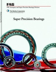
PRECISIONTECHNOLOGYINSIDESUPER PREC
- Page 3 and 4:
CONTENTSPrecision Technology Inside
- Page 5 and 6:
PRECISION TECHNOLOGY INSIDEOptimum
- Page 7 and 8:
PRECISION TECHNOLOGY INSIDEProduct
- Page 9 and 10:
SPINDLE BEARINGSFAG spindle bearing
- Page 11 and 12:
SPINDLE BEARINGSDIRECT LUBE Bearing
- Page 13 and 14:
SPINDLE BEARINGSB NS NS BB Nr ar br
- Page 15 and 16:
SPINDLE BEARINGSB NS NS BB Nr ar br
- Page 17 and 18:
SPINDLE BEARINGSB NS NS BB Nr ar br
- Page 19 and 20:
SPINDLE BEARINGSB NS NS BB Nr ar br
- Page 21 and 22:
SPINDLE BEARINGSB NS NS BB Nr ar br
- Page 23 and 24:
SPINDLE BEARINGSB NS NS BB Nr ar br
- Page 25 and 26:
SPINDLE BEARINGSB NS NS BB Nr ar br
- Page 27 and 28:
SPINDLE BEARINGSB NS NS BB Nr ar br
- Page 29 and 30:
SPINDLE BEARINGSB NS NS BB Nr ar br
- Page 31 and 32:
SPINDLE BEARINGSB NS NS BB Nr ar br
- Page 33 and 34:
SPINDLE BEARINGSB NS NS BB Nr ar br
- Page 35 and 36:
SPINDLE BEARINGSB NS NS BB Nr ar br
- Page 37 and 38:
SPINDLE BEARINGSB NS NS BB Nr ar br
- Page 39 and 40:
SPINDLE BEARINGSB NS NS BB Nr ar br
- Page 41 and 42:
SPINDLE BEARINGSB NS NS BB Nr ar br
- Page 43 and 44:
SPINDLE BEARINGSB NS NS BB Nr ar br
- Page 45 and 46:
SPINDLE BEARINGSB NS NS BB Nr ar br
- Page 47 and 48:
SPINDLE BEARINGSB NS NS BB Nr ar br
- Page 49 and 50:
SPINDLE BEARINGSB NS NS BB Nr ar br
- Page 51 and 52:
SPINDLE BEARINGSB NS NS BB Nr ar br
- Page 53 and 54:
SPINDLE BEARINGSB NS NS BB Nr ar br
- Page 55 and 56:
SPINDLE BEARINGSB NS NS BB Nr ar br
- Page 57 and 58:
SPINDLE BEARINGSB NS NS BB Nr ar br
- Page 59 and 60:
SPINDLE BEARINGSB NS NS BB Nr ar br
- Page 61 and 62:
SPINDLE BEARINGSB NS NS BB Nr ar br
- Page 63 and 64:
SPINDLE BEARINGSB NS NS BB Nr ar br
- Page 65 and 66:
SPINDLE BEARINGSB NS NS BB Nr ar br
- Page 67 and 68:
SPINDLE BEARINGSB NS NS BB Nr ar br
- Page 69 and 70:
SPINDLE BEARINGSB NS NS BB Nr ar br
- Page 71 and 72:
SPINDLE BEARINGSB NS NS BB Nr ar br
- Page 73 and 74:
SPINDLE BEARINGSB NS NS BB Nr ar br
- Page 75 and 76:
SPINDLE BEARINGSB NS NS BB Nr ar br
- Page 77 and 78:
SPINDLE BEARINGSB NS NS BB Nr ar br
- Page 79 and 80:
FLOATING DISPLACEMENT BEARINGSThe f
- Page 81 and 82:
FLOATING DISPLACEMENT BEARINGSr ar
- Page 83 and 84: FLOATING DISPLACEMENT BEARINGSr ar
- Page 85 and 86: SUPER PRECISION CYLINDRICAL ROLLER
- Page 87 and 88: SUPER PRECISION CYLINDRICAL ROLLER
- Page 89 and 90: SUPER PRECISION CYLINDRICAL ROLLER
- Page 91 and 92: SUPER PRECISION CYLINDRICAL ROLLER
- Page 93 and 94: SUPER PRECISION CYLINDRICAL ROLLER
- Page 95 and 96: SUPER PRECISION CYLINDRICAL ROLLER
- Page 97 and 98: SUPER PRECISION CYLINDRICAL ROLLER
- Page 99 and 100: SUPER PRECISION CYLINDRICAL ROLLER
- Page 101 and 102: SUPER PRECISION CYLINDRICAL ROLLER
- Page 103 and 104: DOUBLE DIRECTION ANGULAR CONTACT TH
- Page 105 and 106: DOUBLE DIRECTION ANGULAR CONTACT TH
- Page 107 and 108: DOUBLE DIRECTION ANGULAR CONTACT TH
- Page 109 and 110: DOUBLE DIRECTION ANGULAR CONTACT TH
- Page 111 and 112: DOUBLE DIRECTION ANGULAR CONTACT TH
- Page 113 and 114: ANGULAR CONTACT THRUST BALL BEARING
- Page 115 and 116: ANGULAR CONTACT THRUST BALL BEARING
- Page 117 and 118: ANGULAR CONTACT THRUST BALL BEARING
- Page 119 and 120: ANGULAR CONTACT THRUST BALL BEARING
- Page 121 and 122: ANGULAR CONTACT THRUST BALL BEARING
- Page 123 and 124: ANGULAR CONTACT THRUST BALL BEARING
- Page 125 and 126: ANGULAR CONTACT THRUST BALL BEARING
- Page 127 and 128: ANGULAR CONTACT THRUST BALL BEARING
- Page 129 and 130: AXIAL-RADIAL CYLINDRICAL ROLLER BEA
- Page 131 and 132: AXIAL-RADIAL CYLINDRICAL ROLLER BEA
- Page 133: AXIAL-RADIAL CYLINDRICAL ROLLER BEA
- Page 137 and 138: LIFE CALCULATION FOR SUPER PRECISIO
- Page 139 and 140: LIFE CALCULATION FOR SUPER PRECISIO
- Page 141 and 142: LIFE CALCULATION FOR SUPER PRECISIO
- Page 143 and 144: LIFE CALCULATION FOR SUPER PRECISIO
- Page 145 and 146: LUBRICATIONGrease LubricationL210 i
- Page 147 and 148: LUBRICATIONGrease LubricationGrease
- Page 149 and 150: LUBRICATIONOil LubricationMinimal O
- Page 151 and 152: TOLERANCES FOR SUPER PRECISION BEAR
- Page 153 and 154: TOLERANCES FOR SUPER PRECISION BEAR
- Page 155 and 156: TOLERANCES FOR SUPER PRECISION BEAR
- Page 157 and 158: TOLERANCES FOR SUPER PRECISION BEAR
- Page 159 and 160: TOLERANCES FOR SUPER PRECISION BEAR
- Page 161 and 162: TOLERANCES FOR SUPER PRECISION BEAR
- Page 163 and 164: MACHINING TOLERANCES FOR MATING PAR
- Page 165 and 166: MACHINING TOLERANCES FOR MATING PAR
- Page 167 and 168: MACHINING TOLERANCES FOR MATING PAR
- Page 169 and 170: MACHINING TOLERANCES FOR MATING PAR
- Page 171 and 172: MACHINING TOLERANCES FOR MATING PAR
- Page 173 and 174: SPEED-DEPENDENT FITSSpeed-Dependent
- Page 175 and 176: SPEEDSSpeedsThe speeds attainable b
- Page 177 and 178: DEFLECTION AND RIGIDITYDeflection a
- Page 179 and 180: HANDLING OF SUPER PRECISION BEARING
- Page 181 and 182: HANDLING OF SUPER PRECISION BEARING
- Page 183 and 184: SPICAS 2000SPICAS 2000 - the PC Pro
- Page 185 and 186:
SPINDLE BEARINGSCalendar weekof pro
- Page 187 and 188:
BEARING CODE SPINDLE BEARINGSB 70 0
- Page 189 and 190:
FAG · 188
- Page 191 and 192:
BEARING CODEFLOATING DISPLACEMENT B
- Page 193 and 194:
FAG · 192
- Page 195 and 196:
BEARING CODESUPER PRECISION CYLINDR
- Page 197 and 198:
FAG · 196
- Page 199 and 200:
BEARING CODEDOUBLE DIRECTION ANGULA
- Page 201 and 202:
FAG · 200
- Page 203 and 204:
BEARING CODEANGULAR CONTACT THRUST
- Page 205 and 206:
FAG · 204
- Page 207 and 208:
BEARING CODEAXIAL-RADIAL CYLINDRICA
- Page 209 and 210:
NOTESFAG · 208
- Page 211 and 212:
Every care has been taken to ensure