Design of Deep Underground stations in soft soil ... - Royal Haskoning
Design of Deep Underground stations in soft soil ... - Royal Haskoning
Design of Deep Underground stations in soft soil ... - Royal Haskoning

You also want an ePaper? Increase the reach of your titles
YUMPU automatically turns print PDFs into web optimized ePapers that Google loves.
FE MODEL VALIDATION<br />
The ma<strong>in</strong> objective <strong>of</strong> the FE calculations is to create a frame <strong>of</strong> reference for the expected deformations. For<br />
this reason a large amount <strong>of</strong> sensitivity calculations were made after which a set <strong>of</strong> new calculations was<br />
created. In this new set <strong>of</strong> calculations the <strong>soil</strong> parameters (lower, average and upper limit value) were varied<br />
such that special features like maximum horizontal bend<strong>in</strong>g <strong>of</strong> diaphragm wall could be calculated.<br />
The 3D FE model is validated with the results <strong>of</strong> a special test project. This test project was conducted to<br />
ga<strong>in</strong> more <strong>in</strong>sight <strong>in</strong> the deformations that occur dur<strong>in</strong>g <strong>in</strong>stallation <strong>of</strong> a diaphragm wall <strong>in</strong> Amsterdam <strong>soil</strong><br />
conditions.<br />
After validation <strong>of</strong> the 3D FE model the total deformations, <strong>in</strong>stallation <strong>of</strong> diaphragm wall (3D FE model)+<br />
excavation <strong>of</strong> build<strong>in</strong>g pit (2D FE model) are calculated.<br />
Diaphragm wall test<br />
The ma<strong>in</strong> objectives for the full-scale test on a construction site <strong>in</strong> Amsterdam are:<br />
• Expand<strong>in</strong>g the knowledge on this subject, so that design if necessary can be made <strong>in</strong> advance.<br />
• Validation <strong>of</strong> 3D- FE model based on the test results.<br />
• Ga<strong>in</strong>ed <strong>in</strong>sight <strong>in</strong> the specific execution aspects <strong>of</strong> diaphragm wall <strong>in</strong>stallation <strong>in</strong> Amsterdam <strong>soil</strong>.<br />
The test project <strong>of</strong> the diaphragm wall <strong>in</strong>stallation consists <strong>of</strong> three parts:<br />
1. Prediction <strong>of</strong> the impact with a 3D FE model<br />
2. Full scale test at a construction site <strong>in</strong> Amsterdam<br />
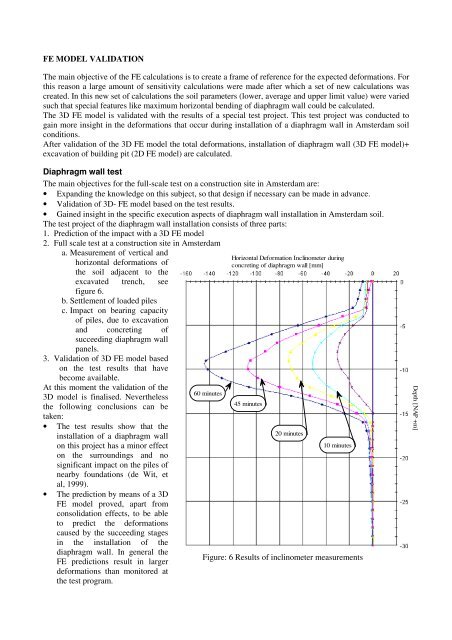
a. Measurement <strong>of</strong> vertical and<br />
horizontal deformations <strong>of</strong><br />
the <strong>soil</strong> adjacent to the<br />
excavated trench, see<br />
figure 6.<br />
b. Settlement <strong>of</strong> loaded piles<br />
c. Impact on bear<strong>in</strong>g capacity<br />
<strong>of</strong> piles, due to excavation<br />
and concret<strong>in</strong>g <strong>of</strong><br />
succeed<strong>in</strong>g diaphragm wall<br />
panels.<br />
3. Validation <strong>of</strong> 3D FE model based<br />
on the test results that have<br />
become available.<br />
At this moment the validation <strong>of</strong> the<br />
3D model is f<strong>in</strong>alised. Nevertheless<br />
the follow<strong>in</strong>g conclusions can be<br />
taken:<br />
• The test results show that the<br />
<strong>in</strong>stallation <strong>of</strong> a diaphragm wall<br />
on this project has a m<strong>in</strong>or effect<br />
on the surround<strong>in</strong>gs and no<br />
significant impact on the piles <strong>of</strong><br />
nearby foundations (de Wit, et<br />
al, 1999).<br />
• The prediction by means <strong>of</strong> a 3D<br />
FE model proved, apart from<br />
consolidation effects, to be able<br />
to predict the deformations<br />
caused by the succeed<strong>in</strong>g stages<br />
<strong>in</strong> the <strong>in</strong>stallation <strong>of</strong> the<br />
diaphragm wall. In general the<br />
FE predictions result <strong>in</strong> larger<br />
deformations than monitored at<br />
the test program.<br />
60 m<strong>in</strong>utes<br />
Horizontal Deformation Incl<strong>in</strong>ometer dur<strong>in</strong>g<br />
concret<strong>in</strong>g <strong>of</strong> diaphragm wall [mm]<br />
45 m<strong>in</strong>utes<br />
20 m<strong>in</strong>utes<br />
10 m<strong>in</strong>utes<br />
Figure: 6 Results <strong>of</strong> <strong>in</strong>cl<strong>in</strong>ometer measurements<br />
Depth [NAP +m]