Success story continues: The R&S®DDF04E direction finder ...
Success story continues: The R&S®DDF04E direction finder ...
Success story continues: The R&S®DDF04E direction finder ...

Create successful ePaper yourself
Turn your PDF publications into a flip-book with our unique Google optimized e-Paper software.
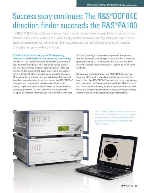
<strong>Success</strong> <strong>story</strong> <strong>continues</strong>: <strong>The</strong> R&S®DDF04E<strong>direction</strong> <strong>finder</strong> succeeds the R&S®PA100<strong>The</strong> R&S®PA100 family of Doppler <strong>direction</strong> <strong>finder</strong>s has for decades been in use in large numbers in air andmaritime traffic control worldwide. It is now being gradually phased out and replaced by the R&S®DDF 04Edigital <strong>direction</strong> <strong>finder</strong> for traffic control. This new generation can take bearings on up to 32 frequencychannels using only one <strong>direction</strong> <strong>finder</strong>.RADIOMONITORING / RADIOLOCATION | Direction <strong>finder</strong>sOne <strong>direction</strong> <strong>finder</strong> for up to 32 frequencychannels – with high DF accuracy and sensitivity<strong>The</strong> R&S®PA100 Doppler <strong>direction</strong> <strong>finder</strong> family, deployed inlarge numbers worldwide, now has a high-speed successor:the R&S®DDF04E digital <strong>direction</strong> <strong>finder</strong> for traffic control(FIG 1). Conventional DF systems for traffic control consistof multiple DF plug-in modules connected to the sameDF antenna. Each of these plug-in modules is a full-featuredfixed-frequency <strong>direction</strong> <strong>finder</strong>. In contrast, the R&S®DDF04Estate-of-the-art digital wideband <strong>direction</strong> <strong>finder</strong> is fastenough to process a multitude of frequency channels simultaneously:Between 100 MHz and 450 MHz, it can monitorup to 32 channels (optionally) at the same time, with highDF quality and high measurement speed on all channels.This allows parallel monitoring of typical aviation distress frequenciessuch as 121.5 MHz and 243 MHz, and any activityon these frequencies immediately triggers an alarm to thecontroller.<strong>The</strong> receiver characteristics of the R&S®DDF04E, such aslarge-signal immunity, selectivity and sensitivity, are excellent.In fact, the R&S®DDF04E exceeds the recommendationsof the International Telecommunication Union (ITU) for <strong>direction</strong><strong>finder</strong>s and monitoring receivers in many cases and alsomeets the stringent requirements of Deutsche FlugsicherungGmbH (German air navigation services organisation).FIG 1 <strong>The</strong> R&S®DDF04E digital <strong>direction</strong> <strong>finder</strong> fortraffic control. Standard PCs can be used to controlthe <strong>direction</strong> <strong>finder</strong> and display the results, whichgreatly reduces the costs per workstation andincreases flexibility.NEWS 202/10 39
RADIOMONITORING / RADIOLOCATION | Direction <strong>finder</strong>sAnother major advantage of the R&S®DDF04E is that it isideally suited to handle forthcoming ATC requirements. Forexample, the 8.33 kHz channel spacing for aeronautical radiois already integrated. In addition, the frequencies of the channelsbeing monitored can be changed via mouse click.<strong>The</strong> R&S®DDF04E uses the correlative interferometerDF method. This method is based on measuring the phasedifferences between the antenna elements of a circular-arrayDF antenna, permitting the use of wide-aperture antennas.<strong>The</strong> higher level of DF accuracy and immunity to reflections isparticularly evident when compared to conventional Watson-Watt DF methods, which are still used in maritime traffic controlapplications.Example of application in air traffic controlR&S®DDF04E at Brumowski air base in Austria(ICAO code: LOXT)<strong>The</strong> Brumowski air base of the Austrian Air Force, which is underthe control of the Austrian Federal Ministry of Defense and Sports(BMLVS), is located west of Vienna, in Langenlebarn near Tulln.<strong>The</strong> air base houses the maintenance hangar 1, the air supportwing, a school for air and anti-aircraft defense and the federalschool for aeronautical engineering.<strong>The</strong> R&S®GB4000T control unit is used for the controller settingsand as an additional display if the radar fails, or to monitoran additional frequency of neighboring civil airports or airfields.<strong>The</strong> tower workstation is equipped with an R&S®EB110 miniportreceiver and the R&S®GB4000V audio unit.<strong>The</strong> R&S®PA008 <strong>direction</strong> <strong>finder</strong>, installed in the 1980s, operatedreliably throughout the many years and contributed significantlyto overall air traffic safety – until aging of the system and its limitationto only four DF channels prompted the BMLVS to purchasea replacement.<strong>The</strong> R&S®ADD050SR DF antenna was mounted on a steel mastfive meters high, together with an LED obstruction light (FIG 2).This mast height is a compromise between contradictory technicalrequirements: To avoid nulls in the vertical antenna pattern resultingfrom ground reflections, the mast height should be kept aslow as possible; for increasing the range, however, a higher mastwould be necessary. Except for reliable grounding of the antenna,no other measures are required because the antenna elementsand the DF receiver are already equipped with integrated lightningprotection. An insulated and fully air-conditioned outdoor cabinetat the mast base houses the DF equipment and the DF server.Suitable overvoltage arresters for the power supply and data lineswere installed at the housing inlet.<strong>The</strong> data connection to the control units for the two radar workstationsand for the tower workstation runs via a four-wire VDSLdata modem (copper cables). A PC in the equipment room for onlinemonitoring allows direct access to the server PC and to theworkstations. Two compact R&S®GB4000T control units in theradar room and one in the tower are specially designed for use inair traffic control consoles. <strong>The</strong>y are touch input devices (TID) andare also used, for example, to operate R&S®Series4200 airborneradios via voice over IP.FIG 2 <strong>The</strong> R&S®DDF04E <strong>direction</strong> <strong>finder</strong> at Brumowski air base. Aninsulated and fully air-conditioned outdoor cabinet at the mast basehouses the DF equipment and the DF server.Photo: Author40
RADIOMONITORING / RADIOLOCATION | Direction <strong>finder</strong>sExample of application in air traffic controlLANRS-232-CAdministrationRadar display 1Radar display 2Radar display 3Ground transmitter suppressionConverterTTL/OC to LANAirborne radiosWorkstations, e.g. R&S®GB 4000T¸DDF 04EDF server•••FIG 3 Typical air traffic control system featuring the R&S®DDF04E digital <strong>direction</strong> <strong>finder</strong> for traffic control.Wide frequency range with only one antenna<strong>The</strong> R&S®ADD050SR wide-aperture DF antenna covers theentire frequency range of the R&S®DDF04E, from 100 MHz to450 MHz. With a diameter of 3 m and a total of nine antennaelements, it offers high DF accuracy and sensitivity plus outstandingimmunity to reflections. For mobile and semi-mobileuse, the R&S®ADD153SR compact antenna with a diameterof 1.1 m is available.Built-in selftest (BITE) capabilities are indispensable, particularlyin safety-relevant applications such as air and maritimetraffic control. <strong>The</strong> R&S®DDF04E continuously checks themeasured values of more than 170 test points during operationand compares the results with the nominal values. Avalue outside the nominal value range automatically triggersan error message.Robert MatousekSimple networking and controlStandard PCs can be used to control the <strong>direction</strong> <strong>finder</strong> anddisplay the results. This greatly reduces the costs per workstationand increases flexibility. For example, TIDs such asthe R&S®GB4000T and, in mobile systems, laptops can beutilized. <strong>The</strong> <strong>direction</strong> <strong>finder</strong> and the PCs (control PC andDF server) can be networked via LAN (TCP/IP); standard productscan also be used for this purpose (FIG 3).Customer-specific traffic management systems and/or radardisplays can likewise be linked via LAN. As an alternative,RS-232-C interfaces are available. <strong>The</strong> data format matchesthat of the R&S®PA100 – which can therefore be replacedwith an R&S®DDF04E with no additional effort. Control informationfor ground transmitter suppression is first convertedto the TCP/IP format by means of one or more converters.<strong>The</strong> data can then be queried and utilized by the R&S®DDF04Evia the network.Key features of the R&S®DDF04E at a glance❙❙Parallel <strong>direction</strong> finding on up to 32 channels(optional) with the same high level of DF quality andsensitivity on all channels❙❙Seamless coverage of a wide frequency range from100 MHz to 450 MHz with only one DF antenna❙❙Future-ready through simple change of the receivefrequency and number of channels via the controlsoftware, as well as through the forthcoming 8.33 kHzchannel spacing that is already integrated❙❙Standard PCs, monitors and network technology forcontrol and display❙❙Flexible networking of <strong>direction</strong> <strong>finder</strong>, data server anddisplay units via Ethernet❙❙Output of results on radar displays and in traffic managementsystems via an RS-232-C or TCP/IP interfaceNEWS 202/10 41