Adaptive PI Controller for a Nonlinear System - International ...
Adaptive PI Controller for a Nonlinear System - International ...
Adaptive PI Controller for a Nonlinear System - International ...

Create successful ePaper yourself
Turn your PDF publications into a flip-book with our unique Google optimized e-Paper software.
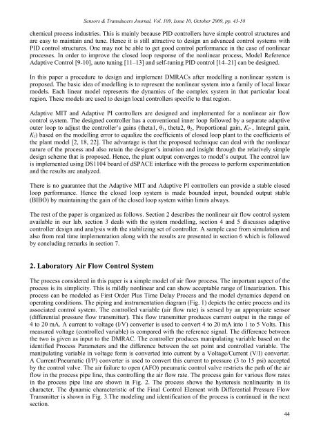
Sensors & Transducers Journal, Vol. 109, Issue 10, October 2009, pp. 43-58chemical process industries. This is mainly because <strong>PI</strong>D controllers have simple control structures andare easy to maintain and tune. Hence it is still attractive to design an advanced control systems with<strong>PI</strong>D control structures. One may not be able to get good control per<strong>for</strong>mance in the case of nonlinearprocesses. In order to improve the closed loop response of the nonlinear process, Model Reference<strong>Adaptive</strong> Control [9-10], auto tuning [11–13] and self-tuning <strong>PI</strong>D control [14–21] can be designed.In this paper a procedure to design and implement DMRACs after modelling a nonlinear system isproposed. The basic idea of modelling is to represent the nonlinear system into a family of local linearmodels. Each linear model represents the dynamics of the complex system in that particular localregion. These models are used to design local controllers specific to that region.<strong>Adaptive</strong> MIT and <strong>Adaptive</strong> <strong>PI</strong> controllers are designed and implemented <strong>for</strong> a nonlinear air flowcontrol system. The designed controller has a conventional inner loop followed by a separate adaptiveouter loop to adjust the controller’s gains (theta1, θ 1 , theta2, θ 2 , Proportional gain, K P , Integral gain,K I ) based on the modelling error to equalize the coefficients of closed loop plant to the coefficients ofthe plant model [2, 18, 22]. The advantage is that the proposed technique can deal with the nonlinearnature of the process and also retain the designer’s intuition and insight through the relatively simpledesign scheme that is proposed. Hence, the plant output converges to model’s output. The control lawis implemented using DS1104 board of dSPACE interface with the process to per<strong>for</strong>m experimentationand the results are analyzed.There is no guarantee that the <strong>Adaptive</strong> MIT and <strong>Adaptive</strong> <strong>PI</strong> controllers can provide a stable closedloop per<strong>for</strong>mance. Hence the closed loop system is made bounded input, bounded output stable(BIBO) by maintaining the gain of the closed loop system within limits always.The rest of the paper is organized as follows. Section 2 describes the nonlinear air flow control systemavailable in our lab, section 3 deals with the system modelling, section 4 and 5 discusses adaptivecontroller design and analysis with the stabilizing set of controller. A sample case from simulation andalso from real time implementation along with the results are presented in section 6 which is followedby concluding remarks in section 7.2. Laboratory Air Flow Control <strong>System</strong>The process considered in this paper is a simple model of air flow process. The important aspect of theprocess is its simplicity. This is mildly nonlinear and can show acceptable range of linearization. Thisprocess can be modeled as First Order Plus Time Delay Process and the model dynamics depend onoperating conditions. The piping and instrumentation diagram (Fig. 1) depicts the entire process and itsassociated control system. The controlled variable (air flow rate) is sensed by an appropriate sensor(differential pressure flow transmitter). This flow transmitter produces current output in the range of4 to 20 mA. A current to voltage (I/V) converter is used to convert 4 to 20 mA into 1 to 5 Volts. Thismeasured voltage (controlled variable) is compared with the reference signal. The difference betweenthe two is given as input to the DMRAC. The controller produces manipulating variable based on theidentified Process Parameters and the difference between the set point and controlled variable. Themanipulating variable in voltage <strong>for</strong>m is converted into current by a Voltage/Current (V/I) converter.A Current/Pneumatic (I/P) converter is used to convert this current to pressure (3 to 15 psi) acceptedby the control valve. The air failure to open (AFO) pneumatic control valve restricts the path of the airflow in the process pipe line, thus controlling the air flow rate. The process gain <strong>for</strong> various flow ratesin the process pipe line are shown in Fig. 2. The process shows the hysteresis nonlinearity in itscharacter. The dynamic characteristic of the Final Control Element with Differential Pressure FlowTransmitter is shown in Fig. 3.The modeling and identification of the process is continued in the nextsection.44