Product Manual - Digisol.com
Product Manual - Digisol.com
Product Manual - Digisol.com

You also want an ePaper? Increase the reach of your titles
YUMPU automatically turns print PDFs into web optimized ePapers that Google loves.
TMDG-GS4528SGigabit Ethernet Managed Layer 2 SwitchUser <strong>Manual</strong>V1.02010-11-16As our product undergoes continuous development the specifications are subject to change without prior notice
TMDG-GS4528S User <strong>Manual</strong>COPYRIGHTCopyright © 2010 by SNSL. All rights reserved. No part of this publication may be reproduced,transmitted, transcribed, stored in a retrieval system, or translated into any languageor <strong>com</strong>puter language, in any form or by any means, electronic, mechanical,magnetic, optical, chemical, manual or otherwise, without the prior written permission ofSNSL.SNSL makes no representations or warranties, either expressed or implied, with respect tothe contents hereof and specifically disclaims any warranties, merchantability or fitness forany particular purpose. Any software described in this manual is sold or licensed “as is”.Should the programs prove defective following their purchase, the buyer (and not SNSL, itsdistributor, or its dealer) assumes the entire cost of all necessary servicing, repair, and anyincidental or consequential damages resulting from any defect in the software. Further,SNSL reserves the right to revise this publication and to make changes from time to time inthe contents thereof without obligation to notify any person of such revision or changes.SNSL an abbreviation of Smartlink Network Systems Ltd.
USER MANUALDG-GS4528S GIGABIT ETHERNET MANAGED LAYER 2 SWITCHLayer 2 Switchwith 24 10/100/1000BASE-T (RJ-45) Ports,and 4 Gigabit Combination Ports (RJ-45/SFP)DG-GS4528SE112010-CS-R01149100000109A
ABOUT THIS GUIDEPURPOSEThis guide gives specific information on how to operate and use themanagement functions of the switch.AUDIENCEThe guide is intended for use by network administrators who areresponsible for operating and maintaining network equipment;consequently, it assumes a basic working knowledge of general switchfunctions, the Internet Protocol (IP), and Simple Network ManagementProtocol (SNMP).CONVENTIONSThe following conventions are used throughout this guide to showinformation:NOTE: Emphasizes important information or calls your attention to relatedfeatures or instructions.CAUTION: Alerts you to a potential hazard that could cause loss of data, ordamage the system or equipment.WARNING: Alerts you to a potential hazard that could cause personal injury.RELATED PUBLICATIONSThe following publication details the hardware features of the switch,including the physical and performance-related characteristics, and how toinstall the switch:The Installation GuideAlso, as part of the switch’s software, there is an online web-based helpthat describes all management related features.REVISION HISTORYThis section summarizes the changes in each revision of this guide.NOVEMBER 2010 REVISIONThis is the first version of this guide. This guide is valid for software releasev1.1.0.3.– 5 –
ABOUT THIS GUIDE– 6 –
CONTENTSABOUT THIS GUIDE 5CONTENTS 7FIGURES 23TABLES 27SECTION I GETTING STARTED 291 INTRODUCTION 31Key Features 31Description of Software Features 32Configuration Backup and Restore 32Authentication 32Access Control Lists 33Port Configuration 33Rate Limiting 33Port Mirroring 33Port Trunking 33Storm Control 33Static Addresses 33IEEE 802.1D Bridge 34Store-and-Forward Switching 34Spanning Tree Algorithm 34Virtual LANs 35Traffic Prioritization 35Quality of Service 35Multicast Filtering 35System Defaults 362 INITIAL SWITCH CONFIGURATION 39Connecting to the Switch 39– 7 –
CONTENTSConfiguration Options 39Required Connections 40Remote Connections 41Logging into the CLI 41Basic Configuration 42Setting Passwords 42Setting an IP Address 42<strong>Manual</strong> Configuration 43Dynamic Configuration 45Enabling SNMP Management Access 46Community Strings (for SNMP version 1 and 2c clients) 46Trap Receivers 47Configuring Access for SNMP Version 3 Clients 48Managing System Files 49Saving or Restoring Configuration Settings 49SECTION II WEB CONFIGURATION 513 USING THE WEB INTERFACE 53Connecting to the Web Interface 53Navigating the Web Browser Interface 54Home Page 54Configuration Options 54Panel Display 55Main Menu 554 CONFIGURING THE SWITCH 61Configuring System Information 61Setting an IP Address 62Setting an IPv4 Address 62Setting an IPv6 Address 64Configuring NTP Service 66Configuring Port Connections 67Configuring Security 70Configuring User Accounts 70Configuring User Privilege Levels 72Configuring The Authentication Method For Management Access 74– 8 –
CONTENTSConfiguring SSH 77Configuring HTTPS 78Filtering IP Addresses for Management Access 79Using Simple Network Management Protocol 81Configuring SNMP System and Trap Settings 82Setting SNMPv3 Community Access Strings 86Configuring SNMPv3 Users 87Configuring SNMPv3 Groups 88Configuring SNMPv3 Views 90Configuring SNMPv3 Group Access Rights 91Configuring Port Limit Controls 92Configuring Authentication Through Network Access Servers 94Filtering Traffic with Access Control Lists 105Assigning ACL Policies and Responses 105Configuring Rate Limiters 107Configuring Access Control Lists 108Configuring DHCP Snooping 115Configuring DHCP Relay and Option 82 Information 118Configuring IP Source Guard 119Configuring Global and Port Settings for IP Source Guard 119Configuring Static Bindings for IP Source Guard 121Configuring ARP Inspection 123Configuring Global and Port Settings for ARP Inspection 124Configuring Static Bindings for ARP Inspection 125Specifying Authentication Servers 126Creating Trunk Groups 128Configuring Static Trunks 129Configuring LACP 132Configuring the Spanning Tree Algorithm 135Configuring Global Settings for STA 137Configuring Multiple Spanning Trees 140Configuring Spanning Tree Bridge Priorities 142ConfiguringSTP/RSTP/CIST Interfaces 143Configuring MIST Interfaces 147IGMP Snooping 149Configuring Global and Port-Related Settings for IGMP Snooping 149– 9 –
CONTENTSConfiguring VLAN Settings for IGMP Snooping and Query 152Configuring IGMP Filtering 153MLD Snooping 154Configuring Global and Port-Related Settings for MLD Snooping 155Configuring VLAN Settings for MLD Snooping and Query 158Configuring MLD Filtering 159Multicast VLAN Registration 160Link Layer Discovery Protocol 163Configuring LLDP Timing and TLVs 163Configuring LLDP-MED TLVs 166Configuring the MAC Address Table 172IEEE 802.1Q VLANs 174Assigning Ports to VLANs 175Configuring VLAN Attributes for Port Members 176Configuring Private VLANs 178Using Port Isolation 180Managing VoIP Traffic 181Configuring VoIP Traffic 181Configuring Telephony OUI 183Quality of Service 185Configuring Port-Level Queue Settings 185Configuring DSCP Remarking 187Configuring QoS Control Lists 189Configuring Rate Limiting 191Configuring Storm Control 193Configuring Port Mirroring 194Configuring UPnP 1955 MONITORING THE SWITCH 197Displaying Basic Information About the System 197Displaying System Information 197Displaying CPU Utilization 198Displaying Log Messages 199Displaying Log Details 200Displaying Information About Ports 201Displaying Port Status On the Front Panel 201Displaying an Overview of Port Statistics 201– 10 –
CONTENTSDisplaying QoS Statistics 202Displaying Detailed Port Statistics 203Displaying Information About Security Settings 205Displaying Access Management Statistics 205Displaying Information About Switch Settings for Port Security 206Displaying Information About Learned MAC Addresses 208Displaying Port Status for Authentication Services 209Displaying Port Statistics for 802.1X or Remote Authentication Service210Displaying ACL Status 214Displaying Statistics for DHCP Snooping 215Displaying DHCP Relay Statistics 217Displaying MAC Address Bindings for ARP Packets 219Displaying Entries in the IP Source Guard Table 219Displaying Information on Authentication Servers 220Displaying a List of Authentication Servers 220Displaying Statistics for Configured Authentication Servers 221Displaying Information on LACP 225Displaying an Overview of LACP Groups 225Displaying LACP Port Status 226Displaying LACP Port Statistics 227Displaying Information on the Spanning Tree 228Displaying Bridge Status for STA 228Displaying Port Status for STA 230Displaying Port Statistics for STA 231Showing IGMP Snooping Information 232Showing MLD Snooping Information 234Displaying MVR Information 235Displaying LLDP Information 237Displaying LLDP Neighbor Information 237Displaying LLDP-MED Neighbor Information 238Displaying LLDP Port Statistics 241Displaying the MAC Address Table 242Displaying Information About VLANs 243VLAN Membership 243VLAN Port Status 244– 11 –
CONTENTS6 PERFORMING BASIC DIAGNOSTICS 247Pinging an IPv4 or IPv6 Address 247Running Cable Diagnostics 2487 PERFORMING SYSTEM MAINTENANCE 251Restarting the Switch 251Restoring Factory Defaults 252Upgrading Firmware 252Managing Configuration Files 253Saving Configuration Settings 253Restoring Configuration Settings 254SECTION III COMMAND LINE INTERFACE 2558 USING THE COMMAND LINE INTERFACE 257Accessing the CLI 257Console Connection 257Telnet Connection 258Entering Commands 259Keywords and Arguments 259Minimum Abbreviation 259Getting Help on Commands 259Showing Commands 260Partial Keyword Lookup 261Using Command History 261Command Line Processing 262CLI Command Groups 2639 SYSTEM COMMANDS 265system configuration 265system name 266system contact 266system location 267system timezone 267system reboot 268system restore default 268system load 268– 12 –
CONTENTSsystem log 26910 IP COMMANDS 271ip configuration 271ip dhcp 272ip setup 273ip ping 275ip dns 276ip dns_proxy 276ip ipv6 autoconfig 277ip ipv6 setup 278ip ipv6 ping6 279ip ntp configuration 280ip ntp mode 280ip ntp server add 281ip ntp server ipv6 add 281ip ntp server delete 28211 PORT COMMANDS 283port configuration 283port mode 285port flow control 285port state 286port maxframe 287port power 287port excessive 288port statistics 289port veriphy 29012 MAC COMMANDS 293mac configuration 293mac add 294mac delete 294mac lookup 295mac agetime 295mac learning 295mac dump 296mac statistics 297– 13 –
CONTENTSmac flush 29713 VLAN COMMANDS 299vlan configuration 299vlan aware 300vlan pvid 301vlan frametype 301vlan ingressfilter 302vlan stag 302vlan add 303vlan delete 303vlan lookup 304vlan status 30414 PVLAN COMMANDS 307pvlan configuration 307pvlan add 308pvlan delete 308pvlan lookup 309pvlan isolate 30915 SECURITY COMMANDS 311User Configuration 312security switch users configuration 312security switch users add 312security switch users delete 313Privilege Level Configuration 313security switch privilege level configuration 313security switch privilege level group 314security switch privilege level current 316Protocol Authentication Commands 316security switch auth configuration 316security switch auth method 317SSH Commands 318security switch ssh configuration 318security switch ssh mode 318HTTPS Commands 319security switch https configuration 320– 14 –
CONTENTSsecurity switch https mode 320security switch https redirect 321Management Access Commands 322security switch access configuration 322security switch access mode 323security switch access add 323security switch access ipv6 add 324security switch access delete 325security switch access lookup 325security switch access clear 325security switch access statistics 326SNMP Commands 326security switch snmp configuration 328security switch snmp mode 329security switch snmp version 330security switch snmp read <strong>com</strong>munity 330security switch snmp write <strong>com</strong>munity 331security switch snmp trap mode 331security switch snmp trap version 332security switch snmp trap <strong>com</strong>munity 332security switch snmp trap destination 332security switch snmp trap ipv6 destination 333security switch snmp trap authentication failure 333security switch snmp trap link-up 334security switch snmp trap inform mode 334security switch snmp trap inform timeout 335security switch snmp trap inform retry times 335security switch snmp trap probe security engine id 336security switch snmp trap security engine id 336security switch snmp trap security name 337security switch snmp engine id 337security switch snmp <strong>com</strong>munity add 338security switch snmp <strong>com</strong>munity delete 339security switch snmp <strong>com</strong>munity lookup 339security switch snmp user add 340security switch snmp user delete 341– 15 –
CONTENTSsecurity switch snmp user changekey 341security switch snmp user lookup 342security switch snmp group add 342security switch snmp group delete 343security switch snmp group lookup 343security switch snmp view add 344security switch snmp view delete 345security switch snmp view lookup 345security switch snmp access add 346security switch snmp access delete 346security switch snmp access lookup 347Port Security Status 347security network psec switch 348security network psec port 348Port Security Limit Control 349security network limit configuration 350security network limit mode 350security network limit aging 351security network limit agetime 351security network limit port 352security network limit limit 352security network limit action 353security network limit reopen 354Network Access Server Commands 354security network nas configuration 355security network nas mode 356security network nas state 356security network nas reauthentication 359security network nas reauthperiod 359security network nas eapoltimeout 360security network nas agetime 360security network nas holdtime 361security network nas radius_qos 361security network nas radius_vlan 362security network nas guest_vlan 364security network nas authenticate 365– 16 –
CONTENTSsecurity network nas statistics 366ACL Commands 367security network acl configuration 367security network acl action 368security network acl policy 369security network acl rate 369security network acl add 370security network acl delete 373security network acl lookup 373security network acl clear 374security network acl status 374DHCP Relay Commands 375security network dhcp relay configuration 375security network dhcp relay mode 376security network dhcp relay server 376security network dhcp relay information mode 377security network dhcp relay information policy 378security network dhcp relay statistics 378DHCP Snooping Commands 379security network dhcp snooping configuration 379security network dhcp snooping mode 380security network dhcp snooping port mode 381security network dhcp snooping statistics 381IP Source Guard Commands 382security network ip source guard configuration 382security network ip source guard mode 383security network ip source guard port mode 384security network ip source guard limit 384security network ip source guard entry 385security network ip source guard status 386ARP Inspection Commands 386security network arp inspection configuration 387security network arp inspection mode 388security network arp inspection port mode 388security network arp inspection entry 389security network arp inspection status 389– 17 –
CONTENTSAAA Commands 390security aaa auth configuration 390security aaa auth timeout 391security aaa auth deadtime 392security aaa auth radius 392security aaa auth acct_radius 394security aaa auth tacacs+ 395security aaa statistics 39616 STP COMMANDS 399stp configuration 400stp version 400stp txhold 401stp maxhops 402stp maxage 402stp fwddelay 403stp cname 403stp bpdufilter 404stp bpduguard 404stp recovery 405stp status 406stp msti priority 406stp msti map 407stp msti add 407stp port configuration 408stp port mode 409stp port edge 409stp port autoedge 410stp port p2p 410stp port restrictedrole 411stp port restrictedtcn 412stp port bpduguard 412stp port bpdutransparency 413stp port statistics 414stp port mcheck 414stp msti port configuration 415stp msti port cost 415– 18 –
CONTENTSstp msti port priority 41717 IGMP COMMANDS 419igmp configuration 419igmp mode 421igmp leave proxy 421igmp state 422igmp querier 423igmp fastleave 423igmp throttling 424igmp filtering 425igmp router 425igmp flooding 426igmp groups 426igmp status 42718 LINK AGGREGATION COMMANDS 429aggr configuration 430aggr add 430aggr delete 431aggr lookup 431aggr mode 43219 LACP COMMANDS 435lacp configuration 437lacp mode 437lacp key 438lacp role 438lacp status 439lacp statistics 43920 LLDP COMMANDS 441lldp configuration 441lldp mode 442lldp optional_tlv 442lldp interval 443lldp hold 444lldp delay 444lldp reinit 445– 19 –
CONTENTSlldp statistics 445lldp info 446lldp cdp_aware 44721 LLDP-MED COMMANDS 449lldpmed configuration 449lldpmed civic 450lldpmed ecs 451lldpmed policy delete 452lldpmed policy add 452lldpmed port policies 454lldpmed coordinates 455lldpmed datum 456lldpmed fast 456lldpmed info 457lldpmed debug_med_transmit_var 45822 QOS COMMANDS 459qos configuration 460qos default 460qos tagprio 461qos qcl port 461qos qcl add 462qos qcl delete 463qos qcl lookup 464qos mode 464qos weight 465qos rate limiter 465qos shaper 466qos storm unicast 467qos storm multicast 467qos storm broadcast 468qos dscp remarking 468qos dscp queue mapping 46923 MIRROR COMMANDS 471mirror configuration 471mirror port 472– 20 –
CONTENTSmirror mode 47224 CONFIG COMMANDS 473config save 473config load 47425 FIRMWARE COMMANDS 475firmware load 475firmware ipv6 load 47726 UPNP COMMANDS 479upnp configuration 479upnp mode 479upnp ttl 480upnp advertising duration 48127 MVR COMMANDS 483mvr configuration 484mvr group 485mvr status 485mvr mode 485mvr port mode 486mvr multicast vlan 486mvr port type 487mvr immediate leave 48728 VOICE VLAN COMMANDS 489voice vlan configuration 489voice vlan discovery protocol 491voice vlan mode 491voice vlan id 492voice vlan agetime 492voice vlan traffic class 493voice vlan oui add 493voice vlan oui delete 494voice vlan oui clear 494voice vlan oui lookup 494voice vlan port mode 495voice vlan security 495– 21 –
CONTENTS29 MLD SNOOPING COMMANDS 497mld configuration 498mld mode 499mld leave proxy 500mld proxy 500mld state 501mld querier 502mld fastleave 502mld throttling 503mld filtering 504mld router 504mld flooding 505mld groups 505mld status 506mld version 506SECTION IV APPENDICES 507A SOFTWARE SPECIFICATIONS 509Software Features 509Management Features 510Standards 511Management Information Bases 511B TROUBLESHOOTING 513Problems Accessing the Management Interface 513Using System Logs 514C LICENSE INFORMATION 515The GNU General Public License 515GLOSSARY 519COMMAND LIST 527INDEX 531– 22 –
FIGURESFigure 1: Home Page 54Figure 2: Front Panel Indicators 55Figure 3: System Information Configuration 62Figure 4: IP Configuration 64Figure 5: IPv6 Configuration 66Figure 6: NTP Configuration 67Figure 7: Port Configuration 69Figure 8: Showing User Accounts 71Figure 9: Configuring User Accounts 72Figure 10: Configuring Privilege Levels 74Figure 11: Authentication Server Operation 75Figure 12: Authentication Method for Management Access 76Figure 13: SSH Configuration 78Figure 14: HTTPS Configuration 79Figure 15: Access Management Configuration 80Figure 16: SNMP System Configuration 85Figure 17: SNMPv3 Community Configuration 86Figure 18: SNMPv3 User Configuration 88Figure 19: SNMPv3 Group Configuration 89Figure 20: SNMPv3 View Configuration 90Figure 21: SNMPv3 Access Configuration 92Figure 22: Port Limit Control Configuration 94Figure 23: Using Port Security 95Figure 24: Port Security Configuration 105Figure 25: ACL Port Configuration 106Figure 26: ACL Rate Limiter Configuration 108Figure 27: Access Control List Configuration 115Figure 28: DHCP Snooping Configuration 117Figure 29: DHCP Relay Configuration 119Figure 30: Configuring Global and Port-based Settings for IP Source Guard 121Figure 31: Configuring Static Bindings for IP Source Guard 123– 23 –
FIGURESFigure 32: Configuring Global and Port Settings for ARP Inspection 125Figure 33: Configuring Static Bindings for ARP Inspection 126Figure 34: Authentication Configuration 128Figure 35: Static Trunk Configuration 132Figure 36: LACP Port Configuration 134Figure 37: STP Root Ports and Designated Ports 135Figure 38: MSTP Region, Internal Spanning Tree, Multiple Spanning Tree 136Figure 39: Common Internal Spanning Tree, Common Spanning Tree, InternalSpanning Tree137Figure 40: STA Bridge Configuration 140Figure 41: Adding a VLAN to an MST Instance 142Figure 42: Configuring STA Bridge Priorities 143Figure 43: STP/RSTP/CIST Port Configuration 147Figure 44: MSTI Port Configuration 148Figure 45: Configuring Global and Port-related Settings for IGMP Snooping 152Figure 46: Configuring VLAN Settings for IGMP Snooping and Query 153Figure 47: IGMP Snooping Port Group Filtering Configuration 154Figure 48: Configuring Global and Port-related Settings for MLD Snooping 157Figure 49: Configuring VLAN Settings for MLD Snooping and Query 159Figure 50: MLD Snooping Port Group Filtering Configuration 160Figure 51: MVR Concept 161Figure 52: Configuring MVR 163Figure 53: LLDP Configuration 166Figure 54: LLDP-MED Configuration 172Figure 55: MAC Address Table Configuration 174Figure 56: VLAN Membership Configuration 176Figure 57: VLAN Port Configuration 178Figure 58: Private VLAN Membership Configuration 179Figure 59: Port Isolation Configuration 180Figure 60: Configuring Global and Port Settings for a Voice VLAN 183Figure 61: Configuring an OUI Telephony List 184Figure 62: Port QoS Configuration 187Figure 63: DSCP Remarking Configuration 188Figure 64: QoS Control List Configuration 191Figure 65: Rate Limit Configuration 192Figure 66: Storm Control Configuration 194Figure 67: Mirror Configuration 195– 24 –
FIGURESFigure 68: UPnP Configuration 196Figure 69: System Information 198Figure 70: Displaying CPU Utilization 199Figure 71: System Log Information 200Figure 72: Detailed System Log Information 200Figure 73: Port State Overview 201Figure 74: Port Statistics Overview 202Figure 75: Queuing Counters 203Figure 76: Detailed Port Statistics 205Figure 77: Access Management Statistics 206Figure 78: Port Security Switch Status 208Figure 79: Port Security Port Status 209Figure 80: Network Access Server Switch Status 210Figure 81: NAS Statistics for Specified Port 214Figure 82: ACL Status 215Figure 83: DHCP Snooping Statistics 217Figure 84: DHCP Relay Statistics 218Figure 85: Dynamic ARP Inspection Table 219Figure 86: Dynamic IP Source Guard Table 219Figure 87: RADIUS Overview 221Figure 88: RADIUS Details 224Figure 89: LACP System Status 225Figure 90: LACP Port Status 226Figure 91: LACP Port Statistics 227Figure 92: Spanning Tree Bridge Status 230Figure 93: Spanning Tree Port Status 231Figure 94: Spanning Tree Port Statistics 232Figure 95: IGMP Snooping Status 233Figure 96: MLD Snooping Status 235Figure 97: MLD Snooping Group Information 235Figure 98: MVR Status 236Figure 99: LLDP Neighbor Information 238Figure 100: LLDP-MED Neighbor Information 240Figure 101: LLDP Port Statistics 242Figure 102: MAC Address Table 243Figure 103: Showing VLAN Members 244– 25 –
FIGURESFigure 104: Showing VLAN Port Status 246Figure 105: ICMP Ping 248Figure 106: VeriPHY Cable Diagnostics 249Figure 107: Restart Device 251Figure 108: Factory Defaults 252Figure 109: Software Upload 253Figure 110: Configuration Save 254Figure 111: Configuration Upload 254– 26 –
TABLESTable 1: Key Features 31Table 2: System Defaults 36Table 3: Web Page Configuration Buttons 54Table 4: Main Menu 55Table 5: HTTPS System Support 78Table 6: SNMP Security Models and Levels 81Table 7: Dynamic QoS Profiles 98Table 8: QCE Modification Buttons 109Table 9: Re<strong>com</strong>mended STA Path Cost Range 144Table 10: Re<strong>com</strong>mended STA Path Costs 144Table 11: Default STA Path Costs 145Table 12: QCE Modification Buttons 189Table 13: Mapping CoS Values to Egress Queues 190Table 14: System Capabilities 237Table 15: Keystroke Commands 262Table 16: Command Group Index 263Table 17: System Commands 265Table 18: IP Commands 271Table 19: Port Commands 283Table 20: Port Configuration 283Table 21: MAC Commands 293Table 22: VLAN Commands 299Table 23: PVLAN Commands 307Table 24: Security Commands 311Table 25: User Access Commands 312Table 26: Privilege Level Commands 313Table 27: Protocol Authentication Commands 316Table 28: SSH Commands 318Table 29: HTTPS Commands 319Table 30: HTTPS System Support 321Table 31: Management Access Commands 322– 27 –
TABLESTable 32: SNMP Commands 326Table 33: Port Security Status Commands 348Table 34: Port Security Limit Control Commands 349Table 35: NAS Commands 354Table 36: ACL Commands 367Table 37: DHCP Relay Commands 375Table 38: DHCP Snooping Commands 379Table 39: IP Source Guard Commands 382Table 40: ARP Inspection Commands 387Table 41: AAA Commands 390Table 42: STP Commands 399Table 43: Re<strong>com</strong>mended STA Path Cost Range 416Table 44: Re<strong>com</strong>mended STA Path Costs 416Table 45: Default STA Path Costs 416Table 46: IGMP Commands 419Table 47: IGMP Configuration 420Table 48: Link Aggregation Commands 429Table 49: LACP Commands 435Table 50: LLDP Commands 441Table 51: LLDP-MED Commands 449Table 52: QoS Commands 459Table 53: Mapping CoS Values to Egress Queues 462Table 54: Mirror Commands 471Table 55: Configuration Commands 473Table 56: Firmware Commands 475Table 57: UPnP Commands 479Table 58: MVR Commands 483Table 59: Voice VLAN Commands 489Table 60: MLD Snooping Commands 497Table 61: MLD Snooping Configuration 498Table 62: Troubleshooting Chart 513– 28 –
SECTION IGETTING STARTEDThis section provides an overview of the switch, and introduces some basicconcepts about network switches. It also describes the basic settingsrequired to access the management interface.This section includes these chapters:◆ "Introduction" on page 31◆ "Initial Switch Configuration" on page 39– 29 –
SECTION I | Getting Started– 30 –
1 INTRODUCTIONThis switch provides a broad range of features for Layer 2 switching. Itincludes a management agent that allows you to configure the featureslisted in this manual. The default configuration can be used for most of thefeatures provided by this switch. However, there are many options that youshould configure to maximize the switch’s performance for your particularnetwork environment.KEY FEATURESTable 1: Key FeaturesFeatureConfiguration Backupand RestoreAuthenticationGeneral SecurityMeasuresAccess Control ListsDHCP ClientDNSPort ConfigurationRate LimitingPort MirroringPort TrunkingStorm ControlAddress TableIP Version 4 and 6IEEE 802.1D BridgeStore-and-ForwardSwitchingDescriptionBackup to management station or TFTP serverConsole, Telnet, web – user name/password, RADIUS, TACACS+Web – HTTPSTelnet – SSHSNMP v1/2c - Community stringsSNMP version 3 – MD5 or SHA passwordPort – IEEE 802.1X, MAC address filteringPrivate VLANsPort AuthenticationPort SecurityDHCP Snooping (with Option 82 relay information)IP Source GuardSupports up to 128 rulesSupportedProxy serviceSpeed, duplex mode, flow control, MTU, response to excessivecollisions, power saving modeInput rate limiting per port (using ACL)One or more ports mirrored to single analysis portSupports up to 14 trunks using either static or dynamic trunking(LACP)Throttling for broadcast, multicast, and unknown unicast stormsUp to 8K MAC addresses in the forwarding table, 1024 static MACaddressesSupports IPv4 and IPv6 addressing, management, and QoSSupports dynamic data switching and addresses learningSupported to ensure wire-speed switching while eliminating badframes– 31 –
CHAPTER 1 | IntroductionDescription of Software FeaturesTable 1: Key Features (Continued)FeatureSpanning Tree AlgorithmVirtual LANsTraffic PrioritizationQualify of ServiceLink Layer DiscoveryProtocolMulticast FilteringDescriptionSupports Rapid Spanning Tree Protocol (RSTP), which includesSTP backward <strong>com</strong>patible modeUp to 256 using IEEE 802.1Q, port-based, private VLANs, andvoice VLANsQueue mode and CoS configured by Ethernet type, VLAN ID, TCP/UDP port, DSCP, ToS bit, VLAN tag priority, or portSupports Differentiated Services (DiffServ), and DSCP remarkingUsed to discover basic information about neighboring devicesSupports IGMP snooping and query, MLD snooping, and MulticastVLAN RegistrationDESCRIPTION OF SOFTWARE FEATURESThis switch provides a wide range of advanced performance enhancingfeatures. Flow control eliminates the loss of packets due to bottleneckscaused by port saturation. Storm suppression prevents broadcast,multicast, and unknown unicast traffic storms from engulfing the network.Untagged (port-based) and tagged VLANs. CoS priority queueing ensuresthe minimum delay for moving real-time multimedia data across thenetwork. While multicast filtering provides support for real-time networkapplications.Some of the management features are briefly described below.CONFIGURATIONBACKUP ANDRESTOREYou can save the current configuration settings to a file on themanagement station (using the web interface) or a TFTP server (using theconsole interface), and later download this file to restore the switchconfiguration settings.AUTHENTICATIONThis switch authenticates management access via the console port, Telnet,or a web browser. User names and passwords can be configured locally orcan be verified via a remote authentication server (i.e., RADIUS orTACACS+). Port-based authentication is also supported via the IEEE802.1X protocol. This protocol uses Extensible Authentication Protocol overLANs (EAPOL) to request user credentials from the 802.1X client, and thenuses the EAP between the switch and the authentication server to verifythe client’s right to access the network via an authentication server (i.e.,RADIUS or TACACS+ server).Other authentication options include HTTPS for secure management accessvia the web, SSH for secure management access over a Telnet-equivalentconnection, SNMP Version 3, IP address filtering for web/SNMP/Telnet/SSHmanagement access, and MAC address filtering for port access.– 32 –
CHAPTER 1 | IntroductionDescription of Software FeaturesACCESS CONTROLLISTSACLs provide packet filtering for IP frames (based on protocol, TCP/UDPport number or frame type) or layer 2 frames (based on any destinationMAC address for unicast, broadcast or multicast, or based on VLAN ID orVLAN tag priority). ACLs can by used to improve performance by blockingunnecessary network traffic or to implement security controls by restrictingaccess to specific network resources or protocols. Policies can be used todifferentiate service for client ports, server ports, network ports or guestports. They can also be used to strictly control network traffic by onlyallowing in<strong>com</strong>ing frames that match the source MAC and source IP onspecific port.PORT CONFIGURATIONYou can manually configure the speed and duplex mode, and flow controlused on specific ports, or use auto-negotiation to detect the connectionsettings used by the attached device. Use the full-duplex mode on portswhenever possible to double the throughput of switch connections. Flowcontrol should also be enabled to control network traffic during periods ofcongestion and prevent the loss of packets when port buffer thresholds areexceeded. The switch supports flow control based on the IEEE 802.3xstandard (now incorporated in IEEE 802.3-2002).RATE LIMITINGThis feature controls the maximum rate for traffic transmitted or receivedon an interface. Rate limiting is configured on interfaces at the edge of anetwork to limit traffic into or out of the network. Traffic that falls withinthe rate limit is transmitted, while packets that exceed the acceptableamount of traffic are dropped.PORT MIRRORINGThe switch can unobtrusively mirror traffic from any port to a monitor port.You can then attach a protocol analyzer or RMON probe to this port toperform traffic analysis and verify connection integrity.PORT TRUNKINGPorts can be <strong>com</strong>bined into an aggregate connection. Trunks can bemanually set up or dynamically configured using Link Aggregation ControlProtocol (LACP – IEEE 802.3-2005). The additional ports dramaticallyincrease the throughput across any connection, and provide redundancy bytaking over the load if a port in the trunk should fail. The switch supportsup to 14 trunks.STORM CONTROLBroadcast, multicast and unknown unicast storm suppression preventstraffic from overwhelming the network.When enabled on a port, the level ofbroadcast traffic passing through the port is restricted. If broadcast trafficrises above a pre-defined threshold, it will be throttled until the level fallsback beneath the threshold.STATIC ADDRESSESA static address can be assigned to a specific interface on this switch.Static addresses are bound to the assigned interface and will not be– 33 –
CHAPTER 1 | IntroductionDescription of Software Featuresmoved. When a static address is seen on another interface, the address willbe ignored and will not be written to the address table. Static addressescan be used to provide network security by restricting access for a knownhost to a specific port.IEEE 802.1D BRIDGEThe switch supports IEEE 802.1D transparent bridging. The address tablefacilitates data switching by learning addresses, and then filtering orforwarding traffic based on this information. The address table supports upto 8K addresses.STORE-AND-FORWARDSWITCHINGThe switch copies each frame into its memory before forwarding them toanother port. This ensures that all frames are a standard Ethernet size andhave been verified for accuracy with the cyclic redundancy check (CRC).This prevents bad frames from entering the network and wastingbandwidth.To avoid dropping frames on congested ports, the switch provides 0.75 MBfor frame buffering. This buffer can queue packets awaiting transmissionon congested networks.SPANNING TREEALGORITHMThe switch supports these spanning tree protocols:◆Spanning Tree Protocol (STP, IEEE 802.1D) – Supported by using theSTP backward <strong>com</strong>patible mode provided by RSTP. STP provides loopdetection. When there are multiple physical paths between segments,this protocol will choose a single path and disable all others to ensurethat only one route exists between any two stations on the network.This prevents the creation of network loops. However, if the chosenpath should fail for any reason, an alternate path will be activated tomaintain the connection.◆◆Rapid Spanning Tree Protocol (RSTP, IEEE 802.1w) – This protocolreduces the convergence time for network topology changes to about 3to 5 seconds, <strong>com</strong>pared to 30 seconds or more for the older IEEE802.1D STP standard. It is intended as a <strong>com</strong>plete replacement for STP,but can still interoperate with switches running the older standard byautomatically reconfiguring ports to STP-<strong>com</strong>pliant mode if they detectSTP protocol messages from attached devices.Multiple Spanning Tree Protocol (MSTP, IEEE 802.1s) – This protocol isa direct extension of RSTP. It can provide an independent spanning treefor different VLANs. It simplifies network management, provides foreven faster convergence than RSTP by limiting the size of each region,and prevents VLAN members from being segmented from the rest ofthe group (as sometimes occurs with IEEE 802.1D STP).– 34 –
CHAPTER 1 | IntroductionDescription of Software FeaturesVIRTUAL LANSThe switch supports up to 256 VLANs. A Virtual LAN is a collection ofnetwork nodes that share the same collision domain regardless of theirphysical location or connection point in the network. The switch supportstagged VLANs based on the IEEE 802.1Q standard. Members of VLANgroups can be manually assigned to a specific set of VLANs. This allows theswitch to restrict traffic to the VLAN groups to which a user has beenassigned. By segmenting your network into VLANs, you can:◆◆◆◆Eliminate broadcast storms which severely degrade performance in aflat network.Simplify network management for node changes/moves by remotelyconfiguring VLAN membership for any port, rather than having tomanually change the network connection.Provide data security by restricting all traffic to the originating VLAN.Use private VLANs to restrict traffic to pass only between data portsand the uplink ports, thereby isolating adjacent ports within the sameVLAN, and allowing you to limit the total number of VLANs that need tobe configured.TRAFFICPRIORITIZATIONThis switch prioritizes each packet based on the required level of service,using four priority queues with strict or Weighted Round Robin Queuing. Ituses IEEE 802.1p and 802.1Q tags to prioritize in<strong>com</strong>ing traffic based oninput from the end-station application. These functions can be used toprovide independent priorities for delay-sensitive data and best-effort data.This switch also supports several <strong>com</strong>mon methods of prioritizing layer 3/4traffic to meet application requirements. Traffic can be prioritized based onthe priority bits in the IP frame’s Type of Service (ToS) octet or the numberof the TCP/UDP port. When these services are enabled, the priorities aremapped to a Class of Service value by the switch, and the traffic then sentto the corresponding output queue.QUALITY OF SERVICEDifferentiated Services (DiffServ) provides policy-based managementmechanisms used for prioritizing network resources to meet therequirements of specific traffic types on a per-hop basis. Each packet isclassified upon entry into the network based on access lists, DSCP values,or VLAN lists. Using access lists allows you select traffic based on Layer 2,Layer 3, or Layer 4 information contained in each packet. Based onnetwork policies, different kinds of traffic can be marked for different kindsof forwarding.MULTICAST FILTERINGSpecific multicast traffic can be assigned to its own VLAN to ensure that itdoes not interfere with normal network traffic and to guarantee real-timedelivery by setting the required priority level for the designated VLAN. Theswitch uses IGMP Snooping and Query to manage multicast groupregistration for IPv4 traffic, and MLD Snooping for IPv6 traffic. It also– 35 –
CHAPTER 1 | IntroductionSystem Defaultssupports Multicast VLAN Registration (MVR) which allows <strong>com</strong>monmulticast traffic, such as television channels, to be transmitted across asingle network-wide multicast VLAN shared by hosts residing in otherstandard or private VLAN groups, while preserving security and dataisolation for normal traffic.SYSTEM DEFAULTSThe following table lists some of the basic system defaults.Table 2: System DefaultsFunction Parameter DefaultConsole Port Connection Baud Rate 115200 bpsData bits 8Stop bits 1ParityLocal Console Timeoutnone0 (disabled)Authentication User Name “admin”PasswordRADIUS AuthenticationTACACS AuthenticationnoneDisabledDisabled802.1X Port Authentication DisabledHTTPSSSHPort SecurityIP FilteringDisabledDisabledDisabledDisabledWeb Management HTTP Server EnabledHTTP Port Number 80HTTP Secure ServerHTTP Secure Server RedirectDisabledDisabledSNMP SNMP Agent DisabledCommunity StringsTrapsSNMP V3“public” (read only)“private” (read/write)Global: disabledAuthentication traps: enabledLink-up-down events: enabledView: default_viewGroup: default_rw_groupPort Configuration Admin Status EnabledAuto-negotiationFlow ControlEnabledDisabled– 36 –
CHAPTER 1 | IntroductionSystem DefaultsTable 2: System Defaults (Continued)Function Parameter DefaultRate Limiting Input and output limits DisabledPort Trunking Static Trunks NoneLACP (all ports)DisabledStorm Protection Status Broadcast: disabledMulticast: disabledUnknown unicast: disabledSpanning Tree Algorithm Status Enabled, RSTP(Defaults: RSTP standard)Edge PortsEnabledAddress Table Aging Time 300 secondsVirtual LANs Default VLAN 1PVID 1Acceptable Frame TypeIngress FilteringSwitchport Mode (Egress Mode)AllDisabledTagged framesTraffic Prioritization Ingress Port Priority 0Queue ModeStrictWeighted Round Robin Queue: 0 1 2 3Weight: 1 2 4 8Ethernet TypeVLAN IDVLAN Priority TagToS PriorityIP DSCP PriorityTCP/UDP Port PriorityDisabledDisabledDisabledDisabledDisabledDisabledIP Settings Management. VLAN Any VLAN configured with an IPaddressIP AddressDHCP assigned,fallback is 192.168.1.1Subnet Mask 255.255.255.0Default Gateway 0.0.0.0DHCPDNSClient: EnabledProxy service: DisabledMulticast Filtering IGMP Snooping Snooping: EnabledQuerier: DisabledMLD SnoopingMulticast VLAN RegistrationDisabledDisabled– 37 –
CHAPTER 1 | IntroductionSystem DefaultsTable 2: System Defaults (Continued)Function Parameter DefaultSystem Log(console only)StatusMessages Logged to FlashDisabledAll levelsNTP Clock Synchronization Disabled– 38 –
2 INITIAL SWITCH CONFIGURATIONThis chapter includes information on connecting to the switch and basicconfiguration procedures.CONNECTING TO THE SWITCHThe switch includes a built-in network management agent. The agentoffers a variety of management options, including SNMP, RMON and a webbasedinterface. A PC may also be connected directly to the switch forconfiguration and monitoring via a <strong>com</strong>mand line interface (CLI).NOTE: An IPv4 address for this switch is obtained via DHCP by default. Tochange this address, see "Setting an IP Address" on page 42.If the switch does not receive a response from a DHCP server, it will defaultto the IP address 192.168.2.10 and subnet mask 255.255.255.0.CONFIGURATIONOPTIONSThe switch’s HTTP web agent allows you to configure switch parameters,monitor port connections, and display statistics using a standard webbrowser such as Internet Explorer 5.x or above, Netscape 6.2 or above,and Mozilla Firefox 2.0 or above. The switch’s web management interfacecan be accessed from any <strong>com</strong>puter attached to the network.The CLI program can be accessed by a direct connection to the RS-232serial console port on the switch, or remotely by a Telnet connection overthe network.The switch’s management agent also supports SNMP (Simple NetworkManagement Protocol). This SNMP agent permits the switch to be managedfrom any system in the network using network management software suchas HP OpenView.The switch’s web interface, console interface, and SNMP agent allow you toperform the following management functions:◆◆◆◆◆Set the administrator passwordSet an IP interface for a management VLANConfigure SNMP parametersEnable/disable any portSet the speed/duplex mode for any port– 39 –
CHAPTER 2 | Initial Switch ConfigurationConnecting to the Switch◆◆◆◆◆◆◆◆◆◆◆◆Configure the bandwidth of any port by limiting input or output ratesControl port access through IEEE 802.1X security or static addressfilteringFilter packets using Access Control Lists (ACLs)Configure up to 256 IEEE 802.1Q VLANsConfigure IGMP multicast filteringUpload and download system firmware or configuration files via HTTP(using the web interface) or TFTP (using the <strong>com</strong>mand line interface)Configure Spanning Tree parametersConfigure Class of Service (CoS) priority queuingConfigure up to 14 static or LACP trunksEnable port mirroringSet storm control on any port for excessive broadcast, multicast, orunknown unicast trafficDisplay system information and statisticsREQUIREDCONNECTIONSThe switch provides an RS-232 serial port that enables a connection to aPC or terminal for monitoring and configuring the switch. A null-modemconsole cable is provided with the switch.Attach a VT100-<strong>com</strong>patible terminal, or a PC running a terminal emulationprogram to the switch. You can use the console cable provided with thispackage, or use a null-modem cable that <strong>com</strong>plies with the wiringassignments shown in the Installation Guide.To connect a terminal to the console port, <strong>com</strong>plete the following steps:1. Connect the console cable to the serial port on a terminal, or a PCrunning terminal emulation software, and tighten the captive retainingscrews on the DB-9 connector.2. Connect the other end of the cable to the RS-232 serial port on theswitch.3. Make sure the terminal emulation software is set as follows:■ Select the appropriate serial port (COM port 1 or COM port 2).■■■■■Set the baud rates to 115200 bps.Set the data format to 8 data bits, 1 stop bit, and no parity.Set flow control to none.Set the emulation mode to VT100.When using HyperTerminal, select Terminal keys, not Windowskeys.– 40 –
CHAPTER 2 | Initial Switch ConfigurationConnecting to the SwitchNOTE: Once you have set up the terminal correctly, the console login screenwill be displayed.For a description of how to use the CLI, see "Using the Command LineInterface" on page 257. For a list of all the CLI <strong>com</strong>mands and detailedinformation on using the CLI, refer to "CLI Command Groups" onpage 263.REMOTECONNECTIONSPrior to accessing the switch’s onboard agent via a network connection,you must first configure it with a valid IP address, subnet mask, anddefault gateway using a console connection, or DHCP protocol.An IPv4 address for this switch is obtained via DHCP by default. Tomanually configure this address or enable dynamic address assignment viaDHCP, see "Setting an IP Address" on page 42.If the switch does not receive a response from a DHCP server, it will defaultto the IP address 192.168.2.10 and subnet mask 255.255.255.0.NOTE: This switch supports four Telnet sessions or four SSH sessions.Telnet and SSH cannot be used concurrently.After configuring the switch’s IP parameters, you can access the onboardconfiguration program from anywhere within the attached network. Theonboard configuration program can be accessed using Telnet from any<strong>com</strong>puter attached to the network. The switch can also be managed by any<strong>com</strong>puter using a web browser (Internet Explorer 5.0 or above, Netscape6.2 or above, or Mozilla Firefox 2.0 or above), or from a network <strong>com</strong>puterusing SNMP network management software.The onboard program only provides access to basic configuration functions.To access the full range of SNMP management functions, you must useSNMP-based network management software.LOGGING INTO THECLITo log into the CLI using the default user name and password, performthese steps:1. To initiate your console connection, press . The “User AccessVerification” procedure starts.2. At the Username prompt, enter “admin.”3. At the Password prompt, press . (There is no defaultpassword.)4. The session is opened and the CLI displays the “>” prompt indicatingyou have access.– 41 –
CHAPTER 2 | Initial Switch ConfigurationBasic ConfigurationUsername: adminPassword:Login in progress...Wel<strong>com</strong>e to DigiSol Command Line Interface.Type 'help' or '?' to get help.Port Numbers:+-------------------------------------------------------------+| +--+--+--+--+ +--+--+--+--+ +--+--+--+--+ +----+ +----+ || | 1| 3| 5| 7| | 9|11|13|15| |17|19|21|23| | 27 | | 28 | || +--+--+--+--+ +--+--+--+--+ +--+--+--+--+ +----+ +----+ || | 2| 4| 6| 8| |10|12|14|16| |18|20|22|24| | 25 | | 26 | || +--+--+--+--+ +--+--+--+--+ +--+--+--+--+ +----+ +----+ |+-------------------------------------------------------------+>BASIC CONFIGURATIONSETTING PASSWORDSIf this is your first time to log into the console interface, you should definea new password for access to the web interface, record it, and put it in asafe place. The password can consist of up to 8 alphanumeric charactersand is case sensitive. To prevent unauthorized access to the switch, set thepassword as follows:Type “system password password,” where password is your new password.>system password ?Description:------------Set or show the system password.Syntax:-------System Password []Parameters:-----------: System password or 'clear' to clear>system password admin>SETTING AN IPADDRESSYou must establish IP address information for the switch to obtainmanagement access through the network. This can be done in either of thefollowing ways:◆<strong>Manual</strong> — You have to input the information, including IP address andsubnet mask. If your management station is not in the same IP subnetas the switch, you will also need to specify the default gateway router.– 42 –
CHAPTER 2 | Initial Switch ConfigurationBasic Configuration◆Dynamic — The switch can send an IPv4 configuration request toDHCP address allocation servers on the network, or can automaticallygenerate a unique IPv6 host address based on the local subnet addressprefix received in router advertisement messages.MANUAL CONFIGURATIONYou can manually assign an IP address to the switch. You may also need tospecify a default gateway that resides between this device andmanagement stations that exist on another network segment. Valid IPv4addresses consist of four decimal numbers, 0 to 255, separated by periods.Anything outside this format will not be accepted by the CLI program.NOTE: An IPv4 address for this switch is obtained via DHCP by default.ASSIGNING AN IPV4 ADDRESSBefore you can assign an IP address to the switch, you must obtain thefollowing information from your network administrator:◆◆◆IP address for the switchNetwork mask for this networkDefault gateway for the networkTo assign an IPv4 address to the switch, type“ip setup ip-address ip-mask ip-router vid”where “ip-address” is the switch’s IP address, “ip-mask” is the mask for thenetwork portion of the address, “ip-router” is the IP address of the defaultgateway, and “vid” is the VLAN identifier for the interface to which thisaddress will be assigned. Press .>ip setup ?Description:------------Set or show the IP setup.Syntax:-------IP Setup [] [] [] []Parameters:----------- : IP address (a.b.c.d), default: Show IP address : IP subnet mask (a.b.c.d), default: Show IP mask: IP router (a.b.c.d), default: Show IP router : VLAN ID (1-4095), default: Show VLAN ID>ip setup 192.168.0.10 255.255.255.0 192.168.0.1 1>– 43 –
CHAPTER 2 | Initial Switch ConfigurationBasic ConfigurationASSIGNING AN IPV6 ADDRESSThis section describes how to configure a “global unicast” address byspecifying the full IPv6 address (including network and host portions) andthe length of the network prefix.An IPv6 address must be formatted according to RFC 2373 “IPv6Addressing Architecture,” using 8 colon-separated 16-bit hexadecimalvalues. One double colon may be used to indicate the appropriate numberof zeros required to fill the undefined fields.Before you can assign an IPv6 address to the switch that will be used toconnect to a multi-segment network, you must obtain the followinginformation from your network administrator:◆◆◆IP address for the switchLength of the network prefixDefault gateway for the networkWhen configuring the IPv6 address and gateway, one double colon may beused to indicate the appropriate number of zeros required to fill theundefined fields. To generate an IPv6 global unicast address for the switch,type the following <strong>com</strong>mand, and press .“ip ipv6 setup ipv6-address ipv6-prefix ipv6-router vid”where “ipv6-address” is the full IPv6 address of the switch including thenetwork prefix and host address bits. “ipv6-prefix” indicates the length ofthe network prefix, “ipv6-router” is the IPv6 address of the default nexthop router to use when the management station is located on a differentnetwork segment, and “vid” is the VLAN identifier for the interface to whichthis address will be assigned.>ip ipv6 setup ?Description:------------Set or show the IPv6 setup.Syntax:-------IP IPv6 Setup [] [] [] []>ip ipv6 setup 2001:DB8:2222:7272::72 64 2001:DB8:2222:7272::254 1>ip ipv6 setupIPv6 AUTOCONFIG mode : DisabledIPv6 Address : 2001:db8:2222:7272::72IPv6 Prefix : 64IPv6 Router : 2001:db8:2222:7272::254IPv6 VLAN ID : 1>– 44 –
CHAPTER 2 | Initial Switch ConfigurationBasic ConfigurationDYNAMIC CONFIGURATIONOBTAINING AN IPV4 ADDRESSIf you enable the “IP DHCP” option, IP will be enabled but will not functionuntil a DHCP reply has been received. Requests will be sent periodically inan effort to obtain IP configuration information. DHCP values can includethe IP address, subnet mask, and default gateway.If the IP DHCP option is enabled, the switch will start broadcasting servicerequests as soon as it is powered on.To automatically configure the switch by <strong>com</strong>municating with DHCPaddress allocation servers on the network, type the following <strong>com</strong>mand,and press . Wait a few minutes, and then check the IPconfiguration settings using the “ip dhcp” <strong>com</strong>mand.“ip dhcp enable”>ip dhcp enable>ip dhcpDHCP Client: EnabledActive Configuration:IP Address : 192.168.0.3IP Mask : 255.255.255.0IP Router : 0.0.0.0DNS Server : 0.0.0.0SNTP Server :>NOTE: Response time from DHCP servers vary considerably for differentnetwork environments. If you do not get a response in a reasonableamount of time, try entering the “dhcp disable” <strong>com</strong>mand followed by the“dhcp enable” <strong>com</strong>mand. Otherwise, set the static IP address to a nulladdress (see page 43), and then enter the “dhcp enable” <strong>com</strong>mand orreboot the switch.OBTAINING AN IPV6 ADDRESSTo generate an IPv6 address that can be used in a network containing morethan one subnet, the switch can be configured to automatically generate aunique host address based on the local subnet address prefix received inrouter advertisement messages.To dynamically generate an IPv6 host address for the switch, type thefollowing <strong>com</strong>mand, and press .“ip ipv6 autoconfig enable”>ip ipv6 autoconfig enable>ip ipv6 autoconfigIPv6 AUTOCONFIG mode : Enabled– 45 –
CHAPTER 2 | Initial Switch ConfigurationBasic ConfigurationIPv6 Address : 2001:db8:2222:7272::72IPv6 Prefix : 64IPv6 Router : 2001:db8:2222:7272::254IPv6 VLAN ID : 1>ENABLING SNMPMANAGEMENT ACCESSThe switch can be configured to accept management <strong>com</strong>mands fromSimple Network Management Protocol (SNMP) applications such as HPOpenView. You can configure the switch to (1) respond to SNMP requestsor (2) generate SNMP traps.When SNMP management stations send requests to the switch (either toreturn information or to set a parameter), the switch provides therequested data or sets the specified parameter. The switch can also beconfigured to send information to SNMP managers (without beingrequested by the managers) through trap messages, which inform themanager that certain events have occurred.The switch includes an SNMP agent that supports SNMP version 1, 2c, and3 clients. To provide management access for version 1 or 2c clients, youmust specify a <strong>com</strong>munity string. The switch provides a default MIB View(i.e., an SNMPv3 construct) for the default “public” <strong>com</strong>munity string thatprovides read access to the entire MIB tree, and a default view for the“private” <strong>com</strong>munity string that provides read/write access to the entireMIB tree. However, you may assign new views to version 1 or 2c<strong>com</strong>munity strings that suit your specific security requirements (see"Configuring SNMPv3 Views" on page 90).COMMUNITY STRINGS (FOR SNMP VERSION 1 AND 2C CLIENTS)Community strings are used to control management access to SNMPversion 1 and 2c stations, as well as to authorize SNMP stations to receivetrap messages from the switch. You therefore need to assign <strong>com</strong>munitystrings to specified users, and set the access level.The default strings are:◆◆public - with read-only access. Authorized management stations areonly able to retrieve MIB objects.private - with read/write access. Authorized management stations areable to both retrieve and modify MIB objects.To prevent unauthorized access to the switch from SNMP version 1 or 2cclients, it is re<strong>com</strong>mended that you change the default <strong>com</strong>munity strings.To change the read-only or read/write <strong>com</strong>munity string, type either of thefollowing <strong>com</strong>mands, and press .“snmp read <strong>com</strong>munity string”“snmp write <strong>com</strong>munity string”– 46 –
CHAPTER 2 | Initial Switch ConfigurationBasic Configurationwhere “string” is the <strong>com</strong>munity access string.>snmp read <strong>com</strong>munity rd>snmp read <strong>com</strong>munityRead Community>: rdNOTE: If you do not intend to support access to SNMP version 1 and 2cclients, we re<strong>com</strong>mend that you delete both of the default <strong>com</strong>munitystrings. If there are no <strong>com</strong>munity strings, then SNMP management accessfrom SNMP v1 and v2c clients is disabled.TRAP RECEIVERSYou can also specify SNMP stations that are to receive traps from theswitch. To configure a trap receiver, enter the “snmp trap” <strong>com</strong>mandsshown below, and press .“snmp trap version version”“snmp trap <strong>com</strong>muity <strong>com</strong>munity-string”“snmp trap destination host-address”“snmp trap mode enable”“snmp mode enable”where “version” indicates the SNMP client version (1, 2c, 3), “<strong>com</strong>munitystring”specifies access rights for a version 1/2c host, and “host-address” isthe IP address for the trap receiver. For a more detailed description ofthese parameters and other SNMP <strong>com</strong>mands, see "SNMP Commands" onpage 385. The following example creates a trap host for a version 1 SNMPclient.>snmp trap version 1>snmp trap <strong>com</strong>munity remote_user>snmp trap destination 192.168.2.19>snmp trap mode enable>snmp mode enable>snmp configurationSNMP Mode: EnabledSNMP Version : 1Read Community: rdWrite Community: privateTrap Mode: EnabledTrap Version : 1Trap Community: remote_userTrap Destination : 192.168.2.19Trap IPv6 Destination : ::Trap Authentication Failure : EnabledTrap Link-up and Link-down : EnabledTrap Inform Mode: DisabledTrap Inform Timeout (seconds) : 1Trap Inform Retry Times : 5Trap Probe Security Engine ID : EnabledTrap Security Engine ID :Trap Security Name: None– 47 –
CHAPTER 2 | Initial Switch ConfigurationBasic Configuration.CONFIGURING ACCESS FOR SNMP VERSION 3 CLIENTSTo configure management access for SNMPv3 clients, you need to firstcreate a user, assign the user to a group, create a view that defines theportions of MIB that the client can read or write, and then create an accessentry with the group and view. The following example creates a user calledSteve, indicating that MD5 will be used for authentication, and provides thepasswords for both authentication and encryption. It assigns this user to agroup called “r&d.” It then creates one view called “mib-2” that includesthe entire MIB-2 tree branch, and another view that includes the IEEE802.1d bridge MIB. In the last step, it assigns these respective read andread/write views to the group called “r&d.”>snmp user add 800007e5017f000001 steve md5 greenearth des blueseas>snmp group add usm steve r&d>snmp view add mib-2 included .1.3.6.1.2.1>snmp view add 802.1d included .1.3.6.1.2.1.17>snmp access add r&d usm noauthnopriv mib-2 802.1d>snmp configuration.SNMPv3 Users Table:Idx Engine ID User Name Level Auth Priv--- --------- -------------------------------- -------------- ---- ----1 Local default_user NoAuth, NoPriv None None2 Local steve Auth, Priv MD5 DES.SNMPv3 Groups Table;Idx Model Security NameGroup Name--- ----- -------------------------------- --------------------------------1 v1 public default_ro_group2 v1 private default_rw_group3 v2c public default_ro_group4 v2c private default_rw_group5 usm default_user default_rw_group6 usm steve r&d.SNMPv3 Views Table:Idx View NameView Type OID Subtree--- -------------------------------- --------- ------------------------------1 default_view included .12 mib-2 included .1.3.6.1.2.13 802.1d included .1.3.6.1.2.1.17.For a more detailed explanation on how to configure the switch for accessfrom SNMP v3 clients, refer to "Using Simple Network ManagementProtocol" on page 81, or refer to the specific CLI <strong>com</strong>mands for SNMPstarting on page 385.– 48 –
CHAPTER 2 | Initial Switch ConfigurationManaging System FilesMANAGING SYSTEM FILESThe switch’s flash memory supports two types of system files that can bemanaged by the CLI program, web interface, or SNMP. The switch’s filesystem allows files to be uploaded or downloaded.The types of files are:◆◆Configuration — This file type stores system configurationinformation. Configuration files can be saved to a TFTP server forbackup, or uploaded from a TFTP server to restore previous settingsusing the CLI. Configuration files can also be saved to or restored froma management station using the web interface. See "ManagingConfiguration Files" on page 253 for more information.Operation Code — System software that is executed after boot-up,also known as run-time code. This code runs the switch operations andprovides the CLI and web management interfaces. It can be uploadedfrom a TFTP server using the CLI or from a management station usingthe web interface. See "Upgrading Firmware" on page 252 for moreinformation.SAVING ORRESTORINGCONFIGURATIONSETTINGSConfiguration <strong>com</strong>mands modify the running configuration, and are savedin nonvolatile storage. To save the current configuration settings to abackup server, enter the following <strong>com</strong>mand, and press .“config save tftp-server file-name”where “tftp-server” is the ip address of the backup server, and “file-name”is the name under which the configuration settings are saved.>config save 192.168.2.19 config.cfg>To restore configuration settings from a backup server, enter the following<strong>com</strong>mand, and press .“config load tftp-server file-name”>config load 192.168.2.19 config.cfg>– 49 –
CHAPTER 2 | Initial Switch ConfigurationManaging System Files– 50 –
SECTION IIWEB CONFIGURATIONThis section describes the basic switch features, along with a detaileddescription of how to configure each feature via a web browser.This section includes these chapters:◆ "Using the Web Interface" on page 53◆ "Configuring the Switch" on page 61◆ "Monitoring the Switch" on page 197◆ "Performing Basic Diagnostics" on page 247◆ "Performing System Maintenance" on page 251– 51 –
SECTION II | Web Configuration– 52 –
3 USING THE WEB INTERFACEThis switch provides an embedded HTTP web agent. Using a web browseryou can configure the switch and view statistics to monitor networkactivity. The web agent can be accessed by any <strong>com</strong>puter on the networkusing a standard web browser (Internet Explorer 5.0, Netscape 6.2, MozillaFirefox 2.0, or more recent versions).NOTE: You can also use the Command Line Interface (CLI) to manage theswitch over a serial connection to the console port or via Telnet. For moreinformation on using the CLI, refer to "Using the Command Line Interface"on page 257.CONNECTING TO THE WEB INTERFACEPrior to accessing the switch from a web browser, be sure you have firstperformed the following tasks:1. Configured the switch with a valid IP address, subnet mask, and defaultgateway using an out-of-band serial connection, or DHCP protocol. (See"Setting an IP Address" on page 42.)2. Set the system password using an out-of-band serial connection. (See"Setting Passwords" on page 42.)3. After you enter a user name and password, you will have access to thesystem configuration program.NOTE: You are allowed three attempts to enter the correct password; onthe third failed attempt the current connection is terminated.NOTE: If the path between your management station and this switch doesnot pass through any device that uses the Spanning Tree Algorithm, thenyou can set the switch port attached to your management station to fastforwarding (i.e., enable AdminEdge) to improve the switch’s response timeto management <strong>com</strong>mands issued through the web interface. See"Configuring STP/RSTP/CIST Interfaces" on page 143.– 53 –
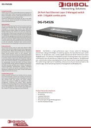
CHAPTER 3 | Using the Web InterfaceNavigating the Web Browser InterfaceNAVIGATING THE WEB BROWSER INTERFACETo access the web-browser interface you must first enter a user name andpassword. By default, the user name is “admin” and there is no password.HOME PAGEWhen your web browser connects with the switch’s web agent, the homepage is displayed as shown below. The home page displays the Main Menuon the left side of the screen and an image of the front panel on the rightside. The Main Menu links are used to navigate to other menus, and displayconfiguration parameters and statistics.Figure 1: Home PageCONFIGURATIONOPTIONSConfigurable parameters have a dialog box or a drop-down list. Once aconfiguration change has been made on a page, be sure to click on theSave button to confirm the new setting. The following table summarizesthe web page configuration buttons.Table 3: Web Page Configuration ButtonsButtonSaveResetActionSets specified values to the system.Cancels specified values and restores currentvalues prior to pressing “Save.”Links directly to web help.– 54 –
CHAPTER 3 | Using the Web InterfaceNavigating the Web Browser InterfaceNOTE: To ensure proper screen refresh, be sure that Internet Explorer isconfigured so that the setting “Check for newer versions of stored pages”reads “Every visit to the page.”Internet Explorer 6.x and earlier: This option is available under the menu“Tools / Internet Options / General / Temporary Internet Files / Settings.”Internet Explorer 7.x: This option is available under “Tools / InternetOptions / General / Browsing History / Settings / Temporary Internet Files.”PANEL DISPLAYThe web agent displays an image of the switch’s ports. The refresh mode isdisabled by default. Click Auto-refresh to refresh the data displayed on thescreen approximately once every 5 seconds, or click Refresh to refresh thescreen right now. Clicking on the image of a port opens the DetailedStatistics page as described on page 203.Figure 2: Front Panel IndicatorsMAIN MENUUsing the onboard web agent, you can define system parameters, manageand control the switch, and all its ports, or monitor network conditions. Thefollowing table briefly describes the selections available from this program.Table 4: Main MenuMenu Description PageConfiguration 61SystemInformation Configures system contact, name and location 61IP Configures IPv4 and SNTP settings 62IPv6 Configures IPv6 and SNTP settings 64NTP Enables NTP, and configures a list of NTP servers 66Ports Configures port connection settings 67Security 70Switch 70Users Configures user names, passwords, and access levels 70Privilege Levels Configures privilege level for specific functions 72– 55 –
CHAPTER 3 | Using the Web InterfaceNavigating the Web Browser InterfaceTable 4: Main Menu (Continued)Menu Description PageAuth MethodConfigures authentication method for management accessvia local database, RADIUS or TACACS+74SSH Configures Secure Shell server 77HTTPS Configures secure HTTP settings 78AccessManagementSets IP addresses of clients allowed management access viaHTTP/HTTPS, SNMP, and Telnet/SSH79SNMP Simple Network Management Protocol 81SystemConfigures read-only and read/write <strong>com</strong>munity strings forSNMP v1/v2c, engine ID for SNMP v3, and trap parameters82Communities Configures <strong>com</strong>munity strings 86Users Configures SNMP v3 users on this switch 87Groups Configures SNMP v3 groups 88Views Configures SNMP v3 views 90AccessNetworkLimit ControlAssigns security model, security level, and read/write viewsto SNMP groupsConfigures port security limit controls, including secureaddress aging; and per port security, including maximumallowed MAC addresses, and response for security breach9192NAS Configures global and port settings for IEEE 802.1X 94ACL Access Control Lists 105Ports Assigns ACL, rate limiter, and other parameters to ports 105Rate Limiters Configures rate limit policies 107Access ControlListDHCPSnoopingConfigures ACLs based on frame type, destination MAC type,VLAN ID, VLAN priority tag; and the action to take formatching packetsDynamic Host Configuration ProtocolEnables DHCP snooping globally; and sets the trust mode foreach port108115Relay Configures DHCP relay information status and policy 118IP Source Guard Filters IP traffic based on static entries in the IP SourceGuard table, or dynamic entries in the DHCP Snooping table 119ConfigurationEnables IP source guard and sets the maximum number ofclients that can learned dynamically119Static Table Adds a static addresses to the source-guard binding table 121ARP Inspection Address Resolution Protocol Inspection 123Configuration Enables inspection globally, and per port 124Static TableAAAAdds static entries based on port, VLAN ID, and source MACaddress and IP address in ARP request packetsConfigures RADIUS authentication server, RADIUSaccounting server, and TACACS+ authentication serversettings125126– 56 –
CHAPTER 3 | Using the Web InterfaceNavigating the Web Browser InterfaceTable 4: Main Menu (Continued)Menu Description PageAggregation 128Static Specifies ports to group into static trunks 129LACP Allows ports to dynamically join trunks 132Spanning Tree 135Bridge SettingsConfigures global bridge settings for STP, RSTP and MSTP;also configures edge port settings for BPDU filtering, BPDUguard, and port error recovery137MSTI Mapping Maps VLANs to a specific MSTP instance 140MSTI Priorities Configures the priority for the CIST and each MISTI 142CIST Ports Configures interface settings for STA 143MSTI Ports Configures interface settings for an MST instance 147IGMP Snooping 149BasicConfigurationVLANConfigurationPort GroupFilteringConfigures global and port settings for multicast filtering 149Configures IGMP snooping per VLAN interface 152Configures multicast groups to be filtered on specified port 153MLD Snooping 154BasicConfigurationVLANConfigurationPort GroupFilteringConfigures Multicast Listener Discovery Snooping 155Configures MLD snooping per VLAN interface 158Configures multicast groups to be filtered on specified port 159MVRConfigures Multicast VLAN Registration, including globalstatus, MVR VLAN, port mode, and immediate leave160LLDP Link Layer Discovery Protocol 163LLDPLLDP-MEDMAC TableConfigures global LLDP timing parameters, and port-specificTLV attributesConfigures LLDP-MED attributes, including device location,emergency call server, and network policy discoveryConfigures address aging, dynamic learning, and staticaddresses163166172VLANs Virtual LANs 174VLAN Membership Configures VLAN groups 175Ports Specifies default PVID and VLAN attributes 176Private VLANsPVLANMembershipConfigures PVLAN groups 178Port IsolationPrevents <strong>com</strong>munications between designated ports withinthe same private VLAN180Voice VLAN 181– 57 –
CHAPTER 3 | Using the Web InterfaceNavigating the Web Browser InterfaceTable 4: Main Menu (Continued)Menu Description PageConfigurationOUIConfigures global settings, including status, voice VLAN ID,VLAN aging time, and traffic priority; also configures portsettings, including the way in which a port is added to theVoice VLAN, and blocking non-VoIP addressesMaps the OUI in the source MAC address of ingress packetsto the VoIP device manufacturer181183QoS 185PortsDSCP RemarkingQoS Control ListConfigures default traffic class, user priority, queue mode,and queue weightsRemarks DSCP values to standard CoS classes, best effort,or expedited forwardingConfigures QoS policies for handling ingress packets basedon Ethernet type, VLAN ID, TCP/UDP port, DSCP, ToS, orVLAN priority tag185187189Rate Limiters Configures ingress and egress rate limits 191Storm ControlSets limits for broadcast, multicast, and unknown unicasttraffic193Mirroring Sets source and target ports for mirroring 194UPnP Enables UPNP and defines timeout values 195Monitor 197System 197InformationDisplays basic system description, switch’s MAC address,system time, and software version197CPU Load Displays graphic scale of CPU utilization 198LogLimits the system messages logged based on severity;displays logged messages199Detailed Log Displays detailed information on each logged message 200Ports 201StateDisplays a graphic image of the front panel indicating activeport connections201Traffic Overview Shows basic Ethernet port statistics 201QoS StatisticsShows the number of packets entering and leaving theegress queues202Detailed Statistics Shows detailed Ethernet port statistics 203Security 205AccessManagementStatisticsNetworkPort SecuritySwitchDisplays the number of packets used to manage the switchvia HTTP, HTTPS, SNMP, Telnet, and SSHShows information about MAC address learning for eachport, including the software module requesting port securityservices, the service state, the current number of learnedaddresses, and the maximum number of secure addressesallowed205206– 58 –
CHAPTER 3 | Using the Web InterfaceNavigating the Web Browser InterfaceTable 4: Main Menu (Continued)Menu Description PagePortShows the entries authorized by port security services,including MAC address, VLAN ID, the service state, timeadded to table, age, and hold state208NAS Shows global and port settings for IEEE 802.1XSwitchShows port status for authentication services, including802.1X security state, last source address used forauthentication, and last ID209Port Displays authentication statistics for the selected port –either for 802.1X protocol or for the remote authenticationserver depending on the authentication method210ACL StatusDHCPShows the status for different security modules which useACL filtering, including ingress port, frame type, andforwarding actionDynamic Host Configuration Protocol214SnoopingStatisticsShows statistics for various types of DHCP protocol packets 215RelayStatisticsARP InspectionIP Source GuardDisplays server and client statistics for packets affected bythe relay information policyDisplays entries in the ARP inspection table, sorted first byport, then VLAN ID, MAC address, and finally IP addressDisplays entries in the IP Source Guard table, sorted first byport, then VLAN ID, MAC address, and finally IP address217219219AAA Authentication, Authorization and Accounting 220RADIUSOverviewRADIUS DetailsDisplays status of configured RADIUS authentication andaccounting serversDisplays the traffic and status associated with eachconfigured RADIUS server220221LACP Link Aggregation Control Protocol 225System StatusPort StatusDisplays administration key and associated local ports foreach partnerDisplays administration key, LAG ID, partner ID, and partnerports for each local port225226Port Statistics Displays statistics for LACP protocol messages 227Spanning Tree 228Bridge Status Displays global bridge and port settings for STA 228Port Status Displays STA role, state, and uptime for each port 230Port Statistics Displays statistics for RSTP, STP and TCN protocol packets 231IGMP SnoopingDisplays statistics related to IGMP packets passed upstreamto the IGMP Querier or downstream to multicast clients232MLD Snooping Multicast Listener Discovery Snooping 234Status Displays MLD querier status and protocol statistics 234Group Information Displays active MLD groups 234MVRShows statistics for IGMP protocol messages used by MVR;also shows information about the interfaces associated withmulticast groups assigned to the MVR VLAN235LLDP Link Layer Discovery Protocol 237– 59 –
CHAPTER 3 | Using the Web InterfaceNavigating the Web Browser InterfaceTable 4: Main Menu (Continued)Menu Description PageNeighborsLLDP-MEDNeighborsPort StatisticsMAC TableDisplays LLDP information about a remote device connectedto a port on this switchDisplays information about a remote device connected to aport on this switch which is advertising LLDP-MED TLVs,including network connectivity device, endpoint device,capabilities, application type, and policyDisplays statistics for all connected remote devices, andstatistics for LLDP protocol packets crossing each portDisplays dynamic and static address entries associated withthe CPU and each port237238241242VLANs Virtual LANs 243VLAN MembershipVLAN PortShows the current port members for all VLANs configured bya selected software moduleShows the VLAN attributes of port members for all VLANsconfigured by a selected software module which uses VLANmanagement, including PVID, VLAN aware, ingress filtering,frame type, egress filtering, and PVID243244Diagnostics 247Ping Tests specified path using IPv4 ping 247Ping6 Tests specified path using IPv6 ping 247VeriPHYPerforms cable diagnostics for all ports or selected port todiagnose any cable faults (short, open etc.) and report thecable length248Maintenance 251Restart Device Restarts the switch 251Factory Defaults Restores factory default settings 252Software UploadUpdates software on the switch with a file specified on themanagement station252Configuration 253SaveUploadSaves configuration settings to a file on the managementstationRestores configuration settings from a file on themanagement station253253– 60 –
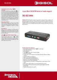
4 CONFIGURING THE SWITCHThis chapter describes all of the basic configuration tasks.CONFIGURING SYSTEM INFORMATIONUse the System Information Configuration page to identify the system byconfiguring contact information, system name, and the location of theswitch.PARAMETERSThese parameters are displayed in the web interface:◆◆◆◆System Contact – Administrator responsible for the system.(Maximum length: 255 characters)System Name – Name assigned to the switch system.(Maximum length: 255 characters)System Location – Specifies the system location.(Maximum length: 255 characters)System Timezone Offset (minutes) – Sets the time zone as an offsetfrom Greenwich Mean Time (GMT). Negative values indicate a zonebefore (east of) GMT, and positive values indicate a zone after (west of)GMT.WEB INTERFACETo configure System Information:1. Click Configuration, System, Information.2. Specify the contact information for the system administrator, as well asthe name and location of the switch. Also indicate the local time zoneby configuring the appropriate offset.3. Click Save.– 61 –
CHAPTER 4 | Configuring the SwitchSetting an IP AddressFigure 3: System Information ConfigurationSETTING AN IP ADDRESSThis section describes how to configure an IP interface for managementaccess to the switch over the network. This switch supports both IP Version4 and Version 6, and can be managed simultaneously through either ofthese address types. You can manually configure a specific IPv4 or IPv6address or direct the switch to obtain an IPv4 address from a DHCP serverwhen it is powered on. An IPv6 address can either be manually configuredor dynamically generated.SETTING AN IPV4ADDRESSUse the IP Configuration page to configure an IPv4 address for the switch.The IP address for the switch is obtained via DHCP by default for VLAN 1.To manually configure an address, you need to change the switch's defaultsettings to values that are <strong>com</strong>patible with your network. You may alsoneed to a establish a default gateway between the switch and managementstations that exist on another network segment.NOTE: An IPv4 address for this switch is obtained via DHCP by default. Ifthe switch does not receive a response from a DHCP server, it will defaultto the IP address 192.168.1.1 and subnet mask 255.255.255.0.You can manually configure a specific IP address, or direct the device toobtain an address from a DHCP server. Valid IPv4 addresses consist of fourdecimal numbers, 0 to 255, separated by periods. Anything other than thisformat will not be accepted by the CLI program.CLI REFERENCES◆ "IP Commands" on page 271– 62 –
CHAPTER 4 | Configuring the SwitchSetting an IP AddressPARAMETERSThe following parameters are displayed on the IP page:IP Configuration◆◆◆◆◆◆DHCP Client – Specifies whether IP functionality is enabled viaDynamic Host Configuration Protocol (DHCP). If DHCP is enabled, IPwill not function until a reply has been received from the server.Requests will be broadcast periodically by the switch for an IP address.DHCP values can include the IP address, subnet mask, and defaultgateway. (Default: Enabled)IP Address – Address of the VLAN specified in the VLAN ID field. Thisshould be the VLAN to which the management station is attached. ValidIP addresses consist of four numbers, 0 to 255, separated by periods.(Default: 192.168.1.1)IP Mask – This mask identifies the host address bits used for routingto specific subnets. (Default: 255.255.255.0)IP Router – IP address of the gateway router between the switch andmanagement stations that exist on other network segments.VLAN ID – ID of the configured VLAN. By default, all ports on theswitch are members of VLAN 1. However, the management station canbe attached to a port belonging to any VLAN, as long as that VLAN hasbeen assigned an IP address. (Range: 1-4095; Default: 1)DNS Server – A Domain Name Server to which client requests formapping host names to IP addresses are forwarded.IP DNS Proxy Configuration◆IP DNS Proxy – If enabled, the switch maintains a local databasebased on previous responses to DNS queries forwarded on behalf ofattached clients. If the required information is not in the local database,the switch forwards the DNS query to a DNS server, stores theresponse in its local cache for future reference, and passes theresponse back to the client.WEB INTERFACETo configure an IP address:1. Click Configuration, System, IP.2. Specify the IPv4 settings, and enable DNS proxy service if required.3. Click Save.– 63 –
CHAPTER 4 | Configuring the SwitchSetting an IP AddressFigure 4: IP ConfigurationSETTING AN IPV6ADDRESSUse the IPv6 Configuration page to configure an IPv6 address formanagement access to the switch.IPv6 includes two distinct address types - link-local unicast and globalunicast. A link-local address makes the switch accessible over IPv6 for alldevices attached to the same local subnet. Management traffic using thiskind of address cannot be passed by any router outside of the subnet. Alink-local address is easy to set up, and may be useful for simple networksor basic troubleshooting tasks. However, to connect to a larger networkwith multiple segments, the switch must be configured with a globalunicast address. A link-local address must be manually configured, but aglobal unicast address can either be manually configured or dynamicallyassigned.CLI REFERENCES◆ "IP Commands" on page 271USAGE GUIDELINES◆ All IPv6 addresses must be formatted according to RFC 2373 “IPv6Addressing Architecture,” using 8 colon-separated 16-bit hexadecimalvalues. One double colon may be used in the address to indicate theappropriate number of zeros required to fill the undefined fields.◆When configuring a link-local address, note that the prefix length isfixed at 64 bits, and the host portion of the default address is based onthe modified EUI-64 (Extended Universal Identifier) form of theinterface identifier (i.e., the physical MAC address). You can manually– 64 –
CHAPTER 4 | Configuring the SwitchSetting an IP Addressconfigure a link-local address by entering the full address with thenetwork prefix FE80.◆To connect to a larger network with multiple subnets, you mustconfigure a global unicast address. There are several alternatives toconfiguring this address type:■■The global unicast address can be automatically configured bytaking the network prefix from router advertisements observed onthe local interface, and using the modified EUI-64 form of theinterface identifier to automatically create the host portion of theaddress. This option can be selected by enabling the AutoConfiguration option.You can also manually configure the global unicast address byentering the full address and prefix length.PARAMETERSThe following parameters are displayed on the IPv6 page:◆◆◆Auto Configuration – Enables stateless autoconfiguration of IPv6addresses on an interface and enables IPv6 functionality on theinterface. The network portion of the address is based on prefixesreceived in IPv6 router advertisement messages, and the host portionis automatically generated using the modified EUI-64 form of theinterface identifier; i.e., the switch's MAC address. (Default: Disabled)Address – <strong>Manual</strong>ly configures a global unicast address by specifyingthe full address and network prefix length (in the Prefix field).(Default: ::192.168.1.1)Prefix – Defines the prefix length as a decimal value indicating howmany contiguous bits (starting at the left) of the address <strong>com</strong>prise theprefix; i.e., the network portion of the address. (Default: 96 bits)Note that the default prefix length of 96 bits specifies that the first sixcolon-separated values <strong>com</strong>prise the network portion of the address.◆◆Router – Sets the IPv6 address of the default next hop router.An IPv6 default gateway must be defined if the management station islocated in a different IPv6 segment.An IPv6 default gateway can only be successfully set when a networkinterface that directly connects to the gateway has been configured onthe switch.VLAN ID – ID of the configured VLAN. By default, all ports on theswitch are members of VLAN 1. However, the management station canbe attached to a port belonging to any VLAN, as long as that VLAN hasbeen assigned an IP address. (Range: 1-4095; Default: 1)– 65 –
CHAPTER 4 | Configuring the SwitchConfiguring NTP ServiceWEB INTERFACETo configure an IPv6 address:1. Click Configuration, System, IPv6.2. Specify the IPv6 settings. The information shown below provides aexample of how to manually configure an IPv6 address.3. Click Save.Figure 5: IPv6 ConfigurationCONFIGURING NTP SERVICEUse the NTP Configuration page to specify the Network Time Protocol (NTP)servers to query for the current time. NTP allows the switch to set itsinternal clock based on periodic updates from an NTP time server.Maintaining an accurate time on the switch enables the system log torecord meaningful dates and times for event entries. If the clock is not set,the switch will only record the time from the factory default set at the lastbootup.When the NTP client is enabled, the switch periodically sends a request fora time update to a configured time server. You can configure up to five timeserver IP addresses. The switch will attempt to poll each server in theconfigured sequence.CLI REFERENCES◆ "IP Commands" on page 271PARAMETERSThe following parameters are displayed in the web interface:◆Mode – Enables or disables NTP client requests.– 66 –
CHAPTER 4 | Configuring the SwitchConfiguring Port Connections◆Server – Sets the IPv4 or IPv6 address for up to five time servers. Theswitch attempts to update the time from the first server, if this fails itattempts an update from the next server in the sequence. The pollinginterval is fixed at 15 minutes.WEB INTERFACETo configure the NTP servers:1. Click Configuration, System, NTP.2. Enter the IP address of up to five time servers.3. Click Save.Figure 6: NTP ConfigurationCONFIGURING PORT CONNECTIONSUse the Port Configuration page to configure the connection parameters foreach port. This page includes options for enabling auto-negotiation ormanually setting the speed and duplex mode, enabling flow control, settingthe maximum frame size, specifying the response to excessive collisions,or enabling power saving mode.CLI REFERENCES◆ "Port Commands" on page 283PARAMETERSThe following parameters are displayed on the Port Configuration page:◆◆Link – Indicates if the link is up or down.Speed – Sets the port speed and duplex mode using auto-negotiationor manual selection. The following options are supported:– 67 –
CHAPTER 4 | Configuring the SwitchConfiguring Port Connections■■■■■■Disabled - Disables the interface. You can disable an interface dueto abnormal behavior (e.g., excessive collisions), and then reenableit after the problem has been resolved. You may also disablean interface for security reasons.Auto - Enables auto-negotiation. When using auto-negotiation, theoptimal settings will be negotiated between the link partners basedon their advertised capabilities.1G FDX - Supports 1 Gbps full-duplex operation100Mbps FDX - Supports 100 Mbps full-duplex operation100Mbps HDX - Supports 100 Mbps half-duplex operation10Mbps FDX - Supports 10 Mbps full-duplex operation■ 10Mbps HDX - Supports 10 Mbps half-duplex operation(Default: Autonegotiation enabled; Advertised capabilities forRJ-45: 1000BASE-T - 10half, 10full, 100half, 100full, 1000full;SFP: 1000BASE-SX/LX/LH - 1000full)NOTE: The 1000BASE-T standard does not support forced mode. Autonegotiationshould always be used to establish a connection over any1000BASE-T port or trunk. If not used, the success of the link processcannot be guaranteed when connecting to other types of switches.◆Flow Control – Flow control can eliminate frame loss by “blocking”traffic from end stations or segments connected directly to the switchwhen its buffers fill. When enabled, back pressure is used for halfduplexoperation and IEEE 802.3-2005 (formally IEEE 802.3x) for fullduplexoperation. (Default: Disabled)When auto-negotiation is used, this parameter indicates the flowcontrol capability advertised to the link partner. When the speed andduplex mode are manually set, the Current Rx field indicates whetherpause frames are obeyed by this port, and the Current Tx field indicatesif pause frames are transmitted from this port.Avoid using flow control on a port connected to a hub unless it isactually required to solve a problem. Otherwise back pressure jammingsignals may degrade overall performance for the segment attached tothe hub.◆◆Maximum Frame – Sets the maximum transfer unit for traffic crossingthe switch. Packets exceeding the maximum frame size are dropped.(Range: 9600-1518 bytes; Default: 9600 bytes)Excessive Collision Mode – Sets the response to take when excessivetransmit collisions are detected on a port.■■Discard - Discards a frame after 16 collisions (default).Restart - Restarts the backoff algorithm after 16 collisions.– 68 –
CHAPTER 4 | Configuring the SwitchConfiguring Port Connections◆Power Control – Adjusts the power provided to ports based on thelength of the cable used to connect to other devices. Only sufficientpower is used to maintain connection requirements.IEEE 802.3 defines the Ethernet standard and subsequent powerrequirements based on cable connections operating at 100 meters.Enabling power saving mode can significantly reduce power used forcable lengths of 20 meters or less, and continue to ensure signalintegrity.The following options are supported:■ Disabled – All power savings mechanisms disabled (default).■■■Enabled – Both link up and link down power savings enabled.ActiPHY – Link down power savings enabled.PerfectReach – Link up power savings enabled.WEB INTERFACETo configure port connection settings:1. Click Configuration, Ports.2. Make any required changes to the connection settings.3. Click Save.Figure 7: Port Configuration– 69 –
CHAPTER 4 | Configuring the SwitchConfiguring SecurityCONFIGURING SECURITYYou can configure this switch to authenticate users logging into the systemfor management access or to control client access to the data ports.Management Access Security – Management access to the switch can becontrolled through local authentication of user names and passwordsstored on the switch, or remote authentication of users via a RADIUS orTACACS+ server. Additional authentication methods includes Secure Shell(SSH), Secure Hypertext Transfer Protocol (HTTPS) over the Secure SocketLayer (SSL), static configuration of client addresses, and SNMP.General Security Measures – This switch supports many methods ofsegregating traffic for clients attached to each of the data ports, and forensuring that only authorized clients gain access to the network. PrivateVLANs and port-based authentication using IEEE 802.1X are <strong>com</strong>monlyused for these purposes. In addition to these methods, several otheroptions of providing client security are supported by this switch. Theseinclude limiting the number of users accessing a port. The addressesassigned to DHCP clients can also be carefully controlled using static ordynamic bindings with DHCP Snooping and IP Source Guard <strong>com</strong>mands.ARP Inspection can also be used to validate the MAC address bindings forARP packets, providing protection against ARP traffic with invalid MAC to IPaddress bindings, which forms the basis for “man-in-the-middle” attacks.CONFIGURING USERACCOUNTSUse the User Configuration page to control management access to theswitch based on manually configured user names and passwords.CLI REFERENCES◆ "User Configuration" on page 312COMMAND USAGE◆ The default administrator name is “admin” with no password.◆The administrator has write access for all parameters governing theonboard agent. You should therefore assign a new administratorpassword as soon as possible, and store it in a safe place.PARAMETERSThese parameters are displayed in the web interface:◆◆◆User Name – The name of the user.(Maximum length: 8 characters; maximum number of users: 16)Password – Specifies the user password.(Range: 0-8 characters plain text, case sensitive)Password (again) – Re-type the string entered in the previous field toensure no errors were made. The switch will not change the password ifthese two fields do not match.– 70 –
CHAPTER 4 | Configuring the SwitchConfiguring Security◆ Privilege Level – Specifies the user level. (Options: 1 - 15)Access to specific functions are controlled through the Privilege Levelsconfiguration page (see page 72). The default settings provide fouraccess levels:■■■■1 – Read access of port status and statistics.5 – Read access of all system functions except for maintenance anddebugging10 – read and write access of all system functions except formaintenance and debugging15 – read and write access of all system functions includingmaintenance and debugging.WEB INTERFACETo show user accounts:1. Click Configuration, System, Switch, Users.Figure 8: Showing User AccountsTo configure a user account:1. Click Configuration, System, Switch, Users.2. Click “Add new user.”3. Enter the user name, password, and privilege level.4. Click Save.– 71 –
CHAPTER 4 | Configuring the SwitchConfiguring SecurityFigure 9: Configuring User AccountsCONFIGURING USERPRIVILEGE LEVELSUse the Privilege Levels page to set the privilege level required to read orconfigure specific software modules or system settings.CLI REFERENCES◆ "Privilege Level Configuration" on page 313PARAMETERSThese parameters are displayed in the web interface:◆Group Name – The name identifying a privilege group. In most cases,a privilege group consists of a single module (e.g., LACP, RSTP or QoS),but a few groups contains more than one module. The followingdescribes the groups which contain multiple modules or access tovarious system settings:■■■■■■■System: Contact, Name, Location, Timezone, Log.Security: Authentication, System Access Management, Port(contains Dot1x port, MAC based and the MAC Address Limit), ACL,HTTPS, SSH, ARP Inspection, and IP source guard.IP: Everything except for ping.Port: Everything except for VeriPHY.Diagnostics: ping and VeriPHY.Maintenance: CLI - System Reboot, System Restore Default,System Password, Configuration Save, Configuration Load andFirmware Load. Web - Users, Privilege Levels and everything inMaintenance.Debug: Only present in CLI.◆Privilege levels – Every privilege level group can be configured toaccess the following modules or system settings: Configuration Readonly,Configuration/Execute Read-write, Status/Statistics Read-only,and Status/Statistics Read-write (e.g., clearing statistics).– 72 –
CHAPTER 4 | Configuring the SwitchConfiguring SecurityThe default settings provide four access levels:■■■■1 – Read access of port status and statistics.5 – Read access of all system functions except for maintenance anddebugging10 – read and write access of all system functions except formaintenance and debugging15 – read and write access of all system functions includingmaintenance and debugging.WEB INTERFACETo configure privilege levels:1. Click Configuration, Security, Switch, Privilege Levels.2. Set the required privilege level for any software module or functionalgroup.3. Click Save.– 73 –
CHAPTER 4 | Configuring the SwitchConfiguring SecurityFigure 10: Configuring Privilege LevelsCONFIGURING THEAUTHENTICATIONMETHOD FORMANAGEMENT ACCESSUse the Authentication Method Configuration page to specify theauthentication method for controlling management access through theconsole, Telnet, SSH or HTTP/HTTPS. Access can be based on the (local)user name and password configured on the switch, or can be controlledwith a RADIUS or TACACS+ remote access authentication server. Note thatthe RADIUS servers used to authenticate client access for IEEE 802.1X portauthentication are also configured on this page (see page 94).Remote Authentication Dial-in User Service (RADIUS) and Terminal AccessController Access Control System Plus (TACACS+) are logon authenticationprotocols that use software running on a central server to control access toRADIUS-aware or TACACS-aware devices on the network. Anauthentication server contains a database of multiple user name/passwordpairs with associated privilege levels for each user that requiresmanagement access to the switch.– 74 –
CHAPTER 4 | Configuring the SwitchConfiguring SecurityFigure 11: Authentication Server OperationWebTelnetconsoleRADIUS/TACACS+server1. Client attempts management access.2. Switch contacts authentication server.3. Authentication server challenges client.4. Client responds with proper password or key.5. Authentication server approves access.6. Switch grants management access.CLI REFERENCES◆ "Protocol Authentication Commands" on page 316USAGE GUIDELINES◆ The switch supports the following authentication services:■■■Authorization of users that access the Telnet, SSH, the web, orconsole management interfaces on the switch.Accounting for users that access the Telnet, SSH, the web, orconsole management interfaces on the switch.Accounting for IEEE 802.1X authenticated users that access thenetwork through the switch. This accounting can be used to providereports, auditing, and billing for services that users have accessed.◆◆By default, management access is always checked against theauthentication database stored on the local switch. If a remoteauthentication server is used, you must specify the authenticationmethod and the corresponding parameters for the remoteauthentication protocol on the Network Access Server Configurationpage. Local and remote logon authentication can be used to controlmanagement access via Telnet, SSH, a web browser, or the consoleinterface.When using RADIUS or TACACS+ logon authentication, the user nameand password must be configured on the authentication server. Theencryption methods used for the authentication process must also beconfigured or negotiated between the authentication server and logonclient. This switch can pass authentication messages between theserver and client that have been encrypted using MD5 (Message-Digest5), TLS (Transport Layer Security), or TTLS (Tunneled Transport LayerSecurity).– 75 –
CHAPTER 4 | Configuring the SwitchConfiguring SecurityNOTE: This guide assumes that RADIUS and TACACS+ servers have alreadybeen configured to support AAA. The configuration of RADIUS andTACACS+ server software is beyond the scope of this guide. Refer to thedocumentation provided with the RADIUS and TACACS+ server software.PARAMETERSThe following parameters are displayed on the Authentication MethodConfiguration page:◆◆◆Client – Specifies how the administrator is authenticated when logginginto the switch via Telnet, SSH, a web browser, or the console interface.Authentication Method – Selects the authentication method.(Options: None, Local, RADIUS, TACACS+; Default: Local)Selecting the option “None” disables access through the specifiedmanagement interface.Fallback – Uses the local user database for authentication if none ofthe configured authentication servers are alive. This is only possible ifthe Authentication Method is set to something else than “none” or“local.”WEB INTERFACETo configure authentication for management access:1. Click Configuration, Security, Switch, Auth Method.2. Configure the authentication method for management client types, andspecify whether or not to fallback to local authentication if no remoteauthentication server is available.3. Click Save.Figure 12: Authentication Method for Management Access– 76 –
CHAPTER 4 | Configuring the SwitchConfiguring SecurityCONFIGURING SSH Use the SSH Configuration page to configure access to the Secure Shell(SSH) management interface. SSH provides remote management access tothis switch as a secure replacement for Telnet. When the client contacts theswitch via the SSH protocol, the switch generates a public-key that theclient uses along with a local user name and password for accessauthentication. SSH also encrypts all data transfers passing between theswitch and SSH-enabled management station clients, and ensures thatdata traveling over the network arrives unaltered.CLI REFERENCES◆ "SSH Commands" on page 318USAGE GUIDELINES◆ You need to install an SSH client on the management station to accessthe switch for management via the SSH protocol. The switch supportsboth SSH Version 1.5 and 2.0 clients.◆◆SSH service on this switch only supports password authentication. Thepassword can be authenticated either locally or via a RADIUS orTACACS+ remote authentication server, as specified on the AuthMethod menu (page 74).To use SSH with password authentication, the host public key must stillbe given to the client, either during initial connection or manuallyentered into the known host file. However, you do not need to configurethe client's keys.The SSH service on the switch supports up to four client sessions. Themaximum number of client sessions includes both current Telnetsessions and SSH sessions.PARAMETERSThe following parameters are displayed on the SSH Configuration page:◆Mode - Allows you to enable/disable SSH service on the switch.(Default: Disabled)WEB INTERFACETo configure SSH:1. Click Configuration, SSH.2. Enable SSH if required.3. Click Save.– 77 –
CHAPTER 4 | Configuring the SwitchConfiguring SecurityFigure 13: SSH ConfigurationCONFIGURING HTTPS Use the HTTPS Configuration page to enable the Secure Hypertext TransferProtocol (HTTPS) over the Secure Socket Layer (SSL). HTTPS providessecure access (i.e., an encrypted connection) to the switch's web interface.CLI REFERENCES◆ "HTTPS Commands" on page 319USAGE GUIDELINES◆ If you enable HTTPS, you must indicate this in the URL that you specifyin your browser: https://device[:port-number]◆◆When you start HTTPS, the connection is established in this way:■■■■The client authenticates the server using the server’s digitalcertificate.The client and server negotiate a set of security protocols to use forthe connection.The client and server generate session keys for encrypting anddecrypting data.The client and server establish a secure encrypted connection.A padlock icon should appear in the status bar for Internet Explorer5.x or above, Netscape 6.2 or above, and Mozilla Firefox 2.0.0.0 orabove.The following web browsers and operating systems currently supportHTTPS:Table 5: HTTPS System SupportWeb BrowserInternet Explorer 5.0 or laterNetscape 6.2 or laterMozilla Firefox 2.0 or laterOperating SystemWindows 98,Windows NT (with service pack 6a),Windows 2000, Windows XP, Windows Vista, Windows7Windows 98,Windows NT (with service pack 6a),Windows 2000, Windows XP, Windows Vista, Solaris2.6Windows 2000, Windows XP, Windows Vista, Linux– 78 –
CHAPTER 4 | Configuring the SwitchConfiguring SecurityPARAMETERSThe following parameters are displayed on the HTTPS Configuration page:◆◆Mode - Enables HTTPS service on the switch. (Default: Disabled)Automatic Redirect - Sets the HTTPS redirect mode operation. Whenenabled, management access to the HTTP web interface for the switchare automatically redirected to HTTPS. (Default: Disabled)WEB INTERFACETo configure HTTPS:1. Click Configuration, HTTPS.2. Enable HTTPS if required and set the Automatic Redirect mode.3. Click Save.Figure 14: HTTPS ConfigurationFILTERING IPADDRESSES FORMANAGEMENT ACCESSUse the Access Management Configuration page to create a list of up to 16IP addresses or IP address groups that are allowed management access tothe switch through the web interface, SNMP, or Telnet.The management interfaces are open to all IP addresses by default. Onceyou add an entry to a filter list, access to that interface is restricted to thespecified addresses. If anyone tries to access a management interface onthe switch from an invalid address, the switch will reject the connection.CLI REFERENCES◆ "Management Access Commands" on page 322PARAMETERSThe following parameters are displayed on the Access Management page:◆◆◆Mode – Enables or disables filtering of management access based onconfigured IP addresses. (Default: Disabled)Start IP Address – The starting address of a range.End IP Address – The ending address of a range.– 79 –
CHAPTER 4 | Configuring the SwitchConfiguring Security◆◆◆HTTP/HTTPS – Filters IP addresses for access to the web interfaceover standard HTTP, or over HTTPS which uses the Secure Socket Layer(SSL) protocol to provide an encrypted connection.SNMP – Filters IP addresses for access through SNMP.TELNET/SSH – Filters IP addresses for access through Telnet, orthrough Secure Shell which provides authentication and encryption.WEB INTERFACETo configure addresses allowed access to management interfaces on theswitch:1. Click Configuration, Security, Switch, Access Management.2. Set the Mode to Enabled.3. Click “Add new entry.”4. Enter the start and end of an address range.5. Mark the protocols to restrict based on the specified address range. Thefollowing example shows how to restrict management access for allprotocols to a specific address range.6. Click Save.Figure 15: Access Management Configuration– 80 –
CHAPTER 4 | Configuring the SwitchConfiguring SecurityUSING SIMPLENETWORKMANAGEMENTPROTOCOLSimple Network Management Protocol (SNMP) is a <strong>com</strong>munication protocoldesigned specifically for managing devices on a network. Equipment<strong>com</strong>monly managed with SNMP includes switches, routers and host<strong>com</strong>puters. SNMP is typically used to configure these devices for properoperation in a network environment, as well as to monitor them to evaluateperformance or detect potential problems.Managed devices supporting SNMP contain software, which runs locally onthe device and is referred to as an agent. A defined set of variables, knownas managed objects, is maintained by the SNMP agent and used to managethe device. These objects are defined in a Management Information Base(MIB) that provides a standard presentation of the information controlledby the agent. SNMP defines both the format of the MIB specifications andthe protocol used to access this information over the network.The switch includes an onboard agent that supports SNMP versions 1, 2c,and 3. This agent continuously monitors the status of the switch hardware,as well as the traffic passing through its ports. A network managementstation can access this information using software such as HP OpenView.Access to the onboard agent from clients using SNMP v1 and v2c iscontrolled by <strong>com</strong>munity strings. To <strong>com</strong>municate with the switch, themanagement station must first submit a valid <strong>com</strong>munity string forauthentication.Access to the switch using from clients using SNMPv3 provides additionalsecurity features that cover message integrity, authentication, andencryption; as well as controlling user access to specific areas of the MIBtree.The SNMPv3 security structure consists of security models, with eachmodel having it's own security levels. There are three security modelsdefined, SNMPv1, SNMPv2c, and SNMPv3. Users are assigned to “groups”that are defined by a security model and specified security levels. Eachgroup also has a defined security access to set of MIB objects for readingand writing, which are known as “views.” The switch has a default view (allMIB objects) and default groups defined for security models v1 and v2c.The following table shows the security models and levels available and thesystem default settings.Table 6: SNMP Security Models and LevelsModel Level Community String Group Read View Write View Securityv1v1v1v2cnoAuthNoPrivnoAuthNoPrivnoAuthNoPrivnoAuthNoPrivpublic default_ro_group default_view none Community string onlyprivate default_rw_group default_view default_view Community string onlyuser defined user defined user defined user defined Community string onlypublic default_ro_group default_view none Community string only– 81 –
CHAPTER 4 | Configuring the SwitchConfiguring SecurityTable 6: SNMP Security Models and Levels (Continued)Model Level Community String Group Read View Write View Securityv2cv2cv3v3noAuthNoPrivnoAuthNoPrivnoAuthNoPrivAuthNoPrivprivate default_rw_group default_view default_view Community string onlyuser defined user defined user defined user defined Community string onlyuser defined default_rw_group default_view default_view A user name match onlyuser defined user defined user defined user defined Provides user authenticationvia MD5 or SHA algorithmsv3 Auth Priv user defined user defined user defined user defined Provides user authenticationvia MD5 or SHA algorithmsand data privacy using DES56-bit encryptionNOTE: The predefined default groups and view can be deleted from thesystem. You can then define customized groups and views for the SNMPclients that require access.CONFIGURING SNMP SYSTEM AND TRAP SETTINGSUse the SNMP System Configuration page to configure basic settings andtraps for SNMP. To manage the switch through SNMP, you must first enablethe protocol and configure the basic access parameters. To issue trapmessages, the trap function must also be enabled and the destination hostspecified.CLI REFERENCES◆ "SNMP Commands" on page 326PARAMETERSThe following parameters are displayed on the SNMP System Configurationpage:SNMP System Configuration◆Mode - Enables or disables SNMP service. (Default: Disabled)◆ Version - Specifies the SNMP version to use. (Options: SNMP v1,SNMP v2c, SNMP v3; Default: SNMP v2c)◆Read Community - The <strong>com</strong>munity used for read-only access to theSNMP agent. (Range: 0-255 characters, ASCII characters 33-126 only;Default: public)This parameter only applies to SNMPv1 and SNMPv2c. SNMPv3 uses theUser-based Security Model (USM) for authentication and privacy. This<strong>com</strong>munity string is associated with SNMPv1 or SNMPv2 clients in theSNMPv3 Communities table (page 86).– 82 –
CHAPTER 4 | Configuring the SwitchConfiguring Security◆◆Write Community - The <strong>com</strong>munity used for read/write access to theSNMP agent. (Range: 0-255 characters, ASCII characters 33-126 only;Default: private)This parameter only applies to SNMPv1 and SNMPv2c. SNMPv3 uses theUser-based Security Model (USM) for authentication and privacy. This<strong>com</strong>munity string is associated with SNMPv1 or SNMPv2 clients in theSNMPv3 Communities table (page 86).Engine ID - The SNMPv3 engine ID. (Range: 10-64 hex digits,excluding a string of all 0’s or all F’s; Default: 800007e5017f000001)An SNMPv3 engine is an independent SNMP agent that resides on theswitch. This engine protects against message replay, delay, andredirection. The engine ID is also used in <strong>com</strong>bination with userpasswords to generate the security keys for authenticating andencrypting SNMPv3 packets.A local engine ID is automatically generated that is unique to theswitch. This is referred to as the default engine ID. If the local engineID is deleted or changed, all local SNMP users will be cleared. You willneed to reconfigure all existing users.SNMP Trap Configuration◆◆◆◆◆◆◆Trap Mode - Enables or disables SNMP traps. (Default: Disabled)You should enable SNMP traps so that key events are reported by thisswitch to your management station. Traps indicating status changescan be issued by the switch to the specified trap manager by sendingauthentication failure messages and other trap messages.Trap Version - Indicates if the target user is running SNMP v1, v2c, orv3. (Default: SNMP v1)Trap Community - Specifies the <strong>com</strong>munity access string to use whensending SNMP trap packets. (Range: 0-255 characters, ASCIIcharacters 33-126 only; Default: public)Trap Destination Address - IPv4 address of the management stationto receive notification messages.Trap Destination IPv6 Address - IPv6 address of the managementstation to receive notification messages. An IPv6 address must beformatted according to RFC 2373 “IPv6 Addressing Architecture,” using8 colon-separated 16-bit hexadecimal values. One double colon may beused to indicate the appropriate number of zeros required to fill theundefined fields.Trap Authentication Failure - Issues a notification message tospecified IP trap managers whenever authentication of an SNMPrequest fails. (Default: Enabled)Trap Link-up and Link-down - Issues a notification messagewhenever a port link is established or broken. (Default: Enabled)– 83 –
CHAPTER 4 | Configuring the SwitchConfiguring Security◆◆◆◆◆Trap Inform Mode - Enables or disables sending notifications asinform messages. Note that this option is only available for version 2cand 3 hosts. (Default: traps are used)The recipient of a trap message does not send a response to the switch.Traps are therefore not as reliable as inform messages, which include arequest for acknowledgement of receipt. Informs can be used to ensurethat critical information is received by the host. However, note thatinforms consume more system resources because they must be kept inmemory until a response is received. Informs also add to networktraffic. You should consider these effects when deciding whether toissue notifications as traps or informs.Trap Inform Timeout - The number of seconds to wait for anacknowledgment before resending an inform message. (Range: 0-2147seconds; Default: 1 second)Trap Inform Retry Times - The maximum number of times to resendan inform message if the recipient does not acknowledge receipt.(Range: 0-255; Default: 5)Trap Probe Security Engine ID (SNMPv3) - Specifies whether or notto use the engine ID of the SNMP trap probe in trap and informmessages. (Default: Enabled)Trap Security Engine ID (SNMPv3) - Indicates the SNMP trap securityengine ID. SNMPv3 sends traps and informs using USM forauthentication and privacy. A unique engine ID for these traps andinforms is needed. When “Trap Probe Security Engine ID” is enabled,the ID will be probed automatically. Otherwise, the ID specified in thisfield is used. (Range: 10-64 hex digits, excluding a string of all 0’s or allF’s)NOTE: The Trap Probe Security Engine ID must be disabled before anengine ID can be manually entered in this field.◆Trap Security Name (SNMPv3) - Indicates the SNMP trap securityname. SNMPv3 traps and informs use USM for authentication andprivacy. A unique security name is needed when SNMPv3 traps orinforms are enabled.NOTE: To select a name from this field, first enter an SNMPv3 user with thesame Trap Security Engine ID in the SNMPv3 Users Configuration menu(see "Configuring SNMPv3 Users" on page 87).WEB INTERFACETo configure SNMP system and trap settings:1. Click Configuration, Security, Switch, SNMP, System.– 84 –
CHAPTER 4 | Configuring the SwitchConfiguring Security2. In the SNMP System Configuration table, set the Mode to Enabled toenable SNMP service on the switch, specify the SNMP version to use,change the <strong>com</strong>munity access strings if required, and set the engine IDif SNMP version 3 is used.3. In the SNMP Trap Configuration table, enable the Trap Mode to allowthe switch to send SNMP traps. Specify the trap version, trap<strong>com</strong>munity, and IP address of the management station that will receivetrap messages either as an IPv4 or IPv6 address. Select the trap typesto issue, and set the trap inform settings for SNMP v2c or v3 clients.For SNMP v3 clients, configure the security engine ID and securityname used in v3 trap and inform messages.4. Click Save.Figure 16: SNMP System Configuration– 85 –
CHAPTER 4 | Configuring the SwitchConfiguring SecuritySETTING SNMPV3 COMMUNITY ACCESS STRINGSUse the SNMPv3 Community Configuration page to set <strong>com</strong>munity accessstrings. All <strong>com</strong>munity strings used to authorize access by SNMP v1 andv2c clients should be listed in the SNMPv3 Communities Configurationtable. For security reasons, you should consider removing the defaultstrings.CLI REFERENCES◆ "SNMP Commands" on page 326PARAMETERSThe following parameters are displayed on the SNMPv3 CommunitiesConfiguration page:◆◆◆Community - Specifies the <strong>com</strong>munity strings which allow access tothe SNMP agent. (Range: 1-32 characters, ASCII characters 33-126only; Default: public, private)For SNMPv3, these strings are treated as a Security Name, and aremapped as an SNMPv1 or SNMPv2 <strong>com</strong>munity string in the SNMPv3Groups Configuration table (see "Configuring SNMPv3 Groups" onpage 88).Source IP - Specifies the source address of an SNMP client.Source Mask - Specifies the address mask for the SNMP client.WEB INTERFACETo configure SNMP <strong>com</strong>munity access strings:1. Click Configuration, Security, Switch, SNMP, Communities.2. Set the IP address and mask for the default <strong>com</strong>munity strings.Otherwise, you should consider deleting these strings for securityreasons.3. Add any new <strong>com</strong>munity strings required for SNMPv1 or v2 clients thatneed to access the switch, along with the source address and addressmask for each client.4. Click Save.Figure 17: SNMPv3 Community Configuration– 86 –
CHAPTER 4 | Configuring the SwitchConfiguring SecurityCONFIGURING SNMPV3 USERSUse the SNMPv3 User Configuration page to define a unique name andremote engine ID for each SNMPv3 user. Users must be configured with aspecific security level, and the types of authentication and privacyprotocols to use.NOTE: Any user assigned through this page is associated with the groupassigned to the USM Security Model on the SNMPv3 Groups Configurationpage (page 88), and the views assigned to that group in the SNMPv3Access Configuration page (page 91).CLI REFERENCES◆ "SNMP Commands" on page 326PARAMETERSThe following parameters are displayed on the SNMPv3 Users Configurationpage:◆◆◆◆Engine ID - The engine identifier for the SNMP agent on the remotedevice where the user resides. (Range: 10-64 hex digits, excluding astring of all 0’s or all F’s)To send inform messages to an SNMPv3 user on a remote device, youmust first specify the engine identifier for the SNMP agent on theremote device where the user resides. The remote engine ID is used to<strong>com</strong>pute the security digest for authenticating and encrypting packetssent to a user on the remote host.SNMP passwords are localized using the engine ID of the authoritativeagent. For informs, the authoritative SNMP agent is the remote agent.You therefore need to configure the remote agent's SNMP engine IDbefore you can send proxy requests or informs to it. (See "ConfiguringSNMP System and Trap Settings" on page 82.)User Name - The name of user connecting to the SNMP agent.(Range: 1-32 characters, ASCII characters 33-126 only)Security Level - The security level assigned to the user:■■■NoAuth, NoPriv - There is no authentication or encryption used inSNMP <strong>com</strong>munications. (This is the default for SNMPv3.)Auth, NoPriv - SNMP <strong>com</strong>munications use authentication, but thedata is not encrypted.Auth, Priv - SNMP <strong>com</strong>munications use both authentication andencryption.Authentication Protocol - The method used for user authentication.(Options: None, MD5, SHA; Default: MD5)– 87 –
CHAPTER 4 | Configuring the SwitchConfiguring Security◆◆◆Authentication Password - A plain text string identifying theauthentication pass phrase. (Range: 1-32 characters for MD5, 8-40characters for SHA)Privacy Protocol - The encryption algorithm use for data privacy; only56-bit DES is currently available. (Options: None, DES; Default: DES)Privacy Password - A string identifying the privacy pass phrase.(Range: 8-40 characters, ASCII characters 33-126 only)WEB INTERFACETo configure SNMPv3 users:1. Click Configuration, Security, Switch, SNMP, Users.2. Click “Add new user” to configure a user name.3. Enter a remote Engine ID of up to 64 hexadecimal characters4. Define the user name, security level, authentication and privacysettings.5. Click Save.Figure 18: SNMPv3 User ConfigurationCONFIGURING SNMPV3 GROUPSUse the SNMPv3 Group Configuration page to configure SNMPv3 groups.An SNMPv3 group defines the access policy for assigned users, restrictingthem to specific read and write views as defined on the SNMPv3 AccessConfiguration page (page 91). You can use the pre-defined default groups,or create a new group and the views authorized for that group.CLI REFERENCES◆ "SNMP Commands" on page 326PARAMETERSThe following parameters are displayed on the SNMPv3 GroupsConfiguration page:◆Security Model - The user security model. (Options: SNMP v1, v2c, orthe User-based Security Model – usm).– 88 –
CHAPTER 4 | Configuring the SwitchConfiguring Security◆◆Security Name - The name of user connecting to the SNMP agent.(Range: 1-32 characters, ASCII characters 33-126 only)The options displayed for this parameter depend on the selectedSecurity Model. For SNMP v1 and v2c, the switch displays the namesconfigured on the SNMPv3 Communities Configuration menu (seepage 86). For USM (or SNMPv3), the switch displays the namesconfigured with the local engine ID in the SNMPv3 Users Configurationmenu (see page 87). To modify an entry for USM, the current entrymust first be deleted.Group Name - The name of the SNMP group. (Range: 1-32 characters,ASCII characters 33-126 only)WEB INTERFACETo configure SNMPv3 groups:1. Click Configuration, Security, Switch, SNMP, Groups.2. Click “Add new group” to set up a new group.3. Select a security model.4. Select the security name. For SNMP v1 and v2c, the security namesdisplayed are based on the those configured in the SNMPv3Communities menu. For USM, the security names displayed are basedon the those configured in the SNMPv3 Users Configuration menu.5. Enter a group name. Note that the views assigned to a group must bespecified on the SNMP Accesses Configuration menu (see page 91).6. Click Save.Figure 19: SNMPv3 Group Configuration– 89 –
CHAPTER 4 | Configuring the SwitchConfiguring SecurityCONFIGURING SNMPV3 VIEWSUse the SNMPv3 View Configuration page to define views which restrictuser access to specified portions of the MIB tree. The predefined view“default_view” includes access to the entire MIB tree.CLI REFERENCES◆ "SNMP Commands" on page 326PARAMETERSThe following parameters are displayed on the SNMPv3 ViewsConfiguration page:◆◆◆View Name - The name of the SNMP view. (Range: 1-32 characters,ASCII characters 33-126 only)View Type - Indicates if the object identifier of a branch within the MIBtree is included or excluded from the SNMP view. Generally, if the viewtype of an entry is “excluded,” another entry of view type “included”should exist and its OID subtree should overlap the “excluded” viewentry.OID Subtree - Object identifiers of branches within the MIB tree. Notethat the first character must be a period (.). Wild cards can be used tomask a specific portion of the OID string using an asterisk.(Length: 1-128)WEB INTERFACETo configure SNMPv3 views:1. Click Configuration, Security, Switch, SNMP, Views.2. Click “Add new view” to set up a new view.3. Enter the view name, view type, and OID subtree.4. Click Save.Figure 20: SNMPv3 View Configuration– 90 –
CHAPTER 4 | Configuring the SwitchConfiguring SecurityCONFIGURING SNMPV3 GROUP ACCESS RIGHTSUse the SNMPv3 Access Configuration page to assign portions of the MIBtree to which each SNMPv3 group is granted access. You can assign morethan one view to a group to specify access to different portions of the MIBtree.CLI REFERENCES◆ "SNMP Commands" on page 326PARAMETERSThe following parameters are displayed on the SNMPv3 AccessConfiguration page:◆◆◆Group Name - The name of the SNMP group. (Range: 1-32 characters,ASCII characters 33-126 only)Security Model - The user security model. (Options: any, v1, v2c, orthe User-based Security Model – usm; Default: any)Security Level - The security level assigned to the group:■■■NoAuth, NoPriv - There is no authentication or encryption used inSNMP <strong>com</strong>munications. (This is the default for SNMPv3.)Auth, NoPriv - SNMP <strong>com</strong>munications use authentication, but thedata is not encrypted.Auth, Priv - SNMP <strong>com</strong>munications use both authentication andencryption.◆ Read View Name - The configured view for read access. (Range: 1-32characters, ASCII characters 33-126 only)◆Write View Name - The configured view for write access.(Range: 1-32 characters, ASCII characters 33-126 only)WEB INTERFACETo configure SNMPv3 group access rights:1. Click Configuration, Security, Switch, SNMP, Access.2. Click Add New Access to create a new entry.3. Specify the group name, security settings, read view, and write view.4. Click Save.– 91 –
CHAPTER 4 | Configuring the SwitchConfiguring SecurityFigure 21: SNMPv3 Access ConfigurationCONFIGURING PORTLIMIT CONTROLSUse the Port Limit Control Configuration page to limit the number of usersaccessing a given port. A user is identified by a MAC address and VLAN ID.If Limit Control is enabled on a port, the maximum number of users on theport is restricted to the specified limit. If this number is exceeded, theswitch makes the specified response.CLI REFERENCES◆ "Port Security Limit Control" on page 349PARAMETERSThe following parameters are displayed on the Port Limit ControlConfiguration page:System Configuration◆◆Mode – Enables or disables Limit Control is globally on the switch. Ifglobally disabled, other modules may still use the underlyingfunctionality, but limit checks and corresponding actions are disabled.Aging Enabled – If enabled, secured MAC addresses are subject toaging as discussed under Aging Period.With aging enabled, a timer is started once the end-host gets secured.When the timer expires, the switch starts looking for frames from theend-host, and if such frames are not seen within the next Aging Period,the end-host is assumed to be disconnected, and the correspondingresources are freed on the switch.◆Aging Period – If Aging Enabled is checked, then the aging period iscontrolled with this parameter. If other modules are using theunderlying port security for securing MAC addresses, they may haveother requirements for the aging period. The underlying port securitywill use the shortest requested aging period of all modules that use thisfunctionality. (Range: 10-10,000,000 seconds; Default: 3600 seconds)Port Configuration◆ Port – Port identifier. (Range: 1-28)– 92 –
CHAPTER 4 | Configuring the SwitchConfiguring Security◆◆◆◆Mode – Controls whether Limit Control is enabled on this port. Boththis and the global Mode must be set to Enabled for Limit Control to bein effect. Notice that other modules may still use the underlying portsecurity features without enabling Limit Control on a given port.Limit – The maximum number of MAC addresses that can be securedon this port. This number cannot exceed 1024. If the limit is exceeded,the corresponding action is taken.The switch is “initialized” with a total number of MAC addresses fromwhich all ports draw whenever a new MAC address is seen on a PortSecurity-enabled port. Since all ports draw from the same pool, it mayhappen that a configured maximum cannot be granted if the remainingports have already used all available MAC addresses.Action – If Limit is reached, the switch can take one of the followingactions:■■■■None: Do not allow more than the specified Limit of MAC addresseson the port, but take no further action.Trap: If Limit + 1 MAC addresses is seen on the port, send an SNMPtrap. If Aging is disabled, only one SNMP trap will be sent, but withAging enabled, new SNMP traps will be sent every time the limit isexceeded.Shutdown: If Limit + 1 MAC addresses is seen on the port, shutdown the port. This implies that all secured MAC addresses will beremoved from the port, and no new addresses will be learned. Evenif the link is physically disconnected and reconnected on the port(by disconnecting the cable), the port will remain shut down. Thereare three ways to re-open the port:■■■Boot the switch,Disable and re-enable Limit Control on the port or the switch,Click the Reopen button.Trap & Shutdown: If Limit + 1 MAC addresses is seen on the port,both the “Trap” and the “Shutdown” actions described above will betaken.State – This column shows the current state of the port as seen fromthe Limit Control's point of view. The state takes one of four values:■■■■Disabled: Limit Control is either globally disabled or disabled on theport.Ready: The limit is not yet reached. This can be shown for allActions.Limit Reached: Indicates that the limit is reached on this port. Thisstate can only be shown if Action is set to None or Trap.Shutdown: Indicates that the port is shut down by the Limit Controlmodule. This state can only be shown if Action is set to Shutdown orTrap & Shutdown.– 93 –
CHAPTER 4 | Configuring the SwitchConfiguring Security◆Re-open – If a port is shut down by this module, you may reopen it byclicking this button, which will only be enabled if this is the case. Forother methods, refer to Shutdown in the Action section.Note, that clicking the Reopen button causes the page to be refreshed,so non-<strong>com</strong>mitted changes will be lost.WEB INTERFACETo configure port limit controls:1. Click Configuration, Security, Network, Limit Control.2. Set the system configuration parameters to globally enable or disablelimit controls, and configure address aging as required.3. Set limit controls for any port, including status, maximum number ofaddresses allowed, and the response to a violation.4. Click Save.Figure 22: Port Limit Control ConfigurationCONFIGURINGAUTHENTICATIONTHROUGH NETWORKACCESS SERVERSNetwork switches can provide open and easy access to network resourcesby simply attaching a client PC. Although this automatic configuration andaccess is a desirable feature, it also allows unauthorized personnel to easilyintrude and possibly gain access to sensitive network data.Use the Network Access Server Configuration page to configure IEEE802.1X port-based and MAC-based authentication settings. The 802.1Xstandard defines a port-based access control procedure that preventsunauthorized access to a network by requiring users to first submitcredentials for authentication. Access to all switch ports in a network canbe centrally controlled from a server, which means that authorized users– 94 –
CHAPTER 4 | Configuring the SwitchConfiguring Securitycan use the same credentials for authentication from any point within thenetwork.Figure 23: Using Port Security802.1xclientRADIUSserver1. Client attempts to access a switch port.2. Switch sends client an identity request.3. Client sends back identity information.4. Switch forwards this to authentication server.5. Authentication server challenges client.6. Client responds with proper credentials.7. Authentication server approves access.8. Switch grants client access to this port.This switch uses the Extensible Authentication Protocol over LANs (EAPOL)to exchange authentication protocol messages with the client, and aremote RADIUS authentication server to verify user identity and accessrights. These backend servers are configured on the AAA menu (seepage 126).When a client (i.e., Supplicant) connects to a switch port, the switch (i.e.,Authenticator) responds with an EAPOL identity request. The clientprovides its identity (such as a user name) in an EAPOL response to theswitch, which it forwards to the RADIUS server. The RADIUS server verifiesthe client identity and sends an access challenge back to the client. TheEAP packet from the RADIUS server contains not only the challenge, butthe authentication method to be used. The client can reject theauthentication method and request another, depending on theconfiguration of the client software and the RADIUS server. The encryptionmethod used by IEEE 802.1X to pass authentication messages can be MD5(Message-Digest 5), TLS (Transport Layer Security), PEAP (ProtectedExtensible Authentication Protocol), or TTLS (Tunneled Transport LayerSecurity). However, note that the only encryption method supported byMAC-Based authentication is MD5. The client responds to the appropriatemethod with its credentials, such as a password or certificate. The RADIUSserver verifies the client credentials and responds with an accept or rejectpacket. If authentication is successful, the switch allows the client toaccess the network. Otherwise, network access is denied and the portremains blocked.The operation of 802.1X on the switch requires the following:◆ The switch must have an IP address assigned (see page 62).– 95 –
CHAPTER 4 | Configuring the SwitchConfiguring Security◆◆◆◆RADIUS authentication must be enabled on the switch and the IPaddress of the RADIUS server specified. Backend RADIUS servers areconfigured on the Authentication Configuration page (see page 126).802.1X / MAC-based authentication must be enabled globally for theswitch.The Admin State for each switch port that requires client authenticationmust be set to 802.1X or MAC-based.When using 802.1X authentication:■Each client that needs to be authenticated must have dot1x clientsoftware installed and properly configured.■ When using 802.1X authentication, the RADIUS server and 802.1Xclient must support EAP. (The switch only supports EAPOL in orderto pass the EAP packets from the server to the client.)■The RADIUS server and client also have to support the same EAPauthentication type - MD5, PEAP, TLS, or TTLS. (Native support forthese encryption methods is provided in Windows 7, Windows Vista,Windows XP, and in Windows 2000 with Service Pack 4. To supportthese encryption methods in Windows 95 and 98, you can use theAEGIS dot1x client or other <strong>com</strong>parable client software.)MAC-based authentication allows for authentication of more than one useron the same port, and does not require the user to have special 802.1Xsoftware installed on his system. The switch uses the client's MAC addressto authenticate against the backend server. However, note that intruderscan create counterfeit MAC addresses, which makes MAC-basedauthentication less secure than 802.1X authentication.CLI REFERENCES◆ "Network Access Server Commands" on page 354USAGE GUIDELINESWhen 802.1X is enabled, you need to configure the parameters for theauthentication process that runs between the client and the switch (i.e.,authenticator), as well as the client identity lookup process that runsbetween the switch and authentication server. These parameters aredescribed in this section.PARAMETERSThe following parameters are displayed on the Network Access ServerConfiguration page:System Configuration◆ Mode - Indicates if 802.1X and MAC-based authentication are globallyenabled or disabled on the switch. If globally disabled, all ports areallowed to forward frames.– 96 –
CHAPTER 4 | Configuring the SwitchConfiguring Security◆◆◆◆◆◆Reauthentication Enabled - Sets clients to be re-authenticated afteran interval specified by the Re-authentication Period. Re-authenticationcan be used to detect if a new device is plugged into a switch port.(Default: Disabled)For MAC-based ports, reauthentication is only useful if the RADIUSserver configuration has changed. It does not involve <strong>com</strong>municationbetween the switch and the client, and therefore does not imply that aclient is still present on a port (see Age Period below).Reauthentication Period - Sets the time period after which aconnected client must be re-authenticated. (Range: 1-3600 seconds;Default: 3600 seconds)EAPOL Timeout - Sets the time the switch waits for a supplicantresponse during an authentication session before retransmitting aRequest Identify EAPOL packet. (Range: 1-255 seconds; Default: 30seconds)Aging Period - The period used to calculate when to age out a clientallowed access to the switch through Single 802.1X, Multi 802.1X, andMAC-based authentication as described below. (Range: 10-1000000seconds; Default: 300 seconds)When the NAS module uses the Port Security module to secure MACaddresses, the Port Security module needs to check for activity on theMAC address in question at regular intervals and free resources if noactivity is seen within the given age period.If reauthentication is enabled and the port is in a 802.1X-based mode,this is not so critical, since supplicants that are no longer attached tothe port will get removed upon the next reauthentication, which willfail. But if reauthentication is not enabled, the only way to freeresources is by aging the entries.For ports in MAC-based Auth. mode, reauthentication does not causedirect <strong>com</strong>munication between the switch and the client, so this will notdetect whether the client is still attached or not, and the only way tofree any resources is to age the entry.Hold Time - The time after an EAP Failure indication or RADIUStimeout that a client is not allowed access. This setting applies to portsrunning Single 802.1X, Multi 802.1X, or MAC-based authentication.(Range: 10-1000000 seconds; Default: 10 seconds)If the RADIUS server denies a client access, or a RADIUS serverrequest times out (according to the timeout specified on the AAA menuon page 126), the client is put on hold in the Unauthorized state. In thisstate, the hold timer does not count down during an on-goingauthentication.In MAC-based Authentication mode, the switch will ignore new frames<strong>com</strong>ing from the client during the hold time.RADIUS-Assigned QoS Enabled - RADIUS-assigned QoS provides ameans to centrally control the traffic class to which traffic <strong>com</strong>ing froma successfully authenticated supplicant is assigned on the switch. The– 97 –
CHAPTER 4 | Configuring the SwitchConfiguring SecurityRADIUS server must be configured to transmit special RADIUSattributes to take advantage of this feature.The RADIUS-Assigned QoS Enabled checkbox provides a quick way toglobally enable/disable RADIUS-server assigned QoS Classfunctionality. When checked, the individual port settings determinewhether RADIUS-assigned QoS Class is enabled for that port. Whenunchecked, RADIUS-server assigned QoS Class is disabled for all ports.When RADIUS-Assigned QoS is both globally enabled and enabled for agiven port, the switch reacts to QoS Class information carried in theRADIUS Access-Accept packet transmitted by the RADIUS server whena supplicant is successfully authenticated. If present and valid, trafficreceived on the supplicant’s port will be classified to the given QoSClass. If (re-)authentication fails or the RADIUS Access-Accept packetno longer carries a QoS Class or it's invalid, or the supplicant isotherwise no longer present on the port, the port's QoS Class isimmediately reverted to the original QoS Class (which may be changedby the administrator in the meanwhile without affecting the RADIUSassignedsetting).This option is only available for single-client modes, i.e. port-based802.1X and Single 802.1X.RADIUS Attributes Used in Identifying a QoS ClassThe User-Priority-Table attribute defined in RFC4675 forms the basis foridentifying the QoS Class in an Access-Accept packet.Only the first occurrence of the attribute in the packet will beconsidered. To be valid, all 8 octets in the attribute's value must beidentical and consist of ASCII characters in the range '0' - '3', whichtranslates into the desired QoS Class in the range 0-3.QoS assignments to be applied to a switch port for an authenticateduser may be configured on the RADIUS server as described below:■The “Filter-ID” attribute (attribute 11) can be configured on theRADIUS server to pass the following QoS information:Table 7: Dynamic QoS ProfilesProfile Attribute Syntax ExampleDiffServ service-policy-in=policy-map-name service-policy-in=p1Rate Limit rate-limit-input=rate rate-limit-input=100(in units of Kbps)802.1p switchport-priority-default=value switchport-priority-default=2■■Multiple profiles can be specified in the Filter-ID attribute by using asemicolon to separate each profile.For example, the attribute “service-policy-in=pp1;rate-limitinput=100”specifies that the diffserv profile name is “pp1,” and theingress rate limit profile value is 100 kbps.If duplicate profiles are passed in the Filter-ID attribute, then onlythe first profile is used.– 98 –
CHAPTER 4 | Configuring the SwitchConfiguring SecurityFor example, if the attribute is “service-policy-in=p1;service-policyin=p2”,then the switch applies only the DiffServ profile “p1.”■■■■■■Any unsupported profiles in the Filter-ID attribute are ignored.For example, if the attribute is “map-ip-dscp=2:3;service-policyin=p1,”then the switch ignores the “map-ip-dscp” profile.When authentication is successful, the dynamic QoS informationmay not be passed from the RADIUS server due to one of thefollowing conditions (authentication result remains unchanged):■■■The Filter-ID attribute cannot be found to carry the user profile.The Filter-ID attribute is empty.The Filter-ID attribute format for dynamic QoS assignment isunrecognizable (can not recognize the whole Filter-ID attribute).Dynamic QoS assignment fails and the authentication resultchanges from success to failure when the following conditionsoccur:■■Illegal characters found in a profile value (for example, a nondigitalcharacter in an 802.1p profile value).Failure to configure the received profiles on the authenticatedport.When the last user logs off on a port with a dynamic QoSassignment, the switch restores the original QoS configuration forthe port.When a user attempts to log into the network with a returneddynamic QoS profile that is different from users already logged onto the same port, the user is denied access.While a port has an assigned dynamic QoS profile, any manual QoSconfiguration changes only take effect after all users have loggedoff the port.◆RADIUS-Assigned VLAN Enabled - RADIUS-assigned VLAN providesa means to centrally control the VLAN on which a successfullyauthenticated supplicant is placed on the switch. In<strong>com</strong>ing traffic willbe classified to and switched on the RADIUS-assigned VLAN. TheRADIUS server must be configured to transmit special RADIUSattributes to take advantage of this feature.The "RADIUS-Assigned VLAN Enabled” checkbox provides a quick wayto globally enable/disable RADIUS-server assigned VLAN functionality.When checked, the individual port settings determine whether RADIUSassignedVLAN is enabled for that port. When unchecked, RADIUSserverassigned VLAN is disabled for all ports.When RADIUS-Assigned VLAN is both globally enabled and enabled fora given port, the switch reacts to VLAN ID information carried in theRADIUS Access-Accept packet transmitted by the RADIUS server when– 99 –
CHAPTER 4 | Configuring the SwitchConfiguring Securitya supplicant is successfully authenticated. If present and valid, theport's Port VLAN ID will be changed to this VLAN ID, the port will be setto be a member of that VLAN ID, and the port will be forced into VLANunawaremode. Once assigned, all traffic arriving on the port will beclassified and switched on the RADIUS-assigned VLAN ID.If (re-)authentication fails or the RADIUS Access-Accept packet nolonger carries a VLAN ID or it's invalid, or the supplicant is otherwise nolonger present on the port, the port's VLAN ID is immediately revertedto the original VLAN ID (which may be changed by the administrator inthe meanwhile without affecting the RADIUS-assigned setting).This option is only available for single-client modes, i.e. port-based802.1X and Single 802.1X.NOTE: For trouble-shooting VLAN assignments, use the Monitor > VLANs >VLAN Membership and VLAN Port pages. These pages show which moduleshave (temporarily) overridden the current Port VLAN configuration.RADIUS Attributes Used in Identifying a VLAN IDRFC 2868 and RFC 3580 form the basis for the attributes used inidentifying a VLAN ID in an Access-Accept packet. The following criteriaare used:■■The Tunnel-Medium-Type, Tunnel-Type, and Tunnel-Private-Group-ID attributes must all be present at least once in the Access-Acceptpacket.The switch looks for the first set of these attributes that have thesame Tag value and fulfil the following requirements (if Tag == 0 isused, the Tunnel-Private-Group-ID does not need to include a Tag):■Value of Tunnel-Medium-Type must be set to “IEEE-802” (ordinal6).■ Value of Tunnel-Type must be set to “VLAN” (ordinal 13).■Value of Tunnel-Private-Group-ID must be a string of ASCIIcharacters in the range 0-9, which is interpreted as a decimalstring representing the VLAN ID. Leading '0's are discarded. Thefinal value must be in the range 1-4095.The VLAN list can contain multiple VLAN identifiers in the format“1u,2t,3u” where “u” indicates an untagged VLAN and “t” atagged VLAN.◆Guest VLAN Enabled - A Guest VLAN is a special VLAN - typically withlimited network access - on which 802.1X-unaware clients are placedafter a network administrator-defined timeout. The switch follows a setof rules for entering and leaving the Guest VLAN as listed below.The “Guest VLAN Enabled” checkbox provides a quick way to globallyenable/disable Guest VLAN functionality. When checked, the individualport settings determine whether the port can be moved into Guest– 100 –
CHAPTER 4 | Configuring the SwitchConfiguring SecurityVLAN. When unchecked, the ability to move to the Guest VLAN isdisabled for all ports.When Guest VLAN is both globally enabled and enabled for a givenport, the switch considers moving the port into the Guest VLANaccording to the rules outlined below. This option is only available forEAPOL-based modes, i.e. Port-based 802.1X, Single 802.1X, and Multi802.1XNOTE: For trouble-shooting VLAN assignments, use the Monitor > VLANs >VLAN Membership and VLAN Port pages. These pages show which moduleshave (temporarily) overridden the current Port VLAN configuration.Guest VLAN OperationWhen a Guest VLAN enabled port's link <strong>com</strong>es up, the switch startstransmitting EAPOL Request Identity frames. If the number oftransmissions of such frames exceeds Max. Reauth. Count and noEAPOL frames have been received in the meanwhile, the switchconsiders entering the Guest VLAN. The interval between transmissionof EAPOL Request Identity frames is configured with EAPOL Timeout. IfAllow Guest VLAN if EAPOL Seen is enabled, the port will now be placedin the Guest VLAN. If disabled, the switch will first check its history tosee if an EAPOL frame has previously been received on the port (thishistory is cleared if the port link goes down or the port's Admin State ischanged), and if not, the port will be placed in the Guest VLAN.Otherwise it will not move to the Guest VLAN, but continue transmittingEAPOL Request Identity frames at the rate given by EAPOL Timeout.Once in the Guest VLAN, the port is considered authenticated, and allattached clients on the port are allowed access on this VLAN. Theswitch will not transmit an EAPOL Success frame after entering theGuest VLAN.While in the Guest VLAN, the switch monitors the link for EAPOLframes, and if one such frame is received, the switch immediately takesthe port out of the Guest VLAN and starts authenticating the supplicantaccording to the port mode. If an EAPOL frame is received, the port willnever be able to go back into the Guest VLAN if the “Allow Guest VLANif EAPOL Seen” is disabled.◆◆◆Guest VLAN ID - This is the value that a port's Port VLAN ID is set to ifa port is moved into the Guest VLAN. It is only changeable if the GuestVLAN option is globally enabled. (Range: 1-4095)Max. Reauth. Count - The number of times that the switch transmitsan EAPOL Request Identity frame without receiving a response beforeadding a port to the Guest VLAN. The value can only be changed if theGuest VLAN option is globally enabled. (Range: 1-255)Allow Guest VLAN if EAPOL Seen - The switch remembers if anEAPOL frame has been received on the port for the lifetime of the port.Once the switch considers whether to enter the Guest VLAN, it will firstcheck if this option is enabled or disabled. If disabled (the default), the– 101 –
CHAPTER 4 | Configuring the SwitchConfiguring Securityswitch will only enter the Guest VLAN if an EAPOL frame has not beenreceived on the port for the lifetime of the port. If enabled, the switchwill consider entering the Guest VLAN even if an EAPOL frame has beenreceived on the port for the lifetime of the port. The value can only bechanged if the Guest VLAN option is globally enabled.Port Configuration◆ Port – Port identifier. (Range: 1-28)◆Admin State - If NAS is globally enabled, this selection controls theport's authentication mode. The following modes are available:■■■■■Force Authorized - The switch sends one EAPOL Success framewhen the port link <strong>com</strong>es up. This forces the port to grant access toall clients, either dot1x-aware or otherwise. (This is the defaultsetting.)Force Unauthorized - The switch will send one EAPOL Failureframe when the port link <strong>com</strong>es up. This forces the port to denyaccess to all clients, either dot1x-aware or otherwise.Port-based 802.1X - Requires a dot1x-aware client to beauthorized by the authentication server. Clients that are not dot1xawarewill be denied access.Single 802.1X - At most one supplicant can get authenticated onthe port at a time. If more than one supplicant is connected to aport, the one that <strong>com</strong>es first when the port's link <strong>com</strong>es up will bethe first one considered. If that supplicant doesn't provide validcredentials within a certain amount of time, another supplicant willget a chance. Once a supplicant is successfully authenticated, onlythat supplicant will be allowed access. This is the most secure of allthe supported modes. In this mode, the Port Security module isused to secure a supplicant's MAC address once successfullyauthenticated.Multi 802.1X - One or more supplicants can get authenticated onthe same port at the same time. Each supplicant is authenticatedindividually and secured in the MAC table using the Port Securitymodule.In Multi 802.1X it is not possible to use the multicast BPDU MACaddress as the destination MAC address for EAPOL frames sent fromthe switch towards the supplicant, since that would cause allsupplicants attached to the port to reply to requests sent from theswitch. Instead, the switch uses the supplicant's MAC address,which is obtained from the first EAPOL Start or EAPOL ResponseIdentity frame sent by the supplicant. An exception to this is whenno supplicants are attached. In this case, the switch sends EAPOLRequest Identity frames using the BPDU multicast MAC address asthe destination - to wake up any supplicants that might be on theport.The maximum number of supplicants that can be attached to a portcan be limited using the Port Security Limit Control functionality.– 102 –
CHAPTER 4 | Configuring the SwitchConfiguring Security■MAC-based Auth. - Enables MAC-based authentication on the port.The switch does not transmit or accept EAPOL frames on the port.Flooded frames and broadcast traffic will be transmitted on the port,whether or not clients are authenticated on the port, whereasunicast traffic from an unsuccessfully authenticated client will bedropped. Clients that are not (or not yet) successfully authenticatedwill not be allowed to transmit frames of any kind.The switch acts as the supplicant on behalf of clients. The initialframe (any kind of frame) sent by a client is snooped by the switch,which in turn uses the client's MAC address as both user name andpassword in the subsequent EAP exchange with the RADIUS server.The 6-byte MAC address is converted to a string on the followingform “xx-xx-xx-xx-xx-xx”, that is, a dash (-) is used as separatorbetween the lower-cased hexadecimal digits. The switch onlysupports the MD5-Challenge authentication method, so the RADIUSserver must be configured accordingly.When authentication is <strong>com</strong>plete, the RADIUS server sends asuccess or failure indication, which in turn causes the switch to openup or block traffic for that particular client, using the Port Securitymodule. Only then will frames from the client be forwarded on theswitch. There are no EAPOL frames involved in this authentication,and therefore, MAC-based Authentication has nothing to do with the802.1X standard.The advantage of MAC-based authentication over port-based802.1X is that several clients can be connected to the same port(e.g. through a 3rd party switch or a hub) and still require individualauthentication, and that the clients don't need special supplicantsoftware to authenticate. The advantage of MAC-basedauthentication over 802.1X-based authentication is that the clientsdon't need special supplicant software to authenticate. Thedisadvantage is that MAC addresses can be spoofed by malicioususers - equipment whose MAC address is a valid RADIUS user canbe used by anyone. Also, only the MD5-Challenge method issupported. The maximum number of clients that can be attached toa port can be limited using the Port Security Limit Controlfunctionality.Further Guidelines for Port Admin State■■■Port Admin state can only be set to Force-Authorized for portsparticipating in the Spanning Tree algorithm (see page 143).When 802.1X authentication is enabled on a port, the MAC addresslearning function for this interface is disabled, and the addressesdynamically learned on this port are removed from the <strong>com</strong>monaddress table.Authenticated MAC addresses are stored as dynamic entries in theswitch's secure MAC address table. Configured static MAC addressesare added to the secure address table when seen on a switch port(see page 172). Static addresses are treated as authenticatedwithout sending a request to a RADIUS server.– 103 –
CHAPTER 4 | Configuring the SwitchConfiguring Security■When port status changes to down, all MAC addresses are clearedfrom the secure MAC address table. Static VLAN assignments arenot restored.◆◆◆◆◆RADIUS-Assigned QoS Enabled - Enables or disables this feature fora given port. Refer to the description of this feature under the SystemConfiguration section.RADIUS-Assigned VLAN Enabled - Enables or disables this featurefor a given port. Refer to the description of this feature under theSystem Configuration section.Guest VLAN Enabled - Enables or disables this feature for a givenport. Refer to the description of this feature under the SystemConfigure section.Port State - The current state of the port:■■■■■Globally Disabled - 802.1X and MAC-based authentication areglobally disabled. (This is the default state.)Link Down - 802.1X or MAC-based authentication is enabled, butthere is no link on the port.Authorized - The port is in Force Authorized mode, or a singlesupplicantmode and the supplicant is authorized.Unauthorized - The port is in Force Unauthorized mode, or asingle-supplicant mode and the supplicant is not successfullyauthorized by the RADIUS server.X Auth/Y Unauth - The port is in a multi-supplicant mode. Xclients are currently authorized and Y are unauthorized.Restart - Restarts client authentication using one of the methodsdescribed below. Note that the restart buttons are only enabled whenthe switch’s authentication mode is globally enabled (under SystemConfiguration) and the port's Admin State is an EAPOL-based or MAC-Based mode. Clicking these buttons will not cause settings changed onthe page to take effect.■■Reauthenticate - Schedules reauthentication to whenever thequiet-period of the port runs out (EAPOL-based authentication). ForMAC-based authentication, reauthentication will be attemptedimmediately. The button only has effect for successfullyauthenticated clients on the port and will not cause the clients toget temporarily unauthorized.Reinitialize - Forces a reinitialization of the clients on the port andthereby a reauthentication immediately. The clients will transfer tothe unauthorized state while the reauthentication is in progress.WEB INTERFACETo configure 802.1X Port Security:1. Click Configuration, Security, Network, NAS.2. Modify the required attributes.– 104 –
CHAPTER 4 | Configuring the SwitchConfiguring Security3. Click Save.Figure 24: Port Security ConfigurationFILTERING TRAFFICWITH ACCESSCONTROL LISTSAn Access Control List (ACL) is a sequential list of permit or denyconditions that apply to IP addresses, MAC addresses, or other morespecific criteria. This switch tests ingress packets against the conditions inan ACL one by one. A packet will be accepted as soon as it matches apermit rule, or dropped as soon as it matches a deny rule. If no rulesmatch, the frame is accepted. Other actions can also be invoked when amatching packet is found, including rate limiting, copying matching packetsto another port or to the system log, or shutting down a port.ASSIGNING ACL POLICIES AND RESPONSESUse the ACL Port Configuration page to define a port to which matchingframes are copied, enable logging, or shut down a port when a matchingframe is seen. Note that rate limiting (configured with the Rate Limitermenu, page 107) is implemented regardless of whether or not a matchingpacket is seen.CLI REFERENCES◆ "ACL Commands" on page 367PARAMETERSThe following options are displayed on the ACL Port Configuration page:– 105 –
CHAPTER 4 | Configuring the SwitchConfiguring Security◆◆◆◆◆◆◆Port - Port Identifier.Policy ID - An ACL policy configured on the ACE Configuration page(page 110). (Range: 1-8; Default: 1, which is undefined)Action - Permits or denies a frame based on whether it matches a ruledefined in the assigned policy. (Default: Permit)Rate Limiter ID - Specifies a rate limiter (page 107) to apply to theport. (Range: 1-15; Default: Disabled)Port Copy - Defines a port to which matching frames are copied.(Range: 1-28; Default: Disabled)Shutdown - Shuts down a port when a macthing frame is seen.(Default: Disabled)Counter - The number of frames which have matched any of the rulesdefined in the selected policy.WEB INTERFACETo configure ACL policies and responses for a port:1. Click Configuration, ACL, Ports.2. Assign an ACL policy configured on the ACE Configuration page, specifythe responses to invoke when a matching frame is seen, including thefilter mode, copying matching frames to another port, or shutting downthe port. Note that the setting for rate limiting is implementedregardless of whether or not a matching packet is seen.3. Repeat the preceding step for each port to which an ACL will be applied.4. Click Save.Figure 25: ACL Port Configuration– 106 –
CHAPTER 4 | Configuring the SwitchConfiguring SecurityCONFIGURING RATE LIMITERSUse the ACL Rate Limiter Configuration page to define the rate limitsapplied to a port (as configured either through the ACL Ports Configurationmenu (page 105) or the Access Control List Configuration menu(page 108).CLI REFERENCES◆ "ACL Commands" on page 367PARAMETERSThe following options are displayed on the ACL Rate Limiter Configurationpage:◆ Rate Limiter ID - Rate limiter identifier. (Range: 0-14; Default: 1)◆ Rate (pps) - The threshold above which packets are dropped.(Options: 1, 2, 4, 8, 16, 32, 64, 128, 256, 512, 1K, 2K, 4K, 8K, 16K,32K, 64K, 128K, 256K, 512K, 1024K pps; Default: 1 pps)Due to an ASIC limitation, the enforced rate limits are slightly less thanthe listed options. For example: 1 Kpps translates into an enforcedthreshold of 1002.1 pps.WEB INTERFACETo configure rate limits which can be applied to a port:1. Click Configuration, Security, Network, ACL, Rate Limiters.2. For any of the rate limiters, select the maximum ingress rate that willbe supported on a port once a match has been found in an assignedACL.3. Click Save.– 107 –
CHAPTER 4 | Configuring the SwitchConfiguring SecurityFigure 26: ACL Rate Limiter ConfigurationCONFIGURING ACCESS CONTROL LISTSUse the Access Control List Configuration page to define filtering rules foran ACL policy, for a specific port, or for all ports. Rules applied to a porttake effect immediately, while those defined for a policy must be mappedto one or more ports using the ACL Ports Configuration menu (page 105).CLI REFERENCES◆ "ACL Commands" on page 367USAGE GUIDELINES◆ Rules within an ACL are checked in the configured order, from top tobottom. A packet will be accepted as soon as it matches a permit rule,or dropped as soon as it matches a deny rule. If no rules match, theframe is accepted.◆The maximum number of ACL rules that can be configured on theswitch is 128.◆ The maximum number of ACL rules that can be bound to a port is 10.◆ACLs provide frame filtering based on any of the following criteria:■Any frame type (based on MAC address, VLAN ID, VLAN priority)– 108 –
CHAPTER 4 | Configuring the SwitchConfiguring Security■■■Ethernet type (based on Ethernet type value, MAC address, VLANID, VLAN priority)ARP (based on ARP/RARP type, request/reply, sender/target IP,hardware address matches ARP/RARP MAC address, ARP/RARPhardware address length matches protocol address length, matchesthis entry when ARP/RARP hardware address is equal to Ethernet,matches this entry when ARP/RARP protocol address space settingis equal to IP (0x800)IPv4 frames (based on destination MAC address, protocol type, TTL,IP fragment, IP option flag, source/destination IP, VLAN ID, VLANpriority)PARAMETERSThe following options are displayed on the Access Control List Configurationpage:ACCESS CONTROL LIST CONFIGURATION◆◆◆◆◆◆◆Ingress Port - Any port, port identifier, or policy.Frame Type - The type of frame to match.Action - Shows whether a frame is permitted or denied when itmatches an ACL rule.Rate Limiter - Shows if rate limiting will be enabled or disabled whenmatching frames are found.Port Copy - Shows the port to which matching frames are copied.Shutdown - Shows if a port is shut down when a macthing frame isfound.Counter - Shows he number of frames which have matched any of therules defined for this ACL.The following buttons are used to edit or move the ACL entry (ACE):Table 8: QCE Modification ButtonsButtonDescriptionInserts a new ACE before the current row.Edits the ACE.Moves the ACE up the list.Moves the ACE down the list.Deletes the ACE.The lowest plus sign adds a new entry at the bottom of the list.– 109 –
CHAPTER 4 | Configuring the SwitchConfiguring SecurityACE CONFIGURATIONIngress Port and Frame Type◆◆Ingress Port - Any port, port identifier, or policy. (Options: Any port,Port 1-28, Policy 1-8; Default: Any)Frame Type - The type of frame to match. (Options: Any, Ethernet,ARP, IPv4; Default: Any)Filter Criteria Based on Selected Frame Type◆Any frame type:MAC Parameters■DMAC Filter - The type of destination MAC address. (Options: Any,MC - multicast, BC - broadcast, UC - unicast; Default: Any)◆Ethernet:MAC Parameters■■SMAC Filter - The type of source MAC address. (Options: Any,Specific - user defined; Default: Any)DMAC Filter - The type of destination MAC address. (Options: Any,MC - multicast, BC - broadcast, UC - unicast, Specific - userdefined; Default: Any)Ethernet Type Parameters■EtherType Filter - This option can only be used to filter Ethernet IIformatted packets. (Options: Any, Specific (600-ffff hex);Default: Any)A detailed listing of Ethernet protocol types can be found in RFC1060. A few of the more <strong>com</strong>mon types include 0800 (IP), 0806(ARP), 8137 (IPX).◆ARP:MAC Parameters■■SMAC Filter - The type of source MAC address. (Options: Any,Specific - user defined; Default: Any)DMAC Filter - The type of destination MAC address. (Options: Any,MC - multicast, BC - broadcast, UC - unicast; Default: Any)ARP Parameters■ARP/RARP - Specifies the type of ARP packet. (Options: Any - noARP/RARP opcode flag is specified, ARP - frame must have ARP/– 110 –
CHAPTER 4 | Configuring the SwitchConfiguring SecurityRARP opcode set to ARP, RARP - frame must have ARP/RARP opcodeset to RARP, Other - frame has unknown ARP/RARP opcode flag;Default: Any)■■■■■■■■Request/Reply - Specifies whether the packet is an ARP request,reply, or either type. (Options: Any - no ARP/RARP opcode flag isspecified, Request - frame must have ARP Request or RARP Requestopcode flag set, Reply - frame must have ARP Reply or RARP Replyopcode flag; Default: Any)Sender IP Filter - Specifies the sender’s IP address.(Options: Any - no sender IP filter is specified, Host - specifies thesender IP address in the SIP Address field, Network - specifies thesender IP address and sender IP mask in the SIP Address and SIPMask fields; Default: Any)Target IP Filter - Specifies the destination IP address.(Options: Any - no target IP filter is specified, Host - specifies thetarget IP address in the Target IP Address field, Network - specifiesthe target IP address and target IP mask in the Target IP Addressand Target IP Mask fields; Default: Any)ARP SMAC Match - Specifies whether frames can be matchedaccording to their sender hardware address (SHA) field settings.(0ptions: Any - any value is allowed, 0 - ARP frames where SHA isnot equal to the SMAC address, 1 - ARP frames where SHA is equalto the SMAC address; Default: Any)RARP DMAC Match - Specifies whether frames can be matchedaccording to their target hardware address (THA) field settings.(Options: Any - any value is allowed, 0 - RARP frames where THA isnot equal to the DMAC address, 1 - RARP frames where THA isequal to the DMAC address; Default: Any)IP/Ethernet Length - Specifies whether frames can be matchedaccording to their ARP/RARP hardware address length (HLN) andprotocol address length (PLN) settings. (Options: Any - any value isallowed, 0 - ARP/RARP frames where the HLN is equal to Ethernet(0x06) and the (PLN) is equal to IPv4 (0x04) must not match thisentry, 1 - ARP/RARP frames where the HLN is equal to Ethernet(0x06) and the (PLN) is equal to IPv4 (0x04) must match thisentry; Default: Any)IP - Specifies whether frames can be matched according to theirARP/RARP hardware address space (HRD) settings. (Options: Any -any value is allowed, 0 - ARP/RARP frames where the HRD is equalto Ethernet (1) must not match this entry, 1 - ARP/RARP frameswhere the HRD is equal to Ethernet (1) must match this entry;Default: Any)Ethernet - Specifies whether frames can be matched according totheir ARP/RARP protocol address space (PRO) settings.(Options: Any - any value is allowed, 0 - ARP/RARP frames wherethe PRO is equal to IP (0x800) must not match this entry, 1 - ARP/– 111 –
CHAPTER 4 | Configuring the SwitchConfiguring SecurityRARP frames where the PRO is equal to IP (0x800) must match thisentry; Default: Any)◆IPv4:MAC Parameters■DMAC Filter - The type of destination MAC address. (Options: Any,MC - multicast, BC - broadcast, UC - unicast; Default: Any)IP Parameters■IP Protocol Filter - Specifies the IP protocol to filter for this rule.(Options: Any, ICMP, UDP, TCP, Other; Default: Any)The following additional fields are displayed when these protocolfilters are selected.ICMP Parameters■■ICMP Type Filter - Specifies the type of ICMP packet to filterfor this rule. (Options: Any, Specific: 0-255; Default: Any)ICMP Code Filter - Specifies the ICMP code of an ICMP packetto filter for this rule. (Options: Any, Specific (0-255);Default: Any)UDP Parameters■■Source Port Filter - Specifies the UDP source filter for this rule.(Options: Any, Specific (0-65535), Range (0-65535);Default: Any)Dest. Port Filter - Specifies the UDP destination filter for thisrule. (Options: Any, Specific (0-65535), Range (0-65535);Default: Any)TCP Parameters■■■Source Port Filter - Specifies the TCP source filter for this rule.(Options: Any, Specific (0-65535), Range (0-65535);Default: Any)Dest. Port Filter - Specifies the TCP destination filter for thisrule. (Options: Any, Specific (0-65535), Range (0-65535);Default: Any)TCP FIN - Specifies the TCP “No more data from sender” (FIN)value for this rule. (Options: Any - any value is allowed, 0 - TCPframes where the FIN field is set must not match this entry,1 - TCP frames where the FIN field is set must match this entry;Default: Any)– 112 –
CHAPTER 4 | Configuring the SwitchConfiguring Security■■■■■TCP SYN - Specifies the TCP “Synchronize sequence numbers”(SYN) value for this rule. (Options: Any - any value is allowed,0 - TCP frames where the SYN field is set must not match thisentry, 1 - TCP frames where the SYN field is set must match thisentry; Default: Any)TCP RST - Specifies the TCP “Reset the connection” (RST) valuefor this rule. (Options: Any - any value is allowed, 0 - TCPframes where the RST field is set must not match this entry, 1 -TCP frames where the RST field is set must match this entry;Default: Any)TCP PSH - Specifies the TCP “Push Function” (PSH) value forthis rule. (Options: Any - any value is allowed, 0 - TCP frameswhere the PSH field is set must not match this entry, 1 - TCPframes where the PSH field is set must match this entry;Default: Any)TCP ACK - Specifies the TCP “Acknowledgment field significant”(ACK) value for this rule. (Options: Any - any value is allowed,0 - TCP frames where the ACK field is set must not match thisentry, 1 - TCP frames where the ACK field is set must match thisentry; Default: Any)TCP URG - Specifies the TCP “Urgent Pointer field significant”(URG) value for this rule. (Options: Any - any value is allowed,0 - TCP frames where the URG field is set must not match thisentry, 1 - TCP frames where the URG field is set must match thisentry; Default: Any)■■■■IP TTL - Specifies the time-to-Live settings for this rule. (Options:Any - any value is allowed, Non-zero - IPv4 frames with a TTL fieldgreater than zero must match this entry, Zero - IPv4 frames with aTTL field greater than zero must not match this entry; Default: Any)IP Fragment - Specifies the fragment offset settings for this rule.This involves the settings for the More Fragments (MF) bit and theFragment Offset (FRAG OFFSET) field for an IPv4 frame. (Options:Any - any value is allowed, Yes - IPv4 frames where the MF bit is setor the FRAG OFFSET field is greater than zero must match thisentry, No - IPv4 frames where the MF bit is set or the FRAG OFFSETfield is greater than zero must not match this entry; Default: Any)IP Option - Specifies the options flag setting for this rule. (Options:Any - any value is allowed, Yes - IPv4 frames where the options flagis set must match this entry, No - IPv4 frames where the optionsflag is set must not match this entry; Default: Any)SIP Filter - Specifies the source IP filter for this rule.(Options: Any - no source IP filter is specified, Host - specifies thesource IP address in the SIP Address field, Network - specifies thesource IP address and source IP mask in the SIP Address and SIPMask fields; Default: Any)– 113 –
CHAPTER 4 | Configuring the SwitchConfiguring Security■DIP Filter - Specifies the destination IP filter for this rule.(Options: Any - no destination IP filter is specified, Host - specifiesthe destination IP address in the DIP Address field, Network -specifies the destination IP address and destination IP mask in theDIP Address and DIP Mask fields; Default: Any)Response to take when a rule is matched◆◆◆◆◆◆Action - Permits or denies a frame based on whether it matches anACL rule. (Default: Permit)Rate Limiter - Specifies a rate limiter (page 107) to apply to the port.(Range: 1-15; Default: Disabled)Port Copy - Defines a port to which matching frames are copied.(Range: 1-28; Default: Disabled)Logging - Enables logging of matching frames to the system log.(Default: Disabled)Open the System Log Information menu (page 199) to view any entriesstored in the system log for this entry. Related entries will be displayedunder the “Info” or “All” logging levels.Shutdown - Shuts down a port when a macthing frame is seen.(Default: Disabled)Counter - Shows he number of frames which have matched any of therules defined for this ACL.VLAN Parameters◆◆VLAN ID Filter - Specifies the VLAN to filter for this rule.(Options: Any, Specific (1-4095); Default: Any)Tag Priority - Specifies the User Priority value found in the VLAN tag(3 bits as defined by IEEE 802.1p) to match for this rule. (Options: Any,Specific (0-7); Default: Any)WEB INTERFACETo configure an Access Control List for a port or a policy:1. Click Configuration, Security, Network, ACL, Access Control List.2. Click the button to add a new ACL, or use the other ACLmodification buttons to specify the editing action (i.e., edit, delete, ormoving the relative position of entry in the list).3. When editing an entry on the ACE Configuration page, note that theitems displayed depend on various selections, such as Frame Type andIP Protocol Type. Specify the relevant criteria to be matched for thisrule, and set the actions to take when a rule is matched (such as RateLimiter, Port Copy, Logging, and Shutdown).– 114 –
CHAPTER 4 | Configuring the SwitchConfiguring Security4. Click Save.Figure 27: Access Control List ConfigurationCONFIGURING DHCPSNOOPINGUse the DHCP Snooping Configuration page to filter IP traffic on insecureports for which the source address cannot be identified via DHCP snooping.The addresses assigned to DHCP clients on insecure ports can be carefullycontrolled using the dynamic bindings registered with DHCP Snooping (orusing the static bindings configured with IP Source Guard). DHCP snoopingallows a switch to protect a network from rogue DHCP servers or otherdevices which send port-related information to a DHCP server. Thisinformation can be useful in tracking an IP address back to a physical port.CLI REFERENCES◆ "DHCP Snooping Commands" on page 379COMMAND USAGEDHCP Snooping Process◆Network traffic may be disrupted when malicious DHCP messages arereceived from an outside source. DHCP snooping is used to filter DHCPmessages received on a non-secure interface from outside the network– 115 –
CHAPTER 4 | Configuring the SwitchConfiguring Securityor fire wall. When DHCP snooping is enabled globally and enabled on aVLAN interface, DHCP messages received on an untrusted interfacefrom a device not listed in the DHCP snooping table will be dropped.◆◆◆Table entries are only learned for trusted interfaces. An entry is addedor removed dynamically to the DHCP snooping table when a clientreceives or releases an IP address from a DHCP server. Each entryincludes a MAC address, IP address, lease time, VLAN identifier, andport identifier.When DHCP snooping is enabled, DHCP messages entering anuntrusted interface are filtered based upon dynamic entries learned viaDHCP snooping.Filtering rules are implemented as follows:■■■■■■If the global DHCP snooping is disabled, all DHCP packets areforwarded.If DHCP snooping is enabled globally, all DHCP packets areforwarded for a trusted port. If the received packet is a DHCP ACKmessage, a dynamic DHCP snooping entry is also added to thebinding table.If DHCP snooping is enabled globally, but the port is not trusted, itis processed as follows:■■■■If the DHCP packet is a reply packet from a DHCP server(including OFFER, ACK or NAK messages), the packet isdropped.If a DHCP DECLINE or RELEASE message is received from aclient, the switch forwards the packet only if the correspondingentry is found in the binding table.If a DHCP DISCOVER, REQUEST or INFORM message is receivedfrom a client, the packet is forwarded.If the DHCP packet is not a recognizable type, it is dropped.If a DHCP packet from a client passes the filtering criteria above, itwill only be forwarded to trusted ports in the same VLAN.If a DHCP packet is from server is received on a trusted port, it willbe forwarded to both trusted and untrusted ports in the same VLAN.If the DHCP snooping is globally disabled, all dynamic bindings areremoved from the binding table.■ Additional considerations when the switch itself is a DHCP client –The port(s) through which the switch submits a client request to theDHCP server must be configured as trusted. Note that the switchwill not add a dynamic entry for itself to the binding table when itreceives an ACK message from a DHCP server. Also, when theswitch sends out DHCP client packets for itself, no filtering takesplace. However, when the switch receives any messages from a– 116 –
CHAPTER 4 | Configuring the SwitchConfiguring SecurityDHCP server, any packets received from untrusted ports aredropped.PARAMETERSThese parameters are displayed in the web interface:◆◆Snooping Mode – Enables DHCP snooping globally. When DHCPsnooping is enabled, DHCP request messages will be forwarded totrusted ports, and reply packets only allowed from trusted ports.(Default: Disabled)Port Mode – Enables or disables a port as a trusted source of DHCPmessages. (Default: Trusted)WEB INTERFACETo configure DHCP Snooping:1. Click Configuration, Security, Network, DHCP, Snooping.2. Set the status for the global DHCP snooping process, and set any portswithin the local network or firewall to trusted.3. Click ApplyFigure 28: DHCP Snooping Configuration– 117 –
CHAPTER 4 | Configuring the SwitchConfiguring SecurityCONFIGURING DHCPRELAY AND OPTION 82INFORMATIONUse the DHCP Relay Configuration page to configure DHCP relay service forattached host devices. If a subnet does not include a DHCP server, you canrelay DHCP client requests to a DHCP server on another subnet.When DHCP relay is enabled and the switch sees a DHCP requestbroadcast, it inserts its own IP address into the request (so that the DHCPserver knows the subnet of the client), then forwards the packet to theDHCP server. When the server receives the DHCP request, it allocates afree IP address for the DHCP client from its defined scope for the DHCPclient's subnet, and sends a DHCP response back to the switch. The switchthen broadcasts the DHCP response to the client.DHCP also provides a mechanism for sending information about the switchand its DHCP clients to the DHCP server. Known as DHCP Option 82, itallows <strong>com</strong>patible DHCP servers to use the information when assigning IPaddresses, or to set other services or policies for clients.Using DHCP Relay Option 82, clients can be identified by the VLAN andswitch port to which they are connected rather than just their MACaddress. DHCP client-server exchange messages are then forwardeddirectly between the server and client without having to flood them to theentire VLAN.In some cases, the switch may receive DHCP packets from a client thatalready includes DHCP Option 82 information. The switch can be configuredto set the action policy for these packets. Either the switch can droppackets that already contain Option 82 information, keep the existinginformation, or replace it with the switch's relay information.CLI REFERENCES◆ "DHCP Relay Commands" on page 375PARAMETERSThe following parameters are displayed on the DHCP Relay Configurationpage:◆◆◆◆Relay Mode - Enables or disables the DHCP relay function.(Default: Disabled)Relay Server - IP address of DHCP server to be used by the switch'sDHCP relay agent.Relay Information Mode - Enables or disables the DHCP Relay Option82 support. Note that Relay Mode must also be enabled for RelayInformation Mode to take effect. (Default: Disabled)Relay Information Policy - Sets the DHCP relay policy for DHCPclient packets that include Option 82 information.■■Replace - Overwrites the DHCP client packet information with theswitch's relay information. (This is the default.)Keep - Retains the client's DHCP information.– 118 –
CHAPTER 4 | Configuring the SwitchConfiguring Security■Drop - Drops the packet when it receives a DHCP message thatalready contains relay information.WEB INTERFACETo configure DHCP Relay:1. Click Configuration, Security, Network, DHCP, Relay.2. Enable the DHCP relay function, specify the DHCP server’s IP address,enable Option 82 information mode, and set the policy by which tohandle relay information found in client packets.3. Click Save.Figure 29: DHCP Relay ConfigurationCONFIGURING IPSOURCE GUARDIP Source Guard is a security feature that filters IP traffic on networkinterfaces based on manually configured entries in the IP Source Guardtable, or dynamic entries in the DHCP Snooping table when enabled (see"Configuring DHCP Snooping"). IP source guard can be used to preventtraffic attacks caused when a host tries to use the IP address of a neighborto access the network.CONFIGURING GLOBAL AND PORT SETTINGS FOR IP SOURCE GUARDUse the IP Source Guard Configuration page to filter traffic on an insecureport which receives messages from outside the network or fire wall, andtherefore may be subject to traffic attacks caused by a host trying to usethe IP address of a neighbor. IP Source Guard filters traffic type based onthe source IP address and MAC address pairs found in the DHCP Snoopingtable, or based upon static entries configured in the IP Source Guard Table.CLI REFERENCES◆ "IP Source Guard Commands" on page 382– 119 –
CHAPTER 4 | Configuring the SwitchConfiguring SecurityCOMMAND USAGE◆ When IP Source Guard is enabled globally and on a port, the switchchecks the VLAN ID, source IP address, and port number against allentries in the DHCP Snooping binding table and IP Source Guard StaticTable. If no matching entry is found, the packet is dropped.NOTE: Multicast addresses cannot be used by IP Source Guard.◆◆◆When enabled, traffic is filtered based upon dynamic entries learned viaDHCP snooping (see "Configuring DHCP Snooping"), or static addressesconfigured in the source guard binding table.If IP source guard is enabled, an inbound packet’s IP address will bechecked against the binding table. If no matching entry is found, thepacket will be dropped.Filtering rules are implemented as follows:■■■If DHCP snooping is disabled (see page 115), IP source guard willcheck the VLAN ID, source IP address, and port number. If amatching entry is found in the binding table and the entry type isstatic IP source guard binding, the packet will be forwarded.If DHCP snooping is enabled, IP source guard will check the VLANID, source IP address, and port number. If a matching entry isfound in the binding table and the entry type is static IP sourceguard binding, or dynamic DHCP snooping binding, the packet willbe forwarded.If IP source guard if enabled on an interface for which IP sourcebindings have not yet been configured (neither by staticconfiguration in the IP source guard binding table nor dynamicallylearned from DHCP snooping), the switch will drop all IP traffic onthat port, except for DHCP packets.PARAMETERSThese parameters are displayed in the web interface:◆Global Mode – Enables or disables IP Source Guard globally on theswitch. All configured ACEs will be lost when enabled.(Default: Disabled)NOTE: DHCP snooping must be enabled for dynamic clients to be learnedautomatically.◆Port Mode – Enables or disables IP Source Guard on the specifiedports. Only when both Global Mode and Port Mode on a given port areenabled, will ARP Inspection take effect on a given port.(Default: Disabled)– 120 –
CHAPTER 4 | Configuring the SwitchConfiguring Security◆Max Dynamic Clients – Specifies the maximum number of dynamicclients that can be learned on given ports. This value can be 0, 1, 2 orunlimited. If the port mode is enabled and the maximum number ofdynamic clients is equal 0, the switch will only forward IP packets thatare matched in static entries for a given port. (Default: Unlimited)WEB INTERFACETo set the IP Source Guard filter for ports:1. Click Configuration, Security, Network, IP Source Guard, Configuration.2. Enable or disable IP Source Guard globally and for any given ports.3. Set the maximum number of dynamic clients for any port.4. Click Save.Figure 30: Configuring Global and Port-based Settings for IP Source GuardCONFIGURING STATIC BINDINGS FOR IP SOURCE GUARDUse the Static IP Source Guard Table to bind a static address to a port.Table entries include a port identifier, VLAN identifier, IP address, andsubnet mask. All static entries are configured with an infinite lease time.CLI REFERENCES◆ "IP Source Guard Commands" on page 382COMMAND USAGE◆ Static addresses entered in the source guard binding table areautomatically configured with an infinite lease time. Dynamic entrieslearned via DHCP snooping are configured by the DHCP server itself.– 121 –
CHAPTER 4 | Configuring the SwitchConfiguring Security◆Static bindings are processed as follows:■■■■If there is no entry with the same VLAN ID and IP address, a newentry is added to the static IP source guard binding table.If there is an entry with the same VLAN ID and IP address, and thetype of entry is static IP source guard binding, then the new entrywill replace the old one.If there is an entry with the same VLAN ID and IP address, and thetype of the entry is dynamic DHCP snooping binding, then the newentry will replace the old one and the entry type will be changed tostatic IP source guard binding.Only unicast addresses are accepted for static bindings.PARAMETERSThese parameters are displayed in the web interface:◆Port – The port to which a static entry is bound.◆ VLAN ID – ID of a configured VLAN (Range: 1-4095)◆◆IP Address – A valid unicast IP address, including classful types A, Bor C.IP Mask – A subnet mask containing four integers from 0 to 255, eachseparated by a period. The mask uses 1 bits to indicate “match” and 0bits to indicate “ignore.” The mask is bitwise ANDed with the specifiedsource IP address, and <strong>com</strong>pared with the address for each IP packetentering the port to which this entry applies.WEB INTERFACETo configure static bindings for IP Source Guard:1. Click Configuration, Security, Network, IP Source Guard, Static Table.2. Click “Add new entry.”3. Enter the required bindings for a given port.4. Click Save.– 122 –
CHAPTER 4 | Configuring the SwitchConfiguring SecurityFigure 31: Configuring Static Bindings for IP Source GuardCONFIGURING ARPINSPECTIONARP Inspection is a security feature that validates the MAC Addressbindings for Address Resolution Protocol packets. It provides protectionagainst ARP traffic with invalid MAC-to-IP address bindings, which formsthe basis for certain “man-in-the-middle” attacks. This is ac<strong>com</strong>plished byintercepting all ARP requests and responses and verifying each of thesepackets before the local ARP cache is updated or the packet is forwarded tothe appropriate destination. Invalid ARP packets are dropped.ARP Inspection determines the validity of an ARP packet based on validIP-to-MAC address bindings stored in a trusted database – the DHCPsnooping binding database (see "Configuring DHCP Snooping"). Thisdatabase is built by DHCP snooping if it is enabled globally on the switchand on the required ports. ARP Inspection can also validate ARP packetsagainst statically configured addresses.CLI REFERENCES◆ "ARP Inspection Commands" on page 386COMMAND USAGEEnabling & Disabling ARP Inspection◆◆ARP Inspection is controlled on a global and port basis.By default, ARP Inspection is disabled both globally and on all ports.■■■■If ARP Inspection is globally enabled, then it be<strong>com</strong>es active only onthe ports where it has been enabled.When ARP Inspection is enabled globally, all ARP request and replypackets on inspection-enabled ports are redirected to the CPU andtheir switching behavior handled by the ARP Inspection engine.If ARP Inspection is disabled globally, then it be<strong>com</strong>es inactive forall ports, including those where inspection is enabled.When ARP Inspection is disabled, all ARP request and reply packetswill bypass the ARP Inspection engine and their switching behaviorwill match that of all other packets.– 123 –
CHAPTER 4 | Configuring the SwitchConfiguring Security■■Disabling and then re-enabling global ARP Inspection will not affectthe ARP Inspection configuration of any ports.When ARP Inspection is disabled globally, it is still possible toconfigure ARP Inspection for individual ports. These configurationchanges will only be<strong>com</strong>e active after ARP Inspection is enabledglobally again.◆ARP Inspection uses the DHCP snooping bindings database for the listof valid IP-to-MAC address bindings.NOTE: DHCP snooping must be enabled for dynamic clients to be learnedautomatically.CONFIGURING GLOBAL AND PORT SETTINGS FOR ARP INSPECTIONUse the ARP Inspection Configuration page to enable ARP inspectionglobally for the switch and for any ports on which it is required.CLI REFERENCES◆ "ARP Inspection Commands" on page 386PARAMETERSThese parameters are displayed in the web interface:◆◆Global Mode – Enables Dynamic ARP Inspection globally.(Default: Disabled)Port Mode – Enables Dynamic ARP Inspection on a given port. Onlywhen both Global Mode and Port Mode on a given port are enabled, willARP Inspection be enabled on a given port. (Default: Disabled)WEB INTERFACETo configure global and port settings for ARP Inspection:1. Click Configuration, Security, Network, ARP Inspection, Configuration.2. Enable ARP inspection globally, and on any ports where it is required.3. Click Save.– 124 –
CHAPTER 4 | Configuring the SwitchConfiguring SecurityFigure 32: Configuring Global and Port Settings for ARP InspectionCONFIGURING STATIC BINDINGS FOR ARP INSPECTIONUse the Static ARP Inspection Table to bind a static address to a port. Tableentries include a port identifier, VLAN identifier, source MAC address in ARPrequest packets, and source IP address in ARP request packets.ARP Inspection uses the DHCP snooping bindings database for the list ofvalid IP-to-MAC address bindings. Static ARP entries take precedence overentries in the DHCP snooping bindings database. The switch first <strong>com</strong>paresARP packets to any entries specified in the static ARP table. If no staticentry matches the packets, then the DHCP snooping bindings databasedetermines their validity.CLI REFERENCES◆ "ARP Inspection Commands" on page 386PARAMETERSThese parameters are displayed in the web interface:◆Port – Port identifier.◆ VLAN ID – ID of a configured VLAN (Range: 1-4094)◆◆MAC Address – Allowed source MAC address in ARP request packets.IP Address – Allowed source IP address in ARP request packets.WEB INTERFACETo configure the static ARP Inspection table:1. Click Configuration, Network, Security, ARP Inspection, Static Table.2. Click “Add new entry.”– 125 –
CHAPTER 4 | Configuring the SwitchConfiguring Security3. Enter the required bindings for a given port.4. Click Save.Figure 33: Configuring Static Bindings for ARP InspectionSPECIFYINGAUTHENTICATIONSERVERSUse the Authentication Server Configuration page to control managementaccess based on a list of user names and passwords configured on aRADIUS or TACACS+ remote access authentication server, and toauthenticate client access for IEEE 802.1X port authentication (seepage 94)NOTE: This guide assumes that RADIUS and TACACS+ servers have alreadybeen configured to support AAA. The configuration of RADIUS andTACACS+ server software is beyond the scope of this guide. Refer to thedocumentation provided with the RADIUS and TACACS+ server software.CLI REFERENCES◆ "AAA Commands" on page 390PARAMETERSThe following parameters are displayed on the Authentication ServerConfiguration page:Common Server Configuration◆◆Timeout – The time the switch waits for a reply from an authenticationserver before it resends the request. (Range: 3-3600 seconds;Default: 15 seconds)Dead Time – The time after which the switch considers anauthentication server to be dead if it does not reply.(Range: 0-3600 seconds; Default: 300 seconds)Setting the Dead Time to a value greater than 0 (zero) will cause theauthentication server to be ignored until the Dead Time has expired.However, if only one server is enabled, it will never be considered dead.– 126 –
CHAPTER 4 | Configuring the SwitchConfiguring SecurityRADIUS/TACACS+ Server Configuration◆◆◆◆Enabled – Enables the server specified in this entry.IP Address – IP address or IP alias of authentication server.Port – Network (UDP) port of authentication server used forauthentication messages. (Range: 1-65535; Default: 0)If the UDP port is set to 0 (zero), the switch will use 1812 for RADIUSauthentication servers, 1813 for RADIUS accounting servers, or 49 forTACACS+ authentication servers.Secret – Encryption key used to authenticate logon access for theclient. (Maximum length: 29 characters)To set an empty secret, use two quotes (“”). To use spaces in thesecret, enquote the secret. Quotes in the secret are not allowed.WEB INTERFACETo configure authentication for management access in the web interface:1. Click Configuration, Security, AAA.2. Configure the authentication method for management client types, the<strong>com</strong>mon server timing parameters, and address, UDP port, and secretkey for each required RADIUS or TACACS+ server.3. Click Save.– 127 –
CHAPTER 4 | Configuring the SwitchCreating Trunk GroupsFigure 34: Authentication ConfigurationCREATING TRUNK GROUPSYou can create multiple links between devices that work as one virtual,aggregate link. A port trunk offers a dramatic increase in bandwidth fornetwork segments where bottlenecks exist, as well as providing a faulttolerantlink between two switches.The switch supports both static trunking and dynamic Link AggregationControl Protocol (LACP). Static trunks have to be manually configured atboth ends of the link, and the switches must <strong>com</strong>ply with the CiscoEtherChannel standard. On the other hand, LACP configured ports canautomatically negotiate a trunked link with LACP-configured ports onanother device. You can configure any number of ports on the switch to use– 128 –
CHAPTER 4 | Configuring the SwitchCreating Trunk GroupsLACP, as long as they are not already configured as part of a static trunk. Ifports on another device are also configured to use LACP, the switch and theother device will negotiate a trunk between them. If an LACP trunk consistsof more than eight ports, all other ports will be placed in standby mode.Should one link in the trunk fail, one of the standby ports will automaticallybe activated to replace it.USAGE GUIDELINESBesides balancing the load across each port in the trunk, the other portsprovide redundancy by taking over the load if a port in the trunk fails.However, before making any physical connections between devices,configure the trunk on the devices at both ends. When using a port trunk,take note of the following points:◆◆◆◆◆◆◆◆Finish configuring port trunks before you connect the correspondingnetwork cables between switches to avoid creating a loop.You can create up to 14 trunks on a switch, with up to 16 ports pertrunk.The ports at both ends of a connection must be configured as trunkports.When configuring static trunks on switches of different types, theymust be <strong>com</strong>patible with the Cisco EtherChannel standard.The ports at both ends of a trunk must be configured in an identicalmanner, including <strong>com</strong>munication mode (i.e., speed, duplex mode andflow control), VLAN assignments, and CoS settings.Any of the Gigabit ports on the front panel can be trunked together,including ports of different media types.All the ports in a trunk have to be treated as a whole when movedfrom/to, added or deleted from a VLAN.STP, VLAN, and IGMP settings can only be made for the entire trunk.CONFIGURING STATICTRUNKSUse the Aggregation Mode Configuration page to configure the aggregationmode and members of each static trunk group.CLI REFERENCES◆ "Link Aggregation Commands" on page 429USAGE GUIDELINES◆ When configuring static trunks, you may not be able to link switches ofdifferent types, depending on the manufacturer's implementation.However, note that the static trunks on this switch are CiscoEtherChannel <strong>com</strong>patible.– 129 –
CHAPTER 4 | Configuring the SwitchCreating Trunk Groups◆◆◆To avoid creating a loop in the network, be sure you add a static trunkvia the configuration interface before connecting the ports, and alsodisconnect the ports before removing a static trunk via theconfiguration interface.When in<strong>com</strong>ing data frames are forwarded through the switch to atrunk, the switch must determine to which port link in the trunk anoutgoing frame should be sent. To maintain the frame sequence ofvarious traffic flows between devices in the network, the switch alsoneeds to ensure that frames in each “conversation” are mapped to thesame trunk link. To achieve this requirement and to distribute abalanced load across all links in a trunk, the switch uses a hashalgorithm to calculate an output link number in the trunk. However,depending on the device to which a trunk is connected and the trafficflows in the network, this load-balance algorithm may result in trafficbeing distributed mostly on one port in a trunk. To ensure that theswitch traffic load is distributed evenly across all links in a trunk, thehash method used in the load-balance calculation can be selected toprovide the best result for trunk connections. The switch provides fourload-balancing modes as described in the following section.Aggregation Mode Configuration also applies to LACP (see "ConfiguringLACP" on page 132).PARAMETERSThe following parameters are displayed on the configuration page for statictrunks:Aggregation Mode Configuration◆Hash Code Contributors – Selects the load-balance method to applyto all trunks on the switch. If more than one option is selected, eachfactor is used in the hash algorithm to determine the port memberwithin the trunk to which a frame will be assigned. The followingoptions are supported:■■■Source MAC Address – All traffic with the same source MACaddress is output on the same link in a trunk. This mode works bestfor switch-to-switch trunk links where traffic through the switch isreceived from many different hosts. (One of the defaults.)Destination MAC Address – All traffic with the same destinationMAC address is output on the same link in a trunk. This mode worksbest for switch-to-switch trunk links where traffic through theswitch is destined for many different hosts. Do not use this modefor switch-to-router trunk links where the destination MAC addressis the same for all traffic.IP Address – All traffic with the same source and destination IPaddress is output on the same link in a trunk. This mode works bestfor switch-to-router trunk links where traffic through the switch isdestined for many different hosts. Do not use this mode for switch-– 130 –
CHAPTER 4 | Configuring the SwitchCreating Trunk Groupsto-server trunk links where the destination IP address is the samefor all traffic. (One of the defaults.)■TCP/UDP Port Number – All traffic with the same source anddestination TCP/UDP port number is output on the same link in atrunk. Avoid using his mode as a lone option. It may overload asingle port member of the trunk for application traffic of a specifictype, such as web browsing. However, it can be used effectively in<strong>com</strong>bination with the IP Address option. (One of the defaults.)Aggregation Group Configuration◆ Group ID – Trunk identifier. (Range: 1-14)◆ Port Members – Port identifier. (Range: 1-28)WEB INTERFACETo configure a static trunk:1. Click Configuration, Aggregation, Static.2. Select one or more load-balancing methods to apply to the configuredtrunks.3. Assign port members to each trunk that will be used.4. Click Save.– 131 –
CHAPTER 4 | Configuring the SwitchCreating Trunk GroupsFigure 35: Static Trunk ConfigurationCONFIGURING LACPUse the LACP Port Configuration page to enable LACP on selected ports,configure the administrative key, and the protocol initiation mode.CLI REFERENCES◆ "LACP Commands" on page 435USAGE GUIDELINES◆ To avoid creating a loop in the network, be sure you enable LACP beforeconnecting the ports, and also disconnect the ports before disablingLACP.◆◆◆If the target switch has also enabled LACP on the connected ports, thetrunk will be activated automatically.A trunk formed with another switch using LACP will automatically beassigned the next available trunk ID.If more than eight ports attached to the same target switch have LACPenabled, the additional ports will be placed in standby mode, and willonly be enabled if one of the active links fails.– 132 –
CHAPTER 4 | Configuring the SwitchCreating Trunk Groups◆◆◆All ports on both ends of an LACP trunk must be configured for fullduplex, either by forced mode or auto-negotiation.Trunks dynamically established through LACP will be shown on theLACP System Status page (page 225) and LACP Port Status (page 226)pages under the Monitor menu.Ports assigned to a <strong>com</strong>mon link aggregation group (LAG) must meetthe following criteria:■■Ports must have the same LACP Admin Key. Using autoconfigurationof the Admin Key will avoid this problem.One of the ports at either the near end or far end must be set toactive initiation mode.◆Aggregation Mode Configuration located under the Static Aggregationmenu (see "Configuring Static Trunks" on page 129) also applies toLACP.PARAMETERSThe following parameters are displayed on the configuration page fordynamic trunks:◆ Port – Port identifier. (Range: 1-28)◆◆◆LACP Enabled – Controls whether LACP is enabled on this switch port.LACP will form an aggregation when two or more ports are connectedto the same partner. LACP can form up to 12 LAGs per switch.Key – The LACP administration key must be set to the same value forports that belong to the same LAG. (Range: 0-65535; Default: Auto)Select the Specific option to manually configure a key. Use the Autoselection to automatically set the key based on the actual link speed,where 10Mb = 1, 100Mb = 2, and 1Gb = 3.Role – Configures active or passive LACP initiation mode. Use Activeinitiation of LACP negotiation on a port to automatically send LACPnegotiation packets (once each second). Use Passive initiation mode ona port to make it wait until it receives an LACP protocol packet from apartner before starting negotiations.WEB INTERFACETo configure a dynamic trunk:1. Click Configuration, Aggregation, LACP.2. Enable LACP on all of the ports to be used in an LAG.3. Specify the LACP Admin Key to restrict a port to a specific LAG.4. Set at least one of the ports in each LAG to Active initiation mode,either at the near end or far end of the trunk.– 133 –
CHAPTER 4 | Configuring the SwitchCreating Trunk Groups5. Click Save.Figure 36: LACP Port Configuration– 134 –
CHAPTER 4 | Configuring the SwitchConfiguring the Spanning Tree AlgorithmCONFIGURING THE SPANNING TREE ALGORITHMThe Spanning Tree Algorithm (STA) can be used to detect and disablenetwork loops, and to provide backup links between switches, bridges orrouters. This allows the switch to interact with other bridging devices (thatis, an STA-<strong>com</strong>pliant switch, bridge or router) in your network to ensurethat only one route exists between any two stations on the network, andprovide backup links which automatically take over when a primary linkgoes down.The spanning tree algorithms supported by this switch include theseversions:◆◆◆STP – Spanning Tree Protocol (IEEE 802.1D)RSTP – Rapid Spanning Tree Protocol (IEEE 802.1w)MSTP – Multiple Spanning Tree Protocol (IEEE 802.1s)STP - STP uses a distributed algorithm to select a bridging device (STP<strong>com</strong>pliantswitch, bridge or router) that serves as the root of the spanningtree network. It selects a root port on each bridging device (except for theroot device) which incurs the lowest path cost when forwarding a packetfrom that device to the root device. Then it selects a designated bridgingdevice from each LAN which incurs the lowest path cost when forwarding apacket from that LAN to the root device. All ports connected to designatedbridging devices are assigned as designated ports. After determining thelowest cost spanning tree, it enables all root ports and designated ports,and disables all other ports. Network packets are therefore only forwardedbetween root ports and designated ports, eliminating any possible networkloops.Figure 37: STP Root Ports and Designated PortsDesignatedRootxxxDesignatedBridgeDesignatedPortxxRootPortOnce a stable network topology has been established, all bridges listen forHello BPDUs (Bridge Protocol Data Units) transmitted from the Root Bridge.If a bridge does not get a Hello BPDU after a predefined interval (MaximumAge), the bridge assumes that the link to the Root Bridge is down. Thisbridge will then initiate negotiations with other bridges to reconfigure thenetwork to reestablish a valid network topology.RSTP - RSTP is designed as a general replacement for the slower, legacySTP. RSTP is also incorporated into MSTP. RSTP achieves must fasterreconfiguration (i.e., around 1 to 3 seconds, <strong>com</strong>pared to 30 seconds ormore for STP) by reducing the number of state changes before active ports– 135 –
CHAPTER 4 | Configuring the SwitchConfiguring the Spanning Tree Algorithmstart learning, predefining an alternate route that can be used when a nodeor port fails, and retaining the forwarding database for ports insensitive tochanges in the tree structure when reconfiguration occurs.MSTP – When using STP or RSTP, it may be difficult to maintain a stablepath between all VLAN members. Frequent changes in the tree structurecan easily isolate some of the group members. MSTP (which is based onRSTP for fast convergence) is designed to support independent spanningtrees based on VLAN groups. Using multiple spanning trees can providemultiple forwarding paths and enable load balancing. One or more VLANscan be grouped into a Multiple Spanning Tree Instance (MSTI). MSTP buildsa separate Multiple Spanning Tree (MST) for each instance to maintainconnectivity among each of the assigned VLAN groups. MSTP then builds aInternal Spanning Tree (IST) for the Region containing all <strong>com</strong>monlyconfigured MSTP bridges.Figure 38: MSTP Region, Internal Spanning Tree, Multiple Spanning TreeAn MST Region consists of a group of interconnected bridges that have thesame MST Configuration Identifiers (including the Region Name, RevisionLevel and Configuration Digest – see "Configuring Multiple Spanning Trees"on page 140). An MST Region may contain multiple MSTP Instances. AnInternal Spanning Tree (IST) is used to connect all the MSTP switcheswithin an MST region. A Common Spanning Tree (CST) interconnects alladjacent MST Regions, and acts as a virtual bridge node for<strong>com</strong>munications with STP or RSTP nodes in the global network.– 136 –
CHAPTER 4 | Configuring the SwitchConfiguring the Spanning Tree AlgorithmFigure 39: Common Internal Spanning Tree, Common Spanning Tree,Internal Spanning TreeRegion 1Region 1CISTCSTISTRegion 4Region 4Region 2 Region 3Region 2 Region 3MSTP connects all bridges and LAN segments with a single Common andInternal Spanning Tree (CIST). The CIST is formed as a result of therunning spanning tree algorithm between switches that support the STP,RSTP, MSTP protocols.Once you specify the VLANs to include in a Multiple Spanning Tree Instance(MSTI), the protocol will automatically build an MSTI tree to maintainconnectivity among each of the VLANs. MSTP maintains contact with theglobal network because each instance is treated as an RSTP node in theCommon Spanning Tree (CST).CONFIGURING GLOBALSETTINGS FOR STAUse the STP Bridge Settings page to configure settings for STA which applyglobally to the switch.CLI REFERENCES◆ "STP Commands" on page 399COMMAND USAGE◆ Spanning Tree Protocol 1Uses RSTP for the internal state machine, but sends only 802.1DBPDUs. This creates one spanning tree instance for the entire network.If multiple VLANs are implemented on a network, the path betweenspecific VLAN members may be inadvertently disabled to preventnetwork loops, thus isolating group members. When operating multipleVLANs, we re<strong>com</strong>mend selecting the MSTP option.◆ Rapid Spanning Tree Protocol 1RSTP supports connections to either STP or RSTP nodes by monitoringthe in<strong>com</strong>ing protocol messages and dynamically adjusting the type ofprotocol messages the RSTP node transmits, as described below:■STP Mode – If the switch receives an 802.1D BPDU (i.e., STP BPDU)after a port’s migration delay timer expires, the switch assumes it is– 137 –
CHAPTER 4 | Configuring the SwitchConfiguring the Spanning Tree Algorithmconnected to an 802.1D bridge and starts using only 802.1DBPDUs.■RSTP Mode – If RSTP is using 802.1D BPDUs on a port and receivesan RSTP BPDU after the migration delay expires, RSTP restarts themigration delay timer and begins using RSTP BPDUs on that port.◆Multiple Spanning Tree ProtocolMSTP generates a unique spanning tree for each instance. This providesmultiple pathways across the network, thereby balancing the trafficload, preventing wide-scale disruption when a bridge node in a singleinstance fails, and allowing for faster convergence of a new topology forthe failed instance.■■■To allow multiple spanning trees to operate over the network, youmust configure a related set of bridges with the same MSTPconfiguration, allowing them to participate in a specific set ofspanning tree instances.A spanning tree instance can exist only on bridges that have<strong>com</strong>patible VLAN instance assignments.Be careful when switching between spanning tree modes. Changingmodes stops all spanning-tree instances for the previous mode andrestarts the system in the new mode, temporarily disrupting usertraffic.PARAMETERSThe following parameters are displayed on the Bridge Settings page:Basic Settings◆Protocol Version – Specifies the type of spanning tree used on thisswitch. (Options: STP, RSTP, MSTP; Default: MSTP)■STP: Spanning Tree Protocol (IEEE 802.1D); i.e., the switch will useRSTP set to STP forced <strong>com</strong>patibility mode.■■RSTP: Rapid Spanning Tree (IEEE 802.1w)MSTP: Multiple Spanning Tree (IEEE 802.1s); This is the default.◆Forward Delay – The maximum time (in seconds) this device will waitbefore changing states (i.e., discarding to learning to forwarding). Thisdelay is required because every device must receive information abouttopology changes before it starts to forward frames. In addition, eachport needs time to listen for conflicting information that would make itreturn to a discarding state; otherwise, temporary data loops mightresult.Minimum: The higher of 4 or [(Max. Message Age / 2) + 1]1. STP and RSTP BPDUs are transmitted as untagged frames, and will cross any VLANboundaries.– 138 –
CHAPTER 4 | Configuring the SwitchConfiguring the Spanning Tree AlgorithmMaximum: 30Default: 15◆◆◆Max Age – The maximum time (in seconds) a device can wait withoutreceiving a configuration message before attempting to reconfigure. Alldevice ports (except for designated ports) should receive configurationmessages at regular intervals. Any port that ages out STA information(provided in the last configuration message) be<strong>com</strong>es the designatedport for the attached LAN. If it is a root port, a new root port is selectedfrom among the device ports attached to the network. (Note thatreferences to “ports” in this section mean “interfaces,” which includesboth ports and trunks.)Minimum: The higher of 6 or [2 x (Hello Time + 1)]Maximum: The lower of 40 or [2 x (Forward Delay - 1)]Default: 20Transmit Hold Count – The number of BPDU's a bridge port can sendper second. When exceeded, transmission of the next BPDU will bedelayed. (Range: 1-10; Default: 6)Max Hop Count – The maximum number of hops allowed in the MSTregion before a BPDU is discarded. (Range: 6-40; Default: 20)An MST region is treated as a single node by the STP and RSTPprotocols. Therefore, the message age for BPDUs inside an MST regionis never changed. However, each spanning tree instance within aregion, and the <strong>com</strong>mon internal spanning tree (CIST) that connectsthese instances use a hop count to specify the maximum number ofbridges that will propagate a BPDU. Each bridge decrements the hopcount by one before passing on the BPDU. When the hop count reacheszero, the message is dropped.Advanced Settings◆◆◆Edge Port BPDU Filtering – BPDU filtering allows you to avoidtransmitting BPDUs on configured edge ports that are connected to endnodes. By default, STA sends BPDUs to all ports regardless of whetheradministrative edge is enabled on a port. BDPU filtering is configuredon a per-port basis. (Default: Disabled)Edge Port BPDU Guard – This feature protects edge ports fromreceiving BPDUs. It prevents loops by shutting down an edge port whena BPDU is received instead of putting it into the spanning treediscarding state. In a valid configuration, configured edge ports shouldnot receive BPDUs. If an edge port receives a BPDU, an invalidconfiguration exists, such as a connection to an unauthorized device.The BPDU guard feature provides a secure response to invalidconfigurations because an administrator must manually enable theport. (Default: Disabled)Port Error Recovery – Controls whether a port in the error-disabledstate will be automatically enabled after a certain time. If recovery isnot enabled, ports have to be disabled and re-enabled for normal STAoperation. The condition is also cleared by a system reboot.– 139 –
CHAPTER 4 | Configuring the SwitchConfiguring the Spanning Tree Algorithm◆Port Error Recovery Timeout – The time that has to pass before aport in the error-disabled state can be enabled. (Range: 30-86400seconds or 24 hours)WEB INTERFACETo configure global settings for STA:1. Click Configuration, Spanning Tree, Bridge Settings.2. Modify the required attributes.3. Click Save.Figure 40: STA Bridge ConfigurationCONFIGURINGMULTIPLE SPANNINGTREESUse the MSTI Mapping page to add VLAN groups to an MSTP instance(MSTI), or to designate the name and revision of the VLAN-to-MSTImapping used on this switch.CLI REFERENCES◆ "STP Commands" on page 399COMMAND USAGEMSTP generates a unique spanning tree for each instance. This providesmultiple pathways across the network, thereby balancing the traffic load,preventing wide-scale disruption when a bridge node in a single instance– 140 –
CHAPTER 4 | Configuring the SwitchConfiguring the Spanning Tree Algorithmfails, and allowing for faster convergence of a new topology for the failedinstance.By default all VLANs are assigned to the Common Internal Spanning Tree(CIST, or MST Instance 0) that connects all bridges and LANs within theMST region. This switch supports up to 7 instances. You should try to groupVLANs which cover the same general area of your network. However,remember that you must configure all bridges that exist within the sameMSTI Region with the same set of instances, and the same instance (oneach bridge) with the same set of VLANs. Also, note that RSTP treats eachMSTI region as a single node, connecting all regions to the CIST.To use multiple spanning trees:1. Set the spanning tree type to MSTP (page 137).2. Add the VLANs that will share this MSTI on the MSTI Mapping page.3. Enter the spanning tree priority for the CIST and selected MST instanceon the MSTI Priorities page.NOTE: All VLANs are automatically added to the CIST (MST Instance 0).To ensure that the MSTI maintains connectivity across the network, youmust configure a related set of bridges with the same MSTI settings.PARAMETERSThese parameters are displayed in the web interface:Configuration Identification◆◆Configuration Name 2 – The name for this MSTI. (Maximum length:32 characters; Default: switch’s MAC address)Configuration Revision 2 – The revision for this MSTI.(Range: 0-65535; Default: 0)MSTI Mapping◆◆MSTI – Instance identifier to configure. The CIST is not available forexplicit mapping, as it will receive the VLANs not explicitly mapped.(Range: 1-7)VLANs Mapped – VLANs to assign to this MST instance. The VLANsmust be separated with <strong>com</strong>ma and/or space. A VLAN can only bemapped to one MSTI. (Range: 1-4094)2. The MST name and revision number are both required to uniquely identify an MST region.– 141 –
CHAPTER 4 | Configuring the SwitchConfiguring the Spanning Tree AlgorithmWEB INTERFACETo add VLAN groups to an MSTP instance:1. Click Configuration, Spanning Tree, MSTI Mapping.2. Enter the VLAN group to add to the instance in the VLANs Mappedcolumn. Note that the specified member does not have to be aconfigured VLAN.3. Click SaveFigure 41: Adding a VLAN to an MST InstanceCONFIGURINGSPANNING TREEBRIDGE PRIORITIESUse the MSTI Priorities page to configure the bridge priority for the CISTand any configured MSTI. Remember that RSTP looks upon each MSTInstance as a single bridge node.CLI REFERENCES◆ "STP Commands" on page 399PARAMETERSThe following parameters are displayed on the MSTI Priorities page:◆MSTI – Instance identifier to configure. (Range: CIST, MIST1-7)– 142 –
CHAPTER 4 | Configuring the SwitchConfiguring the Spanning Tree Algorithm◆Priority – The priority of a spanning tree instance. (Range: 0-240 insteps of 16; Options: 0, 16, 32, 48, 64, 80, 96, 112, 128, 144, 160,176, 192, 208, 224, 240; Default: 128)Bridge priority is used in selecting the root device, root port, anddesignated port. The device with the highest priority be<strong>com</strong>es the STAroot device. However, if all devices have the same priority, the devicewith the lowest MAC address will then be<strong>com</strong>e the root device. Notethat lower numeric values indicate higher priority.The bridge priority plus the MSTI instance number, concatenated withthe 6-byte MAC address of the switch forms a Bridge Identifier.WEB INTERFACETo add VLAN groups to an MSTP instance:1. Click Configuration, Spanning Tree, MSTI Priorities.2. Set the bridge priority for the CIST or any configured MSTI.3. Click SaveFigure 42: Configuring STA Bridge PrioritiesCONFIGURINGSTP/RSTP/CISTINTERFACESUse the CIST Ports Configuration page to configure STA attributes forinterfaces when the spanning tree mode is set to STP or RSTP, or forinterfaces in the CIST. STA interface attributes include path cost, portpriority, edge port (for fast forwarding), automatic detection of an edgeport, and point-to-point link type.You may use a different priority or path cost for ports of the same mediatype to indicate the preferred path, edge port to indicate if the attacheddevice can support fast forwarding, or link type to indicate a point-to-pointconnection or shared-media connection. (References to “ports” in thissection means “interfaces,” which includes both ports and trunks.)– 143 –
CHAPTER 4 | Configuring the SwitchConfiguring the Spanning Tree AlgorithmCLI REFERENCES◆ "STP Commands" on page 399PARAMETERSThe following parameters are displayed on the CIST Port Configurationpage:◆ Port – Port identifier. (Range: 1-28)This field is not applicable to static trunks or dynamic trunks createdthrough LACP. Also, note that only one set of interface configurationsettings can be applied to all trunks.◆◆STP Enabled – Sets the interface to enable STA, disable STA, ordisable STA with BPDU transparency. (Default: Enabled)BPDU transparency is <strong>com</strong>monly used to support BPDU tunneling,passing BPDUs across a service provider’s network without anychanges, thereby <strong>com</strong>bining remote network segments into a singlespanning tree. As implemented on this switch, BPDU transparencyallows a port which is not participating in the spanning tree (such as anuplink port to the service provider’s network) to forward BPDU packetsto other ports instead of discarding these packets or attempting toprocess them.Path Cost – This parameter is used by the STA to determine the bestpath between devices. Therefore, lower values should be assigned toports attached to faster media, and higher values assigned to portswith slower media. (Path cost takes precedence over port priority.)By default, the system automatically detects the speed and duplexmode used on each port, and configures the path cost according to thevalues shown below.Table 9: Re<strong>com</strong>mended STA Path Cost RangePort Type IEEE 802.1D-1998 IEEE 802.1w-2001Ethernet 50-600 200,000-20,000,000Fast Ethernet 10-60 20,000-2,000,000Gigabit Ethernet 3-10 2,000-200,000Table 10: Re<strong>com</strong>mended STA Path CostsPort Type Link Type IEEE 802.1D-1998 IEEE 802.1w-2001EthernetHalf DuplexFull DuplexTrunk10095902,000,0001,999,9991,000,000Fast EthernetHalf DuplexFull DuplexTrunk191815200,000100,00050,000Gigabit EthernetFull DuplexTrunk4310,0005,000– 144 –
CHAPTER 4 | Configuring the SwitchConfiguring the Spanning Tree AlgorithmTable 11: Default STA Path CostsPort Type Link Type IEEE 802.1w-2001EthernetFast EthernetGigabit EthernetHalf DuplexFull DuplexTrunkHalf DuplexFull DuplexTrunkFull DuplexTrunk2,000,0001,000,000500,000200,000100,00050,00010,0005,000◆◆◆◆◆Priority – Defines the priority used for this port in the Spanning TreeAlgorithm. If the path cost for all ports on a switch are the same, theport with the highest priority (i.e., lowest value) will be configured asan active link in the Spanning Tree. This makes a port with higherpriority less likely to be blocked if the Spanning Tree Algorithm isdetecting network loops. Where more than one port is assigned thehighest priority, the port with lowest numeric identifier will be enabled.(Range: 0-240, in steps of 16; Default: 128)Admin Edge (Fast Forwarding) – You can enable this option if aninterface is attached to a LAN segment that is at the end of a bridgedLAN or to an end node. Since end nodes cannot cause forwarding loops,they can pass directly through to the spanning tree forwarding state.Specifying edge ports provides quicker convergence for devices such asworkstations or servers, retains the current forwarding database toreduce the amount of frame flooding required to rebuild address tablesduring reconfiguration events, does not cause the spanning tree toinitiate reconfiguration when the interface changes state, and alsoover<strong>com</strong>es other STA-related timeout problems. However, rememberthat this feature should only be enabled for ports connected to an endnodedevice. (Default: Edge)Auto Edge – Controls whether automatic edge detection is enabled ona bridge port. When enabled, the bridge can determine that a port is atthe edge of the network if no BPDU's are received on the port.(Default: Enabled)Restricted Role – If enabled, this causes the port not to be selectedas Root Port for the CIST or any MSTI, even if it has the best spanningtree priority. Such a port will be selected as an Alternate Port after theRoot Port has been selected. If set, this can cause a lack of spanningtree connectivity. It can be set by a network administrator to preventbridges external to a core region of the network influencing thespanning tree active topology, possibly because those bridges are notunder the full control of the administrator. This feature is also know asRoot Guard.Restricted TCN – If enabled, this causes the port not to propagatereceived topology change notifications and topology changes to otherports. TCN messages can cause temporary loss of connectivity afterchanges in a spanning tree’s active topology as a result of persistent– 145 –
CHAPTER 4 | Configuring the SwitchConfiguring the Spanning Tree Algorithmincorrectly learned station location information. TCN messages can berestricted by a network administrator to prevent bridges external to acore region of the network from causing address flushing in that region,possibly because those bridges are not under the full control of theadministrator or the physical link state for the attached LANs transitionsfrequently.◆◆BPDU Guard – This feature protects ports from receiving BPDUs. Itcan prevent loops by shutting down an port when a BPDU is receivedinstead of putting it into the spanning tree discarding state. The BPDUguard feature provides a secure response to invalid configurationsbecause an administrator must manually enable the port.(Default: Disabled)If enabled, the port will disable itself upon receiving valid BPDU's.Contrary to the similar bridge setting, the port Edge status does notaffect this setting. A port entering error-disabled state due to thissetting is subject to the bridge Port Error Recovery setting as well (see"Configuring Global Settings for STA" on page 137).Point-to-Point – The link type attached to an interface can be set toautomatically detect the link type, or manually configured as point-topointor shared medium. Transition to the forwarding state is faster forpoint-to-point links than for shared media. These options are describedbelow:■Auto – The switch automatically determines if the interface isattached to a point-to-point link or to shared medium. (This is thedefault setting.)When automatic detection is selected, the switch derives the linktype from the duplex mode. A full-duplex interface is considered apoint-to-point link, while a half-duplex interface is assumed to be ona shared link.■■Forced True – A point-to-point connection to exactly one otherbridge.Forced False – A shared connection to two or more bridges.– 146 –
CHAPTER 4 | Configuring the SwitchConfiguring the Spanning Tree AlgorithmWEB INTERFACETo configure settings for STP/RSTP/CIST interfaces:1. Click Configuration, Spanning Tree, CIST Ports.2. Modify the required attributes.3. Click Save.Figure 43: STP/RSTP/CIST Port ConfigurationCONFIGURING MISTINTERFACESUse the MIST Ports Configuration page to configure STA attributes forinterfaces in a specific MSTI, including path cost, and port priority. You mayuse a different priority or path cost for ports of the same media type toindicate the preferred path. (References to “ports” in this section means“interfaces,” which includes both ports and trunks.)CLI REFERENCES◆ "STP Commands" on page 399PARAMETERSThe following parameters are displayed on the MIST Port Configurationpage:◆ Port – Port identifier. (Range: 1-28)This field is not applicable to static trunks or dynamic trunks createdthrough LACP. Also, note that only one set of interface configurationsettings can be applied to all trunks.◆Path Cost – This parameter is used by the STA to determine the bestpath between devices. Therefore, lower values should be assigned toports attached to faster media, and higher values assigned to portswith slower media. (Path cost takes precedence over port priority.)– 147 –
CHAPTER 4 | Configuring the SwitchConfiguring the Spanning Tree Algorithm◆By default, the system automatically detects the speed and duplexmode used on each port, and configures the path cost according to thevalues shown in Table 9, Table 10 and Table 11.Priority – Defines the priority used for this port in the Spanning TreeAlgorithm. If the path cost for all ports on a switch are the same, theport with the highest priority (i.e., lowest value) will be configured asan active link in the Spanning Tree. This makes a port with higherpriority less likely to be blocked if the Spanning Tree Algorithm isdetecting network loops. Where more than one port is assigned thehighest priority, the port with lowest numeric identifier will be enabled.(Range: 0-240, in steps of 16; Default: 128)WEB INTERFACETo configure settings for MSTP interfaces:1. Click Configuration, Spanning Tree, MIST Ports.2. Modify the required attributes.3. Click Save.Figure 44: MSTI Port Configuration– 148 –
CHAPTER 4 | Configuring the SwitchIGMP SnoopingIGMP SNOOPINGMulticasting is used to support real-time applications such asvideoconferencing or streaming audio. A multicast server does not have toestablish a separate connection with each client. It merely broadcasts itsservice to the network, and any hosts that want to receive the multicastregister with their local multicast switch/router. Although this approachreduces the network overhead required by a multicast server, thebroadcast traffic must be carefully pruned at every multicast switch/routerit passes through to ensure that traffic is only passed on to the hosts whichsubscribed to this service.This switch can use Internet Group Management Protocol (IGMP) to filtermulticast traffic. IGMP Snooping can be used to passively monitor or“snoop” on exchanges between attached hosts and an IGMP-enableddevice, most <strong>com</strong>monly a multicast router. In this way, the switch candiscover the ports that want to join a multicast group, and set its filtersaccordingly.If there is no multicast router attached to the local subnet, multicast trafficand query messages may not be received by the switch. In this case (Layer2) IGMP Query can be used to actively ask the attached hosts if they wantto receive a specific multicast service. IGMP Query thereby identifies theports containing hosts requesting to join the service and sends data out tothose ports only. It then propagates the service request up to anyneighboring multicast switch/router to ensure that it will continue toreceive the multicast service.The purpose of IP multicast filtering is to optimize a switched network'sperformance, so multicast packets will only be forwarded to those portscontaining multicast group hosts or multicast routers/switches, instead offlooding traffic to all ports in the subnet (VLAN).CONFIGURING GLOBALAND PORT-RELATEDSETTINGS FOR IGMPSNOOPINGUse the IGMP Snooping Configuration page to configure global and portrelatedsettings which control the forwarding of multicast traffic. Based onthe IGMP query and report messages, the switch forwards traffic only tothe ports that request multicast traffic. This prevents the switch frombroadcasting the traffic to all ports and possibly disrupting networkperformance.If multicast routing is not supported on other switches in your network, youcan use IGMP Snooping and IGMP Query to monitor IGMP service requestspassing between multicast clients and servers, and dynamically configurethe switch ports which need to forward multicast traffic.Multicast routers use information from IGMP snooping and query reports,along with a multicast routing protocol such as DVMRP or PIM, to supportIP multicasting across the Internet.CLI REFERENCES◆ "IGMP Commands" on page 419– 149 –
CHAPTER 4 | Configuring the SwitchIGMP SnoopingPARAMETERSThe following parameters are displayed on the IGMP SnoopingConfiguration page:Global Configuration◆ Snooping Enabled - When enabled, the switch will monitor networktraffic to determine which hosts want to receive multicast traffic.(Default: Enabled)This switch can passively snoop on IGMP Query and Report packetstransferred between IP multicast routers/switches and IP multicast hostgroups to identify the IP multicast group members. It simply monitorsthe IGMP packets passing through it, picks out the group registrationinformation, and configures the multicast filters accordingly.◆◆Unregistered IPMC Flooding Enabled - Floods unregisteredmulticast traffic into the attached VLAN. (Default: Disabled)Once the table used to store multicast entries for IGMP snooping isfilled, no new entries are learned. If no router port is configured in theattached VLAN, and Unregistered IPMC Flooding is disabled, anysubsequent multicast traffic not found in the table is dropped,otherwise it is flooded throughout the VLAN.Leave Proxy Enabled - Suppresses leave messages unless receivedfrom the last member port in the group. (Default: Disabled)IGMP leave proxy suppresses all unnecessary IGMP leave messages sothat a non-querier switch forwards an IGMP leave packet only when thelast dynamic member port leaves a multicast group.The leave-proxy feature does not function when a switch is set as thequerier. When the switch is a non-querier, the receiving port is not thelast dynamic member port in the group, the receiving port is not arouter port, and no IGMPv1 member port exists in the group, the switchwill generate and send a group-specific (GS) query to the member portwhich received the leave message, and then start the last memberquery timer for that port.When the conditions in the preceding item all apply, except that thereceiving port is a router port, then the switch will not send a GS-query,but will immediately start the last member query timer for that port.Port Related Configuration◆ Port – Port identifier. (Range: 1-28)◆Router Port - Sets a port to function as a router port, which leadstowards a Layer 3 multicast device or IGMP querier. (Default: Disabled)If IGMP snooping cannot locate the IGMP querier, you can manuallydesignate a port which is connected to a known IGMP querier (i.e., amulticast router/switch). This interface will then join all the currentmulticast groups supported by the attached router/switch to ensurethat multicast traffic is passed to all appropriate interfaces within theswitch.– 150 –
CHAPTER 4 | Configuring the SwitchIGMP Snooping◆◆Fast Leave - Immediately deletes a member port of a multicast serviceif a leave packet is received at that port. (Default: Disabled)The switch can be configured to immediately delete a member port of amulticast service if a leave packet is received at that port and the FastLeave function is enabled. This allows the switch to remove a port fromthe multicast forwarding table without first having to send an IGMPgroup-specific (GS) query to that interface.If Fast Leave is not used, a multicast router (or querier) will send aGS-query message when an IGMPv2/v3 group leave message isreceived. The router/querier stops forwarding traffic for that group onlyif no host replies to the query within the specified timeout period.If Fast Leave is enabled, the switch assumes that only one host isconnected to the interface. Therefore, Fast Leave should only beenabled on an interface if it is connected to only one IGMP-enableddevice, either a service host or a neighbor running IGMP snooping.Fast Leave is only effective if IGMP snooping is enabled, and IGMPv2 orIGMPv3 snooping is used.Fast Leave does not apply to a port if the switch has learned that amulticast router is attached to it.Fast Leave can improve bandwidth usage for a network whichfrequently experiences many IGMP host add and leave requests.Throttling - Limits the number of multicast groups to which a port canbelong. (Range: 1-10; Default: unlimited)IGMP throttling sets a maximum number of multicast groups that a portcan join at the same time. When the maximum number of groups isreached on a port, any new IGMP join reports will be dropped.– 151 –
CHAPTER 4 | Configuring the SwitchIGMP SnoopingWEB INTERFACETo configure global and port-related settings for IGMP Snooping:1. Click Configuration, IGMP Snooping, Basic Configuration.2. Adjust the IGMP settings as required.3. Click Save.Figure 45: Configuring Global and Port-related Settings for IGMP SnoopingCONFIGURING VLANSETTINGS FOR IGMPSNOOPING AND QUERYUse the IGMP Snooping VLAN Configuration page to configure IGMPsnooping and query for a VLAN interfaceCLI REFERENCES◆ "IGMP Commands" on page 419PARAMETERSThe following parameters are displayed on the IGMP Snooping VLANConfiguration page:◆◆VLAN ID - VLAN Identifier.Snooping Enabled - When enabled, the switch will monitor networktraffic on the indicated VLAN interface to determine which hosts want toreceive multicast traffic. (Default: Enabled)When IGMP snooping is enabled globally, the per VLAN interfacesettings for IGMP snooping take precedence. When IGMP snooping isdisabled globally, snooping can still be configured per VLAN interface,but the interface settings will not take effect until snooping is reenabledglobally.– 152 –
CHAPTER 4 | Configuring the SwitchIGMP Snooping◆IGMP Querier - When enabled, the switch can serve as the Querier(on the selected interface), which is responsible for asking hosts if theywant to receive multicast traffic. (Default: Disabled)A router, or multicast-enabled switch, can periodically ask their hosts ifthey want to receive multicast traffic. If there is more than one router/switch on the LAN performing IP multicasting, one of these devices iselected “querier” and assumes the role of querying the LAN for groupmembers. It then propagates the service requests on to any upstreammulticast switch/router to ensure that it will continue to receive themulticast service. This feature is not supported for IGMPv3 snooping.WEB INTERFACETo configure VLAN settings for IGMP snooping and query:1. Click Configuration, IGMP Snooping, VLAN Configuration.2. Adjust the IGMP settings as required.3. Click Save.Figure 46: Configuring VLAN Settings for IGMP Snooping and QueryCONFIGURING IGMPFILTERINGUse the IGMP Snooping Port Group Filtering Configuration page to filterspecific multicast traffic. In certain switch applications, the administratormay want to control the multicast services that are available to end users;for example, an IP/TV service based on a specific subscription plan. TheIGMP filtering feature fulfills this requirement by denying access tospecified multicast services on a switch port.CLI REFERENCES◆ "IGMP Commands" on page 419PARAMETERSThe following parameters are displayed on the IGMP Snooping Port GroupFiltering Configuration page:◆ Port – Port identifier. (Range: 1-28)◆Filtering Groups – Multicast groups that are denied on a port. Whenfilter groups are defined, IGMP join reports received on a port are– 153 –
CHAPTER 4 | Configuring the SwitchMLD Snoopingchecked against the these groups. If a requested multicast group isdenied, the IGMP join report is dropped.WEB INTERFACETo configure IGMP Snooping Port Group Filtering:1. Click Configuration, IGMP Snooping, Port Group Filtering.2. Click Add New Filtering Group to display a new entry in the table.3. Select the port to which the filter will be applied.4. Enter the IP address of the multicast service to be filtered.5. Click Save.Figure 47: IGMP Snooping Port Group Filtering ConfigurationMLD SNOOPINGMulticast Listener Discovery (MLD) snooping operates on IPv6 traffic andperforms a similar function to IGMP snooping for IPv4. That is, MLDsnooping dynamically configures switch ports to limit IPv6 multicast trafficso that it is forwarded only to ports with users that want to receive it. Thisreduces the flooding of IPv6 multicast packets in the specified VLANs.This switch supports MLD protocol version 1. MLDv1 control packetsinclude Listener Query, Listener Report, and Listener Done messages(equivalent to IGMPv2 query, report, and leave messages).Remember that IGMP Snooping and MLD Snooping are independentfunctions, and can therefore both function at the same time.– 154 –
CHAPTER 4 | Configuring the SwitchMLD SnoopingCONFIGURING GLOBALAND PORT-RELATEDSETTINGS FOR MLDSNOOPINGUse the MLD Snooping Configuration page to configure global and portrelatedsettings which control the forwarding of multicast traffic. Based onthe MLD query and report messages, the switch forwards traffic only to theports that request multicast traffic. This prevents the switch frombroadcasting the traffic to all ports and possibly disrupting networkperformance.If multicast routing is not supported on other switches in your network, youcan use MLD Snooping and Query to monitor MLD service requests passingbetween multicast clients and servers, and dynamically configure theswitch ports which need to forward multicast traffic.Multicast routers use information from MLD snooping and query reports,along with a multicast routing protocol such as PIMv6, to support IPmulticasting across the Internet.CLI REFERENCES◆ "MLD Snooping Commands" on page 497PARAMETERSThe following parameters are displayed on the MLD Snooping Configurationpage:Global Configuration◆ Snooping Enabled - When enabled, the switch will monitor networktraffic to determine which hosts want to receive multicast traffic.(Default: Disabled)This switch can passively snoop on MLD Listener Query and Reportpackets transferred between IP multicast routers/switches and IPmulticast host groups to identify the IP multicast group members. Itsimply monitors the MLD control packets passing through it, picks outthe group registration information, and configures the multicast filtersaccordingly.◆◆Unregistered IPMCv6 Flooding Enabled - Floods unregisteredmulticast traffic into the attached VLAN. (Default: Enabled)Once the table used to store multicast entries for MLD snooping isfilled, no new entries are learned. If no router port is configured in theattached VLAN, and Unregistered IPMCv6 Flooding is disabled, anysubsequent multicast traffic not found in the table is dropped,otherwise it is flooded throughout the VLAN.Leave Proxy Enabled - Suppresses leave messages unless receivedfrom the last member port in the group. (Default: Disabled)MLD leave proxy suppresses all unnecessary MLD leave messages sothat a non-querier switch forwards an MLD leave packet only when thelast dynamic member port leaves a multicast group.The leave-proxy feature does not function when a switch is set as thequerier. When the switch is a non-querier, the receiving port is not thelast dynamic member port in the group, and the receiving port is not a– 155 –
CHAPTER 4 | Configuring the SwitchMLD Snoopingrouter port, the switch will generate and send a group-specific (GS)query to the member port which received the leave message, and thenstart the last member query timer for that port.When the conditions in the preceding item all apply, except that thereceiving port is a router port, then the switch will not send a GS-query,but will immediately start the last member query timer for that port.◆Proxy Enabled - Configures the switch to issue MLD host reportmessages on behalf of hosts discovered through standard MLDinterfaces. (Default: Disabled)When MLD proxy is enabled, the switch exchanges MLD messages withthe router on its upstream interface, and performs the host portion ofthe MLD task on the upstream interface as follows:■■■When queried, it sends multicast listener reports to the group.When a host joins a multicast group to which no other host belongs,it sends unsolicited multicast listener reports to that group.When the last host in a particular multicast group leaves, it sendsan unsolicited multicast listener done report to the all-routersaddress (FF02::2) for MLDv1.Port Related Configuration◆ Port – Port identifier. (Range: 1-28)◆◆Router Port - Sets a port to function as a router port, which leadstowards a Layer 3 multicast device or MLD querier. (Default: Disabled)If MLD snooping cannot locate the MLD querier, you can manuallydesignate a port which is connected to a known MLD querier (i.e., amulticast router/switch). This interface will then join all the currentmulticast groups supported by the attached router/switch to ensurethat multicast traffic is passed to all appropriate interfaces within theswitch.Fast Leave - Immediately deletes a member port of a multicast serviceif a leave packet is received at that port. (Default: Disabled)The switch can be configured to immediately delete a member port of amulticast service if a leave packet is received at that port and the FastLeave function is enabled. This allows the switch to remove a port fromthe multicast forwarding table without first having to send an MLDgroup-specific (GS) query to that interface.If Fast Leave is not used, a multicast router (or querier) will send aGS-query message when a group leave message is received. Therouter/querier stops forwarding traffic for that group only if no hostreplies to the query within the specified timeout period.If Fast Leave is enabled, the switch assumes that only one host isconnected to the interface. Therefore, Fast Leave should only beenabled on an interface if it is connected to only one MLD-enableddevice, either a service host or a neighbor running MLD snooping.– 156 –
CHAPTER 4 | Configuring the SwitchMLD SnoopingFast Leave does not apply to a port if the switch has learned that amulticast router is attached to it.Fast Leave can improve bandwidth usage for a network whichfrequently experiences many MLD host add and leave requests.◆Throttling - Limits the number of multicast groups to which a port canbelong. (Range: 1-10; Default: unlimited)MLD throttling sets a maximum number of multicast groups that a portcan join at the same time. When the maximum number of groups isreached on a port, any new MLD listener reports will be dropped.WEB INTERFACETo configure global and port-related settings for MLD Snooping:1. Click Configuration, MLD Snooping, Basic Configuration.2. Adjust the MLD settings as required.3. Click Save.Figure 48: Configuring Global and Port-related Settings for MLD Snooping– 157 –
CHAPTER 4 | Configuring the SwitchMLD SnoopingCONFIGURING VLANSETTINGS FOR MLDSNOOPING AND QUERYUse the MLD Snooping VLAN Configuration page to configure MLD snoopingand query for a VLAN interfaceCLI REFERENCES◆ "MLD Snooping Commands" on page 497PARAMETERSThe following parameters are displayed on the MLD Snooping VLANConfiguration page:◆◆◆VLAN ID - VLAN Identifier.Snooping Enabled - When enabled, the switch will monitor networktraffic on the indicated VLAN interface to determine which hosts want toreceive multicast traffic. (Default: Disabled)When MLD snooping is enabled globally, the per VLAN interface settingsfor MLD snooping take precedence. When MLD snooping is disabledglobally, snooping can still be configured per VLAN interface, but theinterface settings will not take effect until snooping is re-enabledglobally.IGMP Querier - When enabled, the switch can serve as the Querier ifselected in the bidding process with other <strong>com</strong>peting multicast routers/switches, and if selected will be responsible for asking hosts if theywant to receive multicast traffic. (Default: Disabled)A router, or multicast-enabled switch, can periodically ask their hosts ifthey want to receive multicast traffic. If there is more than one router/switch on the LAN performing IP multicasting, one of these devices iselected “querier” and assumes the role of querying the LAN for groupmembers. It then propagates the service requests on to any upstreammulticast router/switch to ensure that it will continue to receive themulticast service.WEB INTERFACETo configure VLAN settings for MLD snooping and query:1. Click Configuration, MLD Snooping, VLAN Configuration.2. Adjust the MLD settings as required.3. Click Save.– 158 –
CHAPTER 4 | Configuring the SwitchMLD SnoopingFigure 49: Configuring VLAN Settings for MLD Snooping and QueryCONFIGURING MLDFILTERINGUse the MLD Snooping Port Group Filtering Configuration page to filterspecific multicast traffic. In certain switch applications, the administratormay want to control the multicast services that are available to end users;for example, an IP/TV service based on a specific subscription plan. TheMLD filtering feature fulfills this requirement by denying access to specifiedmulticast services on a switch port.CLI REFERENCES◆ "MLD Snooping Commands" on page 497PARAMETERSThe following parameters are displayed on the MLD Snooping Port GroupFiltering Configuration page:◆ Port – Port identifier. (Range: 1-28)◆Filtering Groups – Multicast groups that are denied on a port. Whenfilter groups are defined, MLD listener reports received on a port arechecked against the these groups. If a requested multicast group isdenied, the MLD report is dropped.WEB INTERFACETo configure MLD Snooping Port Group Filtering:1. Click Configuration, MLD Snooping, Port Group Filtering.2. Click Add New Filtering Group to display a new entry in the table.3. Select the port to which the filter will be applied.4. Enter the IP address of the multicast service to be filtered.5. Click Save.– 159 –
CHAPTER 4 | Configuring the SwitchMulticast VLAN RegistrationFigure 50: MLD Snooping Port Group Filtering ConfigurationMULTICAST VLAN REGISTRATIONUse the MVR Configuration page to enable MVR globally on the switch,select the VLAN that will serve as the sole channel for <strong>com</strong>mon multicaststreams supported by the service provider, and to configure each interfacethat participates in the MVR protocol as a source port or receiver port.Multicast VLAN Registration (MVR) is a protocol that controls access to asingle network-wide VLAN most <strong>com</strong>monly used for transmitting multicasttraffic (such as television channels or video-on-demand) across a serviceprovider’s network. Any multicast traffic entering an MVR VLAN is sent toall attached subscribers. This protocol can significantly reduce toprocessing overhead required to dynamically monitor and establish thedistribution tree for a normal multicast VLAN. This makes it possible tosupport <strong>com</strong>mon multicast services over a wide part of the networkwithout having to use any multicast routing protocol.MVR maintains the user isolation and data security provided by VLANsegregation by passing only multicast traffic into other VLANs to which thesubscribers belong. Even though <strong>com</strong>mon multicast streams are passedonto different VLAN groups from the MVR VLAN, users in different IEEE802.1Q or private VLANs cannot exchange any information (except throughupper-level routing services).– 160 –
CHAPTER 4 | Configuring the SwitchMulticast VLAN RegistrationFigure 51: MVR ConceptSatellite ServicesMulticast RouterMulticast ServerLayer 2 SwitchSourcePortServiceNetworkPCReceiverPortsSet-top BoxTVSet-top BoxTVCLI REFERENCES◆ "MVR Commands" on page 483COMMAND USAGE◆ General Configuration Guidelines for MVR:1. Enable MVR globally on the switch, and select the MVR VLAN.2. Set the interfaces that will join the MVR as source ports or receiverports.◆3. If you are sure that only one subscriber attached to an interface isreceiving multicast services, you can enable the immediate leavefunction.Although MVR operates on the underlying mechanism of IGMPsnooping, the two features operate independently of each other. Onecan be enabled or disabled without affecting the behavior of the other.However, if IGMP snooping and MVR are both enabled, MVR reacts onlyto join and leave messages from multicast groups configured underMVR. Join and leave messages from all other multicast groups aremanaged by IGMP snooping. Also, note that only IGMP version 2 or 3hosts can issue multicast leave messages. Immediate leave thereforecannot be used for IGMP version 1 clients.PARAMETERSThese parameters are displayed in the web interface:MVR Configuration◆MVR Status – When MVR is enabled on the switch, any multicast dataassociated with an MVR group is sent from all designated source ports,to all receiver ports that have registered to receive data from thatmulticast group. (Default: Disabled)– 161 –
CHAPTER 4 | Configuring the SwitchMulticast VLAN Registration◆MVR VLAN – Identifier of the VLAN that serves as the channel forstreaming multicast services using MVR. MVR source ports should beconfigured as members of the MVR VLAN, but MVR receiver portsshould not be manually configured as members of this VLAN.(Default: 100)Port Configuration◆◆◆◆Port – Port identifier.Mode – Sets the MVR operational mode for any port. MVR must also beglobally enabled on the switch for this setting to take effect. MVR onlyneeds to be enabled on a receiver port if there are subscribers receivingmulticast traffic from one of the MVR groups. (Default: Disabled)Type – The following interface types are supported:■■Source – An uplink port that can send and receive multicast datafor the groups assigned to the MVR VLAN. Note that the source portmust be manually configured as a member of the MVR VLAN (see"Assigning Ports to VLANs" on page 175).Receiver – A subscriber port that can receive multicast data sentthrough the MVR VLAN. Any port configured as a receiver port willbe dynamically added to the MVR VLAN when it forwards an IGMPreport or join message from an attached host requesting any of thedesignated multicast services supported by the MVR VLAN.Immediate Leave – Configures the switch to immediately remove aninterface from a multicast stream as soon as it receives a leavemessage for that group. (This option only applies to an interfaceconfigured as an MVR receiver.)Just remember that only IGMP version 2 or 3 hosts can issue multicastleave messages. If a version 1 host is receiving multicast traffic, theswitch can only remove the interface from the multicast stream afterthe host responds to a periodic request for a membership report.WEB INTERFACETo configure global and interface settings for MVR:1. Click Configuration, MVR.2. Enable MVR globally on the switch, and select the MVR VLAN.3. Set each port that will participate in the MVR protocol as a source portor receiver port, and optionally enable Immediate Leave on anyreceiver port to which only one subscriber is attached.4. Click Save.– 162 –
CHAPTER 4 | Configuring the SwitchLink Layer Discovery ProtocolFigure 52: Configuring MVRLINK LAYER DISCOVERY PROTOCOLLink Layer Discovery Protocol (LLDP) is used to discover basic informationabout neighboring devices on the local broadcast domain. LLDP is a Layer 2protocol that uses periodic broadcasts to advertise information about thesending device. Advertised information is represented in Type Length Value(TLV) format according to the IEEE 802.1AB standard, and can includedetails such as device identification, capabilities and configuration settings.LLDP also defines how to store and maintain information gathered aboutthe neighboring network nodes it discovers.CONFIGURING LLDPTIMING AND TLVSUse the LLDP Configuration page to set the timing attributes used for thetransmission of LLDP advertisements, and the device information which isadvertised.CLI REFERENCES◆ "LLDP Commands" on page 441PARAMETERSThe following parameters are displayed on the LLDP Configuration page:LLDP Timing Attributes◆ Tx Interval – Configures the periodic transmit interval for LLDPadvertisements. (Range: 5-32768 seconds; Default: 30 seconds)This attribute must <strong>com</strong>ply with the following rule:(Transmission Interval * Transmission Hold Time) ≤ 65536,and Transmission Interval ≥ (4 * Transmission Delay)– 163 –
CHAPTER 4 | Configuring the SwitchLink Layer Discovery Protocol◆◆◆Tx Hold – Configures the time-to-live (TTL) value sent in LLDPadvertisements as shown in the formula below. (Range: 2-10;Default: 3)The time-to-live tells the receiving LLDP agent how long to retain allinformation pertaining to the sending LLDP agent if it does not transmitupdates in a timely manner.TTL in seconds is based on the following rule:(Transmission Interval * Transmission Hold Time) ≤ 65536.Therefore, the default TTL is 30*3 = 90 seconds.Tx Delay – Configures a delay between the successive transmission ofadvertisements initiated by a change in local LLDP MIB variables.(Range: 1-8192 seconds; Default: 2 seconds)The transmit delay is used to prevent a series of successive LLDPtransmissions during a short period of rapid changes in local LLDP MIBobjects, and to increase the probability that multiple, rather than singlechanges, are reported in each transmission.This attribute must <strong>com</strong>ply with the rule:(4 * Transmission Delay) ≤ Transmission IntervalTx Reinit – Configures the delay before attempting to re-initialize afterLLDP ports are disabled or the link goes down. (Range: 1-10 seconds;Default: 2 seconds)When LLDP is re-initialized on a port, all information in the remotesystem’s LLDP MIB associated with this port is deleted.LLDP Interface Attributes◆ Port – Port identifier. (Range: 1-28)◆◆Mode – Enables LLDP message transmit and receive modes for LLDPProtocol Data Units. (Options: Disabled, Enabled - TxRx, Rx only,Tx only; Default: Disabled)CDP Aware – Enables decoding of Cisco Discovery Protocol frames.(Default: Disabled)If enabled, CDP TLVs that can be mapped into a corresponding field inthe LLDP neighbors table are decoded, all others are discarded. CDPTLVs are mapped into LLDP neighbors table as shown below:■■■■■CDP TLV “Device ID” is mapped into the LLDP “Chassis ID” field.CDP TLV “Address” is mapped into the LLDP “Management Address”field. The CDP address TLV can contain multiple addresses, but onlythe first address is shown in the LLDP neighbors table.CDP TLV “Port ID” is mapped into the LLDP “Port ID” field.CDP TLV “Version and Platform” is mapped into the LLDP “SystemDescription” field.Both the CDP and LLDP support “system capabilities,” but the CDPcapabilities cover capabilities that are not part of LLDP. Thesecapabilities are shown as “others” in the LLDP neighbors table.– 164 –
CHAPTER 4 | Configuring the SwitchLink Layer Discovery ProtocolIf all ports have CDP awareness disabled, the switch forwards CDPframes received from neighbor devices. If at least one port has CDPawareness enabled, all CDP frames are terminated by the switch.When CDP awareness for a port is disabled, the CDP information is notremoved immediately, but will be removed when the hold time isexceeded.Optional TLVs - Configures the information included in the TLV field ofadvertised messages.◆◆◆◆◆Port Descr – The port description is taken from the ifDescr object inRFC 2863, which includes information about the manufacturer, theproduct name, and the version of the interface hardware/software.Sys Name – The system name is taken from the sysName object inRFC 3418, which contains the system's administratively assignedname. To configure the system name, see page 61.Sys Descr – The system description is taken from the sysDescr objectin RFC 3418, which includes the full name and version identification ofthe system's hardware type, software operating system, andnetworking software.Sys Capa – The system capabilities identifies the primary function(s)of the system and whether or not these primary functions are enabled.The information advertised by this TLV is described in IEEE 802.1AB.Mgmt Addr – The management address protocol packet includes theIPv4 address of the switch. If no management address is available, theaddress should be the MAC address for the CPU or for the port sendingthis advertisement.The management address TLV may also include information about thespecific interface associated with this address, and an object identifierindicating the type of hardware <strong>com</strong>ponent or protocol entity associatedwith this address. The interface number and OID are included to assistSNMP applications in the performance of network discovery byindicating enterprise specific or other starting points for the search,such as the Interface or Entity MIB.Since there are typically a number of different addresses associatedwith a Layer 3 device, an individual LLDP PDU may contain more thanone management address TLV.WEB INTERFACETo configure LLDP timing and advertised TLVs:1. Click Configuration, LLDP.2. Modify any of the timing parameters as required.3. Set the required mode for transmitting or receiving LLDP messages.4. Enable or disable decoding CDP frames.– 165 –
CHAPTER 4 | Configuring the SwitchLink Layer Discovery Protocol5. Specify the information to include in the TLV field of advertisedmessages.6. Click Save.Figure 53: LLDP ConfigurationCONFIGURING LLDP-MED TLVSUse the LLDP-MED Configuration page to set the device information whichis advertised for end-point devices.LLDP-MED (Link Layer Discovery Protocol - Media Endpoint Discovery) is anextension of LLDP intended for managing endpoint devices such as Voiceover IP phones and network switches. The LLDP-MED TLVs advertiseinformation such as network policy, power, inventory, and device locationdetails. Both LLDP and LLDP-MED information can be used by SNMPapplications to simplify troubleshooting, enhance network management,and maintain an accurate network topology.CLI REFERENCES◆ "LLDP-MED Commands" on page 449PARAMETERSThe following parameters are displayed on the LLDP-MED Configurationpage:◆Fast Start Repeat Count – Rapid startup and Emergency Call ServiceLocation Identification Discovery of endpoints is a critically importantaspect of VoIP systems in general.In addition, it is best to advertiseonly those pieces of information which are specifically relevant toparticular endpoint types (for example only advertise the voice networkpolicy to permitted voice-capable devices), both in order to conserve– 166 –
CHAPTER 4 | Configuring the SwitchLink Layer Discovery Protocolthe limited LLDPU space and to reduce security and system integrityissues that can <strong>com</strong>e with inappropriate knowledge of the networkpolicy.With this in mind LLDP-MED defines an LLDP-MED Fast Start interactionbetween the protocol and the application layers on top of the protocol,in order to achieve these related properties. Initially, a NetworkConnectivity Device will only transmit LLDP TLVs in an LLDPDU. Onlyafter an LLDP-MED Endpoint Device is detected, will an LLDP-MEDcapable Network Connectivity Device start to advertise LLDP-MED TLVsin outgoing LLDPDUs on the associated port. The LLDP-MED applicationwill temporarily speed up the transmission of the LLDPDU to startwithin a second, when a new LLDP-MED neighbor has been detected inorder share LLDP-MED information as fast as possible to newneighbors.Because there is a risk that a LLDP frame being lost during transmissionbetween neighbors, it is re<strong>com</strong>mended to repeat the fast starttransmission multiple times to increase the possibility for that theneighbors has received the LLDP frame. With Fast start repeat count itis possible to specify the number of times the fast start transmission isrepeated. The re<strong>com</strong>mended value is 4 times, giving that 4 LLDPframes with a 1 second interval will be transmitted, when a LLDP framewith new information is received.It should be noted that LLDP-MED and the LLDP-MED Fast Startmechanism is only intended to run on links between LLDP-MEDNetwork Connectivity Devices and Endpoint Devices, and as such doesnot apply to links between LAN infrastructure elements, includingbetween Network Connectivity Devices, or to other types of links.Coordinates Location◆ Latitude – Normalized to within 0-90 degrees with a maximum of 4digits. It is possible to specify the direction to either North of theequator or South of the equator.◆ Longitude – Normalized to within 0-180 degrees with a maximum of 4digits. It is possible to specify the direction to either East of the primemeridian or West of the prime meridian.◆ Altitude – Normalized to within -32767 to 32767 with a maximum of 4digits. It is possible to select between two altitude types (floors ormeters).■■Meters: Representing meters of Altitude defined by the verticaldatum specified.Floors: Representing altitude in a form more relevant in buildingswhich have different floor-to-floor dimensions. An altitude = 0.0 ismeaningful even outside a building, and represents ground level atthe given latitude and longitude. Inside a building, 0.0 representsthe floor level associated with ground level at the main entrance.– 167 –
CHAPTER 4 | Configuring the SwitchLink Layer Discovery Protocol◆◆Map Datum – The Map Datum used for the coordinates given in thisOption.■WGS84: (Geographical 3D) - World Geodesic System 1984, CRSCode 4327, Prime Meridian Name: Greenwich.■ NAD83/NAVD88: North American Datum 1983, CRS Code 4269,Prime Meridian Name: Greenwich; The associated vertical datum isthe North American Vertical Datum of 1988 (NAVD88). This datumpair is to be used when referencing locations on land, not near tidalwater (which would use Datum = NAD83/MLLW).■ NAD83/MLLW: North American Datum 1983, CRS Code 4269,Prime Meridian Name: Greenwich; The associated vertical datum isMean Lower Low Water (MLLW). This datum pair is to be used whenreferencing locations on water/sea/ocean.Civic Address Location – IETF Geopriv Civic Address based LocationConfiguration Information (Civic Address LCI).■■■■■■■Country code - The two-letter ISO 3166 country code in capitalASCII letters. (Example: DK, DE or US)State - National subdivisions (state, canton, region, province,prefecture).County - County, parish, gun (Japan), district.City - City, township, shi (Japan). (Example: Copenhagen)City District - City division, borough, city district, ward, chou(Japan).Block (Neighborhood) - Neighborhood, block.Street - Street. (Example: Poppelvej)■ Leading street direction - Leading street direction. (Example: N)■■Trailing street suffix - Trailing street suffix. (Example: SW)Street suffix - Street suffix. (Example: Ave, Platz)■ House no. - House number. (Example: 21)■ House no. suffix - House number suffix. (Example: A, 1/2)■■■Landmark - Landmark or vanity address. (Example: ColumbiaUniversity)Additional location info - Additional location information.(Example: South Wing)Name - Name (residence and office occupant). (Example:Flemming Jahn)■ Zip code - Postal/zip code. (Example: 2791)■Building - Building (structure). (Example: Low Library)■ Apartment - Unit (Apartment, suite). (Example: Apt 42)■ Floor - Floor. (Example: 4)■ Room no. - Room number. (Example: 450F)■Place type - Place type. (Example: Office)– 168 –
CHAPTER 4 | Configuring the SwitchLink Layer Discovery Protocol■Postal <strong>com</strong>munity name - Postal <strong>com</strong>munity name.(Example: Leonia)■ P.O. Box - Post office box (P.O. BOX). (Example: 12345)■ Additional code - Additional code. (Example: 1320300003)◆◆Emergency Call Service – Emergency Call Service (e.g. 911 andothers), such as defined by TIA or NENA.ELIN identifier data format is defined to carry the ELIN identifier asused during emergency call setup to a traditional CAMA or ISDN trunkbasedPSAP. This format consists of a numerical digit string,corresponding to the ELIN to be used for emergency calling.Policies – Network Policy Discovery enables the efficient discovery anddiagnosis of mismatched issues with the VLAN configuration, along withthe associated Layer 2 and Layer 3 attributes, which apply for a set ofspecific protocol applications on that port. Improper network policyconfigurations are a very significant issue in VoIP environments thatfrequently result in voice quality degradation or loss of service.Policies are only intended for use with applications that have specific“real-time” network policy requirements, such as interactive voice and/or video services.The network policy attributes advertised are:■ Layer 2 VLAN ID (IEEE 802.1Q-2003)■ Layer 2 priority value (IEEE 802.1D-2004)■ Layer 3 Diffserv code point (DSCP) value (IETF RFC 2474)This network policy is potentially advertised and associated withmultiple sets of application types supported on a given port. Theapplication types specifically addressed are:■■■■■■VoiceGuest VoiceSoftphone VoiceVideo ConferencingStreaming VideoControl / Signaling (conditionally support a separate network policyfor the media types above)A large network may support multiple VoIP policies across the entireorganization, and different policies per application type. LLDP-MEDallows multiple policies to be advertised per port, each corresponding toa different application type. Different ports on the same NetworkConnectivity Device may advertise different sets of policies, based onthe authenticated user identity or port configuration.It should be noted that LLDP-MED is not intended to run on links otherthan between Network Connectivity Devices and Endpoints, and– 169 –
CHAPTER 4 | Configuring the SwitchLink Layer Discovery Protocoltherefore does not need to advertise the multitude of network policiesthat frequently run on an aggregated link interior to the LAN.■■■Policy ID – ID for the policy. This is auto generated and will beused when selecting the polices that will be mapped to the specificports.Application Type – Intended use of the application types:■■■■■■■■Voice - For use by dedicated IP Telephony handsets and othersimilar appliances supporting interactive voice services. Thesedevices are typically deployed on a separate VLAN for ease ofdeployment and enhanced security by isolation from dataapplications.Voice Signaling (conditional) - For use in network topologiesthat require a different policy for the voice signaling than for thevoice media. This application type should not be advertised if allthe same network policies apply as those advertised in the Voiceapplication policy.Guest Voice - Support a separate 'limited feature-set' voiceservice for guest users and visitors with their own IP Telephonyhandsets and other similar appliances supporting interactivevoice services.Guest Voice Signaling (conditional) - For use in networktopologies that require a different policy for the guest voicesignaling than for the guest voice media. This application typeshould not be advertised if all the same network policies applyas those advertised in the Guest Voice application policy.Softphone Voice - For use by softphone applications on typicaldata centric devices, such as PCs or laptops. This class ofendpoints frequently does not support multiple VLANs, if at all,and are typically configured to use an 'untagged’ VLAN or asingle 'tagged’ data specific VLAN. When a network policy isdefined for use with an 'untagged’ VLAN (see Tagged flagbelow), then the L2 priority field is ignored and only the DSCPvalue has relevance.Video ConferencingStreaming Video - For use by broadcast or multicast basedvideo content distribution and other similar applicationssupporting streaming video services that require specificnetwork policy treatment. Video applications relying on TCP withbuffering would not be an intended use of this application type.Video Signaling (conditional) - For use in network topologiesthat require a separate policy for the video signaling than for thevideo media. This application type should not be advertised if allthe same network policies apply as those advertised in the VideoConferencing application policy.Tag – Tag indicating whether the specified application type is usinga “tagged” or an “untagged” VLAN.– 170 –
CHAPTER 4 | Configuring the SwitchLink Layer Discovery ProtocolUntagged indicates that the device is using an untagged frameformat and as such does not include a tag header as defined byIEEE 802.1Q-2003. In this case, both the VLAN ID and the Layer 2priority fields are ignored and only the DSCP value has relevance.Tagged indicates that the device is using the IEEE 802.1Q taggedframe format, and that both the VLAN ID and the Layer 2 priorityvalues are being used, as well as the DSCP value. The taggedformat includes an additional field, known as the tag header. Thetagged frame format also includes priority tagged frames as definedby IEEE 802.1Q-2003.■ VLAN ID – VLAN identifier for the port. (Range: 1-4095)■■L2 Priority – Layer 2 priority used for the specified applicationtype. L2 Priority may specify one of eight priority levels (0 - 7), asdefined by IEEE 802.1D-2004. A value of 0 represents use of thedefault priority as defined in IEEE 802.1D-2004.DSCP – DSCP value used to provide Diffserv node behavior for thespecified application type as defined in IETF RFC 2474. DSCP maycontain one of 64 code point values (0 - 63). A value of 0 representsuse of the default DSCP value as defined in RFC 2475.◆Policy Port Configuration – Every port may advertise a unique set ofnetwork policies or different attributes for the same network policies,based on the authenticated user identity or port configuration.■■Port – The port number for which the configuration applies.Policy ID – The set of policies that apply to a given port. The set ofpolicies is selected by marking the check boxes that correspond tothe required policies.WEB INTERFACETo configure LLDP-MED TLVs:1. Click Configuration, LLDP-MED.2. Modify any of the timing parameters as required.3. Set the fast start repeat count, descriptive information for the endpointdevice, and policies applied to selected ports.4. Click Save.– 171 –
CHAPTER 4 | Configuring the SwitchConfiguring the MAC Address TableFigure 54: LLDP-MED ConfigurationCONFIGURING THE MAC ADDRESS TABLEUse the MAC Address Table Configuration page to configure dynamicaddress learning or to assign static addresses to specific ports.Switches store the addresses for all known devices. This information isused to pass traffic directly between the inbound and outbound ports. Allthe addresses learned by monitoring traffic are stored in the dynamicaddress table. You can also manually configure static addresses that arebound to a specific port.CLI REFERENCES◆ "MAC Commands" on page 293PARAMETERSThe following parameters are displayed on the MAC Address TableConfiguration page:Aging Configuration◆ Disable Automatic Aging - Disables the automatic aging of dynamicentries. (Address aging is enabled by default.)– 172 –
CHAPTER 4 | Configuring the SwitchConfiguring the MAC Address Table◆Aging Time - The time after which a learned entry is discarded.(Range: 10-1000000 seconds; Default: 300 seconds)MAC Table Learning◆ Auto - Learning is done automatically as soon as a frame with anunknown source MAC address is received. (This is the default.)◆◆Disable - No addresses are learned and stored in the MAC addresstable.Secure - Only static MAC address entries are used, all other frames aredropped.Make sure that the link used for managing the switch is added to theStatic MAC Table before changing to secure learning mode. Otherwisethe management link will be lost, and can only be restored by usinganother non-secure port or by connecting to the switch via the serialinterface.NOTE: If the learning mode for a given port in the MAC Learning Table isgrayed out, another software module is in control of the mode, so that itcannot be changed by the user. An example of such a module is the MAC-Based Authentication under 802.1X.Static MAC Table Configuration◆ VLAN ID - VLAN Identifier. (Range: 1-4095)◆◆MAC Address - Physical address of a device mapped to a port.A static address can be assigned to a specific port on this switch. Staticaddresses are bound to the assigned port and will not be moved. Whena static address is seen on another port, the address will be ignoredand will not be written to the address table.Port Members - Port identifier.WEB INTERFACETo configure the MAC Address Table:1. Click Configuration, MAC Address Table.2. Change the address aging time if required.3. Specify the way in which MAC addresses are learned on any port.4. Add any required static MAC addresses by clicking the Add New StaticEntry button, entering the VLAN ID and MAC address, and marking theports to which the address is to be mapped.5. Click Save.– 173 –
CHAPTER 4 | Configuring the SwitchIEEE 802.1Q VLANsFigure 55: MAC Address Table ConfigurationIEEE 802.1Q VLANSIn large networks, routers are used to isolate broadcast traffic for eachsubnet into separate domains. This switch provides a similar service atLayer 2 by using VLANs to organize any group of network nodes intoseparate broadcast domains. VLANs confine broadcast traffic to theoriginating group, and can eliminate broadcast storms in large networks.This also provides a more secure and cleaner network environment.An IEEE 802.1Q VLAN is a group of ports that can be located anywhere inthe network, but <strong>com</strong>municate as though they belong to the same physicalsegment.VLANs help to simplify network management by allowing you to movedevices to a new VLAN without having to change any physical connections.VLANs can be easily organized to reflect departmental groups (such asMarketing or R&D), usage groups (such as e-mail), or multicast groups(used for multimedia applications such as videoconferencing).VLANs provide greater network efficiency by reducing broadcast traffic, andallow you to make network changes without having to update IP addressesor IP subnets. VLANs inherently provide a high level of network securitysince traffic must pass through a configured Layer 3 link to reach adifferent VLAN.This switch supports the following VLAN features:– 174 –
CHAPTER 4 | Configuring the SwitchIEEE 802.1Q VLANs◆◆◆◆◆◆Up to 256 VLANs based on the IEEE 802.1Q standardDistributed VLAN learning across multiple switches using explicit orimplicit taggingPort overlapping, allowing a port to participate in multiple VLANsEnd stations can belong to multiple VLANsPassing traffic between VLAN-aware and VLAN-unaware devicesPriority taggingAssigning Ports to VLANsBefore enabling VLANs for the switch, you must first assign each port tothe VLAN group(s) in which it will participate. By default all ports areassigned to VLAN 1 as untagged ports. Add a port as a tagged port if youwant it to carry traffic for one or more VLANs, and any intermediatenetwork devices or the host at the other end of the connection supportsVLANs. Then assign ports on the other VLAN-aware network devices alongthe path that will carry this traffic to the same VLAN(s), either manually ordynamically using GVRP. However, if you want a port on this switch toparticipate in one or more VLANs, but none of the intermediate networkdevices nor the host at the other end of the connection supports VLANs,then you should add this port to the VLAN as an untagged port.ASSIGNING PORTS TOVLANSUse the VLAN Membership Configuration page to enable VLANs for thisswitch by assigning each port to the VLAN group(s) in which it willparticipate.CLI REFERENCES◆ "VLAN Commands" on page 299PARAMETERSThe following parameters are displayed on the VLAN MembershipConfiguration page:◆ VLAN ID - VLAN Identifier. (Range: 1-4095)◆Port Members - Port identifier.Port overlapping can be used to allow access to <strong>com</strong>monly sharednetwork resources among different VLAN groups, such as file servers orprinters. Note that if you implement VLANs which do not overlap, butstill need to <strong>com</strong>municate, you must connect them through a router.– 175 –
CHAPTER 4 | Configuring the SwitchIEEE 802.1Q VLANsWEB INTERFACETo configure IEEE 802.1Q VLAN groups:1. Click Configuration, VLANs, VLAN Membership.2. Change the ports assigned to the default VLAN (VLAN 1) if required.3. To configure a new VLAN, click Add New VLAN, enter the VLAN ID, andthen mark the ports to be assigned to the new group.4. Click Save.Figure 56: VLAN Membership ConfigurationCONFIGURING VLANATTRIBUTES FOR PORTMEMBERSUse the VLAN Port Configuration page to configure VLAN attributes forspecific interfaces, including whether or not the ports are VLAN aware,enabling ingress filtering, accepting Queue-in-Queue frames withembedded tags, setting the accepted frame types, and configuring thedefault VLAN identifier (PVID).CLI REFERENCES◆ "VLAN Commands" on page 299PARAMETERSThe following parameters are displayed on the VLAN Port Configurationpage:◆◆Port - Port identifier.VLAN Aware - Configures whether or not a port processes theVLAN ID in ingress frames. (Default: Disabled)If a port is not VLAN aware, all frames are assigned to the default VLAN(as specified by the Port VLAN ID) and tags are not removed.If a port is VLAN aware, each frame is assigned to the VLAN indicated inthe VLAN tag, and the tag is removed.– 176 –
CHAPTER 4 | Configuring the SwitchIEEE 802.1Q VLANs◆◆◆◆Ingress Filtering - Determines how to process frames tagged forVLANs for which the ingress port is not a member. (Default: Disabled)■■■■Ingress filtering only affects tagged frames.If ingress filtering is enabled and a port receives frames tagged forVLANs for which it is not a member, these frames will be discarded.If ingress filtering is disabled and a port receives frames tagged forVLANs for which it is not a member, these frames will be flooded toall other ports.Ingress filtering does not affect VLAN independent BPDU frames,such as GVRP or STP. However, they do affect VLAN dependentBPDU frames, such as GMRP.Service Tag - If Service Tag is enabled, the EtherType of all framesreceived on the port is changed to 0x88a8 (IEEE 802.1ad). By default,Service Tag is disabled.IEEE 802.1ad outlines the operation of Queue-in-Queue tagging whichallows a service provider to use a Virtual Bridged Local Area Network toprovide separate VLAN instances to multiple independent customersover the same medium using double tagged frames.When the service tag is enabled, the port will change the EtherType(also called the Tag Protocol Identifier or TPID) of all frames received toindicate that double-tagged frames are being forwarded across theswitch. The switch will pass these frames on to the VLAN indicated inthe outer tag. It will not strip the outer tag, nor change any<strong>com</strong>ponents of the tag other than the EtherType field.Frame Type - Sets the interface to accept all frame types, includingtagged or untagged frames, or only tagged frames. When set to receiveall frame types, any received frames that are untagged are assigned tothe default VLAN. When set to receive only tagged frames, all untaggedframes received on the interface are discarded. (Option: All, Tagged;Default: All)Port VLAN Mode - Determines how to process VLAN tags for ingressand egress traffic. (Options: Specific, None; Default: Specific)■■Specific - If the port is VLAN aware, untagged frames received onthe port are assigned to the default PVID, and tagged frames areprocessed using the frame’s VLAN ID. If the port is not VLAN aware,all frames received on the port are assigned to the default PVID.Regardless of whether or not a port is VLAN aware, if the VLAN towhich the frame has been assigned is different from the defaultPVID, a tag indicating the VLAN to which this frame was assignedwill be inserted in the egress frame. Otherwise, the frame istransmitted without a VLAN tag.None - The ID for the VLAN to which this frame has been assignedis inserted in frames transmitted from the port. The assigned VLANID can be based on the ingress tag for tagged frames, or the default– 177 –
CHAPTER 4 | Configuring the SwitchConfiguring Private VLANsPVID for untagged ingress frames. Note that this mode is normallyused for ports connected to VLAN-aware switches.When forwarding a frame from this switch along a path that containsany VLAN-aware devices, the switch should include VLAN tags. Whenforwarding a frame from this switch along a path that does not containany VLAN-aware devices (including the destination host), the switchshould first strip off the VLAN tag before forwarding the frame.◆Port VLAN ID - VLAN ID assigned to untagged frames received on theinterface. (Range: 1-4095; Default: 1)The port must be a member of the same VLAN as the Port VLAN ID.WEB INTERFACETo configure attributes for VLAN port members:1. Click Configuration, VLANs, Ports.2. Configure in the required settings for each interface.3. Click Save.Figure 57: VLAN Port ConfigurationCONFIGURING PRIVATE VLANSUse the Private VLAN Membership Configuration page to assign portmembers to private VLANs.Private VLANs provide port-based security and isolation between portswithin the assigned VLAN. Data traffic on ports assigned to a private VLANcan only be forwarded to, and from, uplink ports (that is, ports configuredas members of both a standard IEEE 802.1Q VLAN and the private VLAN).Ports isolated in the private VLAN are designated as downlink ports, andcan not <strong>com</strong>municate with any other ports on the switch except for theuplink ports. Ports assigned to both a private VLAN and an 802.1Q VLAN– 178 –
CHAPTER 4 | Configuring the SwitchConfiguring Private VLANsare designated as uplink ports, and can <strong>com</strong>municate with any downlinkports within the same private VLAN to which it has been assigned, and toany other ports within the 802.1Q VLANs to which it has been assigned.One example of how private VLANs can be used is in servicing multi-tenantdwellings. If all of the tenants are assigned to a private VLAN, then notraffic can pass directly between the tenants on the local switch.Communication with the outside world is restricted to the uplink portswhich may connect to one or more service providers (such as Internet,IPTV, or VOIP). More than one private VLAN can be configured on theswitch if a different set of service providers is required for other clientgroups.CLI REFERENCES◆ "PVLAN Commands" on page 307PARAMETERSThe following parameters are displayed on the Private VLAN MembershipConfiguration page:◆ PVLAN ID - Private VLAN identifier. (Range: 1-4095)By default, all ports are configured as members of VLAN 1 andPVLAN 1. Because all of these ports are members of 802.1Q VLAN 1,isolation cannot be enforced between the members of PVLAN 1. To usePVLAN 1 properly, remove the ports to be isolated from VLAN 1 (seepage 175). Then connect the uplink ports to the local servers or otherservice providers to which the members of PVLAN 1 require access.◆Port Members - Port identifier.WEB INTERFACETo configure VLAN port members for private VLANs:1. Click Configuration, Private VLANs, PVLAN Membership.2. Add or delete members of any existing PVLAN, or click Add New PrivateVLAN and mark the port members.3. Click Save.Figure 58: Private VLAN Membership Configuration– 179 –
CHAPTER 4 | Configuring the SwitchUsing Port IsolationUSING PORT ISOLATIONUse the Port Isolation Configuration page to prevent <strong>com</strong>municationsbetween customer ports within the same private VLAN.Ports within a private VLAN (PVLAN) are isolated from other ports whichare not in the same PVLAN. Port Isolation can be used to prevent<strong>com</strong>munications between ports within the same PVLAN. An isolated portcannot forward any unicast, multicast, or broadcast traffic to any otherports in the same PVLAN.CLI REFERENCES◆ "PVLAN Commands" on page 307PARAMETERSThe following parameters are displayed on the Port Isolation Configurationpage:◆Port Number - Port identifier.WEB INTERFACETo configure isolated ports:1. Click Configuration, Private VLANs, Port Isolation.2. Mark the ports which are to be isolated from each other.3. Click Save.Figure 59: Port Isolation Configuration– 180 –
CHAPTER 4 | Configuring the SwitchManaging VoIP TrafficMANAGING VOIP TRAFFICWhen IP telephony is deployed in an enterprise network, it isre<strong>com</strong>mended to isolate the Voice over IP (VoIP) network traffic from otherdata traffic. Traffic isolation can provide higher voice quality by preventingexcessive packet delays, packet loss, and jitter. This is best achieved byassigning all VoIP traffic to a single Voice VLAN.The use of a Voice VLAN has several advantages. It provides security byisolating the VoIP traffic from other data traffic. End-to-end QoS policiesand high priority can be applied to VoIP VLAN traffic across the network,guaranteeing the bandwidth it needs. VLAN isolation also protects againstdisruptive broadcast and multicast traffic that can seriously affect voicequality.The switch allows you to specify a Voice VLAN for the network and set aservice priority for the VoIP traffic. VoIP traffic can be detected on switchports by using the source MAC address of packets, or by using LLDP (IEEE802.1ab) to discover connected VoIP devices. When VoIP traffic is detectedon a configured port, the switch automatically assigns the port as a taggedmember the Voice VLAN. Alternatively, switch ports can be manuallyconfigured.CONFIGURING VOIPTRAFFICUse the Voice VLAN Configuration page to configure the switch for VoIPtraffic. First enable automatic detection of VoIP devices attached to theswitch ports, then set the Voice VLAN ID for the network. The Voice VLANaging time can also be set to remove a port from the Voice VLAN whenVoIP traffic is no longer received on the port.CLI REFERENCES◆ "Voice VLAN Commands" on page 489PARAMETERSThese parameters are displayed in the web interface:Global Configuration◆◆Mode 3 – Enables or disables Voice VLAN operation on the switch.(Default: Disabled)VLAN ID – Sets the Voice VLAN ID for the network. Only one VoiceVLAN is supported on the switch. (Range: 1-4095)The Voice VLAN cannot be the same as that defined for any otherfunction on the switch, such as the management VLAN (see "Setting anIPv4 Address" on page 62), the MVR VLAN (see "Multicast VLANRegistration" on page 160), or the native VLAN assigned to any port(see "Configuring VLAN Attributes for Port Members" on page 176).3. MSTP must be disabled before the Voice VLAN is enabled (see "Configuring GlobalSettings for STA" on page 137), or the Voice VLAN port mode is set to Auto or Forced.This prevents the spanning tree’s ingress filter from dropping VoIP traffic tagged for theVoice VLAN.– 181 –
CHAPTER 4 | Configuring the SwitchManaging VoIP Traffic◆◆Aging Time – The time after which a port is removed from the VoiceVLAN when VoIP traffic is no longer received on the port. (Range: 10-10,000,000 seconds; Default: 86400 seconds)Traffic Class – Defines a service priority for traffic on the Voice VLAN.The priority of any received VoIP packet is overwritten with the newpriority when the Voice VLAN feature is active on a port. (Range: Low,Normal, Medium, High; Default: High)The switch provides four priority queues for each port. For informationon how these queues are used, see "Configuring Port-Level QueueSettings" on page 185.Port Configuration◆Mode – Specifies if the port will be added to the Voice VLAN.(Default: Disabled)■■■Disabled – The Voice VLAN feature is disabled on the port. The portwill not detect VoIP traffic or be added to the Voice VLAN.Auto 3 – The port will be added as a tagged member to the VoiceVLAN when VoIP traffic is detected on the port. You must select amethod for detecting VoIP traffic, either OUI or LLDP (802.1ab).When OUI is selected, be sure to configure the MAC address rangesin the Telephony OUI list.Forced 3 – The Voice VLAN feature is enabled on the port.◆◆Security – Enables security filtering that discards any non-VoIPpackets received on the port that are tagged with the voice VLAN ID.VoIP traffic is identified by source MAC addresses configured in theTelephony OUI list, or through LLDP which is used to discover VoIPdevices attached to the switch. Packets received from non-VoIP sourcesare dropped. (Default: Disabled)Discovery Protocol – Selects a method to use for detecting VoIPtraffic on the port. (Default: OUI)■■■OUI – Traffic from VoIP devices is detected by the OrganizationallyUnique Identifier (OUI) of the source MAC address. OUI numbersare assigned to manufacturers and form the first three octets of adevice MAC address. MAC address OUI numbers must be configuredin the Telephony OUI list so that the switch recognizes the traffic asbeing from a VoIP device.LLDP – Uses LLDP (IEEE 802.1ab) to discover VoIP devicesattached to the port. LLDP checks that the “telephone bit” in thesystem capability TLV is turned on. See "Link Layer DiscoveryProtocol" for more information on LLDP.Both – Both OUI table lookup and LLDP are used to detect VoIPtraffic on a port.– 182 –
CHAPTER 4 | Configuring the SwitchManaging VoIP TrafficThis option only works when the detection mode is set to “Auto.” LLDPshould also be enabled before setting the discovery protocol to "LLDP"or "Both." Note that changing the discovery protocol to "OUI" or "LLDP"will restart auto detection process.WEB INTERFACETo configure VoIP traffic settings:1. Click Configuration, Voice VLAN, Configuration.2. Configure any required changes to the VoIP settings for the switch orfor a specific port.3. Click Save.Figure 60: Configuring Global and Port Settings for a Voice VLANCONFIGURINGTELEPHONY OUIUse the Voice VLAN OUI Table to identify VoIP devices attached to theswitch. VoIP devices can be identified by the manufacturer’s OrganizationalUnique Identifier (OUI) in the source MAC address of received packets. OUInumbers are assigned to manufacturers and form the first three octets ofdevice MAC addresses. The MAC OUI numbers for VoIP equipment can beconfigured on the switch so that traffic from these devices is recognized asVoIP.NOTE: Making any changes to the OUI table will restart the auto-detectionprocess for attached VoIP devices.– 183 –
CHAPTER 4 | Configuring the SwitchManaging VoIP TrafficCLI REFERENCES◆ "Voice VLAN Commands" on page 489PARAMETERSThese parameters are displayed in the web interface:◆◆Telephony OUI – Specifies a globally unique identifier assigned to avendor by IEEE to identify VoIP equipment. The OUI must be 6characters long and the input format “xx-xx-xx” (where x is ahexadecimal digit).Description – User-defined text that identifies the VoIP devices.WEB INTERFACETo configure MAC OUI numbers for VoIP equipment:1. Click Configuration, Voice VLAN, OUI.2. Click “Add new entry.”3. Enter a MAC address that specifies the OUI for VoIP devices in thenetwork, and enter a description for the devices.4. Click Save.Figure 61: Configuring an OUI Telephony List– 184 –
CHAPTER 4 | Configuring the SwitchQuality of ServiceQUALITY OF SERVICEAll switches or routers that access the Internet rely on class information toprovide the same forwarding treatment to packets in the same class. Classinformation can be assigned by end hosts, or switches or routers along thepath. Priority can then be assigned based on a general policy, or a detailedexamination of the packet. However, note that detailed examination ofpackets should take place close to the network edge so that core switchesand routers are not overloaded.Switches and routers along the path can use class information to prioritizethe resources allocated to different traffic classes. The manner in which anindividual device handles traffic is called per-hop behavior. All devicesalong a path should be configured in a consistent manner to construct aconsistent end-to-end Quality of Service (QoS) solution.This section describes how to specify which data packets have greaterprecedence when traffic is buffered in the switch due to congestion. Thisswitch provides four priority queues for each port. Data packets in a port'shigh-priority queue will be transmitted before those in the lower-priorityqueues. You can set the default priority for each interface, the queuingmode, and queue weights.The switch also allows you to configure QoS classification criteria andservice policies. The switch’s resources can be prioritized to meet therequirements of specific traffic types on a per hop basis. Each packet isclassified upon entry into the network based on Ethernet type, VLAN ID,TCP/UDP port, DSCP, ToS, or its VLAN priority tag. Based on configurednetwork policies, different kinds of traffic can be marked for different kindsof forwarding.CONFIGURING PORT-LEVEL QUEUESETTINGSUse the Port QoS Configuration page to specify the default port priority foreach port on the switch, a Quality Control List (which sets the priority foringress packets based on detailed criteria), the default tag assigned toegress packets, the queuing mode, and queue weights.CLI REFERENCES◆ "QoS Commands" on page 459PARAMETERSThe following parameters are displayed on the Port QoS Configurationpage:◆◆Port - Port identifier.Default Class - The priority assigned to frames that do not match anyof the entries in the assigned Quality Control List (see page 189).(Options: Low, Normal, Medium, High; Default: Low)– 185 –
CHAPTER 4 | Configuring the SwitchQuality of Service◆◆◆◆QCL # - A Quality Control List which classifies ingress frames based oncriteria including Ethernet type, VLAN ID, TCP/UDP port, DSCP, ToS, orVLAN priority tag (see page 189). Traffic matching the first entry in theQCL is assigned to the traffic class (output queue) defined by thatentry. Traffic not matching any of the QCEs are classified to the defaultQoS Class for the port. (Range: 1-28)Tag Priority - The default priority used when adding a tag to untaggedframes. (Range: 0-7; Default: 0)The default tag priority applies to untagged frames received on a portset to accept all frame types (i.e, receives both untagged and taggedframes). This priority does not apply to IEEE 802.1Q VLAN taggedframes. If the in<strong>com</strong>ing frame is an IEEE 802.1Q VLAN tagged frame,the IEEE 802.1p User Priority bits will be used.Inbound frames that do not have VLAN tags are tagged with the inputport’s default ingress tag priority, and then placed in the appropriatepriority queue at the output port. (Note that if the output port is anuntagged member of the associated VLAN, these frames are stripped ofall VLAN tags prior to transmission.)Queuing Mode - Sets the switch to service the queues based on astrict rule that requires all traffic in a higher priority queues to beprocessed before lower priority queues are serviced, or uses WeightedRound-Robin (WRR) queuing that specifies a relative weight of eachqueue. (Default: Strict)Queue Weight - When the Queuing Mode is set to Weighted, theswitch uses the Weighted Round Robin (WRR) algorithm to determinethe frequency at which it services each priority queue. The trafficclasses are mapped to one of the egress queues provided for each port.You can assign a weight to each of these queues, and thereby to thecorresponding traffic priorities. (Range: 1, 2, 4, 8; Default: Low - 1,Normal - 2, Medium - 4, High - 8)WRR uses a relative weighting for each queue which determines thenumber of packets the switch transmits every time it services eachqueue before moving on to the next queue. Thus, a queue weighted 8will be allowed to transmit up to 8 packets, after which the next lowerpriority queue will be serviced according to it's weighting. This preventsthe head-of-line blocking that can occur with strict priority queuing.This weight determines the frequency at which each queue will bepolled for service, and subsequently affects the response time forsoftware applications assigned a specific priority value.WEB INTERFACETo configure port-level QoS:1. Click Configuration, QoS, Ports.2. Set the required queue attributes for each port.3. Click Save.– 186 –
CHAPTER 4 | Configuring the SwitchQuality of ServiceFigure 62: Port QoS ConfigurationCONFIGURING DSCPREMARKINGUse the DSCP Remarking Configuration page to remark ingress packetswith a DSCP priority <strong>com</strong>patible with the policies used by the autonomoussystem containing this switch.The Differentiated Services Code Point should be set at networkboundaries, or by trusted hosts within those boundaries, to ensure aconsistent service policy for different types of traffic. Services can berealized by the use of particular packet classification (based on DSCPremarking), buffer management, and traffic conditioning mechanisms (thatis, traffic shaping as provided by the Rate Limiters described on page 107).In the packet forwarding path, differentiated services are realized bymapping the codepoint contained in a field in the IP packet header to aparticular forwarding treatment, or per-hop behavior (PHB), at eachnetwork node along its path. Traffic conditioners may include theprimitives of marking, metering, policing and shaping.CLI REFERENCES◆ "QoS Commands" on page 459PARAMETERSThe following parameters are displayed on the DSCP RemarkingConfiguration page:◆◆◆Port - Port identifier.DSCP Remarking Mode - Enables or disables remarking of the DSCPbits for egress packets placed in this queue. (Default: Disabled)DSCP Queue Mapping - Maps the DSCP value assigned to egresspackets entering each queue. Supported DSCP code points include:– 187 –
CHAPTER 4 | Configuring the SwitchQuality of Service■■■Best Effort - This is the <strong>com</strong>mon, best-effort forwarding behaviorstandardized in RFC1812. When no other suitable criteria areavailable to classify a packet, it is assumed that it belongs to thisservice aggregate. Such packets may be sent into a networkwithout adhering to any particular rules, and the network willdeliver as many of these packets as possible and as soon aspossible. A reasonable implementation would be a queueingdiscipline that sends packets of this aggregate whenever the outputlink is not required to service any of the other queues.CS1-CS7 - Class Selector code points which use values <strong>com</strong>patiblewith IP Precedence and IEEE 802.1p.Expedited Forwarding - DSCP value assigned to highest prioritytraffic as described in RFC2598. This code point can be used to builda low loss, low latency, low jitter, assured bandwidth, end-to-endservice through DiffServ domains. Such a service appears to theendpoints like a point-to-point connection or a “virtual leased line.”WEB INTERFACETo configure port-level DSCP remarking:1. Click Configuration, QoS, DSCP Remarking.2. Enable remarking on each port for which it is required.3. Assign DSCP values to use for each of the egress queues.4. Click Save.Figure 63: DSCP Remarking Configuration– 188 –
CHAPTER 4 | Configuring the SwitchQuality of ServiceCONFIGURING QOSCONTROL LISTSUse the QoS Control List Configuration page to configure Quality of Servicepolicies for handling ingress packets based on Ethernet type, VLAN ID,TCP/UDP port, DSCP, ToS, or VLAN priority tag. Each list may consist of upto 24 entries, and can be mapped to a specific port using the Port QoSConfiguration menu (page 185).Once a QCL is mapped to a port, traffic matching the first entry in the QCLis assigned to the traffic class (Low, Medium, Normal or High) defined bythat entry. Traffic not matching any of the QCEs are classified to the defaultQoS Class for the port.CLI REFERENCES◆ "QoS Commands" on page 459PARAMETERSThe following parameters are displayed on the QoS Control ListConfiguration page:QCL Configuration◆ QCL - A list of classification criteria used to determine the traffic classto which a frame is assigned. Up to 28 QCLs can be configured, eachcontaining up to 24 entries. QCLs can be mapped to a port using thePort QoS Configuration menu (page 185)◆◆◆QCE Type - Specifies which frame field the Quality Control Entry (QCE)processes to determine the QoS class of the frame. QCE types aredescribed later in this section.Type Value - A value which depends on the selected QCE type. Typevalues are also described later in this section.Traffic Class - The QoS class associated with a QCE.The following buttons are used to edit or move the QCEs:Table 12: QCE Modification ButtonsButtonDescriptionInserts a new QCE before the current row.Edits the QCE.Moves the QCE up the list.Moves the QCE down the list.Deletes the QCE.The lowest plus sign adds a new entry at the bottom of the list.– 189 –
CHAPTER 4 | Configuring the SwitchQuality of ServiceQCE Configuration◆ QCE Type - Specifies which frame field the Quality Control Entry (QCE)processes to determine the QoS class of the frame. The supportedtypes are listed below:■Ethernet Type - This option can only be used to filter Ethernet IIformatted packets. (Range: 600-ffff hex; Default: ffff)A detailed listing of Ethernet protocol types can be found in RFC1060. A few of the more <strong>com</strong>mon types include 0800 (IP), 0806(ARP), 8137 (IPX).■ VLAN ID - VLAN ID. (Range: 1-4095; Default: 1)■TCP/UDP Port - Source/destination port number or range.(Range: 0-65535; Default: 0-65535)■ DSCP - IPv4/IPv6 DSCP priority level. (Range: 0-63; Default: 63)■■ToS - Type of Service level, which processes the precedence part ofthe IPv4/IPv6 ToS (3 bits) as an index to the eight QoS Classvalues. (Range: Low, Normal, Medium, High; Default: Low)Tag Priority - Uses the User Priority value (3 bits as defined byIEEE 802.1p) as an index to the eight QoS Class values.The default priority levels are assigned according tore<strong>com</strong>mendations in the IEEE 802.1p standard as shown in thefollowing table.Table 13: Mapping CoS Values to Egress QueuesPriority 0 1 2 3 4 5 6 7Queue Normal Low Low Normal Medium Medium High High◆Traffic Class - Output queue buffer. (Range: Low, Normal, Mediumand High, where High is the highest CoS priority queue)WEB INTERFACETo configure QoS Control Lists:1. Click Configuration, QoS, Control Lists.2. Click the button to add a new QCL, or use the other QCLmodification buttons to specify the editing action (i.e., edit, delete, ormoving the relative position of entry in the list).3. When editing an entry on the QCE Configuration page, select the QCEtype, specify the relevant criteria to be matched for this type, and setthe traffic class to which traffic matching this criteria will be assigned.4. Click Save.– 190 –
CHAPTER 4 | Configuring the SwitchQuality of ServiceFigure 64: QoS Control List ConfigurationCONFIGURING RATELIMITINGUse the Rate Limit Configuration page to control the maximum rate fortraffic transmitted or received on an interface. Rate limiting can beconfigured on interfaces at the edge of a network to form part of thecustomer service package by limiting traffic into or out of the switch.Packets that exceed the acceptable amount of traffic are dropped, whileconforming traffic is forwarded without any changes.CLI REFERENCES◆ "QoS Commands" on page 459PARAMETERSThe following parameters are displayed on the Rate Limit Configurationpage:◆Port - Port identifier.Ingress Limits◆◆Policer Enabled - Enables or disables ingress rate limiting.(Default: Disabled)Policer Rate - Configure the rate for the port policer.(Range: 500-1000000 kbps, or 1-1000 Mbps; Default: 500 kbps)– 191 –
CHAPTER 4 | Configuring the SwitchQuality of Service◆Policer Unit - Sets the unit of measure for the port policer.(Options: kbps, Mbps; Default: kbps)Egress Limits◆ Shaper Enabled - Enables or disables egress rate limiting.(Default: Disabled)◆◆Shaper Rate - Configures the rate for the port shaper.(Range: 500-1000000 kbps, or 1-1000 Mbps; Default: 500 kbps)Shaper Unit - Sets the unit of measure for the port shaper.(Options: kbps, Mbps; Default: kbps)WEB INTERFACETo configure Rate Limits:1. Click Configuration, QoS, Rate Limiters.2. To set an rate limit on ingress traffic, check Policer Enabled box next tothe required port, set the rate limit in the Policer Rate field, and selectthe unit of measure for the traffic rate.3. To set an rate limit on egress traffic, check Shaper Enabled box next tothe required port, set the rate limit in the Shaper Rate field, and selectthe unit of measure for the traffic rate.4. Click Save.Figure 65: Rate Limit Configuration– 192 –
CHAPTER 4 | Configuring the SwitchQuality of ServiceCONFIGURING STORMCONTROLUse the Storm Control Configuration page to set limits on broadcast,multicast and unknown unicast traffic to control traffic storms which mayoccur when a network device is malfunctioning, the network is not properlyconfigured, or application programs are not well designed or properlyconfigured. Traffic storms caused by any of these problems can severelydegrade performance or bring your network to a <strong>com</strong>plete halt.You can protect your network from traffic storms by setting a threshold forbroadcast, multicast, or unknown unicast traffic. Any packets exceedingthe specified threshold will then be dropped. Note that the limit specifiedon this page applies to each port.CLI REFERENCES◆ "QoS Commands" on page 459PARAMETERSThe following parameters are displayed on the Storm Control Configurationpage:◆◆◆Frame Type - Specifies broadcast, multicast or unknown unicasttraffic.Status - Enables or disables storm control. (Default: Disabled)Rate (pps) - The threshold above which packets are dropped. This limitcan be set by specifying a value of 2 n packets per second (pps), or byselecting one of the options in Kpps (i.e., marked with the suffix “K”).(Options: 2 n pps where n = 1, 2, 4, 8, 16, 32, 64, 128, 256, 512; or 1,2, 4, 8, 16, 32, 64, 128, 256, 512, 1024 Kpps; Default: 2 pps)Due to an ASIC limitation, the enforced rate limits are slightly less thanthe listed options. For example: 1 Kpps translates into an enforcedthreshold of 1002.1 pps.WEB INTERFACETo configure Storm Control:1. Click Configuration, QoS, Storm Control.2. Enable storm control for unknown unicast, broadcast, or multicasttraffic by marking the Status box next to the required frame type.3. Select the control rate as a function of 2 n pps (i.e., a value with nosuffix for the unit of measure) or a rate in Kpps (i.e., a value markedwith the suffix “K”).4. Click Save.– 193 –
CHAPTER 4 | Configuring the SwitchConfiguring Port MirroringFigure 66: Storm Control ConfigurationCONFIGURING PORT MIRRORINGUse the Mirror Configuration page to mirrortraffic from any source port to a target port forreal-time analysis. You can then attach a logicanalyzer or RMON probe to the target port andstudy the traffic crossing the source port in a<strong>com</strong>pletely unobtrusive manner.Sourceport(s)SingletargetportCLI REFERENCES◆ "Mirror Commands" on page 471PARAMETERSThe following parameters are displayed on the Mirror Configuration page:◆◆◆Port to mirror to - The destination port that will mirror the traffic fromthe source port. All mirror sessions must share the same destinationport. (Default: Disabled)Port - The port whose traffic will be monitored.Mode - Specifies which traffic to mirror to the target port.(Options: Disabled, Enabled (receive and transmit), Rx only (receive),Tx only (transmit); Default: Disabled)WEB INTERFACETo configure port mirroring:1. Click Configuration, Mirroring. Then click Next.2. Select the destination port to which all mirrored traffic will be sent.3. Set the mirror mode on any of the source ports to be monitored.4. Click Save.– 194 –
CHAPTER 4 | Configuring the SwitchConfiguring UPnPFigure 67: Mirror ConfigurationCONFIGURING UPNPUniversal Plug and Play (UPnP) is a set of protocols that allows devices toconnect seamlessly and simplifies the deployment of home and officenetworks. UPnP achieves this by issuing UPnP device control protocolsdesigned upon open, Internet-based <strong>com</strong>munication standards.The first step in UPnP networking is discovery. When a device is added tothe network, the UPnP discovery protocol allows that device to broadcastits services to control points on the network. Similarly, when a control pointis added to the network, the UPnP discovery protocol allows that controlpoint to search for UPnP enabled devices on the network.Once a control point has discovered a device its next step is to learn moreabout the device and its capabilities by retrieving the device's descriptionfrom the URL provided by the device in the discovery message. After acontrol point has retrieved a description of the device, it can send actionsto the device's service. To do this, a control point sends a suitable controlmessage to the control URL for the service (provided in the devicedescription).When a device is known to the control point, periodic event notificationmessages are sent. A UPnP description for a service includes a list ofactions the service responds to and a list of variables that model the stateof the service at run time.If a device has a URL for presentation, then the control point can retrieve apage from this URL, load the page into a web browser, and depending onthe capabilities of the page, allow a user to control the device and/or viewdevice status.– 195 –
CHAPTER 4 | Configuring the SwitchConfiguring UPnPUsing UPnP under Windows XP - Toaccess or manage the switch with the aidof UPnP under Windows XP, open MyNetwork Places in the Explore filemanager. An entry for “DG-GS4528S” willappear in the list of discovered devices.Double-click on this entry to access theswitch's web management interface. Orright-click on the entry and select“Properties” to display a list of deviceattributes advertised through UPnP.CLI REFERENCES◆ "UPnP Commands" on page 479PARAMETERSThe following parameters are displayed on the UPnP Configuration page:◆◆◆Mode - Enables/disables UPnP on the device. (Default: Disabled)TTL - Sets the time-to-live (TTL) value for UPnP messages transmittedby the switch. (Range: 4-255; Default: 4)Advertising Duration - The duration, carried in Simple ServiceDiscover Protocol (SSDP) packets, which informs a control point orcontrol points how often it or they should receive a SSDP advertisementmessage from this switch. Due to the unreliable nature of UDP, theswitch sends SSDP messages periodically at the interval one-half of theadvertising duration minus 30 seconds. (Range: 100-86400 seconds;Default: 100 seconds)WEB INTERFACETo configure UPnP:1. Click Configuration, UPnP.2. Enable or disable UPnP, then set the TTL and advertisement values.3. Click Save.Figure 68: UPnP Configuration– 196 –
5 MONITORING THE SWITCHThis chapter describes how to monitor all of the basic functions, configureor view system logs, and how to view traffic status or the address table.DISPLAYING BASIC INFORMATION ABOUT THE SYSTEMYou can use the Monitor/System menu to display a basic description of theswitch, log messages, or statistics on traffic used in managing the switch.DISPLAYING SYSTEMINFORMATIONUse the System Information page to identify the system by displaying thedevice name, location and contact information.CLI REFERENCES◆ "System Commands" on page 265PARAMETERSThese parameters are displayed in the web interface:System – To configure the following items see "Configuring SystemInformation" on page 61.◆◆◆Contact – Administrator responsible for the system.Name – Name assigned to the switch system.Location – Specifies the system location.Hardware◆MAC Address – The physical layer address for this switch.Time◆◆System Date – The current system time and date. The time isobtained through an SNTP Server if configured (see "Setting an IPAddress" on page 62.)System Uptime – Length of time the management agent has been up.Software◆Software Version – Version number of runtime code.– 197 –
CHAPTER 5 | Monitoring the SwitchDisplaying Basic Information About the System◆Software Date – Release date of the switch software.WEB INTERFACETo view System Information in the web interface, click Monitor, System,Information.Figure 69: System InformationDISPLAYING CPUUTILIZATIONUse the CPU Load page to display information on CPU utilization.The load is averaged over the last 100ms, 1sec and 10 seconds intervals.The last 120 samples are graphed.In order to display the graph, your browser must support the ScalableVector Graphics format. Consult SVG Wiki for more information on browsersupport. Depending on your browser version, Microsoft Internet Explorerwill need to have a plugin installed to support SVG.CLI REFERENCES◆ "system load" on page 268WEB INTERFACETo display CPU utilization:1. Click System, then CPU Load.– 198 –
CHAPTER 5 | Monitoring the SwitchDisplaying Basic Information About the SystemFigure 70: Displaying CPU UtilizationDISPLAYING LOGMESSAGESUse the System Log Information page to scroll through the logged systemand event messages.PARAMETERSThese parameters are displayed in the web interface:Display Filter◆◆◆Level – Specifies the type of log messages to display.■■■■Info – Informational messages only.Warning – Warning conditions.Error – Error conditions.All – All levels.Start from ID – The error ID from which to start the display.with # entries per page – The number of entries to display per page.Table Headings◆◆◆◆ID – Error ID.Level – Error level as described above.Time – The time of the system log entry.Message – The message text of the system log entry.WEB INTERFACETo display the system log:1. Click Monitor, System, Log.2. Specify the message level to display, the starting message ID, and thenumber of messages to display per page.– 199 –
CHAPTER 5 | Monitoring the SwitchDisplaying Basic Information About the System3. Use Auto-refresh to automatically refresh the page at regular intervals,Refresh to update system log entries starting from the current entry ID,or Clear to flush all system log entries.Use the arrow buttons to scroll through the log messages.| updates the system log entries, starting fromthe last entry currently displayed, and >>| updates the system logentries, ending at the last available entry ID.Figure 71: System Log InformationDISPLAYING LOGDETAILSUse the Detailed Log page to view the full text of specific log messages.CLI REFERENCES◆ "system log" on page 269WEB INTERFACETo display the text of a specific log message, click Monitor, System,Detailed Log.Figure 72: Detailed System Log Information– 200 –
CHAPTER 5 | Monitoring the SwitchDisplaying Information About PortsDISPLAYING INFORMATION ABOUT PORTSYou can use the Monitor/Port menu to display a graphic image of the frontpanel which indicates the connection status of each port, basic statistics onthe traffic crossing each port, the number of packets processed by eachservice queue, or detailed statistics on port traffic.DISPLAYING PORTSTATUS ON THEFRONT PANELUse the Port State Overview page to display an image of the switch's ports.Clicking on the image of a port opens the Detailed Port Statistics page asdescribed on page 203.WEB INTERFACETo display an image of the switch's ports, click Monitor, Ports, State.Figure 73: Port State OverviewDISPLAYING ANOVERVIEW OF PORTSTATISTICSUse the Port Statistics Overview page to display a summary of basicinformation on the traffic crossing each port.CLI REFERENCES◆ "port statistics" on page 289PARAMETERSThese parameters are displayed in the web interface:◆◆◆◆◆Packets Receive/Transmit – The number of packets received andtransmitted.Bytes Receive/Transmit – The number of bytes received andtransmitted.Errors Receive/Transmit – The number of frames received witherrors and the number of in<strong>com</strong>plete transmissions.Drops Receive/Transmit – The number of frames discarded due toingress or egress congestionFiltered Receive – The number of received frames filtered by theforwarding process.– 201 –
CHAPTER 5 | Monitoring the SwitchDisplaying Information About PortsWEB INTERFACETo display a summary of port statistics, click Monitor, Ports, TrafficOverview.Figure 74: Port Statistics OverviewDISPLAYING QOSSTATISTICSUse the Queuing Counters page to display the number of packetsprocessed by each service queue.PARAMETERSThese parameters are displayed in the web interface:◆◆◆◆Low Queue Receive/Transmit – The number of packets received andtransmitted through the low-priority queue.Normal Queue Receive/Transmit – The number of packets receivedand transmitted through the normal-priority queue.Medium Queue Receive/Transmit – The number of packets receivedand transmitted through the medium-priority queue.High Queue Receive/Transmit – The number of packets receivedand transmitted through the high-priority queue.– 202 –
CHAPTER 5 | Monitoring the SwitchDisplaying Information About PortsWEB INTERFACETo display the queue counters, click Monitor, Ports, QoS Statistics.Figure 75: Queuing CountersDISPLAYING DETAILEDPORT STATISTICSUse the Detailed Port Statistics page to display detailed statistics onnetwork traffic. This information can be used to identify potential problemswith the switch (such as a faulty port or unusually heavy loading).All values displayed have been accumulated since the last system reboot,and are shown as counts per second. Statistics are refreshed every 60seconds by default.CLI REFERENCES◆ "port statistics" on page 289PARAMETERSThese parameters are displayed in the web interface:◆Receive/Transmit Total■■Packets – The number of received and transmitted packets (goodand bad).Octets – The number of received and transmitted bytes (good andbad), including Frame Check Sequence, but excluding framing bits.– 203 –
CHAPTER 5 | Monitoring the SwitchDisplaying Information About Ports■■■■Unicast – The number of received and transmitted unicast packets(good and bad).Multicast – The number of received and transmitted multicastpackets (good and bad).Broadcast – The number of received and transmitted broadcastpackets (good and bad).Pause – A count of the MAC Control frames received or transmittedon this port that have an opcode indicating a PAUSE operation.◆◆◆◆Receive/Transmit Size Counters – The number of received andtransmitted packets (good and bad) split into categories based on theirrespective frame sizes.Receive/Transmit Queue Counters – The number of received andtransmitted packets per input and output queue.Receive Error Counters■■■■■■■Rx Drops – The number of inbound packets which were discardedeven though no errors had been detected to prevent their beingdelivered to a higher-layer protocol. One possible reason fordiscarding such a packet could be to free up buffer space.Rx CRC/Alignment – The number of frames received with CRC oralignment errors.Rx Undersize – The total number of frames received that were lessthan 64 octets long (excluding framing bits, but including FCSoctets) and were otherwise well formed.Rx Oversize – The total number of frames received that werelonger than the configured maximum frame length for this port(excluding framing bits, but including FCS octets) and wereotherwise well formed.Rx Fragments – The total number of frames received that wereless than 64 octets in length (excluding framing bits, but includingFCS octets) and had either an FCS or alignment error.Rx Jabber – The total number of frames received that were longerthan the configured maximum frame length for this port (excludingframing bits, but including FCS octets), and had either an FCS oralignment error.Rx Filtered – The number of received frames filtered by theforwarding process.Transmit Error Counters■■Tx Drops – The number of frames dropped due to output buffercongestion.Tx Late/Exc. Coll. – The number of frames dropped due to late orexcessive collisions.– 204 –
CHAPTER 5 | Monitoring the SwitchDisplaying Information About Security SettingsWEB INTERFACETo display the detailed port statistics, click Monitor, Ports, DetailedStatistics.Figure 76: Detailed Port StatisticsDISPLAYING INFORMATION ABOUT SECURITY SETTINGSYou can use the Monitor/Security menu to display statistics onmanagement traffic, security controls for client access to the data ports,and the status of remote authentication access servers.DISPLAYING ACCESSMANAGEMENTSTATISTICSUse the Access Management Statistics page to view statistics on trafficused in managing the switch.CLI REFERENCES◆ "security switch access statistics" on page 326USAGE GUIDELINESStatistics will only be displayed on this page if access management isenabled on the Access Management Configuration menu (see page 79),and traffic matching one of the entries is detected.– 205 –
CHAPTER 5 | Monitoring the SwitchDisplaying Information About Security SettingsPARAMETERSThese parameters are displayed in the web interface:◆◆◆◆Interface – Network protocols used to manage the switch.(Protocols: HTTP, HTTPS, SNMP, TELNET, SSH)Receive Packets – The number of management packets received.Allow Packets – The number of management packets accepted.Discard Packets – The number of management packets discarded.WEB INTERFACETo display the information on management packets, click Monitor, System,Access Management Statistics.Figure 77: Access Management StatisticsDISPLAYINGINFORMATION ABOUTSWITCH SETTINGS FORPORT SECURITYUse the Port Security Switch Status page to show information about MACaddress learning for each port, including the software module requestingport security services, the service state, the current number of learnedaddresses, and the maximum number of secure addresses allowed.Port Security is a module with no direct configuration. Configuration <strong>com</strong>esindirectly from other software modules – the user modules. When a usermodule has enabled port security on a port, the port is set up for softwarebasedlearning. In this mode, frames from unknown MAC addresses arepassed on to the port security module, which in turn asks all user moduleswhether to allow this new MAC address to be forwarded or blocked. For aMAC address to be set in the forwarding state, all enabled user modulesmust unanimously agree on allowing the MAC address to forward. If onlyone chooses to block it, it will be blocked until that user module decidesotherwise.The status page is divided into two sections – one with a legend of usermodules that may request port security services, and one with the actualport status.– 206 –
CHAPTER 5 | Monitoring the SwitchDisplaying Information About Security SettingsCLI REFERENCES◆ "security network psec switch" on page 348PARAMETERSThese parameters are displayed in the web interface:User Module Legend◆◆User Module Name – The full name of a module that may request PortSecurity services.Abbr – A one-letter abbreviation of the user module. This is used in theUsers column in the port status table.Port Status◆◆◆◆Port – The port number for which the status applies. Click the portnumber to see the status for this particular port.Users – Each of the user modules has a column that shows whetherthat module has enabled Port Security or not. A '-' means that thecorresponding user module is not enabled, whereas a letter indicatesthat the user module abbreviated by that letter has enabled portsecurity.State – Shows the current state of the port. It can take one of fourvalues:■■■■Disabled: No user modules are currently using the Port Securityservice.Ready: The Port Security service is in use by at least one usermodule, and is awaiting frames from unknown MAC addresses toarrive.Limit Reached: The Port Security service is enabled by at least theLimit Control user module, and that module has indicated that thelimit is reached and no more MAC addresses should be taken in.Shutdown: The Port Security service is enabled by at least the LimitControl user module, and that module has indicated that the limit isexceeded. No MAC addresses can be learned on the port until it isadministratively re-opened on the Limit Control configuration Webpage.MAC Count – The two columns indicate the number of currentlylearned MAC addresses (forwarding as well as blocked) and themaximum number of MAC addresses that can be learned on the port,respectively.If no user modules are enabled on the port, the Current column willshow a dash (-). If the Limit Control user module is not enabled on theport, the Limit column will show a dash (-).– 207 –
CHAPTER 5 | Monitoring the SwitchDisplaying Information About Security SettingsWEB INTERFACETo display information about switch-level settings for the Port Securitymodule, click Monitor, Security, Network, Port Security, Switch.Figure 78: Port Security Switch StatusDISPLAYINGINFORMATION ABOUTLEARNED MACADDRESSESUse the Port Security Port Status page to show the entries authorized byport security services, including MAC address, VLAN ID, time added totable, age, and hold state.CLI REFERENCES◆ "security network psec port" on page 348PARAMETERSThese parameters are displayed in the web interface:◆◆MAC Address – The MAC address seen on this port. If no MACaddresses are learned, a single row stating “No MAC addressesattached” is displayed.VLAN ID – The VLAN ID seen on this port.◆ State – Indicates whether the corresponding MAC address is blockedor forwarding. In the blocked state, it will not be allowed to transmit orreceive traffic.◆◆Time Added – Shows the date and time when this MAC address wasfirst seen on the port.Age/Hold – If at least one user module has decided to block this MACaddress, it will stay in the blocked state until the hold time (measuredin seconds) expires. If all user modules have decided to allow this MACaddress to forward, and aging is enabled, the Port Security module will– 208 –
CHAPTER 5 | Monitoring the SwitchDisplaying Information About Security Settingsperiodically check that this MAC address is still forwarding traffic. If theage period (measured in seconds) expires and no frames have beenseen, the MAC address will be removed from the MAC table. Otherwisea new age period will begin.If aging is disabled or a user module has decided to hold the MACaddress indefinitely, a dash (-) will be shown.WEB INTERFACETo display information about the MAC address learning through the PortSecurity module, click Monitor, Security, Network, Port Security, Port.Figure 79: Port Security Port StatusDISPLAYING PORTSTATUS FORAUTHENTICATIONSERVICESUse the Network Access Server Switch Status page to show the port statusfor authentication services, including 802.1X security state, last sourceaddress used for authentication, and last ID.CLI REFERENCES◆ "security network nas configuration" on page 355PARAMETERSThese parameters are displayed in the web interface:◆◆◆◆◆Port – The switch port number. Click to navigate to detailed NASstatistics for this port.Admin State – The port's current administrative state. Refer to NASAdmin State for a description of possible values (see page 94).Port State – The current state of the port. Refer to NAS Port State fora description of the individual states (see page 94).Last Source – The source MAC address carried in the most recentlyreceived EAPOL frame for EAPOL-based authentication, and the mostrecently received frame from a new client for MAC-basedauthentication.Last ID – The user name (supplicant identity) carried in the mostrecently received Response Identity EAPOL frame for EAPOL-basedauthentication, and the source MAC address from the most recentlyreceived frame from a new client for MAC-based authentication.– 209 –
CHAPTER 5 | Monitoring the SwitchDisplaying Information About Security Settings◆◆QoS Class – The QoS class that NAS has assigned to this port. Thisfield is blank if the has not been assigned by NAS. Refer to “RADIUS-Assigned QoS Enabled” for a description of this attribute (see page 94).Port VLAN ID – The VLAN in which NAS has placed this port. This fieldis blank if the Port VLAN ID is not overridden by NAS.If the VLAN ID is assigned by the RADIUS server, “(RADIUS-assigned)”is appended to the VLAN ID. Refer to “RADIUS-Assigned VLAN Enabled”for a description of this attribute (see page 94).If the port is moved to the Guest VLAN, “(Guest)” is appended to theVLAN ID. Refer to “Guest VLAN Enabled” for a description of thisattribute (see page 94).WEB INTERFACETo display port status for authentication services, click Monitor, Security,Network, NAS, Switch.Figure 80: Network Access Server Switch StatusDISPLAYING PORTSTATISTICS FOR802.1X OR REMOTEAUTHENTICATIONSERVICEUse the NAS Statistics Port selection page to display authenticationstatistics for the selected port – either for 802.1X protocol or for theremote authentication server depending on the authentication method.This page provides detailed NAS statistics for a specific switch port runningEAPOL-based IEEE 802.1X authentication. For MAC-based authenticatedports, it shows statistics only for the backend server (RADIUSAuthentication Server).CLI REFERENCES◆ "security network nas configuration" on page 355◆ "security network nas statistics" on page 366PARAMETERSThese parameters are displayed in the web interface:Port State◆Admin State – The port's current administrative state. Refer to NASAdmin State for a description of possible values (see page 94).– 210 –
CHAPTER 5 | Monitoring the SwitchDisplaying Information About Security Settings◆ Port State – The current state of the port. Refer to NAS Port State fora description of the individual states (see page 94).◆◆QoS Class – The QoS class assigned by the RADIUS server. The field isblank if no QoS class is assigned.Port VLAN ID – The VLAN in which NAS has placed this port. This fieldis blank if the Port VLAN ID is not overridden by NAS.If the VLAN ID is assigned by the RADIUS server, “(RADIUS-assigned)”is appended to the VLAN ID. Refer to “RADIUS-Assigned VLAN Enabled”for a description of this attribute (see page 94).If the port is moved to the Guest VLAN, “(Guest)” is appended to theVLAN ID. Refer to “Guest VLAN Enabled” for a description of thisattribute (see page 94).Port CountersReceive EAPOL Counters◆ Total – The number of valid EAPOL frames of any type that have beenreceived by the switch.◆◆◆◆◆◆Response ID – The number of valid EAPOL Response Identity framesthat have been received by the switch.Responses – The number of valid EAPOL response frames (other thanResponse Identity frames) that have been received by the switch.Start – The number of EAPOL Start frames that have been received bythe switch.Logoff – The number of valid EAPOL Logoff frames that have beenreceived by the switch.Invalid Type – The number of EAPOL frames that have been receivedby the switch in which the frame type is not recognized.Invalid Length – The number of EAPOL frames that have beenreceived by the switch in which the Packet Body Length field is invalid.Transmit EAPOL Counters◆ Total – The number of EAPOL frames of any type that have beentransmitted by the switch.◆◆Request ID – The number of EAPOL Request Identity frames that havebeen transmitted by the switch.Requests – The number of valid EAPOL Request frames (other thanRequest Identity frames) that have been transmitted by the switch.Receive Backend Server Counters – For MAC-based ports there are twotables containing backend server counters. The left-most shows asummary of all backend server counters on this port. The right-most shows– 211 –
CHAPTER 5 | Monitoring the SwitchDisplaying Information About Security Settingsbackend server counters for the currently selected client, or dashes if noclient is selected or available. A client can be selected from the list ofauthorized/unauthorized clients below the two counter tables.◆ Access Challenges –■■802.1X-based: Counts the number of times that the switch receivesthe first request from the backend server following the firstresponse from the supplicant. Indicates that the backend server has<strong>com</strong>munication with the switch.MAC-based: Counts all Access Challenges received from thebackend server for this port (left-most table) or client (right-mosttable).◆ Other Requests –■■802.1X-based: Counts the number of times that the switch sendsan EAP Request packet following the first to the supplicant.Indicates that the backend server chose an EAP-method.MAC-based: Not applicable.◆ Auth. Successes –■ 802.1X- and MAC-based: Counts the number of times that theswitch receives a success indication. Indicates that the supplicant/client has successfully authenticated to the backend server.◆ Auth. Failures –■802.1X- and MAC-based: Counts the number of times that theswitch receives a failure message. This indicates that thesupplicant/client has not authenticated to the backend server.Transmit Backend Server Counters◆ Responses –■■802.1X-based: Counts the number of times that the switchattempts to send a supplicant's first response packet to the backendserver. Indicates the switch attempted <strong>com</strong>munication with thebackend server. Possible retransmissions are not counted.MAC-based: Counts all the backend server packets sent from theswitch towards the backend server for a given port (left-most table)or client (right-most table). Possible retransmissions are notcounted.Last Supplicant Info◆ MAC Address – The MAC address of the last supplicant/client.◆VLAN ID – The VLAN ID on which the last frame from the lastsupplicant/client was received.◆ Version –■802.1X-based: The protocol version number carried in the mostrecently received EAPOL frame.– 212 –
CHAPTER 5 | Monitoring the SwitchDisplaying Information About Security Settings■MAC-based: Not applicable.◆ Identity –■■802.1X-based: The user name (supplicant identity) carried in themost recently received Response Identity EAPOL frame.MAC-based: Not applicable.Selected CountersThis table is visible when the port is one of the following administrativestates: Multi 802.1X or MAC-based Auth.The table is identical to and is placed next to the Port Counters table, andwill be empty if no MAC address is currently selected. To populate thetable, select one of the attached MAC Addresses from the table.Attached MAC Addresses◆◆◆◆◆Identity – Shows the identity of the supplicant, as received in theResponse Identity EAPOL frame.Clicking the link causes the supplicant's EAPOL and Backend Servercounters to be shown in the Selected Counters table. If no supplicantsare attached, it shows “No supplicants attached.”This column is not available for MAC-based Auth.MAC Address – For Multi 802.1X, this column holds the MAC addressof the attached supplicant.For MAC-based Auth., this column holds the MAC address of theattached client.Clicking the link causes the client's Backend Server counters to beshown in the Selected Counters table. If no clients are attached, itshows “No clients attached.”VLAN ID – This column holds the VLAN ID that the correspondingclient is currently secured to through the Port Security module.State – The client can either be authenticated or unauthenticated. Inthe authenticated state, it is allowed to forward frames on the port, andin the unauthenticated state, it is blocked. As long as the backendserver has not successfully authenticated the client, it isunauthenticated. If an authentication fails for one or the other reason,the client will remain in the unauthenticated state for Hold Timeseconds (see page 208).Last Authentication – Shows the date and time of the lastauthentication of the client (successful as well as unsuccessful).– 213 –
CHAPTER 5 | Monitoring the SwitchDisplaying Information About Security SettingsWEB INTERFACETo display port Statistics for 802.1X or Remote Authentication Service:1. Click Monitor, Security, Network, NAS, Port.2. Select a port from the scroll-down list.Figure 81: NAS Statistics for Specified PortDISPLAYING ACLSTATUSUse the ACL Status page to show the status for different security moduleswhich use ACL filtering, including ingress port, frame type, and forwardingaction. Each row describes a defined ACE (see page 105).CLI REFERENCES◆ "security network acl status" on page 374PARAMETERSThese parameters are displayed in the web interface:◆◆◆User – Indicates the ACL user (see "Configuring User Privilege Levels"on page 72 for a list of software modules).Ingress Port – Indicates the ingress port to which the ACE applies.Possible values are:■■■Any: The ACE will match any ingress port.Policy: The ACE will match ingress ports with a specific policy.Port: The ACE will match a specific ingress port.Frame Type – Indicates the frame type to which the ACE applies.Possible values are:■■■■Any: The ACE will match any frame type.EType: The ACE will match Ethernet Type frames. Note that anEthernet Type based ACE will not get matched by IP and ARPframes.ARP: ACE will match ARP/RARP frames.IPv4: ACE will match all IPv4 frames.– 214 –
CHAPTER 5 | Monitoring the SwitchDisplaying Information About Security Settings■■■■IPv4/ICMP: ACE will match IPv4 frames with ICMP protocol.IPv4/UDP: ACE will match IPv4 frames with UDP protocol.IPv4/TCP: ACE will match IPv4 frames with TCP protocol.IPv4/Other: ACE will match IPv4 frames, which are not ICMP/UDPor TCP.◆◆◆◆◆◆◆Action – Indicates the forwarding action of the ACE:■■Permit: Frames matching the ACE may be forwarded and learned.Deny: Frames matching the ACE are dropped.Rate Limiter – Indicates the rate limiter number implemented by theACE. The allowed range is 1 to 15.Port Copy – Indicates the port copy operation implemented by theACE. Frames matching the ACE are copied to the listed port.CPU – Forwards packet that matched the specific ACE to the CPU.CPU Once – Forwards first packet that matched the specific ACE to theCPU.Counter – The number of times the ACE was matched by a frame.Conflict – This field shows “Yes” if a specific ACE is not applied due tohardware limitations.WEB INTERFACETo display ACL status:1. Click Monitor, Security, Network, ACL Status.2. Select a software module from the scroll-down list.Figure 82: ACL StatusDISPLAYINGSTATISTICS FORDHCP SNOOPINGUse the DHCP Snooping Port Statistics page to show statistics for varioustypes of DHCP protocol packets.CLI REFERENCES◆ "security network dhcp snooping statistics" on page 381– 215 –
CHAPTER 5 | Monitoring the SwitchDisplaying Information About Security SettingsPARAMETERSThese parameters are displayed in the web interface:◆ Rx/Tx Discover – The number of discover (option 53 with value 1)packets received and transmitted.◆Rx/Tx Offer – The number of offer (option 53 with value 2) packetsreceived and transmitted.◆ Rx/Tx Request – The number of request (option 53 with value 3)packets received and transmitted.◆ Rx/Tx Decline – The number of decline (option 53 with value 4)packets received and transmitted.◆◆Rx/Tx ACK – The number of ACK (option 53 with value 5) packetsreceived and transmitted.Rx/Tx NAK – The number of NAK (option 53 with value 6) packetsreceived and transmitted.◆ Rx/Tx Release – The number of release (option 53 with value 7)packets received and transmitted.◆ Rx/Tx Inform – The number of inform (option 53 with value 8)packets received and transmitted.◆◆Rx/Tx Lease Query – The number of lease query (option 53 withvalue 10) packets received and transmitted.Rx/Tx Lease Unassigned – The number of lease unassigned (option53 with value 11) packets received and transmitted.◆ Rx/Tx Lease Unknown – The number of lease unknown (option 53with value 12) packets received and transmitted.◆Rx/Tx Lease Active – The number of lease active (option 53 withvalue 13) packets received and transmitted.WEB INTERFACETo display DHCP Snooping Port Statistics:1. Click Monitor, Security, Network, DHCP, Snooping Statistics.2. Select a port from the scroll-down list.– 216 –
CHAPTER 5 | Monitoring the SwitchDisplaying Information About Security SettingsFigure 83: DHCP Snooping StatisticsDISPLAYING DHCPRELAY STATISTICSUse the DHCP Relay Statistics page to display statistics for the DHCP relayservice supported by this switch and DHCP relay clients.CLI REFERENCES◆ "security network dhcp relay statistics" on page 378PARAMETERSThese parameters are displayed in the web interface:Server Statistics◆◆◆◆◆◆Transmit to Server – The number of packets relayed from the clientto the server.Transmit Error – The number of packets containing errors that weresent to clients.Receive from Server – The number of packets received from theserver.Receive Missing Agent Option – The number of packets that werereceived without agent information options.Receive Missing Circuit ID – The number of packets that werereceived with the Circuit ID option missing.Receive Missing Remote ID – The number of packets that werereceived with the Remote ID option missing.– 217 –
CHAPTER 5 | Monitoring the SwitchDisplaying Information About Security Settings◆◆Receive Bad Circuit ID – The number of packets with a Circuit IDoption that did not match a known circuit ID.Receive Bad Remote ID – The number of packets with a Remote IDoption that did not match a known remote ID.Client Statistics◆◆◆◆◆◆◆Transmit to Client – The number of packets that were relayed fromthe server to a client.Transmit Error – The number of packets containing errors that weresent to servers.Receive from Client – The number of packets received from clients.Receive Agent Option – The number of packets received where theswitch.Replace Agent Option – The number of packets received where theDHCP client packet information was replaced with the switch's relayinformation.Keep Agent Option – The number of packets received where theDHCP client packet information was retained.Drop Agent Option – The number of packets that were droppedbecause they already contained relay information.WEB INTERFACETo display DHCP relay statistics, click Monitor, DHCP, Relay Statistics.Figure 84: DHCP Relay Statistics– 218 –
CHAPTER 5 | Monitoring the SwitchDisplaying Information About Security SettingsDISPLAYING MACADDRESS BINDINGSFOR ARP PACKETSOpen the Dynamic ARP Inspection Table to display address entries sortedfirst by port, then VLAN ID, MAC address, and finally IP address.Each page shows up to 999 entries from the Dynamic ARP Inspection table,default being 20, selected through the “entries per page” input field. Whenfirst visited, the web page will show the first 20 entries from the beginningof the Dynamic ARP Inspection Table.CLI REFERENCES◆ "security network arp inspection status" on page 389WEB INTERFACETo display the Dynamic ARP Inspection Table, click Monitor, Security,Network, ARP Inspection.Figure 85: Dynamic ARP Inspection TableDISPLAYING ENTRIESIN THE IP SOURCEGUARD TABLEOpen the Dynamic IP Source Guard Table to display entries sorted first byport, then VLAN ID, MAC address, and finally IP address.Each page shows up to 999 entries from the Dynamic IP Source Guardtable, default being 20, selected through the “entries per page” input field.When first visited, the web page will show the first 20 entries from thebeginning of the Dynamic IP Source Guard Table.CLI REFERENCES◆ "security network ip source guard status" on page 386WEB INTERFACETo display the Dynamic IP Source Guard Table, click Monitor, Security,Network, IP Source Guard.Figure 86: Dynamic IP Source Guard Table– 219 –
CHAPTER 5 | Monitoring the SwitchDisplaying Information on Authentication ServersDISPLAYING INFORMATION ON AUTHENTICATION SERVERSUse the Monitor/Authentication pages to display information on RADIUSauthentication and accounting servers, including the IP address andstatistics for each server.DISPLAYING A LIST OFAUTHENTICATIONSERVERSUse the RADIUS Overview page to display a list of configuredauthentication and accounting servers.CLI REFERENCES◆ "security aaa auth configuration" on page 390PARAMETERSThese parameters are displayed in the web interface:◆◆IP Address – The IP address and UDP port number of this server.Status – The current state of the server. This field takes one of thefollowing values:■■■■Disabled – The server is disabled.Not Ready – The server is enabled, but IP <strong>com</strong>munication is notyet up and running.Ready – The server is enabled, IP <strong>com</strong>munication is up andrunning, and the RADIUS module is ready to accept accessattempts.Dead (X seconds left) – Access attempts were made to this server,but it did not reply within the configured timeout. The server hasbeen temporarily disabled, but will be re-enabled when the deadtimeexpires. The number of seconds left before this occurs isdisplayed in parentheses.– 220 –
CHAPTER 5 | Monitoring the SwitchDisplaying Information on Authentication ServersWEB INTERFACETo display a list of configured authentication and accounting servers, clickMonitor, Authentication, RADIUS Overview.Figure 87: RADIUS OverviewDISPLAYINGSTATISTICS FORCONFIGUREDAUTHENTICATIONSERVERSUse the RADIUS Details page to display statistics for configuredauthentication and accounting servers. The statistics map closely to thosespecified in RFC4668 - RADIUS Authentication Client MIB.CLI REFERENCES◆ "security aaa statistics" on page 396PARAMETERSThese parameters are displayed in the web interface:RADIUS Authentication Statistics◆Receive Packets■Access Accepts – The number of RADIUS Access-Accept packets(valid or invalid) received from this server.■Access Rejects – The number of RADIUS Access-Reject packets(valid or invalid) received from this server.■Access Challenges – The number of RADIUS Access-Challengepackets (valid or invalid) received from this server.■Malformed Access Responses – The number of malformedRADIUS Access-Response packets received from this server.Malformed packets include packets with an invalid length. Badauthenticators or Message Authenticator attributes or unknowntypes are not included as malformed access responses.– 221 –
CHAPTER 5 | Monitoring the SwitchDisplaying Information on Authentication Servers■■■Bad Authenticators – The number of RADIUS Access-Responsepackets containing invalid authenticators or Message Authenticatorattributes received from this server.Unknown Types – The number of RADIUS packets of unknowntype that were received from this server on the authentication port.Packets Dropped – The number of RADIUS packets that werereceived from this server on the authentication port and dropped forsome other reason.◆ Transmit Packets■■■■Access Requests – The number of RADIUS Access-Requestpackets sent to this server. This does not include retransmissions.Access Retransmissions – The number of RADIUS Access-Request packets retransmitted to this RADIUS authenticationserver.Pending Requests – The number of RADIUS Access-Requestpackets destined for the server that have not yet timed out orreceived a response. This variable is incremented when an Access-Request is sent and decremented due to receipt of an Access-Accept, Access-Reject, Access-Challenge, timeout, orretransmission.Timeouts – The number of authentication timeouts to the server.After a timeout, the client may retry to the same server, send to adifferent server, or give up. A retry to the same server is counted asa retransmit as well as a timeout. A send to a different server iscounted as a Request as well as a timeout.◆Other Info■State – The current state of the server. This field takes one of thefollowing values:■■■■Disabled – The server is disabled.Not Ready – The server is enabled, but IP <strong>com</strong>munication is notyet up and running.Ready – The server is enabled, IP <strong>com</strong>munication is up andrunning, and the RADIUS module is ready to accept accessattempts.Dead (X seconds left) – Access attempts were made to thisserver, but it did not reply within the configured timeout. Theserver has been temporarily disabled, but will be re-enabledwhen the dead-time expires. The number of seconds left beforethis occurs is displayed in parentheses.– 222 –
CHAPTER 5 | Monitoring the SwitchDisplaying Information on Authentication Servers■Round-Trip Time – The time interval (measured in milliseconds)between the most recent Access-Reply/Access-Challenge and theAccess-Request that matched it from the RADIUS authenticationserver. The granularity of this measurement is 100 ms. A value of 0ms indicates that there hasn't been round-trip <strong>com</strong>munication withthe server yet.RADIUS Accounting Statistics◆Receive Packets■■■■■Responses – The number of RADIUS packets (valid or invalid)received from the server.Malformed Responses – The number of malformed RADIUSpackets received from the server. Malformed packets includepackets with an invalid length. Bad authenticators or unknowntypes are not included as malformed access responses.Bad Authenticators – The number of RADIUS packets containinginvalid authenticators received from the server.Unknown Types – The number of RADIUS packets of unknowntypes that were received from the server on the accounting port.Packets Dropped – The number of RADIUS packets that werereceived from the server on the accounting port and dropped forsome other reason.◆ Transmit Packets■■■■Requests – The number of RADIUS packets sent to the server. Thisdoes not include retransmissions.Retransmissions – The number of RADIUS packets retransmittedto the RADIUS accounting server.Pending Requests – The number of RADIUS packets destined forthe server that have not yet timed out or received a response. Thisvariable is incremented when a Request is sent and decrementeddue to receipt of a Response, timeout, or retransmission.Timeouts – The number of accounting timeouts to the server. Aftera timeout, the client may retry to the same server, send to adifferent server, or give up. A retry to the same server is counted asa retransmit as well as a timeout. A send to a different server iscounted as a Request as well as a timeout.◆Other Info■State – The current state of the server. It takes one of the followingvalues:■Disabled – The server is disabled.– 223 –
CHAPTER 5 | Monitoring the SwitchDisplaying Information on Authentication Servers■■■Not Ready – The server is enabled, but IP <strong>com</strong>munication is notyet up and running.Ready – The server is enabled, IP <strong>com</strong>munication is up andrunning, and the RADIUS module is ready to accept accountingattempts.Dead (X seconds left) – Accounting attempts were made to thisserver, but it did not reply within the configured timeout. Theserver has temporarily been disabled, but will get re-enabledwhen the dead-time expires. The number of seconds left beforethis occurs is displayed in parentheses. This state is onlyreachable when more than one server is enabled.■Round-Trip Time – The time interval (measured in milliseconds)between the most recent Response and the Request that matched itfrom the RADIUS accounting server. The granularity of thismeasurement is 100 ms. A value of 0 ms indicates that there hasn'tbeen round-trip <strong>com</strong>munication with the server yet.WEB INTERFACETo display statistics for configured authentication and accounting servers,click Monitor, Authentication, RADIUS Details.Figure 88: RADIUS Details– 224 –
CHAPTER 5 | Monitoring the SwitchDisplaying Information on LACPDISPLAYING INFORMATION ON LACPUse the monitor pages for LACP to display information on LACPconfiguration settings, the functional status of participating ports, andstatistics on LACP control packets.DISPLAYING ANOVERVIEW OF LACPGROUPSUse the LACP System Status page to display an overview of LACP groups.CLI REFERENCES◆ "lacp status" on page 439PARAMETERSThese parameters are displayed in the web interface:◆◆◆◆◆Aggr ID – The Aggregation ID associated with this Link AggregationGroup (LAG).Partner System ID – LAG partner's system ID (MAC address).Partner Key – The Key that the partner has assigned to this LAG.Last Changed – The time since this LAG changed.Local Ports – Shows the local ports that are a part of this LAG.WEB INTERFACETo display an overview of LACP groups active on this switch, click Monitor,LACP, System Status.Figure 89: LACP System Status– 225 –
CHAPTER 5 | Monitoring the SwitchDisplaying Information on LACPDISPLAYING LACPPORT STATUSUse the LACP Port Status page to display information on the LACP groupsactive on each port.CLI REFERENCES◆ "lacp status" on page 439PARAMETERSThese parameters are displayed in the web interface:◆◆◆◆◆◆Port – Port Identifier.LACP – Shows LACP status:■■■Yes – LACP is enabled and the port link is up.No – LACP is not enabled or the port link is down.Backup – The port could not join the aggregation group but willjoin if other port leaves. Meanwhile it's LACP status is disabled.Key – Current operational value of the key for the aggregation port.Note that only ports with the same key can aggregate together.Aggr ID – The Aggregation ID assigned to this LAG.Partner System ID – LAG partner's system ID assigned by the LACPprotocol (i.e., its MAC address).Partner Port – The partner port connected to this local port.WEB INTERFACETo display LACP status for local ports this switch, click Monitor, LACP, PortStatus.Figure 90: LACP Port Status– 226 –
CHAPTER 5 | Monitoring the SwitchDisplaying Information on LACPDISPLAYING LACPPORT STATISTICSUse the LACP Port Statistics page to display statistics on LACP controlpackets crossing on each port.CLI REFERENCES◆ "lacp statistics" on page 439PARAMETERSThese parameters are displayed in the web interface:◆◆◆◆Port – Port Identifier.LACP Transmitted – The number of LACP frames sent from each port.LACP Received – The number of LACP frames received at each port.Discarded – The number of unknown or illegal LACP frames that havebeen discarded at each port.WEB INTERFACETo display LACP statistics for local ports this switch, click Monitor, LACP,Port Statistics.Figure 91: LACP Port Statistics– 227 –
CHAPTER 5 | Monitoring the SwitchDisplaying Information on the Spanning TreeDISPLAYING INFORMATION ON THE SPANNING TREEUse the monitor pages for Spanning Tree to display information onspanning tree bridge status, the functional status of participating ports,and statistics on spanning tree protocol packets.DISPLAYING BRIDGESTATUS FOR STAUse the Bridge Status page to display STA information on the global bridge(i.e., this switch) and individual ports.CLI REFERENCES◆ "STP Commands" on page 399PARAMETERSThese parameters are displayed in the web interface:STA Bridges◆◆◆◆◆◆◆◆MSTI – The Bridge Instance. This is also a link to the STP DetailedBridge Status.Bridge ID – A unique identifier for this bridge, consisting of the bridgepriority, and MAC address (where the address is taken from the switchsystem).Root ID – The priority and MAC address of the device in the SpanningTree that this switch has been accepted as the root device.Root Port – The number of the port on this switch that is closest to theroot. This switch <strong>com</strong>municates with the root device through this port.If there is no root port, then this switch has been accepted as the rootdevice of the Spanning Tree network.Root Cost – The path cost from the root port on this switch to the rootdevice. For the root bridge this is zero. For all other bridges, it is thesum of the port path costs on the least cost path to the root bridge.Topology Flag – The current state of the Topology Change Notificationflag (TCN) for this bridge instance.Topology Change Count – The number of times the Spanning Treehas been reconfigured (during a one-second interval).Topology Change Last – Time since the Spanning Tree was lastreconfigured.STP Detailed Bridge Status – Click on a bridge instance under the MSTIfield to display detailed information on the selected entry. The followingadditional information is displayed.◆ Bridge Instance – The Bridge instance - CIST, MST1, ...– 228 –
CHAPTER 5 | Monitoring the SwitchDisplaying Information on the Spanning Tree◆◆Regional Root – The Bridge ID of the currently elected regional rootbridge, inside the MSTP region of this bridge. (This parameter onlyapplies to the CIST instance.)Internal Root Cost – The Regional Root Path Cost. For the RegionalRoot Bridge this is zero. For all other CIST instances in the same MSTPregion, it is the sum of the Internal Port Path Costs on the least costpath to the Internal Root Bridge. (This parameter only applies to theCIST instance.)CIST Ports & Aggregations State◆◆◆◆◆◆◆◆Port – Port Identifier.Port ID – The port identifier as used by the RSTP protocol. Thisconsists of the priority part and the logical port index of the bridge port.Role – Roles are assigned according to whether the port is part of theactive topology connecting the bridge to the root bridge (i.e., rootport), connecting a LAN through the bridge to the root bridge (i.e.,designated port); or is an alternate or backup port that may provideconnectivity if other bridges, bridge ports, or LANs fail or are removed.State – Displays the current state of this port in the Spanning Tree:■■■Blocking – Port receives STA configuration messages, but does notforward packets.Learning – Port has transmitted configuration messages for aninterval set by the Forward Delay parameter without receivingcontradictory information. Port address table is cleared, and theport begins learning addresses.Forwarding – Port forwards packets, and continues learningaddresses.Path Cost – The contribution of this port to the path cost of pathstowards the spanning tree root which include this port. This will eitherbe a value <strong>com</strong>puted from the Auto setting, or any explicitly configuredvalue.Edge – The current RSTP port (operational) Edge Flag. An Edge Port isa switch port to which no bridges are attached. The flag may beautomatically <strong>com</strong>puted or explicitly configured. Each Edge Porttransitions directly to the Forwarding Port State, since there is nopossibility of it participating in a loop.Point2Point – Indicates a connection to exactly one other bridge. Theflag may be automatically <strong>com</strong>puted or explicitly configured. The pointto-pointproperties of a port affect how fast it can transition RSTPstates.Uptime – The time since the bridge port was last initialized.– 229 –
CHAPTER 5 | Monitoring the SwitchDisplaying Information on the Spanning TreeWEB INTERFACETo display information on spanning tree bridge and port status, clickMonitor, Spanning Tree, Bridge Status.Figure 92: Spanning Tree Bridge StatusDISPLAYING PORTSTATUS FOR STAUse the Port Status page to display the STA functional status ofparticipating ports.PARAMETERSThese parameters are displayed in the web interface:◆Port – Port Identifier.– 230 –
CHAPTER 5 | Monitoring the SwitchDisplaying Information on the Spanning Tree◆◆◆CIST Role – Roles are assigned according to whether the port is part ofthe active topology connecting the bridge to the root bridge (i.e., rootport), connecting a LAN through the bridge to the root bridge (i.e.,designated port); or is an alternate or backup port that may provideconnectivity if other bridges, bridge ports, or LANs fail or are removed.CIST State – Displays current state of this port within the SpanningTree:■■■Blocking – Port receives STA configuration messages, but does notforward packets.Learning – Port has transmitted configuration messages for aninterval set by the Forward Delay parameter without receivingcontradictory information. Port address table is cleared, and theport begins learning addresses.Forwarding – Port forwards packets, and continues learningaddresses.Uptime – The time since the bridge port was last initialized.WEB INTERFACETo display information on spanning tree port status, click Monitor, SpanningTree, Port Status.Figure 93: Spanning Tree Port StatusDISPLAYING PORTSTATISTICS FOR STAUse the Port Statistics page to display statistics on spanning tree protocolpackets crossing each port.CLI REFERENCES◆ "stp port statistics" on page 414PARAMETERSThese parameters are displayed in the web interface:◆Port – Port Identifier.– 231 –
CHAPTER 5 | Monitoring the SwitchShowing IGMP Snooping Information◆◆◆◆◆◆MSTP – The number of MSTP Configuration BPDU's received/transmitted on a port.RSTP – The number of RSTP Configuration BPDU's received/transmitted on a port.STP – The number of legacy STP Configuration BPDU's received/transmitted on a port.TCN – The number of (legacy) Topology Change Notification BPDU'sreceived/transmitted on a port.Discarded Unknown – The number of unknown Spanning Tree BPDU'sreceived (and discarded) on a port.Discarded Illegal – The number of illegal Spanning Tree BPDU'sreceived (and discarded) on a port.WEB INTERFACETo display information on spanning port statistics, click Monitor, SpanningTree, Port Statistics.Figure 94: Spanning Tree Port StatisticsSHOWING IGMP SNOOPING INFORMATIONUse the IGMP Snooping page to display IGMP querier status and snoopingstatistics for each VLAN, the port members of each service group, and theports connected to an upstream multicast router/switch.CLI REFERENCES◆ "IGMP Commands" on page 419PARAMETERSThese parameters are displayed in the web interface:Statistics◆ VLAN ID – VLAN Identifier.◆ Querier Status – Shows the Querier status as “ACTIVE” or “IDLE.”When enabled, the switch can serve as the Querier, which is responsiblefor asking hosts if they want to receive multicast traffic.– 232 –
CHAPTER 5 | Monitoring the SwitchShowing IGMP Snooping Information◆ Querier Transmitted – The number of transmitted Querier messages.◆ Querier Received – The number of received Querier messages.◆ V1 Reports Received – The number of received IGMP Version 1reports.◆ V2 Reports Received – The number of received IGMP Version 2reports.◆ V3 Reports Received – The number of received IGMP Version 3reports.◆ V2 Leave Received – The number of received IGMP Version 2 leavereports.IGMP Groups◆ VLAN ID – VLAN Identifier.◆ Groups – The IP address for a specific multicast service.◆ Port Members – The ports assigned to the listed VLAN whichpropagate a specific multicast service.Router Port◆ Port – Port Identifier.◆ Status – Ports connected to multicast routers may be dynamicallydiscovered by this switch or statically assigned to an interface on thisswitch.WEB INTERFACETo display information for IGMP snooping, click Monitor, IGMP Snooping.Figure 95: IGMP Snooping Status– 233 –
CHAPTER 5 | Monitoring the SwitchShowing MLD Snooping InformationSHOWING MLD SNOOPING INFORMATIONUse the MLD Snooping Status page to display MLD querier status andsnooping statistics for each VLAN, and the ports connected to an upstreammulticast router/switch. Use the MLD Snooping Group Information page todisplay the port members of each service group.CLI REFERENCES◆ "IGMP Commands" on page 419PARAMETERSThese parameters are displayed in the web interface:Status Page – Statistics◆ VLAN ID – VLAN Identifier.◆ Querier Version – MLD version used by the querier.◆ Host Version – MLD version used by the host.◆ Querier Status – Shows the Querier status as “ACTIVE” or “IDLE.”When enabled and selected through the bidding process, the switch canserve as the Querier, which is responsible for asking hosts if they wantto receive multicast traffic.◆ Queries Transmitted – The number of transmitted Querier messages.◆ Queries Received – The number of received Querier messages.◆ V1 Reports Received – The number of received MLD Version 1reports.◆ V2 Reports Received – The number of received MLD Version 2reports.◆ V1 Leaves Received – The number of received MLD Version 1 leavereports.Status Page – Router Port◆ Port – Port Identifier.◆ Status – Ports connected to multicast routers may be dynamicallydiscovered by this switch or statically assigned to an interface on thisswitch.Groups Information Page – IGMP Groups◆ VLAN ID – VLAN Identifier.◆ Groups – The IP address for a specific multicast service.◆ Port Members – The ports assigned to the listed VLAN whichpropagate a specific multicast service.– 234 –
CHAPTER 5 | Monitoring the SwitchDisplaying MVR InformationWEB INTERFACETo display information for MLD snooping, click Monitor, MLD Snooping,Status.Figure 96: MLD Snooping StatusTo display information for active MLD groups, click Monitor, MLD Snooping,Groups Information.Figure 97: MLD Snooping Group InformationDISPLAYING MVR INFORMATIONUse the MVR Status page to display statistics for IGMP protocol messagesused by MVR; and to shows information about the interfaces associatedwith multicast groups assigned to the MVR VLAN.CLI REFERENCES◆ "mvr status" on page 485◆ "mvr group" on page 485– 235 –
CHAPTER 5 | Monitoring the SwitchDisplaying MVR InformationPARAMETERSThese parameters are displayed in the web interface:Statistics◆◆◆◆◆VLAN ID – Identifier of the VLAN that serves as the channel forstreaming multicast services using MVR.V1 Reports Received – The number of IGMP V1 reports received.V2 Reports Received – The number of IGMP V2 reports received.V3 Reports Received – The number of IGMP V3 reports received.V2 Leaves Received – The number of IGMP V2 leaves received.Multicast Groups◆◆◆VLAN ID – Identifier of the VLAN that serves as the channel forstreaming multicast services using MVR.Groups – The present multicast groups. A maximum of 128 groups areallowed in the multicast VLAN.Port Members – The ports that are members of the entry.WEB INTERFACETo display information for MVR statistics and multicast groups, clickMonitor, MVR.Figure 98: MVR Status– 236 –
CHAPTER 5 | Monitoring the SwitchDisplaying LLDP InformationDISPLAYING LLDP INFORMATIONUse the monitor pages for LLDP to display information advertised by LLDPneighbors and statistics on LLDP control frames.DISPLAYING LLDPNEIGHBORINFORMATIONUse the LLDP Neighbor Information page to display information aboutdevices connected directly to the switch’s ports which are advertisinginformation through LLDP.CLI REFERENCES◆ "lldp info" on page 446PARAMETERSThese parameters are displayed in the web interface:◆◆◆◆◆◆Local Port – The local port to which a remote LLDP-capable device isattached.Chassis ID – An octet string indicating the specific identifier for theparticular chassis in this system.Remote Port ID – A string that contains the specific identifier for theport from which this LLDPDU was transmitted.System Name – A string that indicates the system’s assigned name.Port Description – A string that indicates the port’s description. If RFC2863 is implemented, the ifDescr object should be used for this field.System Capabilities – The capabilities that define the primaryfunction(s) of the system as shown in the following table:Table 14: System CapabilitiesID BasisReferenceOther –Repeater IETF RFC 2108Bridge IETF RFC 2674WLAN Access PointIEEE 802.11 MIBRouter IETF RFC 1812Telephone IETF RFC 2011DOCSIS cabledeviceIETF RFC 2669 and IETF RFC 2670Station only IETF RFC 2011When a capability is enabled, the capability is followed by (+). If thecapability is disabled, the capability is followed by (-).– 237 –
CHAPTER 5 | Monitoring the SwitchDisplaying LLDP Information◆Management Address – The IPv4 address of the remote device. If nomanagement address is available, the address should be the MACaddress for the CPU or for the port sending this advertisement.WEB INTERFACETo display information about LLDP neighbors, click Monitor, LLDP,Neighbors.Figure 99: LLDP Neighbor InformationDISPLAYING LLDP-MED NEIGHBORINFORMATIONUse the LLDP-MED Neighbor Information page to display information abouta remote device connected to a port on this switch which is advertisingLLDP-MED TLVs, including network connectivity device, endpoint device,capabilities, application type, and policy.CLI REFERENCES◆ "lldpmed info" on page 457PARAMETERSThese parameters are displayed in the web interface:◆◆Port - The port on which an LLDP frame was received.Device Type - LLDP-MED devices are <strong>com</strong>prised of two primary types:■■LLDP-MED Network Connectivity Devices – as defined in TIA-1057,provide access to the IEEE 802 based LAN infrastructure for LLDP-MED Endpoint Devices. An LLDP-MED Network Connectivity Deviceis a LAN access device based on any of the following technologies:■■■■■LAN Switch/RouterIEEE 802.1 BridgeIEEE 802.3 Repeater (included for historical reasons)IEEE 802.11 Wireless Access PointAny device that supports the IEEE 802.1AB and MED extensionsdefined by TIA-1057 and can relay IEEE 802 frames via anymethod.LLDP-MED Endpoint Device – Within this category, the LLDP-MEDscheme is broken into further Endpoint Device Classes, as definedin the following.Each LLDP-MED Endpoint Device Class is defined to build upon thecapabilities defined for the previous Endpoint Device Class. Foreexamplewill any LLDP-MED Endpoint Device claiming <strong>com</strong>pliance asa Media Endpoint (Class II) also support all aspects of TIA-1057– 238 –
CHAPTER 5 | Monitoring the SwitchDisplaying LLDP Informationapplicable to Generic Endpoints (Class I), and any LLDP-MEDEndpoint Device claiming <strong>com</strong>pliance as a Communication Device(Class III) will also support all aspects of TIA-1057 applicable toboth Media Endpoints (Class II) and Generic Endpoints (Class I).■LLDP-MED Generic Endpoint (Class I) – Applicable to allendpoint products that require the base LLDP discovery servicesdefined in TIA-1057, however do not support IP media or act asan end-user <strong>com</strong>munication appliance. Such devices mayinclude (but are not limited to) IP Communication Controllers,other <strong>com</strong>munication related servers, or any device requiringbasic services as defined in TIA-1057.Discovery services defined in this class include LANconfiguration, device location, network policy, powermanagement, and inventory management.■LLDP-MED Media Endpoint (Class II) – Applicable to all endpointproducts that have IP media capabilities however may or maynot be associated with a particular end user. Capabilities includeall of the capabilities defined for the previous Generic EndpointClass (Class I), and are extended to include aspects related tomedia streaming. Example product categories expected toadhere to this class include (but are not limited to) Voice / MediaGateways, Conference Bridges, Media Servers, and similar.Discovery services defined in this class include media-typespecificnetwork layer policy discovery.■LLDP-MED Communication Endpoint (Class III) – Applicable toall endpoint products that act as end user <strong>com</strong>municationappliances supporting IP media. Capabilities include all of thecapabilities defined for the previous Generic Endpoint (Class I)and Media Endpoint (Class II) classes, and are extended toinclude aspects related to end user devices. Example productcategories expected to adhere to this class include (but are notlimited to) end user <strong>com</strong>munication appliances, such as IPPhones, PC-based softphones, or other <strong>com</strong>municationappliances that directly support the end user.Discovery services defined in this class include provision oflocation identifier (including ECS / E911 information), embeddedL2 switch support, inventory management◆LLDP-MED Capabilities – The neighbor unit's LLDP-MED capabilities:■■■■■■■LLDP-MED capabilitiesNetwork PolicyLocation IdentificationExtended Power via MDI - PSEExtended Power vis MDI - PDInventoryReserved– 239 –
CHAPTER 5 | Monitoring the SwitchDisplaying LLDP Information◆◆◆◆◆◆Application Type – The primary function of the application(s) definedfor this network policy, and advertised by an Endpoint or NetworkConnectivity Device. The possible application types are described under"Configuring LLDP-MED TLVs" on page 166.Policy – This field displays one of the following values:■■Unknown: The network policy for the specified application type iscurrently unknown.Defined: The network policy is defined.Tag – Indicates whether the specified application type is using a taggedor an untagged VLAN.VLAN ID – The VLAN identifier (VID) for the port as defined in IEEE802.1Q-2003. A value of 1 through 4094 is used to define a valid VLANID. A value of 0 (Priority Tagged) is used if the device is using prioritytagged frames as defined by IEEE 802.1Q-2003, meaning that only theIEEE 802.1D priority level is significant and the default PVID of theingress port is used instead.Priority – The Layer 2 priority to be used for the specified applicationtype. (Range: 0-7)DSCP – The value to be used to provide Diffserv node behavior for thespecified application type as defined in IETF RFC 2474. (Range: 0-63)WEB INTERFACETo display information about LLDP-MED neighbors, click Monitor, LLDP,LLDP-MED Neighbors.Figure 100: LLDP-MED Neighbor Information– 240 –
CHAPTER 5 | Monitoring the SwitchDisplaying LLDP InformationDISPLAYING LLDPPORT STATISTICSUse the LLDP Port Statistics page to display statistics on LLDP globalcounters and control frames.CLI REFERENCES◆ "lldp statistics" on page 445PARAMETERSThese parameters are displayed in the web interface:Global Counters◆◆◆◆◆Neighbor entries were last changed at – The time the LLDPneighbor entry list was last updated. It also shows the time elapsedsince last change was detected.Total Neighbors Entries Added – Shows the number of new entriesadded since the switch was rebooted, and for which the remote TTL hasnot yet expired.Total Neighbors Entries Deleted – The number of LLDP neighborswhich have been removed from the LLDP remote systems MIB for anyreason.Total Neighbors Entries Dropped – The number of times which theremote database on this switch dropped an LLDPDU because the entrytable was full.Total Neighbors Entries Aged Out – The number of times that aneighbor’s information has been deleted from the LLDP remote systemsMIB because the remote TTL timer has expired.LLDP Statistics◆◆◆◆◆◆◆Local Port – Port Identifier.Tx Frames – Number of LLDP PDUs transmitted.Rx Frames – Number of LLDP PDUs received.Rx Errors – The number of received LLDP frames containing some kindof error.Frames Discarded – Number of frames discarded because they didnot conform to the general validation rules as well as any specific usagerules defined for the particular Type Length Value (TLV).TLVs Discarded – Each LLDP frame can contain multiple pieces ofinformation, known as TLVs. If a TLV is malformed, it is counted anddiscarded.TLVs Unrecognized – The number of well-formed TLVs, but with anunknown type value.– 241 –
CHAPTER 5 | Monitoring the SwitchDisplaying the MAC Address Table◆◆Org. Discarded – The number of organizational TLVs discarded.Age-Outs – Each LLDP frame contains information about how long theLLDP information is valid (age-out time). If no new LLDP frame isreceived within the age-out time, the LLDP information is removed, andthe Age-Out counter is incremented.WEB INTERFACETo display statistics on LLDP global counters and control frames, clickMonitor, LLDP, Port Statistics.Figure 101: LLDP Port StatisticsDISPLAYING THE MAC ADDRESS TABLEUse the MAC Address Table to display dynamic and static address entriesassociated with the CPU and each port.CLI REFERENCES◆ "mac dump" on page 296PARAMETERSThese parameters are displayed in the web interface:◆ Start from VLAN # and MAC address # with # entries per page –These input fields allow you to select the starting point in the table.◆Type – Indicates whether the entry is static or dynamic. Dynamic MACaddresses are learned by monitoring the source address for trafficentering the switch. To configure static addresses, refer to "Configuringthe MAC Address Table" on page 172.– 242 –
CHAPTER 5 | Monitoring the SwitchDisplaying Information About VLANs◆◆◆VLAN – The VLAN containing this entry.MAC Address – Physical address associated with this interface.Port Members – The ports associated with this entry.WEB INTERFACETo display the address table, click Monitor, MAC Address Table.Figure 102: MAC Address TableDISPLAYING INFORMATION ABOUT VLANSUse the monitor pages for VLANs to display information about the portmembers of VLANs, and the VLAN attributes assigned to each port.VLAN MEMBERSHIPUse the VLAN Membership Status page to display the current portmembers for all VLANs configured by a selected software module.CLI REFERENCES◆ "vlan lookup" on page 304PARAMETERSThese parameters are displayed in the web interface:◆VLAN User – A software module that uses VLAN management servicesto configure VLAN membership and VLAN port settings such as thePVID or untagged VLAN ID. This switch supports the following VLANuser modules:■■Static: Ports statically assigned to a VLAN through the CLI, Web orSNMP.NAS: Provides port-based authentication, which involves<strong>com</strong>munications between a Supplicant, Authenticator, and anAuthentication Server.– 243 –
CHAPTER 5 | Monitoring the SwitchDisplaying Information About VLANs■■■■MVR: Eliminates the need to duplicate multicast traffic forsubscribers in each VLAN. Multicast traffic for all channels is sentonly on a single (multicast) VLAN.Voice VLAN: A VLAN configured specially for voice traffic typicallyoriginating from IP phones.MSTP: The 802.1s Multiple Spanning Tree protocol uses VLANs tocreate multiple spanning trees in a network, which significantlyimproves network resource utilization while maintaining a loop-freeenvironment.Combined: Shows information for all active user modules.◆◆VLAN ID – A VLAN which has created by one of the software modules.Port Members – The ports assigned to this VLAN.WEB INTERFACE1. To display VLAN members, click Monitor, VLAN, VLAN Membership.2. Select a software module from the drop-down list on the right side ofthe page.Figure 103: Showing VLAN MembersVLAN PORT STATUSUse the VLAN Port Status page to show the VLAN attributes of portmembers for all VLANs configured by a selected software module, includingPVID, VLAN aware, ingress filtering, frame type, egress filtering, and UVID.Refer to the preceding section for a description of the software modulesthat use VLAN management services.CLI REFERENCES◆ "vlan status" on page 304PARAMETERSThese parameters are displayed in the web interface:◆VLAN User – A software module that uses VLAN management servicesto configure VLAN membership and VLAN port settings such as thePVID or untagged VLAN ID. Refer to the preceding section for a– 244 –
CHAPTER 5 | Monitoring the SwitchDisplaying Information About VLANsdescription of the software modules that use VLAN managementservices.◆◆◆◆◆◆◆◆Port – Port Identifier.PVID – The native VLAN assigned to untagged frames entering thisport.VLAN Aware - Configures whether or not a port processes theVLAN ID in ingress frames. (Default: Disabled)If a port is not VLAN aware, all frames are assigned to the default VLAN(as specified by the Port VLAN ID) and tags are not removed.If a port is VLAN aware, each frame is assigned to the VLAN indicated inthe VLAN tag, and the tag is removed.Ingress Filtering – If ingress filtering is enabled and the ingress portis not a member of the classified VLAN of the frame, the frame isdiscarded.Frame Type – Shows whether the port accepts all frames or onlytagged frames. If the port only accepts tagged frames, untaggedframes received on that port are discarded.Tx Tag – Shows egress filtering frame status, indicating whetherframes are transmitted as tagged or untagged.UVID – Shows the untagged VLAN ID. A port's UVID determines thepacket's behavior at the egress side. If the VID of Ethernet framesleaving a port match the UVID, these frames will be sent untagged.Conflicts – Shows whether conflicts exist or not. When a softwaremodule requests to set VLAN membership or VLAN port configuration,the following conflicts can occur:■■■Functional conflicts between features.Conflicts due to hardware limitations.Direct conflicts between user modules.WEB INTERFACE1. To display VLAN port status, click Monitor, VLAN, VLAN Port.2. Select a software module from the drop-down list on the right side ofthe page.– 245 –
CHAPTER 5 | Monitoring the SwitchDisplaying Information About VLANsFigure 104: Showing VLAN Port Status– 246 –
6 PERFORMING BASIC DIAGNOSTICSThis chapter describes how to test network connectivity using Ping for IPv4or IPv6, and how to test network cables.PINGING AN IPV4 OR IPV6 ADDRESSThe Ping page is used to send ICMP echo request packets to another nodeon the network to determine if it can be reached.CLI REFERENCES◆ "ip ping" on page 275◆ "ip ipv6 ping6" on page 279PARAMETERSThese parameters are displayed on the Ping page:◆◆IP Address – IPv4 or IPv6 address of the host.An IPv4 address consists of 4 numbers, 0 to 255, separated by periods.An IPv6 address consists of 8 colon-separated 16-bit hexadecimalvalues. One double colon may be used in the address to indicate theappropriate number of zeros required to fill the undefined fields.Ping Size – The payload size of the ICMP packet.(Range: 8- 1400 bytes)WEB INTERFACETo ping another device on the network:1. Click Diagnostics, Ping.2. Enter the IP address of the target device.3. Specify the packet size.4. Click Start.After you press Start, five ICMP packets are transmitted, and the sequencenumber and round-trip time are displayed upon reception of a reply. Thepage refreshes automatically until responses to all packets are received, oruntil a timeout occurs.– 247 –
CHAPTER 6 | Performing Basic DiagnosticsRunning Cable DiagnosticsFigure 105: ICMP PingRUNNING CABLE DIAGNOSTICSThe VeriPHY page is used to perform cable diagnostics for all ports orselected ports to diagnose any cable faults (short, open, etc.) and reportthe cable length.PARAMETERSThese parameters are displayed on the VeriPHY Cable Diagnostics page:◆◆Port – Diagnostics can be performed on all ports or on a specific port.Cable Status – Shows the cable length, operating conditions andisolates a variety of <strong>com</strong>mon faults that can occur on Category 5twisted pair cabling.WEB INTERFACETo run cable diagnostics:1. Click Diagnostics, VeriPHY.2. Select all ports or indicate a specific port for testing.3. Click Start.If a specific port is selected, the test will take approximately 5 seconds. Ifall ports are selected, it can run approximately 15 seconds. When<strong>com</strong>pleted, the page refreshes automatically, and you can view the cable– 248 –
CHAPTER 6 | Performing Basic DiagnosticsRunning Cable Diagnosticsdiagnostics results in the cable status table. Note that VeriPHY is onlyaccurate for cables 7 - 140 meters long.Ports will be linked down while running VeriPHY. Therefore, running VeriPHYon a management port will cause the switch to stop responding untiltesting is <strong>com</strong>pleted.Figure 106: VeriPHY Cable Diagnostics– 249 –
CHAPTER 6 | Performing Basic DiagnosticsRunning Cable Diagnostics– 250 –
7 PERFORMING SYSTEM MAINTENANCEThis chapter describes how to perform basic maintenance tasks includingupgrading software, restoring or saving configuration settings, andresetting the switch.RESTARTING THE SWITCHUse the Restart Device page to restart the switch.CLI REFERENCES◆ "system reboot" on page 268WEB INTERFACETo restart the switch1. Click Maintenance, Restart Device.2. Click Yes.The reset will be <strong>com</strong>plete when the user interface displays the login page.Figure 107: Restart Device– 251 –
CHAPTER 7 | Performing System MaintenanceRestoring Factory DefaultsRESTORING FACTORY DEFAULTSUse the Factory Defaults page to restore the original factory settings. Notethat the LAN IP Address, Subnet Mask and Gateway IP Address will bereset to their factory defaults.CLI REFERENCES◆ "system restore default" on page 268WEB INTERFACETo restore factory defaults:1. Click Maintenance, Factory Defaults.2. Click Yes.The factory defaults are immediately restored, which means that no rebootis necessary.Figure 108: Factory DefaultsUPGRADING FIRMWAREUse the Software Upload page to upgrade the switch’s system firmware byspecifying a software file provided for the switch.CLI REFERENCES◆ "Firmware Commands" on page 475WEB INTERFACETo upgrade firmware:1. Click Maintenance, Software Upload.2. Click the Browse button, and select the firmware file.3. Click the Upload button to upgrade the switch’s firmware.– 252 –
CHAPTER 7 | Performing System MaintenanceManaging Configuration FilesAfter the software image is uploaded, a page announces that the firmwareupdate has been initiated. After about a minute, the firmware is updatedand the switch is rebooted.CAUTION: While the firmware is being updated, Web access appears to bedefunct. The front LED flashes Green/Off at a frequency of 10 Hz while thefirmware update is in progress. Do not reset or power off the device at thistime or the switch may fail to function afterwards.Figure 109: Software UploadMANAGING CONFIGURATION FILESUse the Maintenance Configuration pages to save the current configurationto a file on your <strong>com</strong>puter, or to restore previously saved configurationsettings to the switch.SAVINGCONFIGURATIONSETTINGSUse the Configuration Save page to save the current configuration settingsto a file on your local management station.CLI REFERENCES◆ "config save" on page 473WEB INTERFACETo save your current configuration settings:1. Click Maintenance, Configuration, Save.2. Click the “Save configuration” button.3. Specify the directory and name of the file under which to save thecurrent configuration settings.The configuration file is in XML format. The configuration parameters arerepresented as attribute values. When saving the configuration from theswitch, the entire configuration including syntax descriptions is included inthe file. The file may be modified using an editor and loaded to a switch.– 253 –
CHAPTER 7 | Performing System MaintenanceManaging Configuration FilesFigure 110: Configuration SaveRESTORINGCONFIGURATIONSETTINGSUse the Configuration Upload page to restore previously savedconfiguration settings to the switch from a file on your local managementstation.CLI REFERENCES◆ "config load" on page 474WEB INTERFACETo restore your current configuration settings:1. Click Maintenance, Configuration, Upload.2. Click the Browse button, and select the configuration file.3. Click the Upload button to restore the switch’s settings.Figure 111: Configuration Upload– 254 –
SECTION IIICOMMAND LINE INTERFACEThis section provides a detailed description of the Command Line Interface,along with examples for all of the <strong>com</strong>mands.This section includes these chapters:◆ "Using the Command Line Interface" on page 257◆ "System Commands" on page 265◆ "IP Commands" on page 271◆ "Port Commands" on page 283◆ "MAC Commands" on page 293◆ "VLAN Commands" on page 299◆ "PVLAN Commands" on page 307◆ "Security Commands" on page 311◆ "STP Commands" on page 399◆ "IGMP Commands" on page 419◆ "Link Aggregation Commands" on page 429◆ "LACP Commands" on page 435◆ "LLDP Commands" on page 441◆ "LLDP-MED Commands" on page 449◆ "QoS Commands" on page 459◆ "Mirror Commands" on page 471◆ "Config Commands" on page 473◆ "Firmware Commands" on page 475– 255 –
SECTION III | Command Line Interface◆ "UPnP Commands" on page 479◆ "MVR Commands" on page 483◆ "Voice VLAN Commands" on page 489◆ "MLD Snooping Commands" on page 497– 256 –
8 USING THE COMMAND LINEINTERFACEThis chapter describes how to use the Command Line Interface (CLI).ACCESSING THE CLIWhen accessing the management interface for the switch over a directconnection to the server’s console port, or via a Telnet or Secure Shellconnection (SSH), the switch can be managed by entering <strong>com</strong>mandkeywords and parameters at the prompt. Using the switch's <strong>com</strong>mand-lineinterface (CLI) is very similar to entering <strong>com</strong>mands on a UNIX system.CONSOLECONNECTIONTo access the switch through the console port, perform these steps:1. At the console prompt, enter the user name and password. (The defaultuser name is “admin” with no password. When the administrator’s username and password are entered, the CLI displays the “>” prompt.2. Enter the necessary <strong>com</strong>mands to <strong>com</strong>plete your desired tasks.3. When finished, exit the session with the “logout” <strong>com</strong>mand.After connecting to the system through the console port, the login screendisplays:Username: adminPassword:Login in progress...Wel<strong>com</strong>e to DigiSol Command Line Interface.Type 'help' or '?' to get help.Port Numbers:+-------------------------------------------------------------+| +--+--+--+--+ +--+--+--+--+ +--+--+--+--+ +----+ +----+ || | 1| 3| 5| 7| | 9|11|13|15| |17|19|21|23| | 27 | | 28 | || +--+--+--+--+ +--+--+--+--+ +--+--+--+--+ +----+ +----+ || | 2| 4| 6| 8| |10|12|14|16| |18|20|22|24| | 25 | | 26 | || +--+--+--+--+ +--+--+--+--+ +--+--+--+--+ +----+ +----+ |+-------------------------------------------------------------+>– 257 –
CHAPTER 8 | Using the Command Line InterfaceAccessing the CLITELNET CONNECTIONTelnet operates over the IP transport protocol. In this environment, yourmanagement station and any network device you want to manage over thenetwork must have a valid IP address. Valid IP addresses consist of fournumbers, 0 to 255, separated by periods. Each address consists of anetwork portion and host portion. For example, the IP address assigned tothis switch, 10.1.0.1, consists of a network portion (10.1.0) and a hostportion (1).NOTE: The IP address for this switch is obtained via DHCP by default.To access the switch through a Telnet session, you must first set the IPaddress for the switch, and set the default gateway if you are managingthe switch from a different IP subnet. For example,>ip setup 192.168.0.10 255.255.255.0 192.168.0.1 1>If your corporate network is connected to another network outside youroffice or to the Internet, you need to apply for a registered IP address.However, if you are attached to an isolated network, then you can use anyIP address that matches the network segment to which you are attached.After you configure the switch with an IP address, you can open a Telnetsession by performing these steps:1. From the remote host, enter the Telnet <strong>com</strong>mand and the IP address ofthe device you want to access.2. At the prompt, enter the user name and system password. The CLI willdisplay the “>” prompt for the administrator.3. Enter the necessary <strong>com</strong>mands to <strong>com</strong>plete your desired tasks.4. When finished, exit the session with the “logout” <strong>com</strong>mand.After entering the Telnet <strong>com</strong>mand, the login screen displays:Username: adminPassword:Login in progress...Wel<strong>com</strong>e to DigiSol Command Line Interface.Type 'help' or '?' to get help.Port Numbers:+-------------------------------------------------------------+| +--+--+--+--+ +--+--+--+--+ +--+--+--+--+ +----+ +----+ || | 1| 3| 5| 7| | 9|11|13|15| |17|19|21|23| | 27 | | 28 | || +--+--+--+--+ +--+--+--+--+ +--+--+--+--+ +----+ +----+ || | 2| 4| 6| 8| |10|12|14|16| |18|20|22|24| | 25 | | 26 | || +--+--+--+--+ +--+--+--+--+ +--+--+--+--+ +----+ +----+ |+-------------------------------------------------------------+>– 258 –
CHAPTER 8 | Using the Command Line InterfaceEntering CommandsYou can open up to four sessions to the device via Telnet.NOTE: When SSH is enabled, Telnet can't be used.ENTERING COMMANDSThis section describes how to enter CLI <strong>com</strong>mands.KEYWORDS ANDARGUMENTSA CLI <strong>com</strong>mand is a series of keywords and arguments. Keywords identifya <strong>com</strong>mand, and arguments specify configuration parameters. Commandsare organized into functional groups. You can enter the full <strong>com</strong>mand fromthe main level <strong>com</strong>mand prompt “>,” or enter the name of a <strong>com</strong>mandgroup (e.g., port) and then enter the required <strong>com</strong>mand without the groupname prefix.For example, in the <strong>com</strong>mand “port configuration 5,” port configurationare keywords, and 5 specifies the port.You can enter <strong>com</strong>mands as follows:◆◆To enter a simple <strong>com</strong>mand, enter the <strong>com</strong>mand keyword.To enter multiple <strong>com</strong>mands, enter each <strong>com</strong>mand in the requiredorder. For example, to enable Privileged Exec <strong>com</strong>mand mode, anddisplay the startup configuration, enter:>portPort>configuration 5◆To enter <strong>com</strong>mands that require parameters, enter the requiredparameters after the <strong>com</strong>mand keyword. For example, to set apassword for the administrator, enter:>system password adminMINIMUMABBREVIATIONThe CLI will accept a minimum number of characters that uniquely identifya <strong>com</strong>mand. For example, the <strong>com</strong>mand “configure” can be entered ascon. If an entry is ambiguous, the system will prompt for further input.GETTING HELP ONCOMMANDSYou can display a brief description of the help system by entering the help<strong>com</strong>mand. You can also display <strong>com</strong>mand syntax by using the “?” characterto list keywords or parameters.– 259 –
CHAPTER 8 | Using the Command Line InterfaceEntering CommandsSHOWING COMMANDSIf you enter a “?” at the <strong>com</strong>mand prompt, the system will display the firstlevel of keywords or <strong>com</strong>mand groups. You can also display a list of validkeywords for a specific <strong>com</strong>mand. For example, the <strong>com</strong>mand “system ?”displays a list of possible system <strong>com</strong>mands:>helpGeneral Commands:-----------------Help/?: Get help on a group or a specific <strong>com</strong>mandUp : Move one <strong>com</strong>mand level upLogout: Exit CLICommand Groups:---------------System : System settings and reset optionsIP : IP configuration and PingPort : Port managementMAC : MAC address tableVLAN : Virtual LANPVLAN : Private VLANSecurity : Security managementSTP : Spanning Tree ProtocolIGMP : Internet Group Management Protocol snoopingAggr : Link AggregationLACP : Link Aggregation Control ProtocolLLDP : Link Layer Discovery ProtocolLLDPMED : Link Layer Discovery Protocol MediaQoS : Quality of ServiceMirror : Port mirroringConfig : Load/Save of configuration via TFTPFirmware : Download of firmware via TFTPUPnP : Universal Plug and PlayMVR : Multicast VLAN RegistrationVoice VLAN: Specific VLAN for voice trafficMLD : Multicast Listener Discovery (Snooping)Type '' to enter <strong>com</strong>mand group, e.g. 'port'.Type ' ?' to get list of group <strong>com</strong>mands, e.g. 'port ?'.Type ' ?' to get help on a <strong>com</strong>mand, e.g. 'port mode ?'.Commands may be abbreviated, e.g. 'po co' instead of 'portconfiguration'.>The <strong>com</strong>mand “system ?” will display the following information:>system ?Available Commands:System Configuration [all] []System Name []System Contact []System Location []System Timezone []System RebootSystem Restore Default [keep_ip]System Load– 260 –
CHAPTER 8 | Using the Command Line InterfaceEntering CommandsSystem Log [] [all|info|warning|error] [clear]>PARTIAL KEYWORDLOOKUPIf you terminate a partial keyword with a question mark, alternatives thatmatch the initial letters are provided. (Remember to leave a space betweenthe <strong>com</strong>mand and question mark.) For example “m ?” shows all thekeywords starting with “m.”>m ?Available Commands:MAC Configuration []Mirror Configuration []MLD Configuration []MVR ConfigurationMVR GroupMVR StatusMAC Add []Mirror Port [|disable]MLD Mode [enable|disable]MVR Mode [enable|disable]MAC Delete []MLD Leave Proxy [enable|disable]MVR Port Mode [] [enable|disable]MAC Lookup []Mirror Mode [] [enable|disable|rx|tx]MLD Proxy [enable|disable]MVR Multicast VLAN []MAC Agetime []MLD State [] [enable|disable]MVR Port Type [] [source|receiver]MAC Learning [] [auto|disable|secure]MLD Querier [] [enable|disable]MVR Immediate Leave [] [enable|disable]MAC Dump [] [] []MLD Fastleave [] [enable|disable]MAC Statistics []MLD Throttling [] [limit_group_number]MAC FlushMLD Filtering [] [add|del] [group_addr]MLD Router [] [enable|disable]MLD Flooding [enable|disable]MLD Groups []MLD Status []MLD Version []>USING COMMANDHISTORYThe CLI maintains a history of <strong>com</strong>mands that have been entered. You canscroll back through the history of <strong>com</strong>mands by pressing the up arrow key.Any <strong>com</strong>mand displayed in the history list can be executed again, or firstmodified and then executed.– 261 –
CHAPTER 8 | Using the Command Line InterfaceEntering CommandsCOMMAND LINEPROCESSINGCommands are not case sensitive. You can abbreviate <strong>com</strong>mands andparameters as long as they contain enough letters to differentiate themfrom any other currently available <strong>com</strong>mands or parameters. You can usethe Tab key to <strong>com</strong>plete partial <strong>com</strong>mands, or enter a partial <strong>com</strong>mandfollowed by the “?” character to display a list of possible matches. You canalso use the following editing keystrokes for <strong>com</strong>mand-line processing:Table 15: Keystroke CommandsKeystrokeCtrl-ACtrl-CCtrl-EDelete key orbackspace keyFunctionShifts cursor to start of <strong>com</strong>mand line.Terminates the current task and displays the <strong>com</strong>mand prompt.Shifts cursor to end of <strong>com</strong>mand line.Erases a mistake when entering a <strong>com</strong>mand.– 262 –
CHAPTER 8 | Using the Command Line InterfaceCLI Command GroupsCLI COMMAND GROUPSThe system <strong>com</strong>mands can be broken down into the functional groupsshown below.Table 16: Command Group IndexCommand Group Description PageSystemIPPortMACConfigures general system settings, including descriptiveinformation, rebooting the system, setting the time zone,showing the CPU loading, and configuring the log levels todisplayConfigures IP settings, including IPv4 or IPv6 addresses,DHCP, DNS, DNS proxy, NTP, and pingConfigures connection parameters for ports, power savingmode, sets response to excessive collisions, displaysstatistics, and performs cable testConfigures the MAC address table, including learning mode,aging time, and setting static addresses265271283293VLAN Configures VLAN port members and port attributes 299PVLAN Configures private VLANs and isolated ports 307SecurityConfigures users and privilege levels, authentication via localdatabase or remote authentication server, SSH, HTTPS,management address filtering, SNMP, port security,maximum attached hosts, 802.1X port authentication, accesscontrol lists, DHCP snooping, DHCP relay, IP source guard,address resolution protocol, and designated authenticationservers311STP Configures Spanning Tree Protocol 399IGMP Configures IGMP snooping, query, throttling, and filtering 419AggrConfigures static port aggregation, including memberassignment, and load balancing methods429LACP Configures Link Aggregation Control Protocol 435LLDP Configures Link Layer Discovery Protocol 441LLDPMED Configures LLDP-MED for VoIP devices 441QoSMirrorConfigures quality of service parameters, including defaultport queue, default tag assigned to untagged frames, inputrate limiting, output shaping, queue mode, queue weight,quality control lists, storm control, DSCP remarking, andDSCP queue mappingMirrors data to another port for analysis without affecting thedata passing through or the performance of the monitoredport459471Config Saves or restores configuration settings 473Firmware Upgrades firmware via a TFTP server 475UPnP Configures UPnP protocol settings 479MVR Configures Multicast VLAN Registration 483Voice VLAN Assigns ports with attached VoIP devices to dedicated VLAN 489MLD Multicast Listener Discovery (MLD) snooping 497– 263 –
CHAPTER 8 | Using the Command Line InterfaceCLI Command Groups– 264 –
9 SYSTEM COMMANDSThis section describes <strong>com</strong>mands used to configure information thatuniquely identifies the switch, set the user name and password, reboot thesystem, set the time zone, configure the log levels to display, and filtermanagement access to the switch through specified IP addresses.Table 17: System CommandsCommandsystem configurationsystem namesystem contactsystem locationsystem timezonesystem rebootsystem restore defaultsystem loadsystem logFunctionDisplays information that uniquely identifies the switchDisplays or sets the name assigned to the switch systemSets the name of the administrator responsible for the systemDisplays or sets the system locationDisplays or sets the time zone for the switch’s internal clockRestarts the systemRestore factory default settingsDisplays information on CPU utilizationDisplays log entries, configures the log levels to display, or clearsthe log tablesystemconfigurationThis <strong>com</strong>mand displays a brief summary of information that uniquelyidentifies the switch, or a full list of all configuration settings for all ports orfor a specified port or port range.SYNTAXsystem configuration [all [port-list]]all - Displays a full list of all configuration settings.port-list - Displays a full list of configuration settings for a specifiedport or for a range of ports. (Range: 1-28, or all)EXAMPLESystem>configurationSystem Contact :System Name :System Location :Timezone Offset : 0MAC Address : 00-17-7c-0a-ef-6cSystem Time : 1970-01-01 03:59:40 +0000System Uptime : 03:59:40Software Version: DG-GS4528S (standalone) V1.1.0.3Software Date : 2010-07-20 17:42:15 -0400– 265 –
CHAPTER 9 | System CommandsPrevious Restart: ColdSystem>system nameThis <strong>com</strong>mand displays or sets the name assigned to the switch system.SYNTAXsystem name [name]name - The name of this switch. (Maximum length: 255 characters)DEFAULT SETTINGNoneCOMMAND USAGENo blank spaces are permitted as part of the name string.EXAMPLESystem>name RDSystem>system contact This <strong>com</strong>mand displays or sets the system contact.SYNTAXsystem contact [contact]contact - String that describes the system contact information.(Maximum length: 255 characters)DEFAULT SETTINGNoneCOMMAND USAGENo blank spaces are permitted as part of the contact string.EXAMPLESystem>contact MaggieSystem>– 266 –
CHAPTER 9 | System Commandssystem location This <strong>com</strong>mand displays or sets the system location.SYNTAXsystem location [location]location - String that describes the system location.(Maximum length: 255 characters)DEFAULT SETTINGNoneCOMMAND USAGENo blank spaces are permitted as part of the location string.EXAMPLESystem>location WC5System>system timezone This <strong>com</strong>mand displays or sets the time zone for the switch’s internal clock.SYNTAXsystem timezone [offset]offset - Number of minutes before/after UTC. (Range: -720 minutesbefore to 720 minutes after)DEFAULT SETTINGno offsetCOMMAND USAGEThis <strong>com</strong>mand sets the local time zone relative to the CoordinatedUniversal Time (UTC, formerly Greenwich Mean Time or GMT), based onthe earth’s prime meridian, zero degrees longitude. To display a timecorresponding to your local time, you must indicate the number of minutesyour time zone is east (before) or west (after) of UTC.EXAMPLESystem>time -240System>– 267 –
CHAPTER 9 | System Commandssystem reboot This <strong>com</strong>mand restarts the system.SYNTAXsystem rebootCOMMAND USAGENOTE: When the system is restarted, it will always run the Power-On Self-Test. It will also retain all configuration information stored in non-volatilememory.EXAMPLEThis example shows how to reset the switch:System>rebootSystem will reset in a few seconds.Username:system restoredefaultThis <strong>com</strong>mand restores the original factory settings. Note that the LAN IPAddress, Subnet Mask and Gateway IP Address will be reset to their factorydefaults.SYNTAXsystem restore default [keep_ip]all - Displays a full list of all configuration settings.DEFAULT SETTINGRestores all settingsEXAMPLEThis example shows how to restore all factory defaults.System>restore defaultSystem>system load This <strong>com</strong>mand displays information on CPU utilizationSYNTAXsystem load– 268 –
CHAPTER 9 | System CommandsCOMMAND USAGEThe load is averaged over the last 100ms, 1sec and 10 seconds intervals.The last 120 samples are graphed.The load is displayed as the running average over 100ms, 1s and 10s (inpercent, where zero indicates that the CPU is idle).EXAMPLESystem>loadLoad average(100ms, 1s, 10s): 25%, 2%, 0%System>system log This <strong>com</strong>mand displays log entries, configures the log levels to display, orclears the log table.SYNTAXsystem log [log-id] [all | info | warning | error] [clear]log-id - System log ID or range of IDs.all - Shows all levels.info - Shows informational messages only.warning - Shows warning conditions.error - Shows error conditions.clear - Clears log messages.DEFAULT SETTINGDisplays all entriesDisplays all message levelsEXAMPLESystem>log all.590 Info 1970-01-01 02:22:38 +0000 Frame of 202 bytes received on port 4591 Info 1970-01-01 02:22:41 +0000 Frame of 202 bytes received on port 3592 Info 1970-01-01 02:23:09 +0000 Frame of 202 bytes received on port 4593 Info 1970-01-01 02:23:12 +0000 Frame of 202 bytes received on port 3594 Info 1970-01-01 02:23:40 +0000 Frame of 202 bytes received on port 4595 Info 1970-01-01 02:23:43 +0000 Frame of 202 bytes received on port 3596 Info 1970-01-01 02:23:56 +0000 Frame of 243 bytes received on port 1597 Info 1970-01-01 02:23:56 +0000 Frame of 243 bytes received on port 0System>– 269 –
CHAPTER 9 | System Commands– 270 –
10 IP COMMANDSThis section describes <strong>com</strong>mands used to configure IP settings, includingIPv4 or IPv6 addresses, DHCP, DNS, DNS proxy, as well as SNTP.Table 18: IP CommandsCommandip configurationip dhcpip setupip pingip dnsip dns_proxyip ipv6 autoconfigip ipv6 setupip ipv6 ping6ip ntp configurationip ntp modeip ntp server addip ntp server ipv6 addip ntp server deleteFunctionDisplays all settings for IPv4 and IPv6 and related functionsDisplays or sets the DHCP client modeDisplays or sets the switch’s IPv4 address and gateway for thespecified VLANSends ICMP echo request packets to another node on the networkDisplays or sets a DNS server to which client requests for mappinghost names to IP addresses are forwardedDisplays or sets DNS proxy mode which can maintain a localdatabase based on previous responses to DNS queries forwardedon behalf of attached clientsDisplays or sets stateless autoconfiguration of IPv6 addresses onan interface and IPv6 functionality on the interfaceDisplays or sets the switch’s IPv6 address and gateway for thespecified VLANSends ICMP echo request packets to another node on the networkDisplays the NTP operation mode and the IP address for anyconfigured time serversDisplays or sets the client request mode for service from an NTPserverSpecifies an IPv4 NTP server to query for the current timeSpecifies an IPv6 NTP server to query for the current timeDeletes an entry from the list of NTP serversip configuration This <strong>com</strong>mand displays all settings for IPv4 and IPv6 and related functions.SYNTAXip configurationEXAMPLEThe default settings are shown in the following example.IP>configurationDHCP Client: Enabled– 271 –
CHAPTER 10 | IP CommandsIP Address : 192.168.2.10IP Mask : 255.255.255.0IP Router : 0.0.0.0DNS Server : 0.0.0.0VLAN ID : 1DNS Proxy: DisabledIPv6 AUTOCONFIG mode : DisabledIPv6 Link-Local Address: fe80::201:c1ff:fe00:e1IPv6 Address : ::192.168.1.1IPv6 Prefix : 96IPv6 Router : ::IPv6 VLAN ID : 1Active Configuration:IP Address : 192.168.2.10IP Mask : 255.255.255.0IP Router : 0.0.0.0DNS Server : 0.0.0.0IP>ip dhcp This <strong>com</strong>mand displays or sets the DHCP client mode.SYNTAXip dhcp [enable | disable]enable - Enables or renews the switches IP address through DHCP.disable - Disables DHCP client mode.DEFAULT SETTINGEnabledCOMMAND USAGENOTE: An IPv4 address for this switch is obtained via DHCP by default. Ifthe switch does not receive a response from a DHCP server, it will defaultto the IP address 192.168.2.10 and subnet mask 255.255.255.0.◆◆This switch supports both IP Version 4 and Version 6, and can bemanaged simultaneously through either of these address types. Youcan manually configure a specific IPv4 or IPv6 address or direct theswitch to obtain an IPv4 address from a DHCP server when it ispowered on.The IPv4 address for the switch is obtained via DHCP by default forVLAN 1. To manually configure an address, you need to change theswitch's default settings to values that are <strong>com</strong>patible with yournetwork using the ip setup <strong>com</strong>mand (page 273). You may also need toa establish a default gateway between the switch and managementstations that exist on another network segment using the ip setup<strong>com</strong>mand.– 272 –
CHAPTER 10 | IP Commands◆◆If DHCP is enabled, the system will immediately start broadcastingservice requests. Requests will be broadcast periodically by this devicein an effort to learn its IP address. (BOOTP and DHCP values caninclude the IP address, default gateway, and subnet mask). If theswitch does not receive a response from a DHCP server, it will default tothe IP address 192.168.2.10 and subnet mask 255.255.255.0.If the IP DHCP option is enabled, the switch will start broadcastingservice requests as soon as it is powered on.EXAMPLEIP>dhcp enableIP>dhcpDHCP Client: EnabledActive Configuration:IP Address : 192.168.0.3IP Mask : 255.255.255.0IP Router : 0.0.0.0DNS Server : 0.0.0.0SNTP Server :IP>ip setup This <strong>com</strong>mand displays or sets the switch's IPv4 address and gateway forthe specified VLAN.SYNTAXip setup [ip-addr] [network-mask] [gateway] [vlan-id]ip-addr - IPv4 address.network-mask - Network mask for the associated IP subnet. Thismask identifies the host address bits used for routing to specificsubnets.gateway - IP address of the default gateway.vlan-id - VLAN to which the management address is assigned.(Range: 1-4095)DEFAULT SETTINGIP Address: 192.168.2.10Network Mask: 255.255.255.0Gateway: noneVLAN: 1– 273 –
CHAPTER 10 | IP CommandsCOMMAND USAGENOTE: Only one VLAN interface can be assigned an IP address (the defaultis VLAN 1). This defines the management VLAN, the only VLAN throughwhich you can gain management access to the switch. If you assign an IPaddress to any other VLAN, the new IP address overrides the original IPaddress and this be<strong>com</strong>es the new management VLAN.◆◆◆◆You must assign an IP address to this device to gain managementaccess over the network or to connect the switch to existing IP subnets.You can manually configure a specific IP address, or direct the device toobtain an address from a DHCP server using the ip dhcp <strong>com</strong>mand(page 272). Valid IP addresses consist of four numbers, 0 to 255,separated by periods. Anything outside this format will not be acceptedby the configuration program.A gateway must be defined if the management station is located in adifferent IP segment.An default gateway can only be successfully set when a networkinterface that directly connects to the gateway has been configured onthe switch.The attributes for this <strong>com</strong>mand must be entered in the sequenceshown for <strong>com</strong>mand syntax.EXAMPLEIn the following example, the device is assigned an address in VLAN 1.IP>setup 192.168.0.9 255.255.255.0 192.168.0.1IP>setupIP Address : 192.168.0.9IP Mask : 255.255.255.0IP Router : 192.168.0.1DNS Server : 0.0.0.0VLAN ID : 1IP>– 274 –
CHAPTER 10 | IP Commandsip ping This <strong>com</strong>mand sends ICMP echo request packets to another node on thenetwork.SYNTAXip ping ip-addr [packet-size]ip-addr - IP address or IP alias of the host. An IPv4 address consistsof 4 numbers, 0 to 255, separated by periods.packet-size - The payload size of the ICMP packet. (Range: 8-1400bytes) The actual packet size excludes MAC, IP and ICMP headers.DEFAULT SETTINGPacket Size: 60 bytesCount: 5COMMAND USAGE◆ When you enter the ping <strong>com</strong>mand, five ICMP packets are transmitted,and the sequence number and round-trip time are displayed uponreception of a reply.◆ The following are some results of the ping <strong>com</strong>mand:■■■■Normal response - The normal response occurs in one to tenseconds, depending on network traffic.Destination does not respond - If the host does not respond, a“timeout” appears in ten seconds.Destination unreachable - The gateway for this destination indicatesthat the destination is unreachable.Network or host unreachable - The gateway found no correspondingentry in the route table.◆ When pinging a host name, be sure the DNS server address has beenconfigured with the ip dns <strong>com</strong>mand.EXAMPLEIP>ping 192.168.2.19PING server 192.168.2.1960 bytes from 192.168.2.19: icmp_seq=0, time=0ms60 bytes from 192.168.2.19: icmp_seq=1, time=0ms60 bytes from 192.168.2.19: icmp_seq=2, time=0ms60 bytes from 192.168.2.19: icmp_seq=3, time=0ms60 bytes from 192.168.2.19: icmp_seq=4, time=0msSent 5 packets, received 5 OK, 0 badIP>– 275 –
CHAPTER 10 | IP Commandsip dns This <strong>com</strong>mand displays or sets a DNS server to which client requests formapping host names to IP addresses are forwarded.SYNTAXip dns [ip-addr]ip-addr - IP address of domain-name server. An IPv4 addressconsists of 4 numbers, 0 to 255, separated by periods.DEFAULT SETTINGNoneEXAMPLEIP>dns 192.168.1.55IP>ip dns_proxyThis <strong>com</strong>mand displays or sets DNS proxy mode which can maintain a localdatabase based on previous responses to DNS queries forwarded on behalfof attached clients.SYNTAXip dns_proxy [enable | disable]enable - Enables DNS proxy service.disable - Disables DNS proxy service.DEFAULT SETTINGDisabledCOMMAND USAGEIf enabled, the switch maintains a local database based on previousresponses to DNS queries forwarded on behalf of attached clients. If therequired information is not in the local database, the switch forwards theDNS query to a DNS server, stores the response in its local cache for futurereference, and passes the response back to the client.EXAMPLEIP>dns_proxy enableIP>– 276 –
CHAPTER 10 | IP Commandsip ipv6 autoconfig This <strong>com</strong>mand displays or sets stateless autoconfiguration of IPv6addresses on an interface and IPv6 functionality on the interface.SYNTAXip ipv6 autoconfig [enable | disable]enable - Enables IPv6 autoconfiguration mode.disable - Disables IPv6 autoconfiguration mode.DEFAULT SETTINGDisabledCOMMAND USAGE◆ To connect to a larger network with multiple subnets, you mustconfigure a global unicast address. This address can be automaticallyconfigured using this <strong>com</strong>mand, or it can be manually configured usingthe ip ipv6 setup <strong>com</strong>mand (page 278).◆When autoconfiguration is enabled, the network portion of the addressis based on prefixes received in IPv6 router advertisement messagesobserved on the local interface, and the host portion is automaticallygenerated using the modified EUI-64 form of the interface identifier;i.e., the switch's MAC address.EXAMPLEIP/IPv6>autoconfig enableIP/IPv6>autoconfigIPv6 AUTOCONFIG mode : EnabledIPv6 Link-Local Address: fe80::2e1:ff:fe00:0IPv6 Address : ::192.168.2.10IPv6 Prefix : 96IPv6 Router : ::IPv6 VLAN ID : 1IP/IPv6>– 277 –
CHAPTER 10 | IP Commandsip ipv6 setup This <strong>com</strong>mand displays or sets the switch's IPv6 address and gateway forthe specified VLAN.SYNTAXip ipv6 setup [ipv6-addr] [ipv6-prefix] [ipv6-gateway] [vlan-id]ipv6-addr - The full IPv6 address of the switch including thenetwork prefix and host address bits.ipv6-prefix - A decimal value indicating how many contiguous bits(starting at the left) of the address <strong>com</strong>prise the prefix.ipv6-gateway - The IPv6 address of the default next hop router touse when the management station is located on a different networksegmentvlan-id - VLAN to which the management address is assigned.(Range: 1-4095)DEFAULT SETTINGIPv6 Address: ::192.168.2.10Prefix: 96 bits – The default prefix length specifies that the first six colonseparatedvalues <strong>com</strong>prise the network portion of the address.COMMAND USAGE◆ All IPv6 addresses must be formatted according to RFC 2373 “IPv6Addressing Architecture,” using 8 colon-separated 16-bit hexadecimalvalues. One double colon may be used in the address to indicate theappropriate number of zeros required to fill the undefined fields.◆To connect to a larger network with multiple subnets, you mustconfigure a global unicast address. This address can be manuallyconfigured with this <strong>com</strong>mand, or it can be automatically configuredusing the ip ipv6 autoconfig <strong>com</strong>mand (page 277).◆ When configuring a link-local address, the prefix length is fixed at 64bits, and the host portion of the default address is based on themodified EUI-64 (Extended Universal Identifier) form of the interfaceidentifier (i.e., the physical MAC address). You can manually configure alink-local address by entering the full address with the network prefixFE80.◆An IPv6 default gateway must be defined if the management station islocated in a different IPv6 segment. An IPv6 default gateway can onlybe successfully set when a network interface that directly connects tothe gateway has been configured on the switch.EXAMPLEThis example specifies the IPv6 address, the prefix length, the IPv6gateway, and the VLAN to which the address is assigned.IP/IPv6>setup 2001:DB8:2222:7272::72 96 FE80::269:3EF9:FE19:6780 1IP/IPv6>setup– 278 –
CHAPTER 10 | IP CommandsIPv6 AUTOCONFIG mode : EnabledIPv6 Link-Local Address: fe80::2e1:ff:fe00:0IPv6 Address : 2001:db8:2222:7272::72IPv6 Prefix : 96IPv6 Router : fe80::269:3ef9:fe19:6780IPv6 VLAN ID : 1IP/IPv6>ip ipv6 ping6This <strong>com</strong>mand sends ICMP echo request packets to another node on thenetwork.SYNTAXip ipv6 ping6 ipv6-addr [packet-size]ipv6-addr - IP address of the host. An IPv6 address must beformatted according to RFC 2373 “IPv6 Addressing Architecture,”using 8 colon-separated 16-bit hexadecimal values. One doublecolon may be used in the address to indicate the appropriatenumber of zeros required to fill the undefined fields.packet-size - The payload size of the ICMP packet. (Range: 8-1400bytes) The actual packet size excludes MAC, IP and ICMP headers.DEFAULT SETTINGPacket Size: 68 bytesCount: 5COMMAND USAGE◆ An IPv6 address must be formatted according to RFC 2373 “IPv6Addressing Architecture,” using 8 colon-separated 16-bit hexadecimalvalues. One double colon may be used to indicate the appropriatenumber of zeros required to fill the undefined fields.◆When you enter the ping <strong>com</strong>mand, five ICMP packets are transmitted,and the sequence number and round-trip time are displayed uponreception of a reply.◆ The following are some results of the ping <strong>com</strong>mand:■■■■Normal response - The normal response occurs in one to tenseconds, depending on network traffic.Destination does not respond - If the host does not respond, a“timeout” appears in ten seconds.Destination unreachable - The gateway for this destination indicatesthat the destination is unreachable.Network or host unreachable - The gateway found no correspondingentry in the route table.– 279 –
CHAPTER 10 | IP CommandsEXAMPLEIP/IPv6>ping6 ::192.168.1.19PING6 server ::192.168.1.19recvfrom: Operation timed outrecvfrom: Operation timed outrecvfrom: Operation timed outrecvfrom: Operation timed outrecvfrom: Operation timed outSent 5 packets, received 0 OK, 0 badIP/IPv6>ip ntp configuration This <strong>com</strong>mand displays the NTP operation mode and the IP address for anyconfigured time servers.SYNTAXip ntp configurationEXAMPLEIP/NTP>configurationIP NTP Configuration:=====================NTP Mode : EnabledIdx Server IP host address (a.b.c.d) or a host name string--- ------------------------------------------------------1 0.north-america.pool.ntp.org2345IP/NTP>ip ntp mode This <strong>com</strong>mand displays or sets the client request mode for service from aNetwork Time Protocol (NTP) server.SYNTAXip ntp mode [enable | disable]enable - Enables NTP client requests.disable - Disables NTP client requests.DEFAULT SETTINGDisplays the configured mode.COMMAND USAGENTP allows the switch to set its internal clock based on periodic updatesfrom an NTP time server. Maintaining an accurate time on the switch– 280 –
CHAPTER 10 | IP Commandsenables the system log to record meaningful dates and times for evententries. If the clock is not set, the switch will only record the time from thefactory default set at the last bootup.EXAMPLEThis example enables NTP client requests.IP/NTP>mode enableIP/NTP>ip ntp server add This <strong>com</strong>mand specifies an IPv4 NTP server to query for the current time.SYNTAXip ntp server add server-index ip-addrserver-index - The index number of an NTP server to query.(Range: 1-5)ip-addr - IP address or IP alias of an NTP time server. An IPv4address consists of 4 numbers, 0 to 255, separated by periods.DEFAULT SETTINGNoneCOMMAND USAGEThe switch attempts to periodically update the time from the specifiedservers. The switch will poll the time servers in the order specified until aresponse is received. The polling interval is fixed at 15 minutes.EXAMPLEIP/NTP/Server>add 1 0.north-america.pool.ntp.orgIP/NTP/Server>ip ntp server ipv6addThis <strong>com</strong>mand specifies an IPv6 NTP server to query for the current time.SYNTAXip ntp server ipv6 add server-index ipv6-addrserver-index - The index number of an NTP server to query.(Range: 1-5)ipv6-addr - The IP address for a time server (NTP or SNTP). An IPv6address must be formatted according to RFC 2373 “IPv6 AddressingArchitecture,” using 8 colon-separated 16-bit hexadecimal values.One double colon may be used in the address to indicate theappropriate number of zeros required to fill the undefined fields.– 281 –
CHAPTER 10 | IP CommandsDEFAULT SETTINGNoneCOMMAND USAGEThe switch attempts to periodically update the time from the specifiedservers. The switch will poll the time servers in the order specified until aresponse is received. The polling interval is fixed at 15 minutes.EXAMPLEIP/NTP/Server>ipv6 add 2 fe80::215:c5ff:fe03:4dc7IP/NTP/Server>ip ntp server deleteThis <strong>com</strong>mand deletes an entry from the list of NTP servers.SYNTAXip ntp server delete server-indexserver-index - The index number of an NTP server to query.(Range: 1-5)DEFAULT SETTINGNoneEXAMPLEIP/NTP/Server>delete 2IP/NTP/Server>– 282 –
11 PORT COMMANDSThis section describes <strong>com</strong>mands used to configure connection parametersfor ports, power saving mode, and cable testing.Table 19: Port CommandsCommandport configurationport modeport flow controlport stateport maxframeport powerport excessiveport statisticsport veriphyFunctionDisplays configuration settingsDisplays or sets port speed and duplex modeDisplays or sets flow control modeDisplays or sets administrative state to enabled or disabledDisplays or sets the maximum frame sizeDisplays or sets the power provided to ports based on the lengthof the cable used to connect to other devicesDisplays or sets the response to take when excessive transmitcollisions are detected on a portDisplays port statisticsPerforms cable diagnosticsport configurationThis <strong>com</strong>mand displays the configuration settings for all ports, a specificport, or a range of ports.SYNTAXport configuration [port-list]port-list - A specific port or a range of ports. (Range: 1-28, or all)DEFAULT SETTINGAll portsCOMMAND USAGEThe fields shown by this <strong>com</strong>mand are described below:Table 20: Port ConfigurationFieldPortStateModeFlow ControlDescriptionPort indexAdministrative state (Enabled or Disabled)Port speed and duplex mode (speed/duplex mode or Auto)Flow control mode (Enabled or Disabled)– 283 –
CHAPTER 11 | Port CommandsTable 20: Port Configuration (Continued)FieldMaxFramePowerExcessiveLinkDescriptionMaximum frame sizePower saving mode (Enabled or Disabled)Response to take when excessive transmit collisions are detected ona port (Discard frame or Restart backoff algorithm)Link status (connection speed/duplex mode or down)EXAMPLEPort>configurationPort State Mode Flow Control MaxFrame Power Excessive Link---- -------- ------ ------------ -------- -------- --------- ----1 Enabled Auto Disabled 9600 Disabled Discard 100fdx2 Enabled Auto Disabled 9600 Disabled Discard 100fdx3 Enabled 1Gfdx Disabled 9600 Disabled Discard Down4 Enabled Auto Disabled 9600 Disabled Discard Down5 Enabled Auto Disabled 9600 Disabled Discard Down6 Enabled Auto Disabled 9600 Disabled Discard Down7 Enabled Auto Disabled 9600 Disabled Discard Down8 Enabled Auto Disabled 9600 Disabled Discard Down9 Enabled Auto Disabled 9600 Disabled Discard Down10 Enabled Auto Disabled 9600 Disabled Discard Down11 Enabled Auto Disabled 9600 Disabled Discard Down12 Enabled Auto Disabled 9600 Disabled Discard Down13 Enabled Auto Disabled 9600 Disabled Discard Down14 Enabled Auto Disabled 9600 Disabled Discard Down15 Enabled Auto Disabled 9600 Disabled Discard Down16 Enabled Auto Disabled 9600 Disabled Discard Down17 Enabled Auto Disabled 9600 Disabled Discard Down18 Enabled Auto Disabled 9600 Disabled Discard Down19 Enabled Auto Disabled 9600 Disabled Discard Down20 Enabled Auto Disabled 9600 Disabled Discard Down21 Enabled Auto Disabled 9600 Disabled Discard Down22 Enabled Auto Disabled 9600 Disabled Discard Down23 Enabled Auto Disabled 9600 Disabled Discard Down24 Enabled Auto Disabled 9600 Disabled Discard Down25 Enabled Auto Disabled 9600 Disabled Discard Down26 Enabled Auto Disabled 9600 Disabled Discard Down27 Enabled Auto Disabled 9600 Disabled Discard Down28 Enabled Auto Disabled 9600 Disabled Discard DownPort>– 284 –
CHAPTER 11 | Port Commandsport mode This <strong>com</strong>mand displays or sets port speed and duplex mode of a port.SYNTAXport mode [port-list] [10hdx | 10fdx | 100hdx | 100fdx | 1000fdx| auto]port-list - A specific port or a range of ports. (Range: 1-28, or all)10hdx - Supports 10 Mbps half-duplex operation10fdx - Supports 10 Mbps full-duplex operation100hdx - Supports 100 Mbps half-duplex operation100fdx - Supports 100 Mbps full-duplex operation1000fdx - Supports 1 Gbps full-duplex operationauto - Enables auto-negotiation. When using auto-negotiation, theoptimal settings will be negotiated between the link partners basedon their advertised capabilities.DEFAULT SETTINGAuto-negotiationCOMMAND USAGENOTE: The 1000BASE-T standard does not support forced mode. Autonegotiationshould always be used to establish a connection over any1000BASE-T port or trunk. If not used, the success of the link processcannot be guaranteed when connecting to other types of switches.EXAMPLEPort>mode 5 100hdxPort>mode 5Port Mode Link---- ------ ----5 100hdx DownPort>port flow controlThis <strong>com</strong>mand displays or sets the flow control mode.SYNTAXport flow control [port-list] [enable | disable]port-list - A specific port or a range of ports. (Range: 1-28, or all)enable - Enables flow control.disable - Disables flow control.– 285 –
CHAPTER 11 | Port CommandsDEFAULT SETTINGDisabledCOMMAND USAGE◆ Flow control can eliminate frame loss by “blocking” traffic from endstations or segments connected directly to the switch when its buffersfill. When enabled, back pressure is used for half-duplex operation andIEEE 802.3-2005 (formally IEEE 802.3x) for full-duplex operation.◆◆When auto-negotiation is used, this parameter indicates the flowcontrol capability advertised to the link partner. When the speed andduplex mode are manually set, the Rx Pause field indicates whetherpause frames are obeyed by this port, and the Tx Pause field indicatesif pause frames are transmitted from this port (as shown in thefollowing example).Avoid using flow control on a port connected to a hub unless it isactually required to solve a problem. Otherwise back pressure jammingsignals may degrade overall performance for the segment attached tothe hub.EXAMPLEPort>flow control 5 enablePort>flow control 5Port Flow Control Rx Pause Tx Pause---- ------------ -------- --------5 Enabled Enabled EnabledPort>port state This <strong>com</strong>mand displays the administrative state, or sets it enabled ordisabled.SYNTAXport state [port-list] [enable | disable]port-list - A specific port or a range of ports. (Range: 1-28, or all)enable - Enables the specified ports.disable - Disables the specified ports.DEFAULT SETTINGEnabledCOMMAND USAGEThis <strong>com</strong>mand allows you to disable a port due to abnormal behavior(e.g.,excessive collisions), and then re-enable it after the problem hasbeen resolved. You may also want to disable a port for security reasons.– 286 –
CHAPTER 11 | Port CommandsEXAMPLEPort>state 5 disablePort>port maxframeThis <strong>com</strong>mand displays or sets the maximum frame size allowed for a port.SYNTAXport maxframe [port-list] [max-frame]port-list - A specific port or a range of ports. (Range: 1-28, or all)max-frame - The maximum transfer unit for traffic crossing a port.(Range: 9600-1518 bytes)DEFAULT SETTING9600 bytesEXAMPLEPort>maxframe 5 1518Port>port powerThis <strong>com</strong>mand displays or sets the power provided to ports based on thelength of the cable used to connect to other devices. Only sufficient poweris used to maintain connection requirements.SYNTAXport power [port-list] [enable | disable | actiphy | perfectreach]port-list - A specific port or a range of ports. (Range: 1-28, or all)enable - Both link up and link down power savings enabled.disable - All power savings mechanisms disabled.actiphy - Link down power savings enabled.perfectreach - Link up power savings enabled.DEFAULT SETTINGDisabledCOMMAND USAGEIEEE 802.3 defines the Ethernet standard and subsequent powerrequirements based on cable connections operating at 100 meters.Enabling power saving mode can significantly reduce power used for cablelengths of 20 meters or less, and continue to ensure signal integrity.– 287 –
CHAPTER 11 | Port CommandsEXAMPLEThis example indicates that power usage for port 5 is 41% of normal.Port>power 5 enablePort>power 5Port Power Usage---- -------- -----5 Enabled 41 %Port>port excessiveThis <strong>com</strong>mand displays or sets the response to take when excessivetransmit collisions are detected on a port.SYNTAXport excessive [port-list] [discard | restart]port-list - A specific port or a range of ports. (Range: 1-28, or all)discard - Discards a frame after 16 collisions.restart - Restarts the backoff algorithm after 16 collisions.DEFAULT SETTINGDiscardEXAMPLEPort>excessive 5 restartPort>– 288 –
CHAPTER 11 | Port Commandsport statistics This <strong>com</strong>mand displays port statistics.SYNTAXport statistics [port-list] [clear] [statistic]port-list - A specific port or a range of ports. (Range: 1-28, or all)clear - Clears port statisticsstatistic - Specifies the statistics to display.packets - The number of packets received and transmitted.bytes - The number of bytes received and transmitted.errors - The number of frames received with errors and thenumber of in<strong>com</strong>plete transmissions.discards - The number of frames discarded due to ingress oregress congestion.filtered - The number of received frames filtered by theforwarding process.low - The number of packets received and transmitted throughthe low-priority queue.normal - The number of packets received and transmittedthrough the normal-priority queue.medium - The number of packets received and transmittedthrough the medium-priority queue.high - The number of packets received and transmitted throughthe high-priority queue.DEFAULT SETTINGDisplays all statistics for all ports.EXAMPLEPort>statistics 1Port 1 Statistics:Rx Packets: 38 Tx Packets: 751Rx Octets: 5503 Tx Octets: 49003Rx Unicast: 0 Tx Unicast: 0Rx Multicast: 18 Tx Multicast: 734Rx Broadcast: 17 Tx Broadcast: 17Rx Pause: 0 Tx Pause: 0Rx 64: 18 Tx 64: 736Rx 65-127: 12 Tx 65-127: 12Rx 128-255: 5 Tx 128-255: 3Rx 256-511: 0 Tx 256-511: 0Rx 512-1023: 3 Tx 512-1023: 0Rx 1024-1526: 0 Tx 1024-1526: 0Rx 1527- : 0 Tx 1527- : 0Rx Low: 17 Tx Low: 17Rx Normal: 0 Tx Normal: 0Rx Medium: 0 Tx Medium: 0– 289 –
CHAPTER 11 | Port CommandsRx High: 18 Tx High: 734Rx Drops: 2 Tx Drops: 0Rx CRC/Alignment: 3 Tx Late/Exc. Coll.: 0Rx Undersize: 0Rx Oversize: 0Rx Fragments: 0Rx Jabbers: 0Rx Filtered: 0Port>port veriphyThis <strong>com</strong>mand performs cable diagnostics to diagnose any cable faults(short, open, etc.) and report the cable length.SYNTAXport veriphy [port-list]port-list - A specific port or a range of ports. (Range: 1-28, or all)DEFAULT SETTINGPerforms diagnostics for all ports.COMMAND USAGE◆ If a specific port is selected, the test will take approximately 5 seconds.If all ports are selected, it can run approximately 15 seconds. When<strong>com</strong>pleted, the page refreshes automatically, and you can view thecable diagnostics results in the cable status table. Note that VeriPHY isonly accurate for cables 7 - 140 meters long.◆◆Potential conditions which may be listed by the diagnostics include:■■■■■■OK : Correctly terminated pairOpen : Open pair, no link partnerShort : Short pair,Abnormal : Terminating Impedance is not in the reference range.Short x : Cross-pair short to pair xCross x : Abnormal cross-pair coupling, pair xPorts will be linked down while running VeriPHY. Therefore, runningVeriPHY on a management port will cause the switch to stop respondinguntil testing is <strong>com</strong>pleted.EXAMPLEThis example shows the cable length, operating conditions and isolates avariety of <strong>com</strong>mon faults that can occur on Category 5 twisted pair cabling.Port>veriphy 1-10Starting VeriPHY, please waitPort Pair A Length Pair B Length Pair C Length Pair D Length----- ------- ------- ------- ------- ------- ------- ------- ------1 OK 3 OK 3 Open 2 Open 22 OK 14 OK 14 Abnormal 3 Abnormal 3– 290 –
CHAPTER 11 | Port Commands3 Open 0 Open 0 Short 0 Short 04 Open 0 Open 0 Open 0 Open 05 Open 0 Open 0 Open 0 Open 06 Open 0 Open 0 Open 0 Open 07 Open 0 Open 0 Open 0 Open 08 Open 0 Open 0 Open 0 Open 09 Open 0 Open 0 Open 0 Open 010 Open 0 Open 0 Open 0 Open 0Port>– 291 –
CHAPTER 11 | Port Commands– 292 –
12 MAC COMMANDSThis section describes <strong>com</strong>mands used to configure the MAC address table,including learning mode, aging time, and setting static addresses.Table 21: MAC CommandsCommandmac configurationmac addmac deletemac lookupmac agetimemac learningmac dumpmac statisticsmac flushFunctionDisplays MAC address table configuration for specified portsAdds a static MAC address to the specified port and VLANDeletes a MAC address entry from the specified VLANSearches for the specified MAC address in the specified VLANDisplays or sets the MAC address aging timeDisplays or sets the MAC address learning modeDisplays sorted list of MAC address entriesDisplays statistics on the type and number of MAC addressesassociated with specified portsClears all learned entriesmac configuration This <strong>com</strong>mand displays the MAC address table configuration for specifiedports.SYNTAXmac configuration [port-list]port-list - A specific port or a range of ports. (Range: 1-28, or all)EXAMPLEMAC>configuration 1MAC Age Time: 300Port Learning---- --------1 AutoMAC>– 293 –
CHAPTER 12 | MAC Commandsmac add This <strong>com</strong>mand adds a static MAC address to the specified port and VLAN.SYNTAXmac add mac-address port-list [vlan-id]mac-address - Physical address of a device mapped to a port.port-list - A specific port or a range of ports. (Range: 1-28, all, ornone)vlan-id - VLAN identifier. (Range: 1-4095)DEFAULT SETTINGNo static addresses are configured.COMMAND USAGE◆ A static address can be assigned to a specific port on this switch. Staticaddresses are bound to the assigned port and will not be moved. Whena static address is seen on another port, the address will be ignoredand will not be written to the address table.◆A static address cannot be learned on another port until the address isremoved with the mac delete <strong>com</strong>mand (see page 294).EXAMPLEMAC>add 00-17-7c-0a-e3-15 1 1MAC>mac deleteThis <strong>com</strong>mand deletes a MAC address entry from the specified VLAN.SYNTAXmac delete mac-address [vlan-id]mac-address - Physical address of a device mapped to a port.vlan-id - VLAN identifier. (Range: 1-4095)COMMAND USAGEIf the VLAN identifier is not specified, all entries found in the address tableare deleted.EXAMPLEMAC>del 00-17-7c-0a-e3-15MAC>– 294 –
CHAPTER 12 | MAC Commandsmac lookup This <strong>com</strong>mand searches for the specified MAC address in the specifiedVLAN.SYNTAXmac lookup mac-address [vlan-id]mac-address - Physical address of a device mapped to a port.vlan-id - VLAN identifier. (Range: 1-4095)EXAMPLEMAC>lookup 00-17-7c-0a-e3-15Type VID MAC Address Ports------ --- ----------------- -----Static 1 00-17-7c-0a-e3-15 1MAC>mac agetimeThis <strong>com</strong>mand displays or sets the MAC address aging time.SYNTAXmac agetime [age-time]age-time - The time after which a learned entry is discarded.(Range: 10-1000000 seconds, or 0 to disable aging)DEFAULT SETTING300 secondsEXAMPLEMAC>agetime 100MAC>mac learningThis <strong>com</strong>mand displays or sets the MAC address learning mode.SYNTAXmac learning [port-list] [auto | disable | secure]port-list - A specific port or range of ports. (Range: 1-28, or all)auto - Learning is done automatically as soon as a frame with anunknown source MAC address is received.disable - No addresses are learned and stored in the MAC addresstable.secure - Only static MAC address entries are used, all other framesare dropped.– 295 –
CHAPTER 12 | MAC CommandsDEFAULT SETTINGAutoCOMMAND USAGEMake sure that the link used for managing the switch is added to the StaticMAC Table before changing to secure learning mode. Otherwise themanagement link will be lost, and can only be restored by using anothernon-secure port or by connecting to the switch via the serial interface.NOTE: If another software module is in control of the learning mode for agiven port, it cannot be changed by this <strong>com</strong>mand. An example of such amodule is the MAC-Based Authentication under 802.1X.EXAMPLEMAC>learning 9 secureMAC>mac dump This <strong>com</strong>mand displays sorted list of MAC address entries.SYNTAXmac dump [mac-max] [mac-addr] [vlan-id]mac-max - Maximum number of MAC addresses to display.mac-addr - First MAC address to display.(Format: xx-xx-xx-xx-xx-xx)vlan-id - VLAN identifier. (Range: 1-4095)DEFAULT SETTINGMaximum: Displays all addresses.First address: MAC address zeroVLAN ID: 1EXAMPLEMAC>dump 5Type VID MAC Address Ports------ --- ----------------- -----Static 1 00-17-7c-0a-ef-6c None,CPUDynamic 1 00-17-7c-0a-24-2f 7,8Dynamic 1 00-17-7c-0a-24-30 7,8Dynamic 1 00-17-7c-0a-34-56 4,5Dynamic 1 00-17-7c-0a-35-57 4,5MAC>– 296 –
CHAPTER 12 | MAC Commandsmac statisticsThis <strong>com</strong>mand displays statistics on the type and number of MACaddresses associated with specified ports.SYNTAXmac statistics [port-list]port-list - A specific port or range of ports. (Range: 1-28, or all)DEFAULT SETTINGDisplays statistics for all ports.EXAMPLEMAC>statistics 1Port Dynamic Addresses---- -----------------1 0Total Dynamic Addresses: 5Total Static Addresses : 4MAC>mac flush This <strong>com</strong>mand clears all learned entries.SYNTAXmac flushEXAMPLEMAC>flushMAC>dumpType VID MAC Address Ports------ --- ----------------- -----Static 1 00-01-c1-00-00-e1 None,CPUStatic 1 33-33-ff-00-00-e1 None,CPUStatic 1 33-33-ff-a8-02-0a None,CPUStatic 1 ff-ff-ff-ff-ff-ff 1-28,CPUMAC>– 297 –
CHAPTER 12 | MAC Commands– 298 –
13 VLAN COMMANDSThis section describes <strong>com</strong>mands used to configure standard IEEE 802.1QVLANs port members and port attributes.Table 22: VLAN CommandsCommandvlan configurationvlan awarevlan pvidvlan frametypevlan ingressfiltervlan stagvlan addvlan deletevlan lookupvlan statusFunctionDisplays VLAN attributes for specified ports and list of portsassigned to each VLANDisplays or sets whether or not a port processes the VLAN ID iningress framesDisplays or sets the VLAN ID assigned to untagged framesreceived on specified portsDisplays or sets a port to accept all frame types, including taggedor untagged frames, or only tagged framesDisplays or sets ingress filtering for specified ports, which discardsframes tagged for VLANs for which it is not a memberSets the EtherType of all frames received on a port to 0x88a8(IEEE 802.1ad)Adds specified ports to a VLANDeletes specified VLANDisplays port members for specified VLANDisplays information about the VLAN attributes assigned to a portvlan configuration This <strong>com</strong>mand displays VLAN attributes for specified ports and lists theports assigned to each VLAN.SYNTAXvlan configuration [port-list]port-list - A specific port or a range of ports. (Range: 1-28, or all)EXAMPLEVLAN>configuration 1Port Aware PVID Frame Type Ingress Filter QinQ---- -------- ---- ---------- -------------- ----1 Disabled 1 All Disabled DisabledVID Ports---- -----1 1-28VLAN>– 299 –
CHAPTER 13 | VLAN Commandsvlan awareThis <strong>com</strong>mand displays or sets whether or not a port processes the VLANID in ingress frames.SYNTAXvlan aware [enable | disable]enable - Each frame is assigned to the VLAN indicated in the VLANtag, and the tag is removed.disable - All frames are assigned to the default VLAN (as specifiedby the vlan pvid <strong>com</strong>mand) and tags are not removed.DEFAULT SETTINGDisabledCOMMAND USAGE◆ If the port is VLAN aware, untagged frames received on the port areassigned to the default PVID, and tagged frames are processed usingthe frame’s VLAN ID. If the port is not VLAN aware, all frames receivedon the port are assigned to the default PVID.Regardless of whether or not a port is VLAN aware, if the VLAN to whichthe frame has been assigned is different from the default PVID, a tagindicating the VLAN to which this frame was assigned will be inserted inthe egress frame. Otherwise, the frame is transmitted without a VLANtag.◆◆When the PVID is set to “none” by the vlan pvid <strong>com</strong>mand (seepage 301) the ID for the VLAN to which this frame has been assigned isinserted in frames transmitted from the port. The assigned VLAN ID canbe based on the ingress tag for tagged frames, or the default PVID foruntagged ingress frames. Note that this mode is normally used forports connected to VLAN aware switches.When forwarding a frame from this switch along a path that containsany VLAN-aware devices, the switch should include VLAN tags. Whenforwarding a frame from this switch along a path that does not containany VLAN-aware devices (including the destination host), the switchshould first strip off the VLAN tag before forwarding the frame.EXAMPLEVLAN>aware enableVLAN>– 300 –
CHAPTER 13 | VLAN Commandsvlan pvidThis <strong>com</strong>mand displays or sets the VLAN ID assigned to untagged framesreceived on specified ports.SYNTAXvlan pvid [port-list] [vlan-id | none]port-list - A specific port or range of ports. (Range: 1-28, or all)vlan-id - VLAN identifier. (Range: 1-4095)none - The ID for the VLAN to which this frame has been assignedis inserted in frames transmitted from the port.DEFAULT SETTINGAll ports are assigned to native VLAN 1.COMMAND USAGE◆ The port must be a member of the same VLAN as the Port VLAN ID.◆When the PVID is set to “none,” the ID for the VLAN to which this framehas been assigned is inserted in frames transmitted from the port. Theassigned VLAN ID can be based on the ingress tag for tagged frames,or the default PVID for untagged ingress frames. Note that this mode isnormally used for ports connected to VLAN-aware switches.EXAMPLEVLAN>pvid 9 2VLAN>vlan frametype This <strong>com</strong>mand displays or sets a port to accept all frame types, includingtagged or untagged frames, or only tagged frames.SYNTAXvlan frametype [port-list] [all | tagged]port-list - A specific port or a range of ports. (Range: 1-28, or all)all - Accepts all frame types, including tagged or untagged frames.Any received frames that are untagged are assigned to the defaultVLANtagged - Accepts only tagged frames. All untagged frames receivedon the interface are discardedDEFAULT SETTINGAccepts all frame types.– 301 –
CHAPTER 13 | VLAN CommandsEXAMPLEVLAN>frametype 9 taggedVLAN>vlan ingressfilterThis <strong>com</strong>mand displays or sets ingress filtering for specified ports, whichwhen enabled, discards frames tagged for VLANs for which it is not amember.SYNTAXvlan ingressfilter [port-list] [enable | disable]port-list - A specific port or range of ports. (Range: 1-28, or all)enable - If a port receives frames tagged for VLANs for which it isnot a member, these frames will be discarded.disable - If a port receives frames tagged for VLANs for which it isnot a member, these frames will be flooded to all other ports.DEFAULT SETTINGDisabledCOMMAND USAGE◆ Ingress filtering only affects tagged frames.◆Ingress filtering does not affect VLAN independent BPDU frames, suchas GVRP or STP. However, they do affect VLAN dependent BPDU frames,such as GMRP.EXAMPLEVLAN>ingressfilter 9 enableVLAN>vlan stag This <strong>com</strong>mand sets the EtherType of all frames received on a port to0x88a8 (IEEE 802.1ad).SYNTAXvlan stag [port-list] [enable | disable]port-list - A specific port or range of ports. (Range: 1-28, or all)enable - Accepts double tagged frames.disable - Discards double tagged frames.DEFAULT SETTINGDisabled– 302 –
CHAPTER 13 | VLAN CommandsCOMMAND USAGEIEEE 802.1ad outlines the operation of Queue-in-Queue tagging whichallows a service provider to use a Virtual Bridged Local Area Network toprovide separate VLAN instances to multiple independent customersover the same medium using double tagged frames.When the service tag is enabled, the port will change the EtherType(also called the Tag Protocol Identifier or TPID) of all frames received toindicate that double-tagged frames are being forwarded across theswitch. The switch will pass these frames on to the VLAN indicated inthe outer tag. It will not strip the outer tag, nor change any<strong>com</strong>ponents of the tag other than the EtherType field.EXAMPLEVLAN>stag 9 enableVLAN>vlan add This <strong>com</strong>mand adds specified ports to a VLAN.SYNTAXvlan add [vlan-id] [port-list]vlan-id - VLAN identifier. (Range: 1-4095)port-list - A specific port or range of ports. (Range: 1-28, or all)DEFAULT SETTINGAll ports are assigned to VLAN 1.COMMAND USAGEPort overlapping can be used to allow access to <strong>com</strong>monly shared networkresources among different VLAN groups, such as file servers or printers.Note that if you implement VLANs which do not overlap, but still need to<strong>com</strong>municate, you must connect them through a router.EXAMPLEVLAN>add 2 9VLAN>vlan deleteThis <strong>com</strong>mand deletes the specified VLAN.SYNTAXvlan delete [vlan-id]vlan-id - VLAN identifier. (Range: 1-4095)– 303 –
CHAPTER 13 | VLAN CommandsEXAMPLEVLAN>delete 2VLAN>vlan lookup This <strong>com</strong>mand displays port members for specified VLAN.SYNTAXvlan lookup [vlan-id]vlan-id - VLAN identifier. (Range: 1-4095)EXAMPLEVLAN>lookup 2VID Ports---- -----2 9VLAN>vlan statusThis <strong>com</strong>mand displays information about the VLAN attributes assigned toa port.SYNTAXvlan status [port-list] [vlan-user]port-list - A specific port or range of ports. (Range: 1-28, or all)vlan-user – A software module that uses VLAN managementservices to configure VLAN membership and VLAN port settingssuch as the PVID or untagged VLAN ID. This switch supports thefollowing VLAN user modules:<strong>com</strong>bined: Shows information for all active user modules.static: Ports statically assigned to a VLAN through the CLI, Webor SNMP.nas: Provides port-based authentication, which involves<strong>com</strong>munications between a Supplicant, Authenticator, and anAuthentication Server.mvr: Eliminates the need to duplicate multicast traffic forsubscribers in each VLAN. Multicast traffic for all channels is sentonly on a single (multicast) VLAN.voice_vlan: A VLAN configured specially for voice traffictypically originating from IP phones.mstp: The 802.1s Multiple Spanning Tree protocol uses VLANsto create multiple spanning trees in a network, which– 304 –
CHAPTER 13 | VLAN Commandssignificantly improves network resource utilization whilemaintaining a loop-free environment.all: Shows information for all user modules.conflicts: Shows information for all user modules where aconflict exists.DEFAULT SETTINGDisplay information about all ports and all user modules.COMMAND USAGE◆ The “conflicts” option shows information about a user module where aconflict exists. When a software module requests to set VLANmembership or VLAN port configuration, the following conflicts canoccur:■■■Functional conflicts between features.Conflicts due to hardware limitations.Direct conflicts between user modules.◆For a description of the information displayed by this <strong>com</strong>mand, see"VLAN Port Status" on page 244.EXAMPLEVLAN>status 1 <strong>com</strong>binedPort Aware PVID Frame Type Ing Filter Tx Tag UVID Conflicts---- -------- ---- ---------- ----------- ----------- ----- ---------1 Enabled 1 All Enabled Untag This 1 NoVLAN>status 1 allPort VLAN User Aware PVID Frame Type Ing Filter Tx Tag UVID Conflicts---- ----------- -------- ---- ---------- ----------- ----------- ----- ---------1 Static Disabled 1 All Disabled Untag This 1NASNoMVR Enabled NoVoice VLANNoMSTP Enabled NoCombined Enabled 1 All Enabled Untag This 1 NoVLAN>– 305 –
CHAPTER 13 | VLAN Commands– 306 –
14 PVLAN COMMANDSThis section describes <strong>com</strong>mands used to configure private VLANs (PVLAN)and isolated ports, providing port-based security and isolation betweenports within the assigned VLAN.Table 23: PVLAN CommandsCommandpvlan configurationpvlan addpvlan deletepvlan lookuppvlan isolateFunctionDisplays PVLAN member ports, and whether or not port isolationis enabledAdd specified ports to a PVLANDeletes the specified PVLANDisplays the specified PVLANs and port membersDisplays or sets port isolation between ports within the samePVLANpvlan configuration This <strong>com</strong>mand displays PVLAN member ports, and whether or not portisolation is enabled.SYNTAXpvlan configuration [port-list]port-list - A specific port or a range of ports. (Range: 1-28, or all)EXAMPLEPVLAN>configuration 1-10Port Isolation---- ---------1 Disabled2 Disabled3 Disabled4 Disabled5 Disabled6 Disabled7 Disabled8 Disabled9 Disabled10 DisabledPVLAN ID Ports-------- -----1 1-28PVLAN>– 307 –
CHAPTER 14 | PVLAN Commandspvlan add This <strong>com</strong>mand add specified ports to a PVLAN.SYNTAXpvlan add pvlan-id [port-list]pvlan-id - PVLAN identifier. (Range: 1-4095)port-list - A specific port or a range of ports. (Range: 1-28, or all)DEFAULT SETTINGAdds all ports.COMMAND USAGE◆ Private VLANs provide port-based security and isolation between portswithin the assigned VLAN. Data traffic on ports assigned to a privateVLAN can only be forwarded to, and from, uplink ports (that is, portsconfigured as members of both a standard IEEE 802.1Q VLAN and theprivate VLAN).◆By default, all ports are configured as members of VLAN 1 andPVLAN 1. Because all of these ports are members of 802.1Q VLAN 1,isolation cannot be enforced between the members of PVLAN 1. To usePVLAN 1 properly, remove the ports to be isolated from VLAN 1 (usingthe vlan add described on page 303). Then connect the uplink ports tothe local servers or other service providers to which the members ofPVLAN 1 require access.EXAMPLEPVLAN>add 9PVLAN>up>vlan add 1 1-8,10-28>pvlan deleteThis <strong>com</strong>mand deletes the specified PVLAN.SYNTAXpvlan delete pvlan-idpvlan-id - PVLAN identifier. (Range: 1-4095)DEFAULT SETTINGNoneEXAMPLEVLAN>delete 2VLAN>– 308 –
CHAPTER 14 | PVLAN Commandspvlan lookupThis <strong>com</strong>mand displays the specified PVLANs and port members.SYNTAXvlan lookup [pvlan-id]pvlan-id - PVLAN identifier. (Range: 1-4095)EXAMPLEPVLAN>lookup 2PVLAN ID Ports-------- -----2 6-10PVLAN>pvlan isolateThis <strong>com</strong>mand displays or sets port isolation between ports within thesame PVLAN.SYNTAXvlan isolate [port-list] [enable | disable]port-list - A specific port or a range of ports. (Range: 1-28, or all)enable - Enables port isolation.disable - Disables port isolation.DEFAULT SETTINGDisabledCOMMAND USAGEPorts within a PVLAN are isolated from other ports which are not in thesame PVLAN. Port Isolation can be used to further prevent <strong>com</strong>municationsbetween ports within the same PVLAN. An isolated port cannot forward anyunicast, multicast, or broadcast traffic to any other ports in the samePVLAN.EXAMPLEPVLAN>isolate 9 enablePVLAN>– 309 –
CHAPTER 14 | PVLAN Commands– 310 –
15 SECURITY COMMANDSYou can configure this switch to authenticate users logging into the systemfor management access or to control client access to the data ports.Table 24: Security CommandsCommandFunctionSwitchUser ManagementPrivilege LevelProtocol AuthenticationSecure ShellHTTPSManagement AccessSNMPConfigures user names, passwords, and access levelsConfigures privilege level for specific functionsConfigures authentication method for management access vialocal database, RADIUS or TACACS+Configures Secure Shell serverConfigures secure HTTP settingsSets IP addresses of clients allowed management access viaHTTP/HTTPS, SNMP, and Telnet/SSHConfigures settings for Simple Network Management ProtocolNetworkPort SecurityPort Security LimitsDisplays information about MAC address learning, and the entriesauthorized by port security servicesConfigures port security limit controls, including maximumallowed MAC addresses, and response for security breachNAS (IEEE 802.1X) Configures global and port settings for IEEE 802.1XAccess Control ListsDHCP RelayDHCP SnoopingIP Source GuardARP InspectionConfigures ACLs based on frame type, destination MAC type,VLAN ID, VLAN priority; and action to take for matching packetsConfigures DHCP relay information status and policyEnables DHCP snooping globally; and sets the trust mode per portFilters IP traffic based on static entries in the IP Source Guardtable, or dynamic entries in the DHCP Snooping tableConfigures Dynamic ARP Inspection which validates the MACAddress bindings for ARP packetsAAAAuthentication ServerConfigures RADIUS authentication server, RADIUS accountingserver, and TACACS+ authentication server settings– 311 –
CHAPTER 15 | Security CommandsUser ConfigurationUSER CONFIGURATIONThis section describes the <strong>com</strong>mands used to control management accessto the switch based on manually configured user names and passwords.Table 25: User Access CommandsCommandsecurity switch usersconfigurationsecurity switch users addsecurity switch usersdeleteFunctionDisplays the users authorized management access to the switchCreates a user account, including user name, password, andprivilege levelDeletes a user accountsecurity switchusers configurationThis <strong>com</strong>mand displays the users authorized management access to theswitch.SYNTAXsecurity switch users configurationEXAMPLESecurity/Switch/Users>configurationUsers Configuration:====================User NamePrivilege Level-------------------------------- ----------------admin 15Security/Switch/Users>security switchusers addThis <strong>com</strong>mand displays the users authorized management access to theswitch.SYNTAXsecurity switch users add user-name password privilege-leveluser-name - The name of the user. (Maximum length: 31characters, case sensitive. Maximum users: 16)password - The authentication password for the user. (Maximumlength: 31 characters plain text or encrypted, case sensitive)privilege-level - The <strong>com</strong>mand access privilege level. (Range: 1-15)Read and write access to various software modules can beconfigured with the security switch privilege level group <strong>com</strong>mand.– 312 –
CHAPTER 15 | Security CommandsPrivilege Level ConfigurationDEFAULT SETTINGThere is one default user account which is assigned the user name “admin”and has no password. The privilege level for this account is 15.EXAMPLEThis example shows how to set the access level and password for a user.Security/Switch/Users>add steve polo 15Security/Switch/Users>security switchusers deleteThis <strong>com</strong>mand deletes a user account.SYNTAXsecurity switch users delete user-nameuser-name - The name of the user. (Maximum length: 31characters, case sensitive. Maximum users: 16)EXAMPLESecurity/Switch/Users>delete steveSecurity/Switch/Users>PRIVILEGE LEVEL CONFIGURATIONThis section describes the <strong>com</strong>mands used to set the privilege levelrequired to read or configure specific software modules or system settings.Table 26: Privilege Level CommandsCommandsecurity switch privilegelevel configurationsecurity switch privilegelevel groupsecurity switch privilegelevel currentFunctionShows the privilege level associated with read and write access tovarious software modulesSets the privilege level required for read or write access to varioussoftware modulesShows the privilege level of the user accessing the currentmanagement interfacesecurity switchprivilege levelconfigurationThis <strong>com</strong>mand shows the privilege level associated with read and writeaccess to various software modules.COMMAND USAGEAssigned privilege levels include the following access categories:CRO – configuration read-onlyCRW – configuration read/write– 313 –
CHAPTER 15 | Security CommandsPrivilege Level ConfigurationSRO – status/statistics read-onlySRW – status/statistics read-onlyEXAMPLESecurity/Switch/Privilege/Level>configurationPrivilege Level Configuration:==============================Privilege Current Level: 15Group NamePriviliege LevelCRO CRW SRO SRW-------------------------------- --- --- --- ---Aggregation 5 10 5 10Debug 15 15 15 15Diagnostics 5 10 5 10IGMP_Snooping 5 10 5 10IP 5 10 5 10LACP 5 10 5 10LLDP 5 10 5 10LLDP-MED 5 10 5 10MAC_Table 5 10 5 10MLD_Snooping 5 10 5 10MVR 5 10 5 10Maintenance 15 15 15 15Mirroring 5 10 5 10Port_Security 5 10 5 10Ports 5 10 1 10Private_VLANs 5 10 5 10QoS 5 10 5 10SNMP 5 10 5 10Security 5 10 5 10Spanning_Tree 5 10 5 10System 5 10 1 10UPnP 5 10 5 10VLANs 5 10 5 10Voice_VLAN 5 10 5 10Security/Switch/Privilege/Level>security switchprivilege level groupThis <strong>com</strong>mand sets the privilege level required for read or write access tovarious software modules.SYNTAXsecurity switch privilege level group group-name [cro] [crw] [sro][srw]group-name - The name identifying a privilege group. (Options:Aggregation, Debug, Diagnostics, IGMP_Snooping, IP, LACP, LLDP,LLDP-MED, MAC_Table, MVR, Maintenance, Mirroring, Port_Security,Ports, Private_VLANs, QoS, SNMP, Security, Spanning_Tree,System, UPnP, VLANs, Voice_VLAN)cro - Configuration read-only access. (Range: 1-15)crw - Configuration read/write access. (Range: 1-15)– 314 –
CHAPTER 15 | Security CommandsPrivilege Level Configurationsro - Status/statistics read-only access. (Range: 1-15)srw - Status/statistics read-only access. Write access to thiscategory includes functions such as clearing statistics.(Range: 1-15)DEFAULT SETTINGThe default settings provide four access levels:◆ 1 – Read access of port status and statistics.◆◆◆5 – Read access of all system functions except for maintenance anddebugging10 – read and write access of all system functions except formaintenance and debugging15 – read and write access of all system functions includingmaintenance and debugging.COMMAND USAGEIn most cases, a privilege group consists of a single module (e.g., LACP,RSTP or QoS), but a few groups contains more than one module. Thefollowing describes the groups which contain multiple modules or access tovarious system settings:◆ System: Contact, Name, Location, Timezone, Log.◆◆◆◆◆◆Security: Authentication, System Access Management, Port (containsDot1x port, MAC based and the MAC Address Limit), ACL, HTTPS, SSH,ARP Inspection, and IP source guard.IP: Everything except for ping.Port: Everything except for VeriPHY.Diagnostics: ping and VeriPHY.Maintenance: CLI - System Reboot, System Restore Default, SystemPassword, Configuration Save, Configuration Load and Firmware Load.Web - Users, Privilege Levels and everything in Maintenance.Debug: Only present in CLI.EXAMPLEThis example sets read access to the configuration setting of the UPnPmodule to 1.Security/Switch/Privilege/Level>group upnp 1Security/Switch/Privilege/Level>– 315 –
CHAPTER 15 | Security CommandsProtocol Authentication Commandssecurity switchprivilege levelcurrentThis <strong>com</strong>mand shows the privilege level of the user accessing the currentmanagement interface.EXAMPLESecurity/Switch/Privilege/Level>currentPrivilege Current Level: 15Security/Switch/Privilege/Level>PROTOCOL AUTHENTICATION COMMANDSThis section describes how to set the methods used for each managementaccess protocol.Table 27: Protocol Authentication CommandsCommandsecurity switch authconfigurationsecurity switch authmethodFunctionDisplays the authentication method used for each managementaccess protocolDisplays or sets the authentication method used for eachmanagement access protocolsecurity switch authconfigurationThis <strong>com</strong>mand displays the authentication method used for eachmanagement access protocol.SYNTAXsecurity switch auth configurationEXAMPLESecurity/Switch/Auth>configurationAuth Configuration:===================Client Authentication Method Local Authentication Fallback------- ---------------------- -----------------------------console localDisabledtelnet RADIUS Enabledssh local Disabledweb local DisabledSecurity/Switch/Auth>– 316 –
CHAPTER 15 | Security CommandsProtocol Authentication Commandssecurity switch authmethodThis <strong>com</strong>mand displays or sets the authentication methods used for eachmanagement access protocol.SYNTAXsecurity switch auth method [console | telnet | ssh | web][none | local | radius | tacacs+] [enable | disable]console - Settings for console port.telnet - Settings for Telnet.ssh - Settings for SSH.web - Settings for HTTP or HTTPS.none - Disables access for the specified management protocol.local - Authenticates through the local database.radius - Authenticates through RADIUS.tacacs+ - Authenticates through TACACS+.enable - Enables fallback to local authentication if remoteauthentication fails. If authentication fallback is enabled, the switchuses the local user database for authentication if none of theconfigured authentication servers are alive. This is only possible ifthe authentication method is set to something else than none orlocal.disable - Disables fallback local authentication if remoteauthentication fails.DEFAULT SETTINGAuthentication Method: localLocal Authentication Fallback: disabledEXAMPLESecurity/Switch/Auth>method telnet radius enableSecurity/Switch/Auth>methodClient Authentication Method Local Authentication Fallback------- ---------------------- -----------------------------console localDisabledtelnet RADIUS Enabledssh local Disabledweb local DisabledSecurity/Switch/Auth>– 317 –
CHAPTER 15 | Security CommandsSSH CommandsSSH COMMANDSThis section describes <strong>com</strong>mands used to enable or disable managementaccess via secure shell (SSH).Table 28: SSH CommandsCommandsecurity switch sshconfigurationsecurity switch ssh modesecurity switch sshconfigurationFunctionDisplays SSH configuration settingsDisplays or sets SSH operational modeDisplays HTTPS configuration settingssecurity switch sshconfigurationThis <strong>com</strong>mand displays SSH configuration settings.SYNTAXsecurity switch ssh configurationEXAMPLESecurity/Switch/SSH>configurationSSH Configuration:==================SSH Mode : DisabledSecurity/Switch/SSH>security switch sshmodeThis <strong>com</strong>mand displays or sets SSH operational mode.SYNTAXsecurity switch ssh mode [enable | disable]enable - Enables SSH service on the switch.disable - Disables HTTPS service on the switch.DEFAULT SETTINGDisabledCOMMAND USAGE◆ SSH provides remote management access to this switch as a securereplacement for Telnet. When the client contacts the switch via the SSHprotocol, the switch generates a public-key that the client uses alongwith a local user name and password for access authentication. SSHalso encrypts all data transfers passing between the switch and SSH-– 318 –
CHAPTER 15 | Security CommandsHTTPS Commandsenabled management station clients, and ensures that data travelingover the network arrives unaltered.◆◆◆You need to install an SSH client on the management station to accessthe switch for management via the SSH protocol. The switch supportsboth SSH Version 1.5 and 2.0 clients.SSH service on this switch only supports password authentication. Thepassword can be authenticated either locally or via a RADIUS orTACACS+ remote authentication server, as specified the security aaaauth radius <strong>com</strong>mand (page 392) or security aaa auth tacacs+<strong>com</strong>mand (page 395).To use SSH with password authentication, the host public key must stillbe given to the client, either during initial connection or manuallyentered into the known host file. However, you do not need to configurethe client's keys.The SSH service on the switch supports up to four client sessions.EXAMPLESecurity/Switch/SSH>mode enableSecurity/Switch/SSH>HTTPS COMMANDSThis section describes <strong>com</strong>mands used to enables or disable HTTPS, orautomatically redirect management access from HTTP connections toHTTPS.Table 29: HTTPS CommandsCommandsecurity switch httpsconfigurationsecurity switch httpsmodesecurity switch httpsredirectFunctionDisplays HTTPS configuration settingsDisplays or sets HTTPS operational modeDisplays or sets HTTPS redirect mode from HTTP connections– 319 –
CHAPTER 15 | Security CommandsHTTPS Commandssecurity switchhttps configurationThis <strong>com</strong>mand displays HTTPS configuration settings.SYNTAXsecurity switch https configurationEXAMPLESecurity/Switch/HTTPS>configurationHTTPS Configuration:====================HTTPS Mode: DisabledHTTPS Redirect Mode : DisabledSecurity/Switch/HTTPS>security switchhttps modeThis <strong>com</strong>mand displays or sets HTTPS operational mode.SYNTAXsecurity switch https mode [enable | disable]enable - Enables HTTPS service on the switch.disable - Disables HTTPS service on the switch.DEFAULT SETTINGDisabledCOMMAND USAGE◆ You can configure the switch to enable the Secure Hypertext TransferProtocol (HTTPS) over the Secure Socket Layer (SSL), providing secureaccess (i.e., an encrypted connection) to the switch's web interface.◆◆If you enable HTTPS, you must indicate this in the URL that you specifyin your browser: https://device[:port-number]When you start HTTPS, the connection is established in this way:■■■■The client authenticates the server using the server's digitalcertificate.The client and server negotiate a set of security protocols to use forthe connection.The client and server generate session keys for encrypting anddecrypting data.The client and server establish a secure encrypted connection.A padlock icon should appear in the status bar for Internet Explorer5.x or above, Netscape 6.2 or above, and Mozilla Firefox 2.0.0.0 orabove.– 320 –
CHAPTER 15 | Security CommandsHTTPS Commands◆The following web browsers and operating systems currently supportHTTPS:Table 30: HTTPS System SupportWeb BrowserInternet Explorer 5.0 or laterNetscape 6.2 or laterMozilla Firefox 2.0.0.0 or laterOperating SystemWindows 98,Windows NT (with service pack 6a),Windows 2000, Windows XP, Windows VistaWindows 98,Windows NT (with service pack 6a),Windows 2000, Windows XP, Windows Vista, Solaris2.6Windows 2000, Windows XP, Windows Vista, LinuxEXAMPLESecurity/Switch/HTTPS>mode enableSecurity/Switch/HTTPS>security switchhttps redirectThis <strong>com</strong>mand displays or sets HTTPS redirect mode from HTTPconnections.SYNTAXsecurity switch https redirect [enable | disable]enable - Enables HTTPS redirect. When enabled, managementaccess to the HTTP web interface for the switch are automaticallyredirected to HTTPS.disable - Disables HTTPS redirect.DEFAULT SETTINGDisabledEXAMPLESecurity/Switch/HTTPS>redirect enableSecurity/Switch/HTTPS>– 321 –
CHAPTER 15 | Security CommandsManagement Access CommandsMANAGEMENT ACCESS COMMANDSThis section describes <strong>com</strong>mands used to filter management access to theswitch through specified IP addresses.Table 31: Management Access CommandsCommandsecurity switch accessconfigurationsecurity switch accessmodesecurity switch accessaddsecurity switch accessipv6 addsecurity switch accessdeletesecurity switch accesslookupsecurity switch accessclearsecurity switch accessstatisticsFunctionDisplays the access mode and the number of authorizedaddressesShows or sets the access modeAdds IPv4 addresses that are allowed management accessAdds IPv6 addresses that are allowed management accessDeletes an access management entryDisplays specified access management entryClears all access management entriesDisplays or clears access management statisticssecurity switchaccessconfigurationThis <strong>com</strong>mand displays the access mode and the number of authorizedaddresses.SYNTAXsecurity switch access configurationEXAMPLESecurity/Switch/Access>configurationAccess Mgmt Configuration:==========================System Access Mode : DisabledSystem Access number of entries: 1W: WEB/HTTPSS: SNMPT: TELNET/SSHIdx Start IP Address End IP Address W S T--- ------------------------------- ------------------------------ - - -1 192.168.0.4 192.168.0.4 N N YSecurity/Switch/Access>– 322 –
CHAPTER 15 | Security CommandsManagement Access Commandssecurity switchaccess modeThis <strong>com</strong>mand shows or sets the management access mode.SYNTAXsecurity switch system access mode [enable | disable]enable - Enables access management.disable - Disables access management.DEFAULT SETTINGDisabledEXAMPLESecurity/Switch/Access>mode enableSecurity/Switch/Access>security switchaccess addThis <strong>com</strong>mand adds IPv4 addresses that are allowed management accessto the switch through various protocols.SYNTAXsecurity switch access add access-id start-ip-addr end-ip-addr[web | snmp | telnet]access-id - Entry index. (Range: 1-16)start-ip-addr - The starting IPv4 address of a range.end-ip-addr - The ending IPv4 address of a range.web - Adds IP address(es) to the HTTP/HTTPS group.snmp - Adds IP address(es) to the SNMP group.telnet - Adds IP address(es) to the Telnet/SSH group.DEFAULT SETTINGNoneCOMMAND USAGE◆ To set a single address for a entry, enter the same address for both thestart and end of a range.◆◆If anyone tries to access a management interface on the switch from aninvalid address, the switch will reject the connection, enter an eventmessage in the system log, and send a trap message to the trapmanager.You cannot delete an individual address from a specified range. Youmust delete the entire range, and reenter the addresses.– 323 –
CHAPTER 15 | Security CommandsManagement Access CommandsEXAMPLESecurity/Switch/Access>add 1 192.168.0.4 192.168.0.4 telnetSecurity/Switch/Access>security switchaccess ipv6 addThis <strong>com</strong>mand adds IPv6 addresses that are allowed management accessto the switch through various protocols.SYNTAXsecurity switch access ipv6 add access-id start-ip-addr end-ip-addr[web | snmp | telnet]access-id - Entry index. (Range: 1-16)start-ip-addr - The starting IPv6 address of a range.end-ip-addr - The ending IPv6 address of a range.web - Adds IP address(es) to the HTTP/HTTPS group.snmp - Adds IP address(es) to the SNMP group.telnet - Adds IP address(es) to the Telnet/SSH group.DEFAULT SETTINGNoneCOMMAND USAGE◆ An IPv6 address must be formatted according to RFC 2373 “IPv6Addressing Architecture,” using 8 colon-separated 16-bit hexadecimalvalues. One double colon may be used to indicate the appropriatenumber of zeros required to fill the undefined fields.◆◆◆To set a single address for a entry, enter the same address for both thestart and end of a range.If anyone tries to access a management interface on the switch from aninvalid address, the switch will reject the connection, enter an eventmessage in the system log, and send a trap message to the trapmanager.You cannot delete an individual address from a specified range. Youmust delete the entire range, and reenter the addresses.EXAMPLESecurity/Switch/Access>ipv6 add 1 2001:DB8:2222:7272::722001:DB8:2222:7272::72 webSecurity/Switch/Access>– 324 –
CHAPTER 15 | Security CommandsManagement Access Commandssecurity switchaccess deleteThis <strong>com</strong>mand deletes an access management entry.SYNTAXsecurity switch access delete access-idaccess-id - Entry index. (Range: 1-16)EXAMPLESecurity/Switch/Access>delete 1Security/Switch/Access>security switchaccess lookupThis <strong>com</strong>mand displays specified access management entry.SYNTAXsecurity switch access lookup access-idaccess-id - Entry index. (Range: 1-16)EXAMPLESecurity/Switch/Access>lookup 1W: WEB/HTTPSS: SNMPT: TELNET/SSHIdx Start IP Address End IP Address W S T--- ------------------------------- ------------------------------ - - -1 2001:db8:2222:7272::72 2001:db8:2222:7272::72 Y N NSecurity/Switch/Access>security switchaccess clearThis <strong>com</strong>mand clears all access management entries.SYNTAXsecurity switch access clearEXAMPLESecurity/Switch/Access>clearSecurity/Switch/Access>– 325 –
CHAPTER 15 | Security CommandsSNMP Commandssecurity switchaccess statisticsThis <strong>com</strong>mand displays or clears access management statistics.SYNTAXsecurity switch access statistics [clear]clear - Clears all access management statistics.EXAMPLESecurity/Switch/Access>statisticsAccess Management Statistics:-----------------------------HTTP Receive: 3 Allow: 0 Discard: 0HTTPS Receive: 0 Allow: 0 Discard: 0SNMP Receive: 0 Allow: 0 Discard: 0TELNET Receive: 0 Allow: 0 Discard: 0SSH Receive: 0 Allow: 0 Discard: 0Security/Switch/Access>SNMP COMMANDSThis section describes <strong>com</strong>mands used to control access to this switch frommanagement stations using the Simple Network Management Protocol(SNMP), including configuring <strong>com</strong>munity strings, trap managers, andbasic settings for SNMPv3.SNMP Version 3 also provides strong security features that cover messageintegrity, authentication, and encryption; as well as controlling user accessto specific areas of the MIB tree. To configure management access forSNMPv3 clients, you need to first create a user, assign the user to a group,create a view that defines the portions of MIB that the client can read orwrite, and then create an access entry with the group and view.Table 32: SNMP CommandsCommandsecurity switch snmpconfigurationsecurity switch snmpmodesecurity switch snmpversionsecurity switch snmp read<strong>com</strong>munitysecurity switch snmpwrite <strong>com</strong>munitysecurity switch snmp trapmodesecurity switch snmp trapversionFunctionDisplays the SNMP configuration settingsDisplays or sets the SNMP administrative modeDisplays or sets the SNMP protocol versionDisplays or sets the <strong>com</strong>munity string for SNMP read accessDisplays or sets the <strong>com</strong>munity string for SNMP read/write accessDisplays or sets the SNMP trap modeDisplays or sets the SNMP trap protocol version– 326 –
CHAPTER 15 | Security CommandsSNMP CommandsTable 32: SNMP Commands (Continued)Commandsecurity switch snmp trap<strong>com</strong>munitysecurity switch snmp trapdestinationsecurity switch snmp trapipv6 destinationsecurity switch snmp trapauthentication failuresecurity switch snmp traplink-upsecurity switch snmp trapinform modesecurity switch snmp trapinform timeoutsecurity switch snmp trapinform retry timessecurity switch snmp trapprobe security engine idsecurity switch snmp trapsecurity engine idsecurity switch snmp trapsecurity namesecurity switch snmpengine idsecurity switch snmp<strong>com</strong>munity addsecurity switch snmp<strong>com</strong>munity deletesecurity switch snmp<strong>com</strong>munity lookupsecurity switch snmp useraddsecurity switch snmp userdeletesecurity switch snmp userchangekeysecurity switch snmp userlookupsecurity switch snmpgroup addsecurity switch snmpgroup deletesecurity switch snmpgroup lookupsecurity switch snmp viewaddsecurity switch snmp viewdeleteFunctionDisplays or sets the <strong>com</strong>munity string for SNMP trapsDisplays or sets the SNMP trap destination’s IPv4 addressDisplays or sets the SNMP trap destination’s IPv6 addressDisplays or sets the SNMP authentication failure trap modeDisplays or sets the port link-up and link-down trap modeDisplays or sets the SNMP trap inform modeDisplays or sets the SNMP trap inform time-outDisplays or sets the SNMP trap inform retry timesDisplays or sets the SNMP trap security engine ID probe modeDisplays or sets the SNMP trap security engine IDDisplays or sets the SNMP trap security nameDisplays or sets the SNMPv3 local engine IDAdds or modifies an SNMPv3 <strong>com</strong>munity entryDeletes an SNMPv3 <strong>com</strong>munity entryDisplays SNMPv3 <strong>com</strong>munity entriesAdds an SNMPv3 user entryDeletes an SNMPv3 user entryChanges an SNMPv3 user passwordDisplays SNMPv3 user entriesAdds an SNMPv3 group entryDeletes an SNMPv3 group entryDisplays SNMPv3 group entriesAdds or modifies an SNMPv3 view entryDeletes an SNMPv3 view entry– 327 –
CHAPTER 15 | Security CommandsSNMP CommandsTable 32: SNMP Commands (Continued)Commandsecurity switch snmp viewlookupsecurity switch snmpaccess addsecurity switch snmpaccess deletesecurity switch snmpaccess lookupFunctionDisplays SNMPv3 view entriesAdds or modifies an SNMPv3 access entryDeletes an SNMPv3 access entryDisplays SNMPv3 access entriessecurity switchsnmp configurationThis <strong>com</strong>mand displays the SNMP configuration settings.SYNTAXsecurity switch snmp configurationCOMMAND USAGEThis <strong>com</strong>mand provides information on all SNMP configuration settings,including <strong>com</strong>munities, users, groups, views, and access tables.EXAMPLESecurity/Switch/SNMP>configurationSNMP Configuration:===================SNMP Mode: EnabledSNMP Version: 2cRead Community: publicWrite Community: privateTrap Mode: DisabledTrap Version : 1Trap Community: publicTrap Destination :Trap IPv6 Destination : ::Trap Authentication Failure : EnabledTrap Link-up and Link-down : EnabledTrap Inform Mode: EnabledTrap Inform Timeout (seconds) : 1Trap Inform Retry Times : 5Trap Probe Security Engine ID : EnabledTrap Security Engine ID :Trap Security Name: NoneSNMPv3 Engine ID : 800007e5017f000001SNMPv3 Communities Table:Idx Community Source IP Source Mask--- -------------------------------- --------------- ---------------1 public 0.0.0.0 0.0.0.02 private 0.0.0.0 0.0.0.0Number of entries: 2– 328 –
CHAPTER 15 | Security CommandsSNMP CommandsSNMPv3 Users Table:Idx Engine ID User Name Level Auth Priv--- --------- -------------------------------- -------------- ---- ----1 Local default_user NoAuth, NoPriv None NoneNumber of entries: 1SNMPv3 Groups Table;Idx Model Security NameGroup Name--- ----- -------------------------------- -----------------------------1 v1 public default_ro_group2 v1 private default_rw_group3 v2c public default_ro_group4 v2c private default_rw_group5 usm default_user default_rw_groupNumber of entries: 5SNMPv3 Views Table:Idx View NameView Type OID Subtree--- -------------------------------- --------- -------------------------1 default_view included .1Number of entries: 1SNMPv3 Accesses Table:Idx Group NameModel Level--- -------------------------------- ----- --------------1 default_ro_group any NoAuth, NoPriv2 default_rw_group any NoAuth, NoPrivNumber of entries: 2Security/Switch/SNMP>security switchsnmp modeThis <strong>com</strong>mand displays or sets the SNMP administrative mode.SYNTAXsecurity switch snmp mode [enable | disable]enable - Enables SNMP service.disable - Disables SNMP service.DEFAULT SETTINGDisabledCOMMAND USAGETo manage the switch through SNMP, you must first enable the protocoland configure the basic access parameters.EXAMPLESecurity/Switch/SNMP>mode enableSecurity/Switch/SNMP>– 329 –
CHAPTER 15 | Security CommandsSNMP Commandssecurity switchsnmp versionThis <strong>com</strong>mand displays or sets the SNMP protocol version.SYNTAXsecurity switch snmp version [1 | 2c | 3]1 - SNMP version 1.2c - SNMP version 2c.3 - SNMP version 3.DEFAULT SETTINGDisplays current SNMP version.EXAMPLESecurity/Switch/SNMP>version 3Security/Switch/SNMP>security switchsnmp read<strong>com</strong>munityThis <strong>com</strong>mand displays or sets the <strong>com</strong>munity string for SNMP read access.SYNTAXsecurity switch snmp read <strong>com</strong>munity [<strong>com</strong>munity]<strong>com</strong>munity - The <strong>com</strong>munity string used for read-only access to theSNMP agent. (Range: 0-255 characters, ASCII characters 33-126only)DEFAULT SETTINGpublicCOMMAND USAGEThis parameter only applies to SNMPv1 and SNMPv2c. SNMPv3 uses theUser-based Security Model (USM) for authentication and privacy. This<strong>com</strong>munity string is associated with SNMPv1 or SNMPv2 clients in theSNMPv3 <strong>com</strong>munities table (see the security switch snmp <strong>com</strong>munitylookup <strong>com</strong>mand on page 339).EXAMPLESecurity/Switch/SNMP>read <strong>com</strong>munity tpsSecurity/Switch/SNMP>– 330 –
CHAPTER 15 | Security CommandsSNMP Commandssecurity switchsnmp write<strong>com</strong>munityThis <strong>com</strong>mand displays or sets the <strong>com</strong>munity string for SNMP read/writeaccess.SYNTAXsecurity switch snmp write <strong>com</strong>munity [<strong>com</strong>munity]<strong>com</strong>munity - The <strong>com</strong>munity used for read/write access to theSNMP agent. (Range: 0-255 characters, ASCII characters 33-126only)DEFAULT SETTINGprivateCOMMAND USAGEThis parameter only applies to SNMPv1 and SNMPv2c. SNMPv3 uses theUser-based Security Model (USM) for authentication and privacy. This<strong>com</strong>munity string is associated with SNMPv1 or SNMPv2 clients in theSNMPv3 <strong>com</strong>munities table (see the security switch snmp <strong>com</strong>munitylookup <strong>com</strong>mand on page 339).EXAMPLESecurity/Switch/SNMP>write <strong>com</strong>munity r&dSecurity/Switch/SNMP>security switchsnmp trap modeThis <strong>com</strong>mand displays or sets the SNMP trap mode.SYNTAXsecurity switch snmp trap mode [enable | disable]enable - Enables SNMP traps.disable - Disables SNMP traps.DEFAULT SETTINGDisabledCOMMAND USAGEYou should enable SNMP traps so that key events are reported by thisswitch to your management station. Traps indicating status changes can beissued by the switch to the specified trap manager by sendingauthentication failure messages and other trap messages.EXAMPLESecurity/Switch/SNMP/Trap>mode enableSecurity/Switch/SNMP/Trap>– 331 –
CHAPTER 15 | Security CommandsSNMP Commandssecurity switchsnmp trap versionThis <strong>com</strong>mand displays or sets the SNMP trap protocol version.SYNTAXsecurity switch snmp trap version [1 | 2c | 3]1 - SNMP version 1.2c - SNMP version 2c.3 - SNMP version 3.DEFAULT SETTINGSNMP v1COMMAND USAGEThis <strong>com</strong>mand specifies whether to send notifications as SNMP v1, v2c, orv3 traps.EXAMPLESecurity/Switch/SNMP/Trap>version 3Security/Switch/SNMP/Trap>security switchsnmp trap<strong>com</strong>munityThis <strong>com</strong>mand displays or sets the <strong>com</strong>munity string for SNMP traps.SYNTAXsecurity switch snmp trap <strong>com</strong>munity [<strong>com</strong>munity]<strong>com</strong>munity - The <strong>com</strong>munity access string to use when sendingSNMP trap packets. (Range: 0-255 characters, ASCII characters 33-126 only)DEFAULT SETTINGpublicEXAMPLESecurity/Switch/SNMP/Trap><strong>com</strong>munity r&dSecurity/Switch/SNMP/Trap>security switchsnmp trapdestinationThis <strong>com</strong>mand displays or sets the SNMP trap destination's IPv4 address.SYNTAXsecurity switch snmp trap destination [ip-address]ip-address - IPv4 address or alias of the management station toreceive notification messages. An IPv4 address consists of 4numbers, 0 to 255, separated by periods.– 332 –
CHAPTER 15 | Security CommandsSNMP CommandsDEFAULT SETTINGDisplays trap destination.EXAMPLESecurity/Switch/SNMP/Trap>destination 192.168l.2.19Security/Switch/SNMP/Trap>security switchsnmp trap ipv6destinationThis <strong>com</strong>mand displays or sets the SNMP trap destination's IPv6 address.SYNTAXsecurity switch snmp trap ipv6 destination [ipv6-address]ipv6-address - IPv6 address of the management station to receivenotification messages. An IPv6 address must be formattedaccording to RFC 2373 “IPv6 Addressing Architecture,” using 8colon-separated 16-bit hexadecimal values. One double colon maybe used to indicate the appropriate number of zeros required to fillthe undefined fields.DEFAULT SETTINGDisplays trap destination.EXAMPLESecurity/Switch/SNMP/Trap>ipv6 destination 2001:DB8:2222:7272::72Security/Switch/SNMP/Trap>security switchsnmp trapauthenticationfailureThis <strong>com</strong>mand displays or sets the SNMP authentication failure trap mode.SYNTAXsecurity switch snmp trap authentication failure [enable |disable]enable - Enables sending SNMP authentication failure traps.disable - Disables sending SNMP authentication failure traps.DEFAULT SETTINGEnabledCOMMAND USAGEWhen this function is enabled, the switch will issue a notification messageto specified IP trap managers whenever authentication of an SNMP requestfails.– 333 –
CHAPTER 15 | Security CommandsSNMP CommandsEXAMPLESecurity/Switch/SNMP/Trap>authentication failure enableSecurity/Switch/SNMP/Trap>security switchsnmp trap link-upThis <strong>com</strong>mand displays or sets the port link-up and link-down trap mode.SYNTAXsecurity switch snmp trap link-up [enable | disable]enable - Enables sending link-up and link-down traps.disable - Disables sending link-up and link-down traps.DEFAULT SETTINGEnabledCOMMAND USAGEWhen this function is enabled, the switch will issue a notification messagewhenever a port link is established or broken.EXAMPLESecurity/Switch/SNMP/Trap>link-up enableSecurity/Switch/SNMP/Trap>security switchsnmp trap informmodeThis <strong>com</strong>mand displays or sets the SNMP trap inform mode.SYNTAXsecurity switch snmp trap inform mode [enable | disable]enable - Enables sending notifications as inform messages.disable - Disables sending notifications as inform messages.DEFAULT SETTINGTraps are usedCOMMAND USAGE◆ This option is only available for version 2c and 3 hosts.◆The recipient of a trap message does not send a response to the switch.Traps are therefore not as reliable as inform messages, which include arequest for acknowledgement of receipt. Informs can be used to ensurethat critical information is received by the host. However, note thatinforms consume more system resources because they must be kept inmemory until a response is received. Informs also add to networktraffic. You should consider these effects when deciding whether toissue notifications as traps or informs.– 334 –
CHAPTER 15 | Security CommandsSNMP CommandsEXAMPLESecurity/Switch/SNMP/Trap/Inform>mode enableSecurity/Switch/SNMP/Trap/Inform>security switchsnmp trap informtimeoutThis <strong>com</strong>mand displays or sets the SNMP trap inform timeout.SYNTAXsecurity switch snmp trap inform timeout [timeout]timeout - The number of seconds to wait for an acknowledgmentbefore re-sending an inform message. (Range: 0-2147 seconds)DEFAULT SETTING1 secondEXAMPLESecurity/Switch/SNMP/Trap/Inform>timeout 5Security/Switch/SNMP/Trap/Inform>security switchsnmp trap informretry timesThis <strong>com</strong>mand displays or sets the retry times for re-sending an SNMP trapinform when the recipient does not acknowledge receipt.SYNTAXsecurity switch snmp trap inform retry times [retries]retries - The maximum number of times to re-send an informmessage if the recipient does not acknowledge receipt.(Range: 0-255)DEFAULT SETTING5EXAMPLESecurity/Switch/SNMP/Trap/Inform>retry times 1Security/Switch/SNMP/Trap/Inform>– 335 –
CHAPTER 15 | Security CommandsSNMP Commandssecurity switchsnmp trap probesecurity engine idThis <strong>com</strong>mand displays or sets the SNMP trap security engine ID probemode.SYNTAXsecurity switch snmp trap probe security engine id [enable |disable]enable - Enable SNMP trap security engine ID probe mode,whereby the switch uses the engine ID of the SNMP trap probe intrap and inform messages.disable - Disables SNMP trap security engine ID probe mode.DEFAULT SETTINGEnabledEXAMPLESecurity/Switch/SNMP/Trap>probe security engine id enableSecurity/Switch/SNMP/Trap>security switchsnmp trap securityengine idThis <strong>com</strong>mand displays or sets the SNMP trap security engine ID.SYNTAXsecurity switch snmp trap security engine id [engine-id]engine-id - Specifies the SNMP trap security engine ID.(Range: 10-64 hex digits, excluding a string of all 0’s or all F’s)DEFAULT SETTINGNoneCOMMAND USAGE◆ SNMPv3 sends traps and informs using USM for authentication andprivacy. A unique engine ID for these traps and informs is needed.When trap probe security engine ID is enabled (see page 336), the IDwill be probed automatically. Otherwise, the ID specified by this<strong>com</strong>mand is used.◆ The Trap Probe Security Engine ID must be disabled (see page 336)before an engine ID can be manually entered with this <strong>com</strong>mand.EXAMPLESecurity/Switch/SNMP/Trap>security engine id 800007e5017f000002Please disable trap security engine ID probe firstSecurity/Switch/SNMP/Trap>probe security engine id disableSecurity/Switch/SNMP/Trap>security engine id 800007e5017f000002Security/Switch/SNMP/Trap>– 336 –
CHAPTER 15 | Security CommandsSNMP Commandssecurity switchsnmp trap securitynameThis <strong>com</strong>mand displays or sets the SNMP trap security name.SYNTAXsecurity switch snmp trap security name [security-name]security-name - Specifies the SNMP trap security name. SNMPv3traps and informs use USM for authentication and privacy. A uniquesecurity name is needed when SNMPv3 traps or informs areenabled.DEFAULT SETTINGNoneCOMMAND USAGEBefore entering a trap security name with this <strong>com</strong>mand, first enter anSNMPv3 user with the security switch snmp user add <strong>com</strong>mand(page 340).EXAMPLESecurity/Switch/SNMP>user add 800007e5017f000002 steveSecurity/Switch/SNMP>trap security name steveSecurity/Switch/SNMP>security switchsnmp engine idThis <strong>com</strong>mand displays or sets the SNMPv3 local engine ID.SYNTAXsecurity switch snmp engine id [engine-id]engine-id - The SNMPv3 engine ID. (Range: 10-64 hex digits,excluding a string of all 0’s or all F’s)DEFAULT SETTING800007e5017f000001COMMAND USAGE◆ An SNMPv3 engine is an independent SNMP agent that resides on theswitch. This engine protects against message replay, delay, andredirection. The engine ID is also used in <strong>com</strong>bination with userpasswords to generate the security keys for authenticating andencrypting SNMPv3 packets.◆A local engine ID is automatically generated that is unique to theswitch. This is referred to as the default engine ID. If the local engineID is deleted or changed, all local SNMP users will be cleared. You willneed to reconfigure all existing users.– 337 –
CHAPTER 15 | Security CommandsSNMP CommandsEXAMPLESecurity/Switch/SNMP>engine id 800007e5017f000005Changing Engine ID will clear all original local usersSecurity/Switch/SNMP>security switchsnmp <strong>com</strong>munityaddThis <strong>com</strong>mand adds or modifies an SNMPv3 <strong>com</strong>munity entry.SYNTAXsecurity switch snmp <strong>com</strong>munity add <strong>com</strong>munity [ip-address][address-mask]<strong>com</strong>munity - Specifies the <strong>com</strong>munity strings which allow access tothe SNMP agent. (Range: 1-32 characters, ASCII characters 33-126only)For SNMPv3, these strings are treated as a security name (see thesecurity switch snmp trap security name <strong>com</strong>mand, page 337), andare mapped as an SNMPv1 or SNMPv2 <strong>com</strong>munity string in theSNMPv3 groups table (see security switch snmp group add<strong>com</strong>mand, page 342).ip-address - Specifies the source address of an SNMP client.address-mask - Specifies the address mask for the SNMP client.DEFAULT SETTINGpublic, privateCOMMAND USAGE◆ All <strong>com</strong>munity strings used to authorize access by SNMP v1 and v2cclients should be listed in the SNMPv3 <strong>com</strong>munities table. For securityreasons, you should consider removing the default strings.◆◆Add any new <strong>com</strong>munity strings required for SNMPv1 or v2 clients thatneed to access the switch, along with the source address and addressmask for each client.Up to 64 <strong>com</strong>munity names can be configured.EXAMPLESecurity/Switch/SNMP/Community>add r&d 192.168.2.19 255.255.255.0Security/Switch/SNMP/Community>– 338 –
CHAPTER 15 | Security CommandsSNMP Commandssecurity switchsnmp <strong>com</strong>munitydeleteThis <strong>com</strong>mand deletes an SNMPv3 <strong>com</strong>munity entry.SYNTAXsecurity switch snmp <strong>com</strong>munity delete indexindex - Index to SNMP <strong>com</strong>munity table. (Range: 1-64)DEFAULT SETTINGNoneEXAMPLESecurity/Switch/SNMP/Community>lookupIdx Community Source IP Source Mask--- -------------------------------- --------------- ---------------1 public 0.0.0.0 0.0.0.02 private 0.0.0.0 0.0.0.03 r&d 192.168.2.19 255.255.255.04 tps 192.168.2.18 255.255.255.0Number of entries: 4Security/Switch/SNMP/Community>delete 4Security/Switch/SNMP/Community>security switchsnmp <strong>com</strong>munitylookupThis <strong>com</strong>mand displays SNMPv3 <strong>com</strong>munity entries.SYNTAXsecurity switch snmp <strong>com</strong>munity lookup [index]index - Index to SNMP <strong>com</strong>munity table. (Range: 1-64)DEFAULT SETTINGDisplays all entries.EXAMPLESecurity/Switch/SNMP/Community>lookupIdx Community Source IP Source Mask--- -------------------------------- --------------- ---------------1 public 0.0.0.0 0.0.0.02 private 0.0.0.0 0.0.0.03 r&d 192.168.2.19 255.255.255.0Number of entries: 3Security/Switch/SNMP/Community>– 339 –
CHAPTER 15 | Security CommandsSNMP Commandssecurity switchsnmp user addThis <strong>com</strong>mand adds an SNMPv3 user entry.SYNTAXsecurity switch snmp user add engine-id user-name [md5 | sha][auth-password] [des] [priv-password]engine-id - The engine identifier for the SNMP agent on the remotedevice where the user resides. (Range: 10-64 hex digits, excludinga string of all 0’s or all F’s)To send inform messages to an SNMPv3 user on a remote device,you must first specify the engine identifier for the SNMP agent onthe remote device where the user resides. The remote engine ID isused to <strong>com</strong>pute the security digest for authenticating andencrypting packets sent to a user on the remote host.SNMP passwords are localized using the engine ID of theauthoritative agent. For informs, the authoritative SNMP agent isthe remote agent. You therefore need to configure the remoteagent's SNMP engine ID before you can send proxy requests orinforms to it. (See the security switch snmp trap security engine id<strong>com</strong>mand on page 336.)user-name - The name of user connecting to the SNMP agent.(Range: 1-32 characters, ASCII characters 33-126 only)md5 | sha - The method used for user authentication.auth-password - A plain text string identifying the authenticationpass phrase. (Range: 1-32 characters for MD5, 8-40 characters forSHA)des - The encryption algorithm use for data privacy; only 56-bitDES is currently available.priv-password - A string identifying the privacy pass phrase.(Range: 8-40 characters, ASCII characters 33-126 only)DEFAULT SETTINGAuthentication method: MD5COMMAND USAGE◆ Each SNMPv3 user is defined by a unique name and remote engine ID.Users must be configured with a specific security level, and the types ofauthentication and privacy protocols to use.◆◆Any user created with this <strong>com</strong>mand is associated with the groupassigned to the USM Security Model with the security switch snmpgroup add <strong>com</strong>mand (page 342), and the views assigned to that groupwith the security switch snmp view add <strong>com</strong>mand (page 344).Up to 64 user names can be configured.– 340 –
CHAPTER 15 | Security CommandsSNMP CommandsEXAMPLESecurity/Switch/SNMP/User>add 800007e5017f000009 steve sha elephant deshippopotamsSecurity/Switch/SNMP/User>security switchsnmp user deleteThis <strong>com</strong>mand deletes an SNMPv3 user entry.SYNTAXsecurity switch snmp user delete indexindex - Index to SNMPv3 user table. (Range: 1-64)DEFAULT SETTINGNoneEXAMPLESecurity/Switch/SNMP/User>lookupIdx Engine ID User Name Level Auth Priv--- --------- -------------------------------- -------------- ---- ----1 Remote william Auth, Priv SHA DES2 Remote steve Auth, Priv SHA DESNumber of entries: 2Security/Switch/SNMP/User>delete 2Security/Switch/SNMP/User>security switchsnmp userchangekeyThis <strong>com</strong>mand changes an SNMPv3 user password.SYNTAXsecurity switch snmp user changekey engine-id user-nameauth-password [priv-password]engine-id - The engine identifier for the SNMP agent on the remotedevice where the user resides. (Range: 10-64 hex digits, excludinga string of all 0’s or all F’s)user-name - The name of user connecting to the SNMP agent.(Range: 1-32 characters, ASCII characters 33-126 only)auth-password - A plain text string identifying the authenticationpass phrase. (Range: 1-32 characters for MD5, 8-40 characters forSHA)priv-password - A string identifying the privacy pass phrase.(Range: 8-40 characters, ASCII characters 33-126 only)DEFAULT SETTINGNone– 341 –
CHAPTER 15 | Security CommandsSNMP CommandsEXAMPLESecurity/Switch/SNMP/User>changekey 800007e5017f000007 william dogtailscattailsSecurity/Switch/SNMP/User>security switchsnmp user lookupThis <strong>com</strong>mand displays SNMPv3 user entries.SYNTAXsecurity switch snmp user lookup [index]index - Index to SNMPv3 user table. (Range: 1-64)DEFAULT SETTINGDisplays all entries.EXAMPLESecurity/Switch/SNMP/User>lookupIdx Engine ID User Name Level Auth Priv--- --------- -------------------------------- -------------- ---- ----1 Remote william Auth, Priv SHA DESNumber of entries: 1Security/Switch/SNMP/User>security switchsnmp group addThis <strong>com</strong>mand adds an SNMPv3 group entry.SYNTAXsecurity switch snmp group add security-model security-namegroup-namesecurity-model - The user security model. (Options: v1, v2c, or theUser-based Security Model – usm)security-name - The name of user connecting to the SNMP agent.(Range: 1-32 characters, ASCII characters 33-126 only)The options available for this parameter depend on the selectedSecurity Model. For SNMP v1 and v2c, the names configured withthe security switch snmp <strong>com</strong>munity add <strong>com</strong>mand (page 338) canbe used. For USM (or SNMPv3), the names configured with the localengine ID with the security switch snmp user add <strong>com</strong>mand(page 340) can be used. To modify an entry for USM, the currententry must first be deleted.group-name - The name of the SNMP group. (Range: 1-32characters, ASCII characters 33-126 only)DEFAULT SETTINGNone– 342 –
CHAPTER 15 | Security CommandsSNMP CommandsCOMMAND USAGE◆ An SNMPv3 group sets the access policy for its assigned users,restricting them to specific read and write views as defined by thesecurity switch snmp access add <strong>com</strong>mand (page 346). You can use thepre-defined default groups, or create a new group and the viewsauthorized for that group.◆Note that the views assigned to a group must be specified with thesecurity switch snmp view add <strong>com</strong>mand (page 344).EXAMPLESecurity/Switch/SNMP/Group>add usm steve tpsSecurity/Switch/SNMP/Group>security switchsnmp group deleteThis <strong>com</strong>mand deletes an SNMPv3 group entry.SYNTAXsecurity switch snmp group delete indexindex - Index to SNMPv3 group table. (Range: 1-64)DEFAULT SETTINGNoneEXAMPLESecurity/Switch/SNMP/Group>lookupIdx Model Security NameGroup Name--- ----- -------------------------------- -----------------------------1 v1 public default_ro_group2 v1 private default_rw_group3 v2c public default_ro_group4 v2c private default_rw_group5 usm default_user default_rw_group6 usm steve tpsNumber of entries: 6Security/Switch/SNMP/Group>delete 6Security/Switch/SNMP/Group>security switchsnmp group lookupThis <strong>com</strong>mand displays SNMPv3 group entries.SYNTAXsecurity switch snmp group lookup [index]index - Index to SNMPv3 group table. (Range: 1-64)DEFAULT SETTINGDisplays all entries.– 343 –
CHAPTER 15 | Security CommandsSNMP CommandsEXAMPLESecurity/Switch/SNMP/Group>lookupIdx Model Security NameGroup Name--- ----- -------------------------------- -----------------------------1 v1 public default_ro_group2 v1 private default_rw_group3 v2c public default_ro_group4 v2c private default_rw_group5 usm default_user default_rw_group6 usm steve tpsNumber of entries: 6Security/Switch/SNMP/Group>security switchsnmp view addThis <strong>com</strong>mand adds or modifies an SNMPv3 view entry.SYNTAXsecurity switch snmp view add view-name [included | excluded]oid-subtreeview-name - The name of the SNMP view. (Range: 1-32 characters,ASCII characters 33-126 only)included | excluded - Indicates if the object identifier of a branchwithin the MIB tree is included or excluded from the SNMP view.Generally, if the view type of an entry is “excluded,” another entryof view type “included” should exist and its OID subtree shouldoverlap the “excluded” view entry.oid-subtree - Object identifiers of branches within the MIB tree.Note that the first character must be a period (.). Wild cards can beused to mask a specific portion of the OID string using an asterisk.(Length: 1-128)DEFAULT SETTINGNoneCOMMAND USAGESNMPv3 views are used to restrict user access to specified portions of theMIB tree. The predefined view “default_view” includes access to the entireMIB tree.EXAMPLESecurity/Switch/SNMP/View>add ifEntry.a included .1.3.5.1.2.1.2.2.1.1.*Security/Switch/SNMP/View>– 344 –
CHAPTER 15 | Security CommandsSNMP Commandssecurity switchsnmp view deleteThis <strong>com</strong>mand deletes an SNMPv3 view entry.SYNTAXsecurity switch snmp view delete indexindex - Index to SNMPv3 view table. (Range: 1-64)DEFAULT SETTINGNoneEXAMPLESecurity/Switch/SNMP/View>lookupIdx View NameView Type OID Subtree--- -------------------------------- --------- -------------------------1 default_view included .12 ifEntry.a included .1.3.5.1.2.1.2.2.1.1.*Number of entries: 2Security/Switch/SNMP/View>delete 2Security/Switch/SNMP/View>security switchsnmp view lookupThis <strong>com</strong>mand displays SNMPv3 view entries.SYNTAXsecurity switch snmp view lookup [index]index - Index to SNMPv3 view table. (Range: 1-64)DEFAULT SETTINGDisplays all entries.EXAMPLESecurity/Switch/SNMP/View>lookupIdx View NameView Type OID Subtree--- -------------------------------- --------- -------------------------1 default_view included .12 ifEntry.a included .1.3.5.1.2.1.2.2.1.1.*Number of entries: 2Security/Switch/SNMP/View>– 345 –
CHAPTER 15 | Security CommandsSNMP Commandssecurity switchsnmp access addThis <strong>com</strong>mand adds or modifies an SNMPv3 access entry.SYNTAXsecurity switch snmp access add group-name security-modelsecurity-level [read-view-name] [write-view-name]group-name - The name of the SNMP group. (Range: 1-32characters, ASCII characters 33-126 only)security-model - The user security model. (Options: any, v1, v2c, orthe User-based Security Model – usm)security-level - The security level assigned to the group.noAuthNoPriv - There is no authentication or encryption usedin SNMP <strong>com</strong>munications.AuthNoPriv - SNMP <strong>com</strong>munications use authentication, butthe data is not encrypted.AuthPriv - SNMP <strong>com</strong>munications use both authentication andencryption.read-view-name - The configured view for read access.(Range: 1-32 characters, ASCII characters 33-126 only)write-view-name - The configured view for write access.(Range: 1-32 characters, ASCII characters 33-126 only)DEFAULT SETTINGSecurity model: anySecurity level: noAuthNoPrivCOMMAND USAGEUse this <strong>com</strong>mand to assign portions of the MIB tree to which eachSNMPv3 group is granted access. You can assign more than one view to agroup to specify access to different portions of the MIB tree.EXAMPLESecurity/Switch/SNMP/Access>add r&d usm authpriv default_view ifEntry.aSecurity/Switch/SNMP/Access>security switchsnmp access deleteThis <strong>com</strong>mand deletes an SNMPv3 access entry.SYNTAXsecurity switch snmp access delete indexindex - Index to SNMPv3 access table. (Range: 1-64)DEFAULT SETTINGNone– 346 –
CHAPTER 15 | Security CommandsPort Security StatusEXAMPLESecurity/Switch/SNMP/Access>lookupIdx Group NameModel Level--- -------------------------------- ----- --------------1 default_ro_group any NoAuth, NoPriv2 default_rw_group any NoAuth, NoPriv3 r&d usm Auth, PrivNumber of entries: 3Security/Switch/SNMP/Access>delete 3Security/Switch/SNMP/Access>security switchsnmp accesslookupThis <strong>com</strong>mand displays SNMPv3 access entries.SYNTAXsecurity switch snmp access lookup [index]index - Index to SNMPv3 access table. (Range: 1-64)DEFAULT SETTINGDisplays all entries.EXAMPLESecurity/Switch/SNMP/Access>lookupIdx Group NameModel Level--- -------------------------------- ----- --------------1 default_ro_group any NoAuth, NoPriv2 default_rw_group any NoAuth, NoPriv3 r&d usm Auth, PrivNumber of entries: 3Security/Switch/SNMP/Access>PORT SECURITY STATUSThis section describes the <strong>com</strong>mands used to display information aboutMAC address learning.Port Security is a module with no direct configuration. Configuration <strong>com</strong>esindirectly from other software modules – the user modules. When a usermodule has enabled port security on a port, the port is set up for softwarebasedlearning. In this mode, frames from unknown MAC addresses arepassed on to the port security module, which in turn asks all user moduleswhether to allow this new MAC address to be forwarded or blocked. For aMAC address to be set in the forwarding state, all enabled user modulesmust unanimously agree on allowing the MAC address to forward. If onlyone chooses to block it, it will be blocked until that user module decidesotherwise.– 347 –
CHAPTER 15 | Security CommandsPort Security StatusTable 33: Port Security Status CommandsCommandsecurity network psecswitchsecurity network psecportFunctionShows information about MAC address learning for each port,including the software module requesting port security services,the service state, and the current number of learned addressesShows the entries authorized by port security services, includingMAC address, VLAN ID, the service state, time added to table,age, and hold statesecurity networkpsec switchThis <strong>com</strong>mand shows information about MAC address learning for eachport, including the software module requesting port security services, theservice state, and the current number of learned addresses.SYNTAXsecurity network psec switch [port-list]port-list - A specific port or a range of ports. (Range: 1-28 or all)DEFAULT SETTINGAll portsCOMMAND USAGEFor a description of the information displayed by this <strong>com</strong>mand, see"Displaying Information About Switch Settings for Port Security" onpage 206.EXAMPLESecurity/Network/Psec>switch 1Users:L = Limit Control8 = 802.1XD = DHCP SnoopingV = Voice VLANPort Users StateMAC Cnt---- ----- ------------- -------1 L--- Ready 2Security/Network/Psec>security networkpsec portThis <strong>com</strong>mand shows the entries authorized by port security services,including MAC address, VLAN ID, the service state, time added to table,age, and hold state.SYNTAXsecurity network psec port [port-list]port-list - A specific port or a range of ports. (Range: 1-28 or all)– 348 –
CHAPTER 15 | Security CommandsPort Security Limit ControlDEFAULT SETTINGAll portsCOMMAND USAGEFor a description of the information displayed by this <strong>com</strong>mand, see"Displaying Information About Learned MAC Addresses" on page 208.EXAMPLESecurity/Network/Psec>port 1Port 1:-------MAC Address VID State Added Age/Hold Time----------------- ---- ---------- ------------------------- -------------00-17-7c-0a-d8-d4 1 Forwarding 1970-01-01 07:15:26 +0000 N/A00-17-7c-0a-34-64 1 Forwarding 1970-01-01 07:15:25 +0000 N/ASecurity/Network/Psec>PORT SECURITY LIMIT CONTROLThis section describes the <strong>com</strong>mands used to limit the number of usersaccessing a given port. A user is identified by a MAC address and VLAN ID.If Limit Control is enabled on a port, the maximum number of users on theport is restricted to the specified limit. If this number is exceeded, theswitch makes the specified response.Table 34: Port Security Limit Control CommandsCommandsecurity network limitconfigurationsecurity network limitmodesecurity network limitagingsecurity network limitagetimesecurity network limitportsecurity network limitlimitsecurity network limitactionsecurity network limitreopenFunctionShows information about port security limit controls, including theper port setting, the maximum allowed number of MAC addresses,and the response for a security breachEnables or disables limit control globally for the switchEnables or disables aging of learned MAC addressesSets the timeout after which entries are aged out if no traffic isseen from a learned MAC addressEnables or disables limit control for a port or range of portsSets the maximum number of MAC addresses that can be securedon a port or range of portsConfigures the response to take when the maximum number ofaddresses is reachedRe-enables a port which has been shut down by port security limitcontrols– 349 –
CHAPTER 15 | Security CommandsPort Security Limit Controlsecurity networklimit configurationThis <strong>com</strong>mand shows information about port security limit controls,including the per port setting, the maximum allowed number of MACaddresses, and the response for a security breach.SYNTAXsecurity network limit configuration [port-list]port-list - A specific port or a range of ports. (Range: 1-28 or all)DEFAULT SETTINGAll portsEXAMPLESecurity/Network/Limit>configuration 1Port Security Limit Control Configuration:==========================================Mode : EnabledAging : DisabledAge Period: 3600Port Mode Limit Action---- -------- ----- ---------------1 Enabled 4 TrapSecurity/Network/Limit>security networklimit modeThis <strong>com</strong>mand enables or disables limit control globally for the switch.SYNTAXsecurity network limit mode [enable | disable]enable - Enables limit control globally on the switch.disable - Disables limit control globally on the switch. If globallydisabled, other modules may still use the underlying functionality,but limit checks and corresponding actions are disabled.DEFAULT SETTINGDisabledEXAMPLESecurity/Network/Limit>mode enableSecurity/Network/Limit>– 350 –
CHAPTER 15 | Security CommandsPort Security Limit Controlsecurity networklimit agingThis <strong>com</strong>mand enables or disables aging of learned MAC addresses.SYNTAXsecurity network limit aging [enable | disable]enable - Enables address aging.disable - Disables address aging.DEFAULT SETTINGDisabledCOMMAND USAGEWith aging enabled, a timer is started once the end-host gets secured.When the timer expires, the switch starts looking for frames from the endhost,and if such frames are not seen within the next Aging Period, theend-host is assumed to be disconnected, and the corresponding resourcesare freed on the switch.EXAMPLESecurity/Network/Limit>aging enableSecurity/Network/Limit>security networklimit agetimeThis <strong>com</strong>mand sets the timeout after which entries are aged out if no trafficis seen from a learned MAC addressSYNTAXsecurity network limit agetime [age-time]age-time - If no frames are seen bearing a learned MAC addressafter this period, the address is aged out. (Range: 10-10,000,000seconds)DEFAULT SETTING3600 secondsCOMMAND USAGEIf other modules are using the underlying port security for securing MACaddresses, they may have other requirements for the aging period. Theunderlying port security will use the shortest requested aging period of allmodules that use this functionality.EXAMPLESecurity/Network/Limit>agetime 10000Security/Network/Limit>– 351 –
CHAPTER 15 | Security CommandsPort Security Limit Controlsecurity networklimit portThis <strong>com</strong>mand enables or disables limit control for a port or range of ports.SYNTAXsecurity network limit port [port-list] [enable | disable]port-list - A specific port or a range of ports. (Range: 1-28 or all)enable - Enables limit control for the specified ports.disable - Disables limit control for the specified ports.DEFAULT SETTINGAll portsDisabledCOMMAND USAGELimit control must be enabled by this <strong>com</strong>mand for the concerned ports,and also enabled globally for limit control to be in effect. Notice that othermodules may still use the underlying port security features withoutenabling limit control on a given port.EXAMPLESecurity/Network/Limit>port 1 enableSecurity/Network/Limit>security networklimit limitThis <strong>com</strong>mand sets the maximum number of MAC addresses that can besecured on a port or range of ports.SYNTAXsecurity network limit limit [port-list] [limit]port-list - A specific port or a range of ports. (Range: 1-28 or all)limit - The maximum number of MAC addresses that can be securedon a port or range of ports. (Range: 1-1024) If the limit isexceeded, the corresponding action is taken.DEFAULT SETTINGAll ports4COMMAND USAGE◆ If the limit is exceeded, the configured action is taken.◆The switch is “initialized” with a total number of MAC addresses fromwhich all ports draw whenever a new MAC address is seen on a portthat has the port security function enabled. Since all ports draw fromthe same pool, it may happen that a configured maximum cannot begranted if the remaining ports have already used all available MACaddresses.– 352 –
CHAPTER 15 | Security CommandsPort Security Limit ControlEXAMPLESecurity/Network/Limit>limit 2 10Security/Network/Limit>security networklimit actionThis <strong>com</strong>mand configures the response to take when the maximumnumber of addresses is reached.SYNTAXsecurity network limit action [port-list] [none | trap | shut |trap_shut]port-list - A specific port or a range of ports. (Range: 1-28 or all)none - Do not allow more than the specified Limit of MAC addresseson the port, but take no further action.trap - If Limit + 1 MAC addresses is seen on the port, send anSNMP trap. If Aging is disabled, only one SNMP trap will be sent, butwith Aging enabled, new SNMP traps will be sent every time thelimit is exceeded.shut - If Limit + 1 MAC addresses is seen on the port, shut downthe port. This implies that all secured MAC addresses will beremoved from the port, and no new addresses will be learned. Evenif the link is physically disconnected and reconnected on the port(by disconnecting the cable), the port will remain shut down. Thereare three ways to re-open the port:■■Boot the switch,Disable and re-enable Limit Control on the port or the switch,■ Enter the reopen <strong>com</strong>mand.trap_shut - If Limit + 1 MAC addresses is seen on the port, boththe “trap” and the “shut” actions described above will be taken.DEFAULT SETTINGAll portsnoneEXAMPLESecurity/Network/Limit>action 2 trapSecurity/Network/Limit>– 353 –
CHAPTER 15 | Security CommandsNetwork Access Server Commandssecurity networklimit reopenThis <strong>com</strong>mand re-enables a port which has been shut down by portsecurity limit controlsSYNTAXsecurity network limit reopen [port-list]port-list - A specific port or a range of ports. (Range: 1-28 or all)DEFAULT SETTINGAll portsCOMMAND USAGEThere are three ways to re-open the port:◆ Boot the switch,◆ Disable and re-enable limit control on the port or the switch,◆ Enter the reopen <strong>com</strong>mand.EXAMPLESecurity/Network/Limit>reopen 2Security/Network/Limit>NETWORK ACCESS SERVER COMMANDSThis section describes the <strong>com</strong>mands used to configure IEEE 802.1X portbasedand MAC-based authentication settings.The switch supports IEEE 802.1X (dot1x) port-based access control thatprevents unauthorized access to the network by requiring users to firstsubmit credentials for authentication. Client authentication is controlledcentrally by a RADIUS server using EAP (Extensible AuthenticationProtocol). This section describes <strong>com</strong>mands used to configure IEEE 802.1XPort Authentication.When 802.1X is enabled, you need to configure the parameters for theauthentication process that runs between the client and the switch (i.e.,authenticator), as well as the client identity lookup process that runsbetween the switch and authentication server. For more information onhow to use 802.1X port authentication, see "Configuring AuthenticationThrough Network Access Servers" on page 94.Table 35: NAS CommandsCommandsecurity network nasconfigurationsecurity network nasmodeFunctionShows global and port-specific settings for 802.1XEnables or disables 802.1X and MAC-based authenticationglobally on the switch– 354 –
CHAPTER 15 | Security CommandsNetwork Access Server CommandsTable 35: NAS Commands (Continued)Commandsecurity network nasstatesecurity network nasreauthenticationsecurity network nasreauthperiodsecurity network naseapoltimeoutsecurity network nasagetimesecurity network nasholdtimesecurity network nasradius_qossecurity network nasradius_vlansecurity network nasguest_vlansecurity network nasauthenticatesecurity network nasstatisticsFunctionSets a port’s authentication modeSets clients to be re-authenticated after an interval specified bythe re-authentication periodSets the time after which a connected client must be reauthenticatedSets the time the switch waits for a supplicant response during anauthentication session before retransmitting a Request IdentifyEAPOL packetThe period used to calculate when to age out a client allowedaccess to the switch through Single 802.1X, Multi 802.1X, andMAC-based authenticationThe time after an EAP Failure indication or RADIUS timeout that aclient is not allowed accessUses a RADIUS server to set the traffic class to which traffic<strong>com</strong>ing from a successfully authenticated supplicant is assignedon the switchUses a RADIUS server to set the VLAN on which a successfullyauthenticated supplicant is placed on the switchUses a RADIUS server to set the guest VLAN on which 802.1Xunawareclients are placed after a network administrator-definedtimeoutSchedules reauthentication to whenever the quiet-period of theport runs out, or forces immediate reinitialization of the clients ona portDisplays authentication statistics for the selected port – either for802.1X protocol or for the remote authentication serverdepending on the authentication methodsecurity networknas configurationThis <strong>com</strong>mand shows global and port-specific settings for IEEE 802.1X.SYNTAXsecurity network nas configuration [port-list]port-list - A specific port or a range of ports. (Range: 1-28, or all)DEFAULT SETTINGAll portsCOMMAND USAGEFor a description of the items displayed by this <strong>com</strong>mand, see "ConfiguringAuthentication Through Network Access Servers" on page 94.EXAMPLESecurity/Network/NAS>configuration 1802.1X Configuration:=====================Mode: Disabled– 355 –
CHAPTER 15 | Security CommandsNetwork Access Server CommandsReauth.: DisabledReauth. Period : 3600EAPOL Timeout : 30Age Period : 300Hold Time : 10RADIUS QoS : DisabledRADIUS VLAN : DisabledGuest VLAN : DisabledGuest VLAN ID : 1Max. Reauth Count: 2Allow Guest VLAN if EAPOL Frame Seen: DisabledPort Admin State Port State Last Source Last ID---- ------------------ --------------------- ----------------- -----------1 Force Authorized Globally Disabled - -Security/Network/Limit>security networknas modeThis <strong>com</strong>mand enables or disables 802.1X and MAC-based authenticationglobally on the switch.SYNTAXsecurity network nas mode [enable | disable]enable - Enables 802.1X and MAC-based authentication.disable - Disables 802.1X and MAC-based authentication.DEFAULT SETTINGDisabledCOMMAND USAGEThis <strong>com</strong>mand configures 802.1X and MAC-based authentication globallyon the switch. If globally disabled, all ports are allowed to forward frames.EXAMPLESecurity/Network/NAS>mode enableSecurity/Network/NAS>security networknas stateThis <strong>com</strong>mand sets a port’s authentication mode.SYNTAXsecurity network nas state [port-list] [auto | authorized |unauthorized | single | multi | macbased]port-list - A specific port or a range of ports. (Range: 1-28, or all)auto - Requires a dot1x-aware client to be authorized by theauthentication server. Clients that are not dot1x-aware will bedenied access.– 356 –
CHAPTER 15 | Security CommandsNetwork Access Server Commands■■authorized - The switch sends one EAPOL Success frame when theport link <strong>com</strong>es up. This forces the port to grant access to all clients,either dot1x-aware or otherwise. (This is the default setting.)unauthorized - The switch will send one EAPOL Failure frame whenthe port link <strong>com</strong>es up. This forces the port to deny access to allclients, either dot1x-aware or otherwise.single - At most one supplicant can get authenticated on the portat a time. If more than one supplicant is connected to a port, theone that <strong>com</strong>es first when the port's link <strong>com</strong>es up will be the firstone considered. If that supplicant doesn't provide valid credentialswithin a certain amount of time, another supplicant will get achance. Once a supplicant is successfully authenticated, only thatsupplicant will be allowed access. This is the most secure of all thesupported modes. In this mode, the Port Security module is used tosecure a supplicant's MAC address once successfully authenticated.multi - One or more supplicants can get authenticated on the sameport at the same time. Each supplicant is authenticated individuallyand secured in the MAC table using the Port Security module.In Multi 802.1X it is not possible to use the multicast BPDU MACaddress as the destination MAC address for EAPOL frames sent fromthe switch towards the supplicant, since that would cause allsupplicants attached to the port to reply to requests sent from theswitch. Instead, the switch uses the supplicant's MAC address,which is obtained from the first EAPOL Start or EAPOL ResponseIdentity frame sent by the supplicant. An exception to this is whenno supplicants are attached. In this case, the switch sends EAPOLRequest Identity frames using the BPDU multicast MAC address asthe destination - to wake up any supplicants that might be on theport.The maximum number of supplicants that can be attached to a portcan be limited using the Port Security Limit Control functionality.macbased - Enables MAC-based authentication on the port. Theswitch does not transmit or accept EAPOL frames on the port.Flooded frames and broadcast traffic will be transmitted on the port,whether or not clients are authenticated on the port, whereasunicast traffic from an unsuccessfully authenticated client will bedropped. Clients that are not (or not yet) successfully authenticatedwill not be allowed to transmit frames of any kind.The switch acts as the supplicant on behalf of clients. The initialframe (any kind of frame) sent by a client is snooped by the switch,which in turn uses the client's MAC address as both user name andpassword in the subsequent EAP exchange with the RADIUS server.The 6-byte MAC address is converted to a string on the followingform “xx-xx-xx-xx-xx-xx”, that is, a dash (-) is used as separatorbetween the lower-cased hexadecimal digits. The switch onlysupports the MD5-Challenge authentication method, so the RADIUSserver must be configured accordingly.When authentication is <strong>com</strong>plete, the RADIUS server sends asuccess or failure indication, which in turn causes the switch to openup or block traffic for that particular client, using the Port Security– 357 –
CHAPTER 15 | Security CommandsNetwork Access Server Commandsmodule. Only then will frames from the client be forwarded on theswitch. There are no EAPOL frames involved in this authentication,and therefore, MAC-based Authentication has nothing to do with the802.1X standard.The advantage of MAC-based authentication over port-based802.1X is that several clients can be connected to the same port(e.g. through a 3rd party switch or a hub) and still require individualauthentication, and that the clients don't need special supplicantsoftware to authenticate. The advantage of MAC-basedauthentication over 802.1X-based authentication is that the clientsdon't need special supplicant software to authenticate. Thedisadvantage is that MAC addresses can be spoofed by malicioususers - equipment whose MAC address is a valid RADIUS user canbe used by anyone. Also, only the MD5-Challenge method issupported. The maximum number of clients that can be attached toa port can be limited using the Port Security Limit Controlfunctionality.DEFAULT SETTINGAll portsAuthorizedCOMMAND USAGE◆ Port Admin state can only be set to Force-Authorized for portsparticipating in the Spanning Tree algorithm (see the stp port mode<strong>com</strong>mand on page 409).◆◆◆When 802.1X authentication is enabled on a port, the MAC addresslearning function for this interface is disabled, and the addressesdynamically learned on this port are removed from the <strong>com</strong>monaddress table.Authenticated MAC addresses are stored as dynamic entries in theswitch's secure MAC address table. Configured static MAC addressesare added to the secure address table when seen on a switch port (seethe mac add <strong>com</strong>mand on page 294). Static addresses are treated asauthenticated without sending a request to a RADIUS server.When port status changes to down, all MAC addresses are cleared fromthe secure MAC address table. Static VLAN assignments are notrestored.EXAMPLESecurity/Network/NAS>state 2 authorizedSecurity/Network/NAS>state 2Port Admin State Port State Last Source Last ID---- ------------------ --------------------- ----------------- -----------2 Force Authorized Globally Disabled - -Security/Network/NAS>– 358 –
CHAPTER 15 | Security CommandsNetwork Access Server Commandssecurity networknas reauthenticationThis <strong>com</strong>mand sets clients to be re-authenticated after an interval specifiedby the re-authentication period.SYNTAXsecurity network nas reauthentication [enable | disable]enable - Enables client re-authentication after the specified reauthenticationperiod.disable - Disables client re-authentication.DEFAULT SETTINGDisabledCOMMAND USAGE◆ Re-authentication can be used to detect if a new device is plugged intoa switch port.◆◆For MAC-based ports, re-authentication is only useful if the RADIUSserver configuration has changed. It does not involve <strong>com</strong>municationbetween the switch and the client, and therefore does not imply that aclient is still present on a port (see the security network nas agetime<strong>com</strong>mand).This <strong>com</strong>mand is only effective when 802.1X is globally enabled (usingthe security network nas mode <strong>com</strong>mand) and the port's authenticationmode is set to “auto” or “macbased” (using the security network nasstate <strong>com</strong>mand).EXAMPLESecurity/Network/NAS>reauthentication enableSecurity/Network/NAS>security networknas reauthperiodThis <strong>com</strong>mand sets the time after which a connected client must be reauthenticated.SYNTAXsecurity network nas reauthperiod [reauth-period]reauth-period - The time period after which a connected client mustbe re-authenticated. (Range: 1-3600 seconds)DEFAULT SETTING3600 secondsEXAMPLESecurity/Network/NAS>reauthperiod 1000Security/Network/NAS>– 359 –
CHAPTER 15 | Security CommandsNetwork Access Server Commandssecurity networknas eapoltimeoutThis <strong>com</strong>mand sets the time the switch waits for a supplicant responseduring an authentication session before retransmitting a Request IdentifyEAPOL packet.SYNTAXsecurity network nas eapoltimeout [eapol-timeout]eapol-timeout - The time the switch waits for a supplicant responseduring an authentication session before retransmitting a RequestIdentify EAPOL packet. (Range: 1-255 seconds)DEFAULT SETTING30 secondsEXAMPLESecurity/Network/NAS>eapoltimeout 100Security/Network/NAS>security networknas agetimeThis <strong>com</strong>mand sets the period used to calculate when to age out a clientallowed access to the switch through Single 802.1X, Multi 802.1X, andMAC-based authentication.SYNTAXsecurity network nas agetime [age-time]age-time - The age out time a client allowed access to the switchthrough Single 802.1X, Multi 802.1X, and MAC-basedauthentication. (Range: 10-1,000,000 seconds)DEFAULT SETTING300 secondsCOMMAND USAGE◆ When the NAS module uses the Port Security module to secure MACaddresses, the Port Security module needs to check for activity on theMAC address in question at regular intervals and free resources if noactivity is seen within the given age period.◆◆If re-authentication is enabled and the port is in a 802.1X-based mode,this is not so critical, since supplicants that are no longer attached tothe port will be removed upon the next re-authentication, which willfail. But if re-authentication is not enabled, the only way to freeresources is by aging out the entries.For ports in MAC-based authentication mode, re-authentication doesnot cause direct <strong>com</strong>munication between the switch and the client, sothis will not detect whether the client is still attached or not, and theonly way to free any resources is to age out the entry.– 360 –
CHAPTER 15 | Security CommandsNetwork Access Server CommandsEXAMPLESecurity/Network/NAS>agetime 100000Security/Network/NAS>security networknas holdtimeThis <strong>com</strong>mand sets the time after an EAP Failure indication or RADIUStimeout that a client is not allowed access to the network.SYNTAXsecurity network nas holdtime [hold-time]hold-time - The time after an EAP Failure indication or RADIUStimeout that a client is not allowed access. (Range: 10-1,000,000seconds)DEFAULT SETTING10 secondsCOMMAND USAGE◆ If the RADIUS server denies a client access, or a RADIUS serverrequest times out (set by the security aaa auth timeout <strong>com</strong>mand), theclient is put on hold in the Unauthorized state. In this state, the holdtimer does not count down during an on-going authentication.◆In MAC-based Authentication mode, the switch will ignore new frames<strong>com</strong>ing from the client during the hold time.EXAMPLESecurity/Network/NAS>holdtime 1000Security/Network/NAS>security networknas radius_qosThis <strong>com</strong>mand uses information supplied by a RADIUS server to set thetraffic class to which traffic <strong>com</strong>ing from a successfully authenticatedsupplicant is assigned on the switch.SYNTAXsecurity network nas radius_qos [global | port-list] [enable |disable]global - Applies this <strong>com</strong>mand globally to the switch.port-list - Applies this <strong>com</strong>mand to a specific port or a range ofports. (Range: 1-28 or all)enable - Enables RADIUS-server assigned QoS Class functionality.disable - Disables RADIUS-server assigned QoS Class functionality.– 361 –
CHAPTER 15 | Security CommandsNetwork Access Server CommandsDEFAULT SETTINGDisabledCOMMAND USAGE◆ The RADIUS server must be configured to transmit special RADIUSattributes to take advantage of this feature.◆◆◆◆When globally enabled, the individual port settings determine whetherRADIUS-assigned QoS Class is enabled for that port. When globallydisabled, RADIUS-server assigned QoS Class is disabled for all ports.When RADIUS-Assigned QoS is both globally enabled and enabled for agiven port, the switch reacts to QoS Class information carried in theRADIUS Access-Accept packet transmitted by the RADIUS server whena supplicant is successfully authenticated. If present and valid, trafficreceived on the supplicant’s port will be classified to the given QoSClass. If (re-)authentication fails or the RADIUS Access-Accept packetno longer carries a QoS Class or it’s invalid, or the supplicant isotherwise no longer present on the port, the port’s QoS Class isimmediately reverted to the original QoS Class (which may be changedby the administrator in the meanwhile without affecting the RADIUSassignedsetting).This option is only available for single-client modes, i.e. port-based802.1X and Single 802.1X.For more information on this option, see the Parameters section under"Configuring Authentication Through Network Access Servers" onpage 94.EXAMPLESecurity/Network/NAS>radius_qos global enableSecurity/Network/NAS>radius_qos 2 enableSecurity/Network/NAS>security networknas radius_vlanThis <strong>com</strong>mand uses information supplied by a RADIUS server to set theVLAN on which a successfully authenticated supplicant is placed on theswitch.SYNTAXsecurity network nas radius_vlan [global | port-list] [enable |disable]global - Applies this <strong>com</strong>mand globally to the switch.port-list - Applies this <strong>com</strong>mand to a specific port or a range ofports. (Range: 1-28 or all)enable - Enables RADIUS-server assigned VLAN membership.disable - Disables RADIUS-server assigned VLAN membership.– 362 –
CHAPTER 15 | Security CommandsNetwork Access Server CommandsDEFAULT SETTINGDisabledCOMMAND USAGE◆ The RADIUS server must be configured to transmit special RADIUSattributes to take advantage of this feature.◆◆◆◆◆When globally enabled, the individual port settings determine whetherRADIUS-assigned VLAN is enabled for that port. When globallydisabled, RADIUS-server assigned VLAN is disabled for all ports.When RADIUS-Assigned VLAN is both globally enabled and enabled fora given port, the switch reacts to VLAN ID information carried in theRADIUS Access-Accept packet transmitted by the RADIUS server whena supplicant is successfully authenticated. If present and valid, theport's Port VLAN ID will be changed to this VLAN ID, the port will be setto be a member of that VLAN ID, and the port will be forced into VLANunawaremode. Once assigned, all traffic arriving on the port will beclassified and switched on the RADIUS-assigned VLAN ID.If (re-)authentication fails or the RADIUS Access-Accept packet nolonger carries a VLAN ID or it's invalid, or the supplicant is otherwise nolonger present on the port, the port's VLAN ID is immediately revertedto the original VLAN ID (which may be changed by the administrator inthe meanwhile without affecting the RADIUS-assigned setting).This option is only available for single-client modes, i.e. port-based802.1X and Single 802.1X.For more information on this option, see the Parameters section under"Configuring Authentication Through Network Access Servers" onpage 94.EXAMPLESecurity/Network/NAS>radius_vlan global enableSecurity/Network/NAS>radius_vlan 2 enableSecurity/Network/NAS>– 363 –
CHAPTER 15 | Security CommandsNetwork Access Server Commandssecurity networknas guest_vlanThis <strong>com</strong>mand uses information supplied a RADIUS server to set the guestVLAN on which 802.1X-unaware clients are placed after a networkadministrator-defined timeout.SYNTAXsecurity network nas guest_vlan [global] [enable | disable] [vid][reauth-max] [allow-if-eapol-seen]security network nas guest_vlan [port-list] [enable | disable][vid]global - Applies this <strong>com</strong>mand globally to the switch.port-list - Applies this <strong>com</strong>mand to a specific port or a range ofports. (Range: 1-28 or all)enable - Enables RADIUS-server assigned guest VLAN.disable - Disables RADIUS-server assigned guest VLAN.vid - The value that a port’s Port VLAN ID is set to if a port is movedinto the Guest VLAN. It is only changeable if the Guest VLAN optionis globally enabled. (Range: 1-4095)reauth-max - The number of times that the switch transmits anEAPOL Request Identity frame without receiving a response beforeadding a port to the Guest VLAN. The value can only be changed ifthe Guest VLAN option is globally enabled. (Range: 1-255)allow-if-eapol-seen - The switch remembers if an EAPOL frame hasbeen received on the port for the lifetime of the port. Once theswitch considers whether to enter the Guest VLAN, it will first checkif this option is enabled or disabled. If disabled (the default), theswitch will only enter the Guest VLAN if an EAPOL frame has notbeen received on the port for the lifetime of the port. If enabled, theswitch will consider entering the Guest VLAN even if an EAPOLframe has been received on the port for the lifetime of the port. Thevalue can only be changed if the Guest VLAN option is globallyenabled. (Options: enable, disable)DEFAULT SETTINGGuest VLAN: Globally disabledGuest VLAN ID: 1Reauth-max: 2allow-if-eapol-seen: DisabledCOMMAND USAGE◆ The RADIUS server must be configured to transmit special RADIUSattributes to take advantage of this feature.◆◆When enabled, the individual port settings determine whether the portcan be moved into Guest VLAN. When disabled, the ability to move tothe Guest VLAN is disabled for all ports.When both globally enabled and enabled for a given port, the switchconsiders moving the port into the Guest VLAN according to the rules– 364 –
CHAPTER 15 | Security CommandsNetwork Access Server Commandsoutlined in the Parameters section under "Configuring AuthenticationThrough Network Access Servers" on page 94.◆This option is only available for EAPOL-based modes, i.e. Port-based802.1X, Single 802.1X, and Multi 802.1X.EXAMPLESecurity/Network/NAS>guest_vlan global enable 2 5 enableSecurity/Network/NAS>guest_vlan 2 enableSecurity/Network/NAS>security networknas authenticateThis <strong>com</strong>mand schedules reauthentication to whenever the quiet-period ofthe port runs out (for EAPOL-based authentication). For MAC-basedauthentication, reauthentication will be attempted immediately.SYNTAXsecurity network nas authenticate [port-list] [now]port-list - Applies this <strong>com</strong>mand to a specific port or a range ofports. (Range: 1-28 or all)now - Forces a reinitialization of the clients on the port and therebya reauthentication immediately. The clients will transfer to theunauthorized state while the reauthentication is in progress.DEFAULT SETTINGAll portsCOMMAND USAGEUsing this <strong>com</strong>mand without the now option only affects successfullyauthenticated clients on the port and will not cause the clients to betemporarily unauthorized.EXAMPLESecurity/Network/NAS>authenticate 2Security/Network/NAS>– 365 –
CHAPTER 15 | Security CommandsNetwork Access Server Commandssecurity networknas statisticsThis <strong>com</strong>mand displays authentication statistics for the selected port –either for 802.1X protocol or for the remote authentication serverdepending on the authentication method.SYNTAXsecurity network nas statistics [port-list] [clear | eapol | radius]port-list - Applies this <strong>com</strong>mand to a specific port or a range ofports. (Range: 1-28 or all)clear - Clears all NAS statistics.eapol - Shows statistics for the 802.1X protocol.radius - Shows statistics for the remote authentication server.DEFAULT SETTINGAll portsCOMMAND USAGE◆ This <strong>com</strong>mand provides detailed NAS statistics for a specific switch portrunning EAPOL-based IEEE 802.1X authentication. For MAC-basedauthenticated ports, it shows statistics only for the backend server(RADIUS Authentication Server).◆For a description of the information displayed by this <strong>com</strong>mand, see"Displaying Port Status for Authentication Services" on page 209.EXAMPLESecurity/Network/NAS>statistics 1Port 1 EAPOL Statistics:Rx Total: 0 Tx Total: 0Rx Response/Id: 0 Tx Request/Id: 0Rx Response: 0 Tx Request: 0Rx Start: 0Rx Logoff: 0Rx Invalid Type: 0Rx Invalid Length: 0Port 1 Backend Server Statistics:Rx Access Challenges: 0 Tx Responses: 0Rx Other Requests: 0Rx Auth. Successes: 0Rx Auth. Failures: 0Security/Network/NAS>– 366 –
CHAPTER 15 | Security CommandsACL CommandsACL COMMANDSThis section describes <strong>com</strong>mands used to configure access control lists,including policies, responses, and rate limiters.Table 36: ACL CommandsCommandsecurity network aclconfigurationsecurity network aclactionsecurity network aclpolicysecurity network acl ratesecurity network acl addsecurity network acldeletesecurity network acllookupsecurity network acl clearsecurity network aclstatusFunctionDisplays ACL configuration settings, including policy, response,rate limiters, port copy, logging, and shutdownDisplays or sets default action for specified ports, includingpermit/deny, rare limiters, port copy, logging, and shutdownDisplays or sets the policy assigned to specified portsDisplays or sets the rate limiter and maximum packet rateAdds or modifies an access control entryDeletes an access control entryDisplays the specified access control entryClears all ACL countersShows the status for different security modules which use ACLfiltering, including ingress port, frame type, and forwarding actionsecurity network aclconfigurationThis <strong>com</strong>mand displays ACL configuration settings, including policy,response, rare limiters, port copy, logging, and shutdown.SYNTAXsecurity network acl configuration [port-list]port-list - A specific port or range of ports. (Range: 1-28, or all)EXAMPLESecurity/Network/ACL>configuration 1-5Port Policy Action Rate Limiter Port Copy Logging Shutdown Counter---- ------ ------ ------------ --------- -------- -------- ------1 1 Permit Disabled Disabled Disabled Disabled 14632 1 Permit Disabled Disabled Disabled Disabled 264293 1 Permit Disabled Disabled Disabled Disabled 04 1 Permit Disabled Disabled Disabled Disabled 8185 1 Permit Disabled Disabled Disabled Disabled 818Rate Limiter Rate------------ ----1 12 13 14 15 1– 367 –
CHAPTER 15 | Security CommandsACL Commands6 17 18 19 110 111 112 113 114 115 1Security/Network/ACL>security network aclactionThis <strong>com</strong>mand displays or sets the default action for specified ports,including permit/deny, rate limiters, port copy, logging, and shutdown.SYNTAXsecurity network acl statusacl action [port-list] [permit | deny][rate-limiter] [port-copy] [logging] [shutdown]port-list - A specific port or range of ports. (Range: 1-28, or all)permit - Permits a frame if it matches a rule defined in theassigned policy (see the security network acl policy <strong>com</strong>mand onpage 369).deny - Denies a frame if it matches a rule defined in the assignedpolicy (see the security network acl policy <strong>com</strong>mand).rate-limiter - Specifies a rate limiter (see the security network aclrate <strong>com</strong>mand on page 369) to apply to the port. (Range: 1-15, ordisable)port-copy - Defines a port to which matching frames are copied.(Range: 1-28, or disable)logging - Enables logging of matching frames to the system log.(Options: log or log_disable)Use the system log <strong>com</strong>mand (page 269) to view any informationstored in the system log for this entry. Related entries will bedisplayed under the “info” or “all” logging levels.shutdown - Shuts down a port when a matching frame is seen.(Options: shut or shut_disable)DEFAULT SETTINGForwarding: PermitRate Limiter: DisabledPort Copy: DisabledLogging: DisabledShutdown: Disabled– 368 –
CHAPTER 15 | Security CommandsACL CommandsEXAMPLESecurity/Network/ACL>action 9 permit 1 15 log shutSecurity/Network/ACL>security network aclpolicyThis <strong>com</strong>mand displays or sets the policy assigned to specified ports.SYNTAXsecurity network acl policy [port-list] [policy]port-list - A specific port or range of ports. (Range: 1-28, or all)policy - An ACL policy configured with the security network acl add<strong>com</strong>mand, containing one or more ACEs. (Range: 1-8)DEFAULT SETTINGPolicy 1, which is undefined.EXAMPLESecurity/Network/ACL>policy 9 7Security/Network/ACL>security network aclrateThis <strong>com</strong>mand displays or sets the rate limiter and maximum packet rate.SYNTAXsecurity network acl rate [rate-limiter-list] [packet-rate]rate-limiter-list - Rate limiter identifier. (Range: 1-15)packet-rate - The threshold above which packets are dropped.(Options: 1, 2, 4, 8, 16, 32, 64, 128, 256, 512, 1K, 2K, 4K, 8K,16K, 32K, 64K, 128K, 256K, 512K, 1024K pps)Due to an ASIC limitation, the enforced rate limits are slightly lessthan the listed options. For example: 1 Kpps translates into anenforced threshold of 1002.1 pps.DEFAULT SETTINGAll rate limitersEXAMPLESecurity/Network/ACL>rate 2 512kSecurity/Network/ACL>– 369 –
CHAPTER 15 | Security CommandsACL Commandssecurity network acladdThis <strong>com</strong>mand adds or modifies an access control entry.SYNTAXsecurity network acl add [ace-id] [ace-id-next][switch | (port port) | (policy policy)][vlan-id] [tag-priority] [dmac-type][(etype [ethernet-type] [smac] [dmac]) |(arp [sip] [dip] [smac] [arp-opcode] [arp-flags]) |(ip [sip] [dip] [protocol] [ip-flags]) |(icmp [sip] [dip] [icmp-type] [icmp-code] [ip-flags]) |(udp [sip] [dip] [sport] [dport] [ip-flags]) |(tcp [sip] [dip] [sport] [dport] [ip-flags] [tcp-flags])][permit | deny] [rate-limiter] [port-copy] [logging] [shutdown]ace-id - An ACL entry which specifies one of the following criteria tobe matched in the ingress frame. (Range: 1-128; Default: Nextavailable ID)ace-id-next - Inserts the ACE before this row. If not specified, theACE is inserted at the bottom of the list. (Range: 1-128)switch - ACE applies to all ports on the switch.port port - ACE applies to specified port or a range of ports.(Range: 1-28)policy policy - An ACL policy identifier to which this ACE isassigned. (Range: 1-8)vlan-id - The VLAN to filter for this rule. (Range: 1-4095, or any)tag-priority - Specifies the User Priority value found in the VLAN tag(3 bits as defined by IEEE 802.1p) to match for this rule. (Range: 0-7, or any)dmac-type - The type of destination MAC address. (Options: any,unicast, multicast, broadcast; Default: any)etype - One of the following Ethernet or MAC parameters:ethernet-type - This option can only be used to filter Ethernet IIformatted packets. (Range: 0x600-0xffff hex, or any; Default:any)A detailed listing of Ethernet protocol types can be found in RFC1060. A few of the more <strong>com</strong>mon types include 0800 (IP), 0806(ARP), 8137 (IPX).smac - Source MAC address (xx-xx-xx-xx-xx-xx) or any.dmac - Destination MAC address (xx-xx-xx-xx-xx-xx) or any.arp - One of the following MAC or ARP parameters:sip - Source IP address (a.b.c.d/n) or any.dip - Destination IP address (a.b.c.d/n) or any.smac - Source MAC address (xx-xx-xx-xx-xx-xx) or any.arp-opcode - Specifies the type of ARP packet. (Options: any -no ARP/RARP opcode flag is specified, arp -frame must have– 370 –
CHAPTER 15 | Security CommandsACL CommandsARP/RARP opcode set to ARP, rarp - frame must have ARP/RARP opcode set to RARP, other - frame has unknown ARP/RARP opcode flag; Default: any)arp-flags - One of the following ARP flags:request - Frame must have ARP Request or RARP Requestopcode flag set.smac - ARP frame where sender hardware address (SHA)field is equal to the SMAC address.tmac - RARP frames where target hardware address (THA)is equal to the SMAC address.len - ARP/RARP frames where the hardware address length(HLN) is equal to Ethernet (0x06) and the protocol addresslength (PLN) is equal to IPv4 (0x04).ip - ARP/RARP frames where the hardware address space(HRD) is equal to Ethernet (1).ether [0 | 1 | any] - Frames can be matched according totheir ARP/RARP protocol address space (PRO) settings(Options: 0 - ARP/RARP frames where the PRO is equal to IP(0x800) must not match this entry, 1 - ARP/RARP frameswhere the PRO is equal to IP (0x800), any - any value isallowed; Default: any)ip - One of the following IP parameters:sip - Source IP address (a.b.c.d/n) or any.dip - Destination IP address (a.b.c.d/n) or any.protocol - IP protocol number (0-255) or any.ip-flags - One of the following IP flags:ttl - Time-to-Live flag with any value.options - Options flag with any value.fragment [0 | 1 | any] - Specifies the fragment offsetsettings for this rule. This involves the settings for the MoreFragments (MF) bit and the Fragment Offset (FRAG OFFSET)field for an IPv4 frame. (Options: 0 - IPv4 frames where theMF bit is set or the FRAG OFFSET field is greater than zeromust not match this entry, 1 - IPv4 frames where the MF bitis set or the FRAG OFFSET field is greater than zero mustmatch this entry, any - any value is allowed; Default: any)icmp - One of the following ICMP parameters:sip - Source IP address (a.b.c.d/n) or any.dip - Destination IP address (a.b.c.d/n) or any.icmp-type - ICMP type number (0-255) or any.icmp-code - ICMP code number (0-255) or any.ip-flags - One of the IP flags listed under the ip parameter.– 371 –
CHAPTER 15 | Security CommandsACL Commandsudp - One of the following UDP parameters:sip - Source IP address (a.b.c.d/n) or any.dip - Destination IP address (a.b.c.d/n) or any.sport - Source UDP port/range (0-65535) or any.dport - Destination UDP port/range (0-65535) or any.ip-flags - One of the IP flags listed under the ip parameter.tcp - One of the following TCP parameters:sip - Source IP address (a.b.c.d/n) or any.dip - Destination IP address (a.b.c.d/n) or any.sport - Source TCP port/range (0-65535) or any.dport - Destination TCP port/range (0-65535) or any.ip-flags - One of the IP flags listed under the ip parameter.tcp-flags - One of the following TCP flags:fin - TCP frames with any value in the FIN field.syn - TCP frames with any value in the SYN field.rst - TCP frames with any value in the RST field.psh - TCP frames with any value in the PSH field.ack - TCP frames with any value in the ACK field.urg [0 | 1 | any] - Specifies the TCP “Urgent Pointer fieldsignificant” (URG) value for this rule. (Options: 0 - TCPframes where the URG field is set must not match this entry,1 - TCP frames where the URG field is set must match thisentry, any - any value is allowed; Default: any)permit - Permits a frame which matches this ACE. (This is thedefault.)deny - Drops a frame which matches this ACE.rate-limiter - Specifies a rate limiter (see the security network aclrate <strong>com</strong>mand, page 369) to apply to the specified ports.(Range: 1-15 or disable; Default: Disabled)port-copy - Defines a port to which matching frames are copied.(Range: 1-28 or all, or disable; Default: Disabled)logging - Enables logging of matching frames to the system log.(Options: log or log_disable; Default: Disabled)shutdown - Shuts down an ingress port when a matching frame isseen. (Options: shut or shut_disable; Default: Disabled)DEFAULT SETTINGSee defaults in Syntax section.– 372 –
CHAPTER 15 | Security CommandsACL CommandsCOMMAND USAGERules within an ACL are checked in the configured order, from top tobottom. A packet will be accepted as soon as it matches a permit rule, ordropped as soon as it matches a deny rule. If no rules match, the frame isaccepted.EXAMPLESecurity/Network/ACL>add port 9 etype anyACE ID 31 added lastSecurity/Network/ACL>security network acldeleteThis <strong>com</strong>mand deletes an access control entry.SYNTAXsecurity network acl delete ace-idace-id - An ACL entry. (Range: 1-128)DEFAULT SETTINGNoneEXAMPLESecurity/Network/ACL>delete 9Security/Network/ACL>security network acllookupThis <strong>com</strong>mand displays the specified access control entry.SYNTAXsecurity network acl lookup [ace-id]ace-id - An ACL entry. (Range: 1-128)DEFAULT SETTINGDisplays all ACEs.EXAMPLESecurity/Network/ACL>lookup 1ACE ID : 1 Rate Limiter: DisabledIngress Port: Port 9 Port Copy : DisabledType : User Logging : DisabledFrame Type : Any Shutdown : DisabledAction : Permit Counter : 0MAC ParametersVLAN Parameters-------------- ---------------DMAC Type : Any VLAN ID : Any– 373 –
CHAPTER 15 | Security CommandsACL CommandsSecurity/Network/ACL>Tag Priority: Anysecurity network aclclearThis <strong>com</strong>mand clears all ACL counters displayed in the ACL lookup table(see the security network acl lookup <strong>com</strong>mand, page 373).SYNTAXsecurity network acl clearEXAMPLESecurity/Network/ACL>clearSecurity/Network/ACL>security network aclstatusThis <strong>com</strong>mand shows the status for different security modules which useACL filtering, including ingress port, frame type, and forwarding action.SYNTAXsecurity network acl status [<strong>com</strong>bined | static | dhcp | upnp |arp_inspection | ip_source_guard | conflicts]<strong>com</strong>bined - Shows the status for ACL rules used by all softwaremodules.static - Shows the status for ACL rules configured through the CLI,Web or SNMP.dhcp - Shows the status for ACL rules used by DHCP.upnp - Shows the status for ACL rules used by UPnP.arp_inspection - Shows the status for ACL rules used by ARPInspection.ip_source_guard - Shows the status for ACL rules used by IPSource Guard.conflicts - Shows whether conflicts exist or not. When a softwaremodule requests to set VLAN membership or VLAN portconfiguration, the following conflicts can occur:■■■Functional conflicts between features.Conflicts due to hardware limitations.Direct conflicts between user modules.DEFAULT SETTINGShows <strong>com</strong>bined status– 374 –
CHAPTER 15 | Security CommandsDHCP Relay CommandsEXAMPLESecurity/Network/ACL>statusUser----S: StaticI: IP Source GuardA: ARP InspectionU: UPnPD: DHCPUser ID Port Frame Action Rate L. Port C. CPU CPU Once Counter Conflict---- -- -------- ----- ------ -------- -------- --- -------- ------- --------S 1 Any Any Permit Disabled Disabled No No 30 NoNumber of ACEs: 1Security/Network/ACL>DHCP RELAY COMMANDSThis section describes <strong>com</strong>mands used to configure DHCP Relay and Option82 Information.Table 37: DHCP Relay CommandsCommandsecurity network dhcprelay configurationsecurity network dhcprelay modesecurity network dhcprelay serversecurity network dhcprelay information modesecurity network dhcprelay information policysecurity network dhcprelay statisticsFunctionDisplays DHCP relay configuration settingsDisplays or sets DHCP relay operational modeDisplays or sets the IP address of the DHCP relay serverDisplays or sets the DHCP Relay Option 82 modeDisplays or sets the DHCP relay policy for DHCP client packets thatinclude Option 82 informationDisplays or clears DHCP relay statisticssecurity networkdhcp relayconfigurationThis <strong>com</strong>mand displays DHCP relay configuration settings.SYNTAXsecurity network dhcp relay configurationEXAMPLESecurity/Network/DHCP/Relay>configurationDHCP Relay Mode: DisabledDHCP Relay Server: NULLDHCP Relay Information Mode : Disabled– 375 –
CHAPTER 15 | Security CommandsDHCP Relay CommandsDHCP Relay Information Policy : replaceSecurity/Network/DHCP/Relay>security networkdhcp relay modeThis <strong>com</strong>mand displays or sets DHCP relay operational mode.SYNTAXsecurity network dhcp relay mode [enable | disable]enable - Enables the DHCP relay function.disable - Disables the DHCP relay function.DEFAULT SETTINGDisabledCOMMAND USAGE◆ The switch supports DHCP relay service for attached host devices. If asubnet does not include a DHCP server, you can relay DHCP clientrequests to a DHCP server on another subnet.◆◆When DHCP relay is enabled and the switch sees a DHCP requestbroadcast, it inserts its own IP address into the request (so that theDHCP server knows the subnet of the client), then forwards the packetto the DHCP server. When the server receives the DHCP request, itallocates a free IP address for the DHCP client from its defined scopefor the DHCP client's subnet, and sends a DHCP response back to theswitch. The switch then broadcasts the DHCP response to the client.A DHCP relay server must first be configured (see the security networkdhcp relay server <strong>com</strong>mand on page 376) before DHCP relay mode canbe enabled with this <strong>com</strong>mand.EXAMPLESecurity/Network/DHCP/Relay>mode enableSecurity/Network/DHCP/Relay>security networkdhcp relay serverThis <strong>com</strong>mand displays or sets the IP address of the DHCP relay server.SYNTAXsecurity network dhcp relay server [ip-address]ip-address - IP address of DHCP server to be used by the switch'sDHCP relay agent.DEFAULT SETTINGNone– 376 –
CHAPTER 15 | Security CommandsDHCP Relay CommandsEXAMPLESecurity/Network/DHCP/Relay>server 192.168.1.25Security/Network/DHCP/Relay>security networkdhcp relayinformation modeThis <strong>com</strong>mand displays or sets the DHCP Relay Option 82 mode.SYNTAXsecurity network dhcp relay information mode [enable | disable]enable - Enables DHCP Relay Option 82 support. Note that DHCPrelay mode must also be enabled with the security network dhcprelay mode <strong>com</strong>mand (see page 376) for DHCP relay informationmode to take effect.disable - Disables DHCP Relay Option 82 support.DEFAULT SETTINGDisabledCOMMAND USAGE◆ DHCP also provides a mechanism for sending information about theswitch and its DHCP clients to the DHCP server. Known as DHCP Option82, it allows <strong>com</strong>patible DHCP servers to use the information whenassigning IP addresses, or to set other services or policies for clients.◆Using DHCP Relay Option 82, clients can be identified by the VLAN andswitch port to which they are connected rather than just their MACaddress. DHCP client-server exchange messages are then forwardeddirectly between the server and client without having to flood them tothe entire VLAN.EXAMPLESecurity/Network/DHCP/Relay/Information>mode enableSecurity/Network/DHCP/Relay/Information>– 377 –
CHAPTER 15 | Security CommandsDHCP Relay Commandssecurity networkdhcp relayinformation policyThis <strong>com</strong>mand displays or sets the DHCP relay policy for DHCP clientpackets that include Option 82 information.SYNTAXsecurity network dhcp relay information policy [replace | keep |drop]replace - Overwrites the DHCP client packet information with theswitch's relay information.keep - Retains the client's DHCP information.drop - Drops the packet when it receives a DHCP message thatalready contains relay information.DEFAULT SETTINGReplace Option 82 informationEXAMPLESecurity/Network/DHCP/Relay/Information>policy keepSecurity/Network/DHCP/Relay/Information>security networkdhcp relay statisticsThis <strong>com</strong>mand displays or clears DHCP relay statistics.SYNTAXsecurity network dhcp relay statistics [clear]clear - Clears DHCP relay statistics.DEFAULT SETTINGDisplays DHCP statisticsCOMMAND USAGEFor a description of the information displayed by this <strong>com</strong>mand, see"Displaying DHCP Relay Statistics" on page 217.EXAMPLESecurity/Network/DHCP/Relay>statisticsServer Statistics:------------------Transmit to Server : 0 Transmit Error : 0Receive from Server : 0 Receive Missing Agent Option : 0Receive Missing Circuit ID : 0 Receive Missing Remote ID : 0Receive Bad Circuit ID : 0 Receive Bad Remote ID : 0Client Statistics:--------------------Transmit to Client : 0 Transmit Error : 0Receive from Client : 0 Receive Agent Option : 0Replace Agent Option : 0 Keep Agent Option : 0Drop Agent Option : 0– 378 –
CHAPTER 15 | Security CommandsDHCP Snooping CommandsSecurity/Network/DHCP/Relay>DHCP SNOOPING COMMANDSThis section describes the <strong>com</strong>mands used to filter IP traffic on insecureports for which the source address cannot be identified via DHCP snooping.The addresses assigned to DHCP clients on insecure ports can be carefullycontrolled using the dynamic bindings registered with DHCP Snooping (orusing the static bindings configured with IP Source Guard). DHCP snoopingallows a switch to protect a network from rogue DHCP servers or otherdevices which send port-related information to a DHCP server. Thisinformation can be useful in tracking an IP address back to a physical port.For a detailed description on how DHCP snooping is performed on thisswitch, see "Configuring DHCP Snooping" on page 115.Table 38: DHCP Snooping CommandsCommandsecurity network dhcpsnooping configurationsecurity network dhcpsnooping modesecurity network dhcpsnooping port modesecurity network dhcpsnooping statisticsFunctionShows the administrative setting for the switch, and the trustmode for each portEnables or disables DHCP snooping globally on the switchSets the trust mode for a port or range of portsShows or clears statistics for various types of DHCP protocolpacketssecurity networkdhcp snoopingconfigurationThis <strong>com</strong>mand shows the administrative setting for the switch, and thetrust mode for each port.SYNTAXsecurity network dhcp snooping configurationEXAMPLESecurity/Network/DHCP/Snooping>configurationDHCP Snooping Configuration:============================DHCP Snooping Mode : DisabledPort Port Mode---- -----------1 trusted2 trusted3 trusted4 trusted– 379 –
CHAPTER 15 | Security CommandsDHCP Snooping Commands5 trusted6 trusted7 trusted8 trusted9 trusted10 trusted11 trusted12 trusted13 trusted14 trusted15 trusted16 trusted17 trusted18 trusted19 trusted20 trusted21 trusted22 trusted23 trusted24 trusted25 trusted26 trusted27 trusted28 trustedSecurity/Network/DHCP/Snooping>security networkdhcp snoopingmodeThis <strong>com</strong>mand enables or disables DHCP snooping globally on the switch.SYNTAXsecurity network dhcp snooping mode [enable | disable]enable - Enables DHCP snooping globally. When DHCP snooping isenabled, DHCP request messages will be forwarded to trusted ports,and reply packets only allowed from trusted ports.disable - Disables DHCP snooping globally.DEFAULT SETTINGDisabledEXAMPLESecurity/Network/DHCP/Snooping>mode enableSecurity/Network/DHCP/Snooping>– 380 –
CHAPTER 15 | Security CommandsDHCP Snooping Commandssecurity networkdhcp snooping portmodeThis <strong>com</strong>mand sets the trust mode for a port or range of ports.SYNTAXsecurity network dhcp snooping port mode [port-list] [trusted |untrusted]port-list - A specific port or a range of ports. (Range: 1-28 or all)trusted - Sets a port as a trusted source of DHCP messages.untrusted - Sets a port as an untrusted source of DHCP messages.DEFAULT SETTINGTrustedEXAMPLESecurity/Network/DHCP/Snooping>port mode 1 trustedSecurity/Network/DHCP/Snooping>security networkdhcp snoopingstatisticsThis <strong>com</strong>mand shows or clears statistics for various types of DHCP protocolpackets.SYNTAXsecurity network dhcp snooping statistics [port-list] [clear]port-list - A specific port or a range of ports. (Range: 1-28 or all)clear - Clears the counters for the selected port.DEFAULT SETTINGDisplays statistics for all ports.COMMAND USAGEFor a description of the information displayed by this <strong>com</strong>mand, see"Displaying Statistics for DHCP Snooping" on page 215.EXAMPLESecurity/Network/DHCP/Snooping>statistics 1Port 1 Statistics:--------------------Rx Discover: 0 Tx Discover: 0Rx Offer: 0 Tx Offer: 0Rx Request: 0 Tx Request: 0Rx Decline: 0 Tx Decline: 0Rx ACK: 0 Tx ACK: 0Rx NAK: 0 Tx NAK: 0Rx Release: 0 Tx Release: 0Rx Inform: 0 Tx Inform: 0Rx Lease Query: 0 Tx Lease Query: 0Rx Lease Unassigned: 0 Tx Lease Unassigned: 0Rx Lease Unknown: 0 Tx Lease Unknown: 0– 381 –
CHAPTER 15 | Security CommandsIP Source Guard CommandsRx Lease Active: 0 Tx Lease Active: 0Security/Network/DHCP/Snooping>IP SOURCE GUARD COMMANDSThis section describes the <strong>com</strong>mands used to filter IP traffic on networkinterfaces based on manually configured entries in the IP Source Guardtable, or dynamic entries in the DHCP Snooping table when enabled (see"DHCP Snooping Commands" on page 379). IP Source Guard can filtertraffic on an insecure port which receives messages from outside thenetwork or fire wall, and therefore may be subject to traffic attacks causedby a host trying to use the IP address of a neighbor. For more informationon how IP source guard functions, see "Configuring IP Source Guard" onpage 119.Table 39: IP Source Guard CommandsCommandsecurity network ipsource guardconfigurationsecurity network ipsource guard modesecurity network ipsource guard port modesecurity network ipsource guard limitsecurity network ipsource guard entrysecurity network ipsource guard statusFunctionShows configuration settings for each port, including theadministrative mode and the maximum number of clients that canlearned dynamically; also shows entries in the IP Source GuardtableSets the administrative mode globally for the switchSets the administrative mode for a port or range of portsSpecifies the maximum number of dynamic clients that can belearned on given portsBinds a static address to a portDisplays static and dynamic entries in the IP Source Guard tablesecurity network ipsource guardconfigurationThis <strong>com</strong>mand shows the configuration settings for each port, including theadministrative mode and the maximum number of clients that can learneddynamically; and also shows entries in the IP Source Guard table.SYNTAXsecurity network ip source guard configurationEXAMPLESecurity/Network/IP/Source/Guard>configurationIP Source guard Configuration:==============================IP Source Guard Mode : Enabled– 382 –
CHAPTER 15 | Security CommandsIP Source Guard CommandsPort Port Mode Dynamic Entry Limit---- ----------- ---------------------1 Disabled unlimited2 Enabled 23 Disabled unlimited4 Disabled unlimited5 Disabled unlimited6 Disabled unlimited7 Disabled unlimited8 Disabled unlimited9 Disabled unlimited10 Disabled unlimited11 Disabled unlimited12 Disabled unlimited13 Disabled unlimited14 Disabled unlimited15 Disabled unlimited16 Disabled unlimited17 Disabled unlimited18 Disabled unlimited19 Disabled unlimited20 Disabled unlimited21 Disabled unlimited22 Disabled unlimited23 Disabled unlimited24 Disabled unlimited25 Disabled unlimited26 Disabled unlimited27 Disabled unlimited28 Disabled unlimitedIP Source Guard Entry Table:Type Port VLAN IP Address IP Mask------- ---- ---- --------------- ---------------Static 1 1 192.168.0.0 255.255.255.0Security/Network/IP/Source/Guard>security network ipsource guard modeThis <strong>com</strong>mand enables or disables IP source guard globally for the switch.SYNTAXsecurity network ip source guard mode [enable | disable]enable - Enables IP Source Guard globally on the switch. Allconfigured ACEs will be lost when enabled.disable - Disables IP Source Guard globally on the switch.DEFAULT SETTINGDisabledCOMMAND USAGENOTE: DHCP snooping must be enabled for dynamic clients to be learnedautomatically.– 383 –
CHAPTER 15 | Security CommandsIP Source Guard CommandsEXAMPLESecurity/Network/IP/Source/Guard>mode enableSecurity/Network/IP/Source/Guard>security network ipsource guard portmodeThis <strong>com</strong>mand enables or disables IP source guard for a port or range ofports.SYNTAXsecurity network ip source guard port mode [port-list] [enable |disable]port-list - A specific port or a range of ports. (Range: 1-28 or all)enable - Enables IP Source Guard on the specified ports. Onlywhen both Global Mode and Port Mode on a given port are enabled,will ARP Inspection take effect on a given port.disable - Disables IP Source Guard on the specified ports.DEFAULT SETTINGDisabledEXAMPLESecurity/Network/IP/Source/Guard>port mode 2 enableSecurity/Network/IP/Source/Guard>security network ipsource guard limitThis <strong>com</strong>mand specifies the maximum number of dynamic clients that canbe learned on given ports.SYNTAXsecurity network ip source guard limit [port-list] [dynamic-limit |unlimited]port-list - A specific port or a range of ports. (Range: 1-28 or all)dynamic-limit - The maximum number of dynamic clients that canbe learned on given ports. (Range: 0, 1 or 2, where 0 means thatthe switch will only forward IP packets that are matched in staticentries)unlimited - There is no restriction on the number of dynamicclients that can be learned on given ports.DEFAULT SETTINGunlimited– 384 –
CHAPTER 15 | Security CommandsIP Source Guard CommandsEXAMPLESecurity/Network/IP/Source/Guard>limit 2 2Security/Network/IP/Source/Guard>security network ipsource guard entryThis <strong>com</strong>mand binds a static address to a port.SYNTAXsecurity network ip source guard entry [port-list] {add | delete}vid allowed-ip ip-maskport-list - A specific port or a range of ports. (Range: 1-28 or all)add - Adds a static entry to the IP Source Guard table.delete - Deletes a static entry from the IP Source Guard table.vid - ID of a configured VLAN (Range: 1-4095)allowed-ip - A valid unicast IP address, including classful types A, Bor C.ip-mask - A subnet mask containing four integers from 0 to 255,each separated by a period. The mask uses 1 bits to indicate“match” and 0 bits to indicate “ignore.” The mask is bitwise ANDedwith the specified source IP address, and <strong>com</strong>pared with theaddress for each IP packet entering the port to which this entryapplies.DEFAULT SETTINGNo static entries are configured.COMMAND USAGE◆ Static addresses entered in the source guard binding table areautomatically configured with an infinite lease time. Dynamic entrieslearned via DHCP snooping are configured by the DHCP server itself.◆Static bindings are processed as follows:■■■■If there is no entry with the same VLAN ID and IP address, a newentry is added to the static IP source guard binding table.If there is an entry with the same VLAN ID and IP address, and thetype of entry is static IP source guard binding, then the new entrywill replace the old one.If there is an entry with the same VLAN ID and IP address, and thetype of the entry is dynamic DHCP snooping binding, then the newentry will replace the old one and the entry type will be changed tostatic IP source guard binding.Only unicast addresses are accepted for static bindings.– 385 –
CHAPTER 15 | Security CommandsARP Inspection CommandsEXAMPLESecurity/Network/IP/Source/Guard>entry 1 add 1 192.168.0.0 255.255.255.0Security/Network/IP/Source/Guard>security network ipsource guard statusThis <strong>com</strong>mand displays static and dynamic entries in the IP Source Guardtable sorted first by port, then VLAN ID, MAC address, and finally IPaddress.SYNTAXsecurity network ip source guard status [port-list]port-list - A specific port or a range of ports. (Range: 1-28 or all)DEFAULT SETTINGDisplays entries for all ports.EXAMPLESecurity/Network/IP/Source/Guard>status 1IP Source Guard Entry Table:Type Port VLAN IP Address IP Mask------- ---- ---- --------------- ---------------Static 1 1 192.168.0.0 255.255.255.0Security/Network/IP/Source/Guard>ARP INSPECTION COMMANDSThis section describes the <strong>com</strong>mands used for Dynamic ARP Inspection.ARP Inspection is a security feature that validates the MAC Addressbindings for Address Resolution Protocol packets. It provides protectionagainst ARP traffic with invalid MAC-to-IP address bindings, which formsthe basis for certain “man-in-the-middle” attacks. This is ac<strong>com</strong>plished byintercepting all ARP requests and responses and verifying each of thesepackets before the local ARP cache is updated or the packet is forwarded tothe appropriate destination. Invalid ARP packets are dropped.ARP Inspection determines the validity of an ARP packet based on validIP-to-MAC address bindings stored in a trusted database – the DHCPsnooping binding database (see "Configuring DHCP Snooping" onpage 115). This database is built by DHCP snooping if it is enabled globallyon the switch and on the required ports. ARP Inspection can also validateARP packets against statically configured addresses.– 386 –
CHAPTER 15 | Security CommandsARP Inspection CommandsTable 40: ARP Inspection CommandsCommandsecurity network arpinspection configurationsecurity network arpinspection modesecurity network arpinspection port modesecurity network arpinspection entrysecurity network arpinspection statusFunctionShows the administrative setting for the switch and all ports; alsodisplays entries in the ARP inspection tableEnables or disables Dynamic ARP Inspection globally on the switchEnables or disables Dynamic ARP Inspection on a port or range ofportsAdds or deletes a static entry in the ARP Inspection tableDisplays static and dynamic entries in the ARP Inspection tablesecurity network arpinspectionconfigurationThis <strong>com</strong>mand shows the administrative setting for ARP Inspection on theswitch and all ports; and also displays entries in the ARP inspection table.SYNTAXsecurity network arp inspection configurationEXAMPLESecurity/Network/ARP/Inspection>configurationARP Inspection Configuration:=============================ARP Inspection Mode : DisabledPort Port Mode---- -----------1 Disabled2 Disabled3 Disabled4 Disabled5 Disabled6 Disabled7 Disabled8 Disabled9 Disabled10 Disabled11 Disabled12 Disabled13 Disabled14 Disabled15 Disabled16 Disabled17 Disabled18 Disabled19 Disabled20 Disabled21 Disabled22 Disabled23 Disabled24 Disabled– 387 –
CHAPTER 15 | Security CommandsARP Inspection Commands25 Disabled26 Disabled27 Disabled28 DisabledARP Inspection Entry Table:Type Port VLAN MAC Address IP Address------- ---- ---- ----------------- -------------Static 1 1 90-e6-ba-cb-cd-d7 192.168.0.9Security/Network/ARP/Inspection>security network arpinspection modeThis <strong>com</strong>mand enables or disables Dynamic ARP Inspection globally on theswitch.SYNTAXsecurity network arp inspection mode [enable | disable]enable - Enables Dynamic ARP Inspection globally on the switch.disable - Disables Dynamic ARP Inspection globally on the switch.DEFAULT SETTINGDisabledEXAMPLESecurity/Network/ARP/Inspection>mode enableSecurity/Network/ARP/Inspection>security network arpinspection portmodeThis <strong>com</strong>mand enables or disables Dynamic ARP Inspection on a port orrange of ports.SYNTAXsecurity network arp inspection port mode [port-list] [enable |disable]port-list - A specific port or a range of ports. (Range: 1-28 or all)enable - Enables Dynamic ARP Inspection on a given port.disable - Disables Dynamic ARP Inspection on a given port.DEFAULT SETTINGDisabledEXAMPLESecurity/Network/ARP/Inspection>port mode 1 enableSecurity/Network/ARP/Inspection>– 388 –
CHAPTER 15 | Security CommandsARP Inspection Commandssecurity network arpinspection entryThis <strong>com</strong>mand adds or deletes a static entry in the ARP Inspection table.SYNTAXsecurity network arp inspection entry [port-list] {add | delete}vid allowed-mac allowed-ipport-list - A specific port or a range of ports. (Range: 1-28 or all)add - Adds a static entry to the ARP Inspection table.delete - Deletes a static entry from the ARP Inspection table.vid - ID of a configured VLAN (Range: 1-4095)allowed-mac - source MAC address in ARP request packets.allowed-ip - Allowed source IP address in ARP request packets.DEFAULT SETTINGNo static entries are configured.COMMAND USAGEARP Inspection uses the DHCP snooping bindings database for the list ofvalid IP-to-MAC address bindings. Static ARP entries take precedence overentries in the DHCP snooping bindings database. The switch first <strong>com</strong>paresARP packets to any entries specified in the static ARP table. If no staticentry matches the packets, then the DHCP snooping bindings databasedetermines their validity.EXAMPLESecurity/Network/ARP/Inspection>entry 1 add 1 90-e6-ba-cb-cd-d7192.168.0.9Security/Network/ARP/Inspection>security network arpinspection statusThis <strong>com</strong>mand displays static and dynamic entries in the ARP Inspectiontable sorted first by port, then VLAN ID, MAC address, and finally IPaddress.SYNTAXsecurity network arp inspection status [port-list]port-list - A specific port or a range of ports. (Range: 1-28 or all)DEFAULT SETTINGDisplays entries for all ports.EXAMPLESecurity/Network/ARP/Inspection>status 1ARP Inspection Entry Table:– 389 –
CHAPTER 15 | Security CommandsAAA CommandsType Port VLAN MAC Address IP Address------- ---- ---- ----------------- -------------Static 1 1 90-e6-ba-cb-cd-d7 192.168.0.9Security/Network/ARP/Inspection>AAA COMMANDSThis section describes <strong>com</strong>mands used to controls management accessthrough RADIUS or TACACS+ authentication servers.Table 41: AAA CommandsCommandsecurity aaa authconfigurationFunctionDisplays settings for authentication servers and theauthentication methods used for each access protocolsecurity aaa auth timeoutDisplays or sets the time the switch waits for a reply from anauthentication server before it resends the requestsecurity aaa authdeadtimesecurity aaa auth radiussecurity aaa authacct_radiusDisplays or sets the time after which the switch considers anauthentication server to be dead if it does not replyDisplays or sets RADIUS authentication server settingsDisplays or sets RADIUS accounting server settingssecurity aaa auth tacacs+ Displays or sets TACACS+ authentication server settingssecurity aaa statisticsDisplays statistics for configured authentication and accountingserverssecurity aaa authconfigurationThis <strong>com</strong>mand displays the settings for authentication servers and theauthentication methods used for each access protocol.SYNTAXsecurity aaa auth configurationEXAMPLEThe default settings are shown in the following example.Security/AAA>configurationAAA Configuration:==================Server Timeout: 15 secondsServer Dead Time : 300 seconds– 390 –
CHAPTER 15 | Security CommandsAAA CommandsRADIUS Authentication Server Configuration:===========================================Server Mode IP Address Secret Port------ -------- --------------- ------------------------------ -----1 Disabled 18122 Disabled 18123 Disabled 18124 Disabled 18125 Disabled 1812RADIUS Accounting Server Configuration:=======================================Server Mode IP Address Secret Port------ -------- --------------- ------------------------------ -----1 Disabled 18132 Disabled 18133 Disabled 18134 Disabled 18135 Disabled 1813TACACS+ Authentication Server Configuration:============================================Server Mode IP Address Secret Port------ -------- --------------- ------------------------------ -----1 Disabled 492 Disabled 493 Disabled 494 Disabled 495 Disabled 49Security/AAA>security aaa authtimeoutThis <strong>com</strong>mand displays or sets the time the switch waits for a reply froman authentication server before it resends the request.SYNTAXsecurity aaa auth timeout [timeout]timeout - The time the switch waits for a reply from anauthentication server before it resends the request. (Range: 3-3600seconds).DEFAULT SETTING15 secondsEXAMPLESecurity/AAA>timeout 10Security/AAA>– 391 –
CHAPTER 15 | Security CommandsAAA Commandssecurity aaa authdeadtimeThis <strong>com</strong>mand displays or sets the time after which the switch considersan authentication server to be dead if it does not reply.SYNTAXsecurity aaa auth deadtime [dead-time]dead-time - The time after which the switch considers anauthentication server to be dead if it does not reply.(Range: 0-3600 seconds)DEFAULT SETTING300 secondsCOMMAND USAGESetting the dead time to a value greater than 0 (zero) will cause theauthentication server to be ignored until the dead time has expired.However, if only one server is enabled, it will never be considered dead.EXAMPLESecurity/AAA>deadtime 400Security/AAA>security aaa authradiusThis <strong>com</strong>mand displays or sets RADIUS authentication server settings.SYNTAXsecurity aaa auth radius [server-index] [enable | disable] [ip-addr][secret] [server-port]server-index - Allows you to specify up to five servers. Theseservers are queried in sequence until a server responds or theretransmit period expires.enable - Enables the specified RADIUS authentication server.disable - Disables the specified RADIUS authentication server.ip-addr - IP address or IP alias of authentication server. An IPv4address consists of 4 numbers, 0 to 255, separated by periods.secret - Encryption key used to authenticate logon access for theclient. (Maximum length: 29 characters)server-port - Network (UDP) port of authentication server used forauthentication messages. (Range: 0-65535, where 0 means thatthe switch will use the default port 1812)To set an empty secret, use two quotes (“”). To use spaces in thesecret, enquote the secret. Quotes in the secret are not allowed.DEFAULT SETTINGAuthentication: DisabledServer Port: 1812– 392 –
CHAPTER 15 | Security CommandsAAA CommandsCOMMAND USAGE◆ By default, management access is always checked against theauthentication database stored on the local switch. If a remoteauthentication server is used, you must specify the authenticationmethod and the corresponding parameters for the remoteauthentication protocol. Local and remote logon authentication controlmanagement access via Telnet, SSH, or a web browser.◆When using RADIUS logon authentication, the user name and passwordmust be configured on the authentication server. The encryptionmethods used for the authentication process must also be configured ornegotiated between the authentication server and logon client. Thisswitch can pass authentication messages between the server and clientthat have been encrypted using MD5 (Message-Digest 5), TLS(Transport Layer Security), or TTLS (Tunneled Transport LayerSecurity).NOTE: This guide assumes that RADIUS servers have already beenconfigured to support AAA. The configuration of RADIUS server software isbeyond the scope of this guide. Refer to the documentation provided withthe RADIUS and server software.EXAMPLESecurity/AAA>radius 1 enable 192.168.0.19 greenhillsSecurity/AAA>radiusRADIUS Authentication Server Configuration:===========================================Server Mode IP Address Secret Port------ -------- --------------- ------------------------------ -----1 Enabled 192.168.0.19 ********** 18122 Disabled 18123 Disabled 18124 Disabled 18125 Disabled 1812Security/AAA>– 393 –
CHAPTER 15 | Security CommandsAAA Commandssecurity aaa authacct_radiusThis <strong>com</strong>mand displays or sets RADIUS accounting server settings.SYNTAXsecurity aaa auth acct_radius [server-index] [enable | disable][ip-addr] [secret] [server-port]server-index - Allows you to specify up to five servers. Theseservers are queried in sequence until a server responds or theretransmit period expires.enable - Enables the specified RADIUS accounting server.disable - Disables the specified RADIUS accounting server.ip-addr - IP address or IP alias of accounting server. An IPv4address consists of 4 numbers, 0 to 255, separated by periods.secret - Encryption key shared between the accounting server andthe switch. (Maximum length: 29 characters)server-port - Network (UDP) port of accounting server used foraccounting messages. (Range: 0-65535, where 0 means that theswitch will use the default port 1813)To set an empty secret, use two quotes (“”). To use spaces in thesecret, enquote the secret. Quotes in the secret are not allowed.DEFAULT SETTINGAccounting: DisabledServer Port: 1813COMMAND USAGEThe switch supports the following accounting services:◆◆Accounting for users that access the Telnet, SSH or web managementinterfaces on the switch.Accounting for IEEE 802.1X authenticated users that access thenetwork through the switch. This accounting can be used to providereports, auditing, and billing for services that users have accessed.EXAMPLESecurity/AAA>acct_radius 1 enable 192.168.0.29 bluebirdSecurity/AAA>acct_radiusRADIUS Accounting Server Configuration:=======================================Server Mode IP Address Secret Port------ -------- --------------- ------------------------------ -----1 Enabled 192.168.0.29 ******** 18132 Disabled 18133 Disabled 18134 Disabled 18135 Disabled 1813Security/AAA>– 394 –
CHAPTER 15 | Security CommandsAAA Commandssecurity aaa authtacacs+This <strong>com</strong>mand displays or sets TACACS+ authentication server settings.SYNTAXsecurity aaa auth tacacs+ [server-index] [enable | disable][ip-addr] [secret] [server-port]server-index - Allows you to specify up to five servers. Theseservers are queried in sequence until a server responds or theretransmit period expires.enable - Enables the specified TACACS+ authentication server.disable - Disables the specified TACACS+ authentication server.ip-addr - IP address or IP alias of authentication server. An IPv4address consists of 4 numbers, 0 to 255, separated by periods.secret - Encryption key used to authenticate logon access for theclient. (Maximum length: 29 characters)server-port - Network (UDP) port of authentication server used forauthentication messages. (Range: 0-65535, where 0 means thatthe switch will use the default port 1812)To set an empty secret, use two quotes (“”). To use spaces in thesecret, enquote the secret. Quotes in the secret are not allowed.DEFAULT SETTINGAuthentication: DisabledServer Port: 49COMMAND USAGE◆ By default, management access is always checked against theauthentication database stored on the local switch. If a remoteauthentication server is used, you must specify the authenticationmethod and the corresponding parameters for the remoteauthentication protocol. Local and remote logon authentication controlmanagement access via Telnet, SSH, or a web browser.◆When using TACACS+ logon authentication, the user name andpassword must be configured on the authentication server. Theencryption methods used for the authentication process must also beconfigured or negotiated between the authentication server and logonclient. This switch can pass authentication messages between theserver and client that have been encrypted using MD5 (Message-Digest5), TLS (Transport Layer Security), or TTLS (Tunneled Transport LayerSecurity).NOTE: This guide assumes that RADIUS servers have already beenconfigured to support AAA. The configuration of TACACS+ server softwareis beyond the scope of this guide. Refer to the documentation providedwith the RADIUS and server software.– 395 –
CHAPTER 15 | Security CommandsAAA CommandsEXAMPLESecurity/AAA>tacacs+ 1 enable 192.168.0.39 “no problem”Security/AAA>tacacs+TACACS+ Authentication Server Configuration:============================================Server Mode IP Address Secret Port------ -------- --------------- ------------------------------ -----1 Enabled 192.168.0.39 ********** 492 Disabled 493 Disabled 494 Disabled 495 Disabled 49Security/AAA>security aaastatisticsThis <strong>com</strong>mand displays statistics for configured authentication andaccounting servers. The statistics map closely to those specified inRFC4668 - RADIUS Authentication Client MIB.SYNTAXsecurity aaa statisticsCOMMAND USAGEFor a description of the items displayed, refer to "Displaying Statistics forConfigured Authentication Servers" on page 221.EXAMPLESecurity/AAA>statisticsServer #1 (192.168.0.19:1812) RADIUS Authentication Statistics:Rx Access Accepts: 0 Tx Access Requests: 0Rx Access Rejects: 0 Tx Access Retransmissions: 0Rx Access Challenges: 0 Tx Pending Requests: 0Rx Malformed Acc. Responses: 0 Tx Timeouts: 0Rx Bad Authenticators: 0Rx Unknown Types: 0Rx Packets Dropped: 0State:ReadyRound-Trip Time:0 msServer #1 (192.168.0.29:1813) RADIUS Accounting Statistics:Rx Responses: 0 Tx Requests: 0Rx Malformed Responses: 0 Tx Retransmissions: 0Rx Bad Authenticators: 0 Tx Pending Requests: 0Rx Unknown Types: 0 Tx Timeouts: 0Rx Packets Dropped: 0State:ReadyRound-Trip Time:0 msServer #2 (0.0.0.0:1812) RADIUS Authentication Statistics:Rx Access Accepts: 0 Tx Access Requests: 0Rx Access Rejects: 0 Tx Access Retransmissions: 0Rx Access Challenges: 0 Tx Pending Requests: 0Rx Malformed Acc. Responses: 0 Tx Timeouts: 0Rx Bad Authenticators: 0– 396 –
CHAPTER 15 | Security CommandsAAA CommandsRx Unknown Types: 0Rx Packets Dropped: 0State:DisabledRound-Trip Time:0 msServer #2 (0.0.0.0:1813) RADIUS Accounting Statistics:Rx Responses: 0 Tx Requests: 0Rx Malformed Responses: 0 Tx Retransmissions: 0Rx Bad Authenticators: 0 Tx Pending Requests: 0Rx Unknown Types: 0 Tx Timeouts: 0Rx Packets Dropped: 0State:DisabledRound-Trip Time:0 msServer #3 (0.0.0.0:1812) RADIUS Authentication Statistics:Rx Access Accepts: 0 Tx Access Requests: 0Rx Access Rejects: 0 Tx Access Retransmissions: 0Rx Access Challenges: 0 Tx Pending Requests: 0Rx Malformed Acc. Responses: 0 Tx Timeouts: 0Rx Bad Authenticators: 0Rx Unknown Types: 0Rx Packets Dropped: 0State:DisabledRound-Trip Time:0 msServer #3 (0.0.0.0:1813) RADIUS Accounting Statistics:Rx Responses: 0 Tx Requests: 0Rx Malformed Responses: 0 Tx Retransmissions: 0Rx Bad Authenticators: 0 Tx Pending Requests: 0Rx Unknown Types: 0 Tx Timeouts: 0Rx Packets Dropped: 0State:DisabledRound-Trip Time:0 msServer #4 (0.0.0.0:1812) RADIUS Authentication Statistics:Rx Access Accepts: 0 Tx Access Requests: 0Rx Access Rejects: 0 Tx Access Retransmissions: 0Rx Access Challenges: 0 Tx Pending Requests: 0Rx Malformed Acc. Responses: 0 Tx Timeouts: 0Rx Bad Authenticators: 0Rx Unknown Types: 0Rx Packets Dropped: 0State:DisabledRound-Trip Time:0 msServer #4 (0.0.0.0:1813) RADIUS Accounting Statistics:Rx Responses: 0 Tx Requests: 0Rx Malformed Responses: 0 Tx Retransmissions: 0Rx Bad Authenticators: 0 Tx Pending Requests: 0Rx Unknown Types: 0 Tx Timeouts: 0Rx Packets Dropped: 0State:DisabledRound-Trip Time:0 msServer #5 (0.0.0.0:1812) RADIUS Authentication Statistics:Rx Access Accepts: 0 Tx Access Requests: 0Rx Access Rejects: 0 Tx Access Retransmissions: 0Rx Access Challenges: 0 Tx Pending Requests: 0Rx Malformed Acc. Responses: 0 Tx Timeouts: 0Rx Bad Authenticators: 0Rx Unknown Types: 0Rx Packets Dropped: 0State:DisabledRound-Trip Time:0 ms– 397 –
CHAPTER 15 | Security CommandsAAA CommandsServer #5 (0.0.0.0:1813) RADIUS Accounting Statistics:Rx Responses: 0 Tx Requests: 0Rx Malformed Responses: 0 Tx Retransmissions: 0Rx Bad Authenticators: 0 Tx Pending Requests: 0Rx Unknown Types: 0 Tx Timeouts: 0Rx Packets Dropped: 0State:DisabledRound-Trip Time:0 msSecurity/AAA>– 398 –
16 STP COMMANDSThis section describes <strong>com</strong>mands used to configure the Rapid SpanningTree Protocol.Table 42: STP CommandsCommandFunctionBridge Commandsstp configurationstp versionstp txholdstp maxhopsstp maxagestp fwddelaystp cnamestp bpdufilterstp bpduguardstp recoverystp statusDisplays the STP bridge configurationDisplays or sets the STP bridge protocol versionDisplays or sets the STP bridge transmit hold countDisplays or sets the MSTP bridge maximum hop countDisplays or sets the CIST/MSTI bridge maximum ageDisplays or sets the CIST/MSTI bridge forward delayDisplays or sets MSTP configuration name and revisionDisplays or sets BPDU filtering for all edge portsDisplays or sets BPDU guard for all edge portsDisplays or sets edge port error recovery timeoutDisplays STP operational status for the bridge and any specifiedports or link aggregation groupsMSTI Commandsstp msti prioritystp msti mapstp msti addDisplays or sets the CIST/MSTI bridge priorityDisplays or clears the MSTI VLAN mapping configurationAdds VLANs to an MST instancePort Commandsstp port configurationstp port modestp port edgestp port autoedgestp port p2pstp port restrictedrolestp port restrictedtcnstp port bpduguardstp portbpdutransparencystp port statisticsDisplays the CIST/MSTI configuration for specified portsDisplays or sets STP administrative mode for specified interfacesDisplays or sets edge port for specified portsDisplays or sets automatic edge detection for specified portsDisplays or sets RSTP point-to-point link type for specified portsDisplays or sets the MSTP port restricted roleDisplays or sets the MSTP port restricted TCNDisplays or sets the BPDU guard for specified portsDisplays or sets the BPDU transparency for specified portsDisplays STP statistics on protocol messages for any specifiedports or link aggregation groups– 399 –
CHAPTER 16 | STP CommandsTable 42: STP Commands (Continued)Commandstp port mcheckFunctionPerforms STP protocol migration check for specified portsMSTI Port Commandsstp msti portconfigurationstp msti port coststp msti port priorityDisplays the STP CIST/MSTI port configurationDisplays or sets CIST/MSTI path cost for specified interfacesDisplays or sets CIST/MSTI priority for specified interfacesstp configuration This <strong>com</strong>mand displays STP bridge configuration.SYNTAXstp configurationEXAMPLESTP>configurationSTP Configuration:==================Protocol Version: MSTPMax Age : 20Forward Delay : 15Tx Hold Count : 6Max Hop Count : 20STP>stp version This <strong>com</strong>mand displays or sets the type of spanning tree used on thisswitch.SYNTAXstp version [mstp | stp | rstp]mstp - Multiple Spanning Tree (IEEE 802.1s); This is the default.stp - Spanning Tree Protocol (IEEE 802.1D); i.e., the switch will useRSTP set to STP forced <strong>com</strong>patibility mode.rstp - Rapid Spanning Tree (IEEE 802.1w)DEFAULT SETTINGMSTPCOMMAND USAGE◆ RSTP supports connections to either RSTP or STP nodes by monitoringthe in<strong>com</strong>ing protocol messages and dynamically adjusting the type ofprotocol messages the RSTP node transmits, as described below:– 400 –
CHAPTER 16 | STP Commands■■STP Mode – If the switch receives an 802.1D BPDU (i.e., STP BPDU)after a port’s migration delay timer expires, the switch assumes it isconnected to an 802.1D bridge and starts using only 802.1DBPDUs.RSTP Mode – If RSTP is using 802.1D BPDUs on a port and receivesan RSTP BPDU after the migration delay expires, RSTP restarts themigration delay timer and begins using RSTP BPDUs on that port.◆MSTP generates a unique spanning tree for each instance. This providesmultiple pathways across the network, thereby balancing the trafficload, preventing wide-scale disruption when a bridge node in a singleinstance fails, and allowing for faster convergence of a new topology forthe failed instance.■■■To allow multiple spanning trees to operate over the network, youmust configure a related set of bridges with the same MSTPconfiguration, allowing them to participate in a specific set ofspanning tree instances.A spanning tree instance can exist only on bridges that have<strong>com</strong>patible VLAN instance assignments.Be careful when switching between spanning tree modes. Changingmodes stops all spanning-tree instances for the previous mode andrestarts the system in the new mode, temporarily disrupting usertraffic.EXAMPLESTP>version rstpSTP>stp txhold This <strong>com</strong>mand displays or sets STP bridge Transmit Hold Count.SYNTAXstp txhold [transmit-hold]transmit-hold - The number of BPDUs a bridge port can send persecond. When exceeded, transmission of the next BPDU will bedelayed. (Range: 1-10)DEFAULT SETTING6EXAMPLESTP>txhold 10STP>– 401 –
CHAPTER 16 | STP Commandsstp maxhopsThis <strong>com</strong>mand displays or sets the maximum number of hops allowed in anMST region before a BPDU is discarded.SYNTAXstp maxhops [max-hops]max-hops - The maximum number of hops allowed in an MSTregion before a BPDU is discarded. (Range: 6-40)DEFAULT SETTING20COMMAND USAGEAn MST region is treated as a single node by the STP and RSTP protocols.Therefore, the message age for BPDUs inside an MST region is neverchanged. However, each spanning tree instance within a region, and the<strong>com</strong>mon internal spanning tree (CIST) that connects these instances use ahop count to specify the maximum number of bridges that will propagate aBPDU. Each bridge decrements the hop count by one before passing on theBPDU. When the hop count reaches zero, the message is dropped.EXAMPLESTP>maxhops 10STP>stp maxage This <strong>com</strong>mand displays or sets the CIST/MSTI bridge maximum age.SYNTAXstp maxage [maximum-age]maximum-age - The maximum time a device can wait withoutreceiving a configuration message before attempting to reconfigure.(Range: 6-40 seconds)Minimum: The higher of 6 or [2 x (Hello Time + 1)]Maximum: The lower of 40 or [2 x (Forward Delay - 1)]DEFAULT SETTING20 secondsCOMMAND USAGEAll device ports (except for designated ports) should receive configurationmessages at regular intervals. Any port that ages out STA information(provided in the last configuration message) be<strong>com</strong>es the designated portfor the attached LAN. If it is a root port, a new root port is selected fromamong the device ports attached to the network. (Note that references to“ports” in this section mean “interfaces,” which includes both ports andtrunks.)– 402 –
CHAPTER 16 | STP CommandsEXAMPLESTP>maxage 28STP>stp fwddelay This <strong>com</strong>mand displays or sets the CIST/MSTI bridge forward delay.SYNTAXstp fwddelay [forward-delay]forward-delay - The maximum time this device will wait beforechanging states (i.e., discarding to learning to forwarding).(Range: 4-30 seconds)Minimum: The higher of 4 or [(Max. Message Age / 2) + 1]Maximum: 30DEFAULT SETTING15COMMAND USAGEThis delay is required because every device must receive information abouttopology changes before it starts to forward frames. In addition, each portneeds time to listen for conflicting information that would make it return toa discarding state; otherwise, temporary data loops might result.EXAMPLESTP>fwddelay 20STP>stp cname This <strong>com</strong>mand displays or sets the configuration name and revision for themultiple spanning tree region in which this switch is located.SYNTAXstp cname config-name config-numberconfig-name - The name for this MSTI. (Maximum length:32 characters)config-number - The revision for this MSTI. (Range: 0-65535)DEFAULT SETTINGConfiguration name: switch’s MAC addressConfiguration revision: 0COMMAND USAGEThe MST region name and revision number are used to designate a uniqueMST region. A bridge (i.e., spanning-tree <strong>com</strong>pliant device such as this– 403 –
CHAPTER 16 | STP Commandsswitch) can only belong to one MST region. And all bridges in the sameregion must be configured with the same MST instances.EXAMPLESTP>cname r&d 1STP>stp bpdufilterThis <strong>com</strong>mand displays or sets BPDU filtering for all edge ports.SYNTAXstp bpdufilter [enable | disable]enable - Enables BPDU filtering for edge ports.disable - Disables BPDU filtering for edge ports.DEFAULT SETTINGDisabledCOMMAND USAGE◆ This <strong>com</strong>mand filters all Bridge Protocol Data Units (BPDUs) received onan interface to save CPU processing time. This function is designed towork in conjunction with edge ports which should only connect endstations to the switch, and therefore do not need to process BPDUs.However, note that if a trunking port connected to another switch orbridging device is mistakenly configured as an edge port, and BPDUfiltering is enabled on this port, this might cause a loop in the spanningtree.◆Before enabling BPDU Filter, the interface must first be configured as anedge port with the stp port edge <strong>com</strong>mand.EXAMPLESTP>bpdufilter enableSTP>stp bpduguardThis <strong>com</strong>mand displays or sets BPDU guard for all edge ports.SYNTAXstp bpduguard [enable | disable]enable - Enables BPDU guard for edge ports, shutting down anedge port if it receives a BPDU.disable - Disables BPDU guard for edge ports.– 404 –
CHAPTER 16 | STP CommandsDEFAULT SETTINGDisabledCOMMAND USAGE◆ This feature protects edge ports from receiving BPDUs. It preventsloops by shutting down an edge port when a BPDU is received insteadof putting it into the spanning tree discarding state. In a validconfiguration, configured edge ports should not receive BPDUs. If anedge port receives a BPDU, an invalid configuration exists, such as aconnection to an unauthorized device. The BPDU guard featureprovides a secure response to invalid configurations because anadministrator must manually enable the port.◆Before enabling BPDU Guard, the interface must first be configured asan edge port with the stp port edge <strong>com</strong>mand.EXAMPLESTP>bpduguard enableSTP>stp recovery This <strong>com</strong>mand displays or sets edge port error recovery timeout.SYNTAXstp recovery [timeout]timeout - The time that has to pass before a port in the errordisabledstate can be enabled. (Range: 30-86400 seconds, 0 todisable the timeout)DEFAULT SETTINGDisabledCOMMAND USAGEThis <strong>com</strong>mand controls whether a port in the error-disabled state will beautomatically enabled after a certain time. If recovery is not enabled, portshave to be disabled and re-enabled for normal STA operation. Thecondition is also cleared by a system reboot.EXAMPLESTP>recovery 30STP>– 405 –
CHAPTER 16 | STP Commandsstp statusThis <strong>com</strong>mand displays the STP operational status for the bridge, specifiedports, and any link aggregation groups.SYNTAXstp status [msti] [port-list]port-list - A specific port or a range of ports. (Range: 1-28, or all)msti - STP bridge instance number. (Range: 0-7, where 0 is theCIST, and 1-7 are MST instances)EXAMPLEThis example displays RSTP status for the bridge, for port 1 and for LAG 1.For a description of the items displayed in this example, refer to"Displaying Bridge Status for STA" on page 228 and "Displaying Port Statusfor STA" on page 230.STP>status 0CIST Bridge STP StatusBridge ID : 40960-00:17:7C:0A:66:E1Root ID : 32768-00:17:7C:0A:D8:C6Root Port : 1Root PathCost: 200000Regional Root: F0:00-00:17:7C:0A:01:C0Int. PathCost: 0Max Hops : 20TC Flag : SteadyTC Count : 161TC Last : 0d 01:10:47Port Port Role State Pri PathCost Edge P2P Uptime--------- -------------- ---------- --- -------- ---- --- -------------1 DesignatedPort Forwarding 128 200000 Yes Yes 0d 03:03:10LLAG1 DesignatedPort Forwarding 128 100000 No Yes 0d 00:02:23LLAG2 DesignatedPort Forwarding 128 100000 No Yes 0d 00:00:21STP>stp msti priority This <strong>com</strong>mand displays or sets the CIST/MSTI bridge priority.SYNTAXstp msti priority [msti] [system-priority]msti - STP bridge instance number. (Range: 0-7, where 0 is theCIST, and 1-7 are MST instances)system-priority - Bridge priority used in selecting the root device,root port, and designated port. (Range: 0-240 in steps of 16;Options: 0, 16, 32, 48, 64, 80, 96, 112, 128, 144, 160, 176, 192,208, 224, 240)DEFAULT SETTING128– 406 –
CHAPTER 16 | STP CommandsCOMMAND USAGE◆ Bridge priority is used in selecting the root device, root port, anddesignated port. The device with the highest priority be<strong>com</strong>es the STAroot device. However, if all devices have the same priority, the devicewith the lowest MAC address will then be<strong>com</strong>e the root device. Notethat lower numeric values indicate higher priority.◆The bridge priority plus the MSTI instance number, concatenated withthe 6-byte MAC address of the switch forms a Bridge Identifier.EXAMPLESTP>msti priority 240STP>stp msti mapThis <strong>com</strong>mand displays or clears the MSTI VLAN mapping configuration.SYNTAXstp msti map [msti] [clear]msti - STP bridge instance number. (Range: 0-7, where 0 is theCIST, and 1-7 are MST instances)clear - Clears the VLANs map to the specified MST instance.DEFAULT SETTINGNoneEXAMPLESTP>msti mapMSTI VLANs mapped to MSTI---- --------------------MSTI1 No VLANs mappedMSTI2 No VLANs mappedMSTI3 No VLANs mappedMSTI4 No VLANs mappedMSTI5 No VLANs mappedMSTI6 No VLANs mappedMSTI7 No VLANs mappedSTP>stp msti add This <strong>com</strong>mand adds VLANs to an MST instance.SYNTAXstp msti add [msti] [vid]msti - STP bridge instance number. (Range: 0-7, where 0 is theCIST, and 1-7 are MST instances)vid - VLAN identifier. (Range: 1-4095)– 407 –
CHAPTER 16 | STP CommandsDEFAULT SETTINGNoneCOMMAND USAGE◆ Use this <strong>com</strong>mand to group VLANs into spanning tree instances. MSTPgenerates a unique spanning tree for each instance. This providesmultiple pathways across the network, thereby balancing the trafficload, preventing wide-scale disruption when a bridge node in a singleinstance fails, and allowing for faster convergence of a new topology forthe failed instance.◆By default all VLANs are assigned to the Common Internal SpanningTree (CIST) that connects all bridges and LANs within the MST region.This switch supports up to 7 instances. You should try to group VLANswhich cover the same general area of your network. However,remember that you must configure all bridges within the same MSTRegion (page 403) with the same set of instances, and the sameinstance (on each bridge) with the same set of VLANs. Also, note thatRSTP treats each MST region as a single node, connecting all regions tothe Common Internal Spanning Tree.EXAMPLESTP>msti add 1 2Add VLAN 2 to MSTI1STP>stp portconfigurationThis <strong>com</strong>mand displays the CIST/MSTI configuration for specified ports.SYNTAXstp port configuration [msti] [port-list]msti - STP bridge instance number. (Range: 0-7, where 0 is theCIST, and 1-7 are MST instances)port-list - A specific port or a range of ports. (Range: 1-28, all forall ports, or 0 for all link aggregation groups)DEFAULT SETTINGDisplays configuration for all ports.EXAMPLESTP>msti port configuration 0 1MSTI Port Path Cost Priority---- ---- ---------- --------CIST Aggr Auto 128– 408 –
CHAPTER 16 | STP CommandsMSTI Port Path Cost Priority---- ---- ---------- --------CIST 1 Auto 128STP>stp port mode This <strong>com</strong>mand displays or sets the STA administrative mode for specifiedinterfaces.SYNTAXrstp mode [port-list] [enable | disable]port-list - A specific port or a range of ports. (Range: 1-28, all forall ports, or 0 for all link aggregation groups)enable - Enables STA.disable - Disables STA.DEFAULT SETTINGEnabledEXAMPLESTP>port mode 19 disableSTP>stp port edgeThis <strong>com</strong>mand displays or sets an edge port to enable fast forwarding.SYNTAXrstp edge [port-list] [enable | disable]port-list - A specific port or a range of ports. (Range: 1-28, or all)enable - Enables interface as an edge port.disable - Disables interface as an edge port.DEFAULT SETTINGEnabledCOMMAND USAGEYou can enable this option if an interface is attached to a LAN segment thatis at the end of a bridged LAN or to an end node. Since end nodes cannotcause forwarding loops, they can pass directly through to the spanning treeforwarding state. Specifying edge ports provides quicker convergence fordevices such as workstations or servers, retains the current forwardingdatabase to reduce the amount of frame flooding required to rebuildaddress tables during re-configuration events, does not cause the spanningtree to initiate re-configuration when the interface changes state, and alsoover<strong>com</strong>es other STA-related time-out problems. However, remember that– 409 –
CHAPTER 16 | STP Commandsthis feature should only be enabled for ports connected to an end-nodedevice.EXAMPLESTP>port edge 19 enableSTP>stp port autoedgeThis <strong>com</strong>mand displays or sets automatic edge port detection for specifiedports.SYNTAXstp port autoedge [port-list] [enable | disable]port-list - A specific port or a range of ports. (Range: 1-28, or all)enable - Enables automatic edge port detection.disable - Disables automatic edge port detection.DEFAULT SETTINGEnabledCOMMAND USAGEThis <strong>com</strong>mand controls whether automatic edge detection is enabled on abridge port. When enabled, the bridge can determine that a port is at theedge of the network if no BPDU's received on the port.EXAMPLESTP>port autoedge 19 enableSTP>stp port p2pThis <strong>com</strong>mand displays or sets the point-to-point link type for specifiedports.SYNTAXstp port p2p [port-list] [enable | disable | auto]port-list - A specific port or a range of ports. (Range: 1-28, or all)enable - Specifies a point-to-point connection to exactly one otherbridge.disable - Specifies a shared connection to two or more bridges.auto - The switch automatically determines if the interface isattached to a point-to-point link or to shared medium.DEFAULT SETTINGAutomatic detection– 410 –
CHAPTER 16 | STP CommandsCOMMAND USAGE◆ The link type attached to an interface can be set to automatically detectthe link type, or manually configured as point-to-point or sharedmedium. Transition to the forwarding state is faster for point-to-pointlinks than for shared media.◆◆Specify a point-to-point link if the interface can only be connected toexactly one other bridge, or a shared link if it can be connected to twoor more bridges.When automatic detection is selected, the switch derives the link typefrom the duplex mode. A full-duplex interface is considered a point-topointlink, while a half-duplex interface is assumed to be on a sharedlink.EXAMPLESTP>port p2p 19 enableSTP>stp portrestrictedroleThis <strong>com</strong>mand displays or sets the MSTP port restricted role.SYNTAXstp port restrictedrole [port-list] [enable | disable]port-list - A specific port or a range of ports. (Range: 1-28, or all)enable - Enables MSTP port restricted role.disable - Disables MSTP port restricted role.DEFAULT SETTINGDisabledCOMMAND USAGE◆ If this feature is enabled on a port, this causes the port not to beselected as Root Port for the CIST or any MSTI, even if it has the bestspanning tree priority. Such a port will be selected as an Alternate Portafter the Root Port has been selected. If enabled on a port, this cancause a lack of spanning tree connectivity.◆This feature can be set by a network administrator to prevent bridgesexternal to a core region of the network influencing the spanning treeactive topology, possibly because those bridges are not under the fullcontrol of the administrator. This feature is also know as Root Guard.EXAMPLESTP>port restrictedrole 19 enableSTP>– 411 –
CHAPTER 16 | STP Commandsstp portrestrictedtcnThis <strong>com</strong>mand displays or sets the MSTP port restricted TCN.SYNTAXstp port restrictedtcn [port-list] [enable | disable]port-list - A specific port or a range of ports. (Range: 1-28, or all)enable - Enables MSTP port restricted TCN.disable - Disables MSTP port restricted TCN.DEFAULT SETTINGDisabledCOMMAND USAGE◆ If this feature enabled, this causes the port not to propagate receivedtopology change notifications and topology changes to other ports. TCNmessages can cause temporary loss of connectivity after changes in aspanning tree’s active topology as a result of persistent incorrectlylearned station location information.◆TCN messages can be restricted by a network administrator to preventbridges external to a core region of the network from causing addressflushing in that region, possibly because those bridges are not underthe full control of the administrator or the physical link state for theattached LANs transitions frequently.EXAMPLESTP>port restrictedtcn 19 enableSTP>stp port bpduguardThis <strong>com</strong>mand displays or sets the BPDU guard for specified ports.SYNTAXstp port bpduguard [port-list] [enable | disable]port-list - A specific port or range of ports. (Range: 1-28, or all)enable - Enables BPDU guard for edge ports, shutting down anedge port if it receives a BPDU.disable - Disables BPDU guard for edge ports.DEFAULT SETTINGDisabledCOMMAND USAGE◆ This feature protects ports from receiving BPDUs. It can prevents loopsby shutting down an port when a BPDU is received instead of putting itinto the spanning tree discarding state. The BPDU guard feature– 412 –
CHAPTER 16 | STP Commandsprovides a secure response to invalid configurations because anadministrator must manually enable the port.◆If enabled, the port will disable itself upon receiving valid BPDU's.Contrary to the similar bridge setting, the port Edge status does notaffect this setting. A port entering error-disabled state due to thissetting is subject to the bridge Port Error Recovery setting as well (seethe stp recovery <strong>com</strong>mand).EXAMPLESTP>port bpduguard 19 enableSTP>stp portbpdutransparencyThis <strong>com</strong>mand displays or sets the BPDU transparency for specified ports.SYNTAXstp port bpdutransparency [port-list] [enable | disable]port-list - A specific port or range of ports. (Range: 1-28, or all)enable - Enables BPDU transparency on the specified ports.disable - BPDU transparency on the specified ports.DEFAULT SETTINGDisabledCOMMAND USAGE◆ BPDU transparency is <strong>com</strong>monly used to support BPDU tunneling,passing BPDUs across a service provider’s network without anychanges, thereby <strong>com</strong>bining remote network segments into a singlespanning tree. As implemented on this switch, BPDU transparencyallows a port which is not participating in the spanning tree (such as anuplink port to the service provider’s network) to forward BPDU packetsto other ports instead of discarding these packets or attempting toprocess them.◆Spanning tree mode must first be disabled on a port with the stp portmode <strong>com</strong>mand before BPDU transparency can be enabled.EXAMPLESTP>port mode 19 disableSTP>port bpdutransparency 19 enableSTP>– 413 –
CHAPTER 16 | STP Commandsstp port statisticsThis <strong>com</strong>mand displays STP statistics on protocol messages for anyspecified ports and link aggregation groups.SYNTAXstp port statistics [port-list]port-list - A specific port or range of ports. (Range: 1-28, or all)EXAMPLEThis example displays STP statistics for port 1 and LAG1. For a descriptionof the items displayed in this example, refer to "Displaying Port Statisticsfor STA" on page 231.STP>port statistics 1Port Rx MSTP Tx MSTP Rx RSTP Tx RSTP Rx STP Tx STP Rx TCN Tx TCN Rx Ill. Rx Unk.--------- -------- -------- -------- -------- ------- ------- ------- ------- ------- -------1 0 5122 7005 1899 0 0 0 0 0 0STP>stp port mcheckThis <strong>com</strong>mand performs STP protocol migration check for specified ports.SYNTAXstp port mcheck [port-list]port-list - A specific port or range of ports. (Range: 1-28, or all)COMMAND USAGE◆ This <strong>com</strong>mand re-checks the appropriate BPDU format to send on theselected interface.◆If at any time the switch detects STP BPDUs, including Configuration orTopology Change Notification BPDUs, it will automatically set theselected interface to forced STP-<strong>com</strong>patible mode. However, you canalso use this <strong>com</strong>mand at any time to manually re-check theappropriate BPDU format to send on the selected interfaces (i.e., RSTPor STP-<strong>com</strong>patible).EXAMPLESTP>port mcheckSTP>– 414 –
CHAPTER 16 | STP Commandsstp msti portconfigurationThis <strong>com</strong>mand displays the STP CIST/MSTI port configuration.SYNTAXstp msti port configuration [msti] [port-list]msti - STP bridge instance number. (Range: 0-7, where 0 is theCIST, and 1-7 are MST instances)port-list - A specific port or range of ports. (Range: 1-28, or all)DEFAULT SETTINGDisplays configurations settings for all ports.EXAMPLESTP>msti port configuration 0 1MSTI Port Path Cost Priority---- ---- ---------- --------CIST Aggr Auto 128MSTI Port Path Cost Priority---- ---- ---------- --------CIST 1 Auto 128STP>stp msti port cost This <strong>com</strong>mand displays or sets the CIST/MSTI path cost for specifiedinterfaces.SYNTAXstp msti port cost [msti] [port-list] [path-cost]msti - STP bridge instance number. (Range: 0-7, where 0 is theCIST, and 1-7 are MST instances)port-list - A specific port or a range of ports. (Range: 1-28, all forall ports, or 0 for all link aggregation groups)path-cost - The path cost for an interface. (Range: 1-200,000,000or auto for auto-configuration)DEFAULT SETTINGAuto-configurationCOMMAND USAGEThis parameter is used by the STA to determine the best path betweendevices. Therefore, lower values should be assigned to ports attached tofaster media, and higher values assigned to ports with slower media. (Pathcost takes precedence over port priority.)By default, the system automatically detects the speed and duplex modeused on each port, and configures the path cost according to the valuesshown below.– 415 –
CHAPTER 16 | STP CommandsTable 43: Re<strong>com</strong>mended STA Path Cost RangePort Type IEEE 802.1D-1998 IEEE 802.1w-2001Ethernet 50-600 200,000-20,000,000Fast Ethernet 10-60 20,000-2,000,000Gigabit Ethernet 3-10 2,000-200,000Table 44: Re<strong>com</strong>mended STA Path CostsPort Type Link Type IEEE 802.1D-1998 IEEE 802.1w-2001EthernetHalf DuplexFull DuplexTrunk10095902,000,0001,999,9991,000,000Fast EthernetHalf DuplexFull DuplexTrunk191815200,000100,00050,000Gigabit EthernetFull DuplexTrunk4310,0005,000Table 45: Default STA Path CostsPort Type Link Type IEEE 802.1w-2001EthernetFast EthernetGigabit EthernetHalf DuplexFull DuplexTrunkHalf DuplexFull DuplexTrunkFull DuplexTrunk2,000,0001,000,000500,000200,000100,00050,00010,0005,000EXAMPLESTP>msti port cost 0 19 50STP>– 416 –
CHAPTER 16 | STP Commandsstp msti port priorityThis <strong>com</strong>mand displays or sets the CIST/MSTI priority for specifiedinterfaces.SYNTAXstp msti port priority [msti] [port-list] [priority]msti - STP bridge instance number. (Range: 0-7, where 0 is theCIST, and 1-7 are MST instances)port-list - A specific port or a range of ports. (Range: 1-28, all forall ports, or 0 for all link aggregation groups)priority - The priority for an interface. (Range: 0-240, in steps ofRange: 0-240 in steps of 16; Options: 0, 16, 32, 48, 64, 80, 96,112, 128, 144, 160, 176, 192, 208, 224, 240)DEFAULT SETTING128COMMAND USAGEThis <strong>com</strong>mand defines the priority for the use of a port in the SpanningTree Algorithm. If the path cost for all ports on a switch are the same, theport with the highest priority (i.e., lowest value) will be configured as anactive link in the Spanning Tree. This makes a port with higher priority lesslikely to be blocked if the Spanning Tree Algorithm is detecting networkloops. Where more than one port is assigned the highest priority, the portwith lowest numeric identifier will be enabled.EXAMPLESTP>msti port priority 0 19 0STP>– 417 –
CHAPTER 16 | STP Commands– 418 –
17 IGMP COMMANDSThis switch uses IGMP (Internet Group Management Protocol) to query forany attached hosts that want to receive a specific multicast service. Itidentifies the ports containing hosts requesting a service and sends dataout to those ports only. It then propagates the service request up to anyneighboring multicast switch/router to ensure that it will continue toreceive the multicast service.This section describes the <strong>com</strong>mands used to configure IGMP snooping,query, throttling, and filtering.Table 46: IGMP CommandsCommandigmp configurationigmp modeigmp leave proxyigmp stateigmp querierigmp fastleaveigmp throttlingigmp filteringigmp routerigmp floodingigmp groupsigmp statusFunctionDisplays IGMP snooping settings for the switch, all VLANs, andspecified portsDisplays or sets the IGMP snooping mode for the switchDisplays or sets IGMP leave proxy for the switchDisplays or sets the IGMP snooping state for specified VLANDisplays or sets the IGMP querier mode for specified VLANDisplays or sets IGMP fast leave for specified portsDisplays or sets IGMP group throttling for specified portsDisplays or sets IGMP group filtering for specified portsDisplays or sets specified ports which are attached to a knownIGMP routerDisplays or sets flooding of unregistered IGMP servicesDisplays active IGMP groupsDisplays IGMP querier status and protocol statisticsigmp configuration This <strong>com</strong>mand displays IGMP snooping settings for the switch, all VLANs,and specified ports.SYNTAXigmp configuration [port-list]port-list - A specific port or a range of ports. (Range: 1-28, or all)DEFAULT SETTINGAll ports– 419 –
CHAPTER 17 | IGMP CommandsCOMMAND USAGEThe fields shown by this <strong>com</strong>mand are described below:Table 47: IGMP ConfigurationFieldDescriptionGlobal SettingsIGMP ModeIGMP Leave ProxyFloodingShows if IGMP snooping is enabled or disabledShows if leave messages are suppressed unless received from thelast member port in the groupShows if unregistered multicast traffic is flooded into attached VLANsVLAN SettingsVIDStateQuerierVLAN identifierShows if IGMP snooping is enabled or disabledShows if the switch can serve as querier on this VLANPort SettingsPortRouterDynamic RouterFast LeaveGroup ThrottlingNumberFiltering GroupsPort identifierShows if a port is set to function as a router port, which leadstowards a Layer 3 multicast device or IGMP querierShows if the switch has detected a Layer 3 multicast device or IGMPquerier on this portShows if the switch immediately deletes a member port of amulticast service if a leave packet is received at that portShows the number of multicast groups to which a port can belongShows the multicast groups that are denied on a portEXAMPLEIGMP>configuration 1-3IGMP Mode: DisabledIGMP Leave Proxy: DisabledFlooding : DisabledVID State Querier---- -------- --------1 Enabled Disabled2 Enabled DisabledPort Router Dynamic Router Fast Leave Group Throttling Number---- -------- ---------------- ---------- -------------------------1 Disabled no Disabled Unlimited2 Disabled no Disabled Unlimited3 Disabled no Disabled UnlimitedPort Filtering Groups---- ------------------1 No Filtering Group2 No Filtering Group3 No Filtering GroupIGMP>– 420 –
CHAPTER 17 | IGMP Commandsigmp modeThis <strong>com</strong>mand displays or sets the IGMP snooping mode for the switch.SYNTAXigmp mode [enable | disable]enable - Enables IGMP snooping globally for the switch. WhenIGMP snooping is enabled, the switch will monitor network traffic todetermine which hosts want to receive multicast traffic.disable - Disables IGMP snooping globally for the switch.DEFAULT SETTINGEnabledCOMMAND USAGEThis switch can passively snoop on IGMP Query and Report packetstransferred between IP multicast routers/switches and IP multicast hostgroups to identify the IP multicast group members. It simply monitors theIGMP packets passing through it, picks out the group registrationinformation, and configures the multicast filters accordingly.EXAMPLEIGMP>mode enableIGMP>igmp leave proxyThis <strong>com</strong>mand displays or sets IGMP leave proxy for the switch.SYNTAXigmp leave proxy [enable | disable]enable - Enables IGMP leave proxy. If enabled, the switchsuppresses leave messages unless received from the last memberport in the group.disable - Disables IGMP leave proxy.DEFAULT SETTINGDisabledCOMMAND USAGE◆ IGMP leave proxy suppresses all unnecessary IGMP leave messages sothat a non-querier switch forwards an IGMP leave packet only when thelast dynamic member port leaves a multicast group.◆The leave-proxy feature does not function when a switch is set as thequerier. When the switch is a non-querier, the receiving port is not thelast dynamic member port in the group, the receiving port is not arouter port, and no IGMPv1 member port exists in the group, the switchwill generate and send a group-specific (GS) query to the member port– 421 –
CHAPTER 17 | IGMP Commandswhich received the leave message, and then start the last memberquery timer for that port.◆When the conditions in the preceding item all apply, except that thereceiving port is a router port, then the switch will not send a GS-query,but will immediately start the last member query timer for that port.EXAMPLEIGMP>leave proxy enableIGMP>igmp stateThis <strong>com</strong>mand displays or sets the IGMP snooping state for the specifiedVLAN.SYNTAXigmp state [vlan-id] [enable | disable]vlan-id - VLAN identifier. (Range: 1-4095)enable - Enables IGMP snooping. When enabled, the switch willmonitor network traffic on the indicated VLAN interface todetermine which hosts want to receive multicast traffic.disable - Disables IGMP snooping.DEFAULT SETTINGEnabledCOMMAND USAGEWhen IGMP snooping is enabled globally, the per VLAN interface settingsfor IGMP snooping take precedence. When IGMP snooping is disabledglobally, snooping can still be configured per VLAN interface, but theinterface settings will not take effect until snooping is re-enabled globally.EXAMPLEIGMP>state enableIGMP>– 422 –
CHAPTER 17 | IGMP Commandsigmp querier This <strong>com</strong>mand displays or sets the IGMP querier mode for the specifiedVLAN.SYNTAXigmp querier [vlan-id] [enable | disable]vlan-id - VLAN identifier. (Range: 1-4095)enable - Enables the switch to serve as querier on this VLAN. Whenenabled, the switch can serve as the querier if selected in thebidding process with other <strong>com</strong>peting multicast switches/routers,and if selected will be responsible for asking hosts if they want toreceive multicast traffic.disable - Disables the switch from serving as querier on this VLAN.DEFAULT SETTINGDisabledCOMMAND USAGEA router, or multicast-enabled switch, can periodically ask their hosts ifthey want to receive multicast traffic. If there is more than one router/switch on the LAN performing IP multicasting, one of these devices iselected “querier” and assumes the role of querying the LAN for groupmembers. It then propagates the service requests on to any upstreammulticast switch/router to ensure that it will continue to receive themulticast service. This feature is not supported for IGMPv3 snooping.EXAMPLEIGMP>querier 1 enableIGMP>igmp fastleaveThis <strong>com</strong>mand displays or sets IGMP fast leave for specified ports.SYNTAXigmp fastleave [port-list] [enable | disable]port-list - A specific port or range of ports. (Range: 1-28, or all)enable - Enables IGMP fast leave. If enabled, the switchimmediately deletes a member port of a multicast service if a leavepacket is received at that port.disable - Disables IGMP fast leave.DEFAULT SETTINGDisabledCOMMAND USAGE◆ The switch can be configured to immediately delete a member port of amulticast service if a leave packet is received at that port and the Fast– 423 –
CHAPTER 17 | IGMP CommandsLeave function is enabled. This allows the switch to remove a port fromthe multicast forwarding table without first having to send an IGMPgroup-specific (GS) query to that interface.◆◆◆◆◆If Fast Leave is not used, a multicast router (or querier) will send aGS-query message when an IGMPv2/v3 group leave message isreceived. The router/querier stops forwarding traffic for that group onlyif no host replies to the query within the specified time-out period.If Fast Leave is enabled, the switch assumes that only one host isconnected to the interface. Therefore, Fast Leave should only beenabled on an interface if it is connected to only one IGMP-enableddevice, either a service host or a neighbor running IGMP snooping.Fast Leave is only effective if IGMP snooping is enabled, and IGMPv2 orIGMPv3 snooping is used.Fast Leave does not apply to a port if the switch has learned that amulticast router is attached to it.Fast Leave can improve bandwidth usage for a network whichfrequently experiences many IGMP host add and leave requests.EXAMPLEIGMP>fastleave 6-10 enableIGMP>igmp throttling This <strong>com</strong>mand displays or sets IGMP group throttling for specified portsSYNTAXigmp throttling [port-list] [group-limit]port-list - A specific port or a range of ports. (Range: 1-28, or all)group-limit - The number of multicast groups to which a port canbelong. (Range: 1-10, or 0 to indicate unlimited)DEFAULT SETTINGunlimitedCOMMAND USAGEIGMP throttling sets a maximum number of multicast groups that a portcan join at the same time. When the maximum number of groups isreached on a port, any new IGMP join reports will be dropped.EXAMPLEIGMP>throttling 9 5IGMP>– 424 –
CHAPTER 17 | IGMP Commandsigmp filtering This <strong>com</strong>mand displays or sets IGMP group filtering for specified ports.SYNTAXigmp filtering [port-list] [add | del] [group-address]port-list - A specific port or a range of ports. (Range: 1-28, or all)add - Adds a new IGMP group filtering entry.del - Deletes a IGMP group filtering entry.group-address - IGMP multicast group address.DEFAULT SETTINGNoneCOMMAND USAGEMulticast groups specified by this <strong>com</strong>mand are denied access on thespecified ports. When filter groups are defined, IGMP join reports receivedon a port are checked against the these groups. If a requested multicastgroup is denied, the IGMP join report is dropped.EXAMPLEIGMP>filtering 9 239.1.1.1IGMP>igmp router This <strong>com</strong>mand displays or sets specified ports which are attached to aknown IGMP router.SYNTAXigmp router [port-list] [enable | disable]port-list - A specific port or a range of ports. (Range: 1-28, or all)enable - Sets the specified ports to function as a router port, whichleads towards a Layer 3 multicast device or IGMP querier.disable - Disables router port functionality on the specified ports.DEFAULT SETTINGDisabledCOMMAND USAGEIf IGMP snooping cannot locate the IGMP querier, you can manuallydesignate a port which is connected to a known IGMP querier (i.e., amulticast router/switch). This interface will then join all the currentmulticast groups supported by the attached router/switch to ensure thatmulticast traffic is passed to all appropriate interfaces within the switch.– 425 –
CHAPTER 17 | IGMP CommandsEXAMPLEIGMP>router 9 enableIGMP>igmp flooding This <strong>com</strong>mand displays or sets flooding of unregistered IGMP services.SYNTAXigmp flooding [enable | disable]enable - Floods unregistered multicast traffic into the attachedVLAN.disable - Disables IGMP flooding.DEFAULT SETTINGDisabledCOMMAND USAGEOnce the table used to store multicast entries for IGMP snooping is filled,no new entries are learned. If no router port is configured in the attachedVLAN, and unregistered multicast flooding is disabled, any subsequentmulticast traffic not found in the table is dropped, otherwise it is floodedthroughout the VLAN.EXAMPLEIGMP>flooding enableIGMP>igmp groupsThis <strong>com</strong>mand displays active IGMP groups.SYNTAXigmp groups [vlan-id]vlan-id - VLAN identifier. (Range: 1-4095)DEFAULT SETTINGDisplays groups for all VLANs.EXAMPLEIGMP>groupsVID Group Ports---- --------------- -----1 239.255.255.250 1,2IGMP>– 426 –
CHAPTER 17 | IGMP Commandsigmp statusThis <strong>com</strong>mand displays IGMP querier status and protocol statistics.SYNTAXigmp status [vlan-id]vlan-id - VLAN identifier. (Range: 1-4095)DEFAULT SETTINGDisplays status for all VLANs.COMMAND USAGEFor a description of the information displayed by this <strong>com</strong>mand, see"Showing IGMP Snooping Information" on page 232.EXAMPLEIGMP>statusQuerier Rx Tx Rx Rx Rx RxVID Status Queries Queries V1 Reports V2 Reports V3 Reports V2 Leave---- ------ ---------- ---------- ---------- ---------- ---------- --------1 ACTIVE 0 64 0 149 0 02 ACTIVE 0 64 0 0 0 0IGMP>– 427 –
CHAPTER 17 | IGMP Commands– 428 –
18 LINK AGGREGATION COMMANDSThis section describes <strong>com</strong>mands used to configures static portaggregation, including member assignment, and load balancing methods.Table 48: Link Aggregation CommandsCommandaggr configurationaggr addaggr deleteaggr lookupaggr modeFunctionDisplays configuration settings for all link aggregation groupsAdds or modifies member ports for a link aggregation groupDeletes a link aggregation groupDisplays information on the specified link aggregation groupSelects the load-balance method to apply to all link aggregationgroups on the switchUSAGE GUIDELINES◆ You can create multiple links between devices that work as one virtual,aggregate link. A port trunk offers a dramatic increase in bandwidth fornetwork segments where bottlenecks exist, as well as providing a faulttolerantlink between two switches.◆◆◆When configuring static trunks, you may not be able to link switches ofdifferent types, depending on the manufacturer's implementation.However, note that the static trunks on this switch are CiscoEtherChannel <strong>com</strong>patible.To avoid creating a loop in the network, be sure you add a static trunkvia the configuration interface before connecting the ports, and alsodisconnect the ports before removing a static trunk via theconfiguration interface.Besides balancing the load across each port in the trunk, the otherports provide redundancy by taking over the load if a port in the trunkfails. However, before making any physical connections betweendevices, configure the trunk on the devices at both ends. When using aport trunk, take note of the following points:■■■Finish configuring port trunks before you connect the correspondingnetwork cables between switches to avoid creating a loop.You can create up to 14 trunks on a switch, with up to 16 ports pertrunk.The ports at both ends of a connection must be configured as trunkports.– 429 –
CHAPTER 18 | Link Aggregation Commands■■■■■When configuring static trunks on switches of different types, theymust be <strong>com</strong>patible with the Cisco EtherChannel standard.The ports at both ends of a trunk must be configured in an identicalmanner, including <strong>com</strong>munication mode (i.e., speed, duplex modeand flow control), VLAN assignments, and CoS settings.Any of the Gigabit ports on the front panel can be trunked together,including ports of different media types.All the ports in a trunk have to be treated as a whole when movedfrom/to, added or deleted from a VLAN.STP, VLAN, and IGMP settings can only be made for the entiretrunk.aggr configuration This <strong>com</strong>mand displays configuration settings for all link aggregationgroups.SYNTAXaggr configurationEXAMPLEAggr>configurationAggregation Mode:SMAC : EnabledDMAC : DisabledIP : EnabledPort : EnabledAggr ID Name Type Configured Ports Aggregated Ports------- ------ ------ ---------------- ----------------1 LLAG1 Static 4-7 4,5Aggr>aggr add This <strong>com</strong>mand adds or modifies member ports for a link aggregationgroup.SYNTAXaggr add port-list [aggr-id]port-list - A specific port or a range of ports. (Range: 1-28)aggr-id - Trunk identifier. If not specified, the next availableaggregation ID is used. (Range: 1-14)DEFAULT SETTINGThe next available aggregation ID is used if not specified.– 430 –
CHAPTER 18 | Link Aggregation CommandsCOMMAND USAGETo avoid creating a loop in the network, be sure you add a static trunk viathe configuration interface before connecting the ports.EXAMPLEAggr>add 4-8 1Aggr>configurationAggregation Mode:SMAC : EnabledDMAC : DisabledIP : EnabledPort : EnabledAggr ID Name Type Configured Ports Aggregated Ports------- ------ ------ ---------------- ----------------1 LLAG1 Static 4-8 4,5Aggr>aggr delete This <strong>com</strong>mand deletes a link aggregation group.SYNTAXaggr delete aggr-idaggr-id - Trunk identifier. (Range: 1-14)COMMAND USAGETo avoid creating a loop in the network, be sure you disconnect the portsbefore removing a static trunk via the configuration interface.EXAMPLEAggr>delete 2Aggr>aggr lookup This <strong>com</strong>mand displays information on the specified link aggregationgroup.SYNTAXaggr lookup [aggr-id]aggr-id - Trunk identifier. (Range: 1-14)DEFAULT SETTINGDisplays information for all link aggregation groups.– 431 –
CHAPTER 18 | Link Aggregation CommandsEXAMPLEAggr>lookup 2Aggr ID Name Type Configured Ports Aggregated Ports------- ------ ------ ---------------- ----------------2 LLAG2 Static 9,10 NoneAggr>aggr modeThis <strong>com</strong>mand selects the load-balance method to apply to all linkaggregation groups on the switch. If more than one option is selected,each factor is used in the hash algorithm to determine the port memberwithin the trunk to which a frame will be assigned.SYNTAXaggr mode [smac | dmac | ip | port] [enable | disable]smac (Source MAC Address) - All traffic with the same source MACaddress is output on the same link in a trunk. This mode works bestfor switch-to-switch trunk links where traffic through the switch isreceived from many different hosts.dmac (Destination MAC Address) - All traffic with the samedestination MAC address is output on the same link in a trunk. Thismode works best for switch-to-switch trunk links where trafficthrough the switch is destined for many different hosts. Do not usethis mode for switch-to-router trunk links where the destinationMAC address is the same for all traffic.ip (IP Address) - All traffic with the same source and destination IPaddress is output on the same link in a trunk. This mode works bestfor switch-to-router trunk links where traffic through the switch isdestined for many different hosts. Do not use this mode for switchto-servertrunk links where the destination IP address is the samefor all traffic.port (TCP/UDP Port Number) - All traffic with the same source anddestination TCP/UDP port number is output on the same link in atrunk. Avoid using his mode as a lone option. It may overload asingle port member of the trunk for application traffic of a specifictype, such as web browsing. However, it can be used effectively in<strong>com</strong>bination with the IP Address option.enable - Enables the specified methods for traffic distribution.disable - Disables the specified methods for traffic distribution.DEFAULT SETTINGSource MAC AddressIP AddressTCP/UDP Port Number– 432 –
CHAPTER 18 | Link Aggregation CommandsCOMMAND USAGEWhen in<strong>com</strong>ing data frames are forwarded through the switch to a trunk,the switch must determine to which port link in the trunk an outgoingframe should be sent. To maintain the frame sequence of various trafficflows between devices in the network, the switch also needs to ensure thatframes in each “conversation” are mapped to the same trunk link. Toachieve this requirement and to distribute a balanced load across all linksin a trunk, the switch uses a hash algorithm to calculate an output linknumber in the trunk. However, depending on the device to which a trunk isconnected and the traffic flows in the network, this load-balance algorithmmay result in traffic being distributed mostly on one port in a trunk. Toensure that the switch traffic load is distributed evenly across all links in atrunk, the hash method used in the load-balance calculation can beselected to provide the best result for trunk connections.EXAMPLEAggr>mode port disableAggr>modeAggregation Mode:SMAC : EnabledDMAC : DisabledIP : EnabledPort : DisabledAggr>– 433 –
CHAPTER 18 | Link Aggregation Commands– 434 –
19 LACP COMMANDSThis section describes <strong>com</strong>mands used to configures the Link AggregationControl Protocol.Table 49: LACP CommandsCommandlacp configurationlacp modelacp keylacp rolelacp statuslacp statisticsFunctionDisplays LACP configuration settings for specified portsDisplays or sets LACP mode for specified portsDisplays or sets the LACP administration key for specified portsDisplays or sets the LACP initiation mode for specified portsDisplays the operational status for specified portsDisplays LACP statistics for specified portsUSAGE GUIDELINES◆ You can create multiple links between devices that work as one virtual,aggregate link. A port trunk offers a dramatic increase in bandwidth fornetwork segments where bottlenecks exist, as well as providing a faulttolerantlink between two switches.◆◆The switch supports dynamic Link Aggregation Control Protocol (LACP).LACP configured ports can automatically negotiate a trunked link withLACP-configured ports on another device. You can configure anynumber of ports on the switch to use LACP, as long as they are notalready configured as part of a static trunk. If ports on another deviceare also configured to use LACP, the switch and the other device willnegotiate a trunk between them. If an LACP trunk consists of morethan eight ports, all other ports will be placed in standby mode. Shouldone link in the trunk fail, one of the standby ports will automatically beactivated to replace it.Besides balancing the load across each port in the trunk, the otherports provide redundancy by taking over the load if a port in the trunkfails. However, before making any physical connections betweendevices, configure the trunk on the devices at both ends. When using aport trunk, take note of the following points:■■To avoid creating a loop in the network, be sure you enable LACPbefore connecting the ports, and also disconnect the ports beforedisabling LACP.You can create up to 12 trunks on a switch, with up to 28 ports pertrunk.– 435 –
CHAPTER 19 | LACP Commands■■■■■■The ports at both ends of a connection must be configured as trunkports.The ports at both ends of a trunk must be configured in an identicalmanner, including <strong>com</strong>munication mode (i.e., speed, duplex modeand flow control), VLAN assignments, and CoS settings.The ports on both ends of an LACP trunk must be configured for fullduplex, either by forced mode or auto-negotiation.Any of the Gigabit ports on the front panel can be trunked together,including ports of different media types.All the ports in a trunk have to be treated as a whole when movedfrom/to, added or deleted from a VLAN.STP, VLAN, and IGMP settings can only be made for the entiretrunk.◆◆◆◆◆If the target switch has also enabled LACP on the connected ports, thetrunk will be activated automatically.A trunk formed with another switch using LACP will automatically beassigned the next available trunk ID.If more than eight ports attached to the same target switch have LACPenabled, the additional ports will be placed in standby mode, and willonly be enabled if one of the active links fails.All ports on both ends of an LACP trunk must be configured for fullduplex, either by forced mode or auto-negotiation.Ports assigned to a <strong>com</strong>mon link aggregation group (LAG) must meetthe following criteria:■■Ports must have the same LACP administration key. Using autoconfigurationof the administration key will avoid this problem.One of the ports at either the near end or far end must be set toactive initiation mode.– 436 –
CHAPTER 19 | LACP Commandslacp configuration This <strong>com</strong>mand displays the LACP configuration settings for specified ports.SYNTAXlacp configuration [port-list]port-list - A specific port or range of ports. (Range: 1-28, or all)EXAMPLEIn the following example, Key refers to the LACP administration key, andRole to the protocol initiation mode.LACP>configuration 1-10Port Mode Key Role---- -------- ---- ------1 Disabled Auto Active2 Disabled Auto Active3 Disabled Auto Active4 Enabled Auto Active5 Enabled Auto Active6 Enabled Auto Active7 Enabled Auto Active8 Disabled Auto Active9 Disabled Auto Active10 Disabled Auto ActiveLACP>lacp mode This <strong>com</strong>mand displays or sets the LACP mode for specified ports.SYNTAXlacp mode port-list [enable | disable]port-list - A specific port or a range of ports. (Range: 1-28, or all)enable - Enables LACP.disable - Disables LACP.DEFAULT SETTINGDisabledCOMMAND USAGEThis <strong>com</strong>mand controls whether LACP is enabled a switch port. LACP willform an aggregation when two or more ports are connected to the samepartner. LACP can form up to 12 LAGs per switch.– 437 –
CHAPTER 19 | LACP CommandsEXAMPLELACP>mode 4-7 enableLACP>mode 1-10Port Mode---- --------1 Disabled2 Disabled3 Disabled4 Enabled5 Enabled6 Enabled7 Enabled8 Disabled9 Disabled10 DisabledLACP>lacp key This <strong>com</strong>mand displays or sets the LACP administration key for specifiedports.SYNTAXlacp key [port-list] [key]port-list - A specific port or a range of ports. (Range: 1-28, or all)key - LACP administration key. The key must be set to the samevalue for ports that belong to the same LAG. (Range: 0-65535, orauto)DEFAULT SETTINGauto - A trunk formed with another switch using LACP will automatically beassigned the next available trunk ID.EXAMPLELACP>key 11-15 5LACP>lacp roleThis <strong>com</strong>mand displays or sets the LACP initiation mode for specified ports.SYNTAXlacp role [port-list] [active | passive]port-list - A specific port or a range of ports. (Range: 1-28, or all)active - Sends LACP negotiation packets (once each second).passive - Waits until it receives an LACP protocol packet from apartner before starting negotiations,– 438 –
CHAPTER 19 | LACP CommandsDEFAULT SETTINGActiveEXAMPLELACP>role 11-15 passiveLACP>lacp statusThis <strong>com</strong>mand displays the operational status for specified ports.SYNTAXlacp status [port-list]port-list - A specific port or a range of ports. (Range: 1-28, or all)EXAMPLELACP>status 1-10Aggr ID Partner System ID Partner Key Last Changed Ports------- ----------------- ----------- ------------- -----1 00-30-fc-12-34-56 3 01:34:46 4,5Port Mode Key Aggr ID Partner System ID Partner Port---- -------- ----- ------- ----------------- ------------1 Disabled 2 - - -2 Disabled 2 - - -3 Disabled 1 - - -4 Enabled 2 1 00-17-7c-0a-34-56 25 Enabled 2 1 00-17-7c-0a-34-56 16 Disabled 1 - - -7 Disabled 1 - - -8 Disabled 1 - - -9 Disabled 1 - - -10 Disabled 1 - - -.lacp statisticsThis <strong>com</strong>mand displays LACP statistics for specified ports.SYNTAXlacp statistics [port-list] [clear]port-list - A specific port or a range of ports. (Range: 1-28, or all)clear - Clears LACP statistics.– 439 –
CHAPTER 19 | LACP CommandsEXAMPLEThis example shows the number of LACP frames received and transmitted,as well as the number of unknown or illegal LACP frames that have beendiscarded.LACP>statistics 4-5Port Rx Frames Tx Frames Rx Unknown Rx Illegal---- ---------- ---------- ---------- ----------4 5942 6136 0 05 5942 6136 0 0LACP>– 440 –
20 LLDP COMMANDSLink Layer Discovery Protocol (LLDP) is used to discover basic informationabout neighboring devices on the local broadcast domain. LLDP is a Layer 2protocol that uses periodic broadcasts to advertise information about thesending device. Advertised information is represented in Type Length Value(TLV) format according to the IEEE 802.1ab standard, and can includedetails such as device identification, capabilities and configuration settings.LLDP also defines how to store and maintain information gathered aboutthe neighboring network nodes it discovers.This section describes the <strong>com</strong>mands used to configure LLDP.Table 50: LLDP CommandsCommandlldp configurationlldp modelldp optional_tlvlldp intervallldp holdlldp delaylldp reinitlldp statisticslldp infolldp cdp_awareFunctionDisplays LLDP configuration settings for the switch and forspecified portsDisplays or sets LLDP message transmit and receive modes forspecified portsDisplays or sets LLDP optional TLVs for specified portsDisplays or sets the transmit interval for LLDP advertisementsDisplays or sets the TTL value sent in LLDP advertisementsDisplays or sets the delay between the successive transmission ofLLDP advertisementsDisplays or sets the delay before attempting to re-initializeinformation in the remote system's LLDP MIBDisplays LLDP statisticsDisplays LLDP neighbor device informationDisplays or sets if discovery information from received CDPframes is added to the LLDP neighbor tablelldp configuration This <strong>com</strong>mand displays LLDP configuration settings for the switch and forspecified ports.SYNTAXlldp configuration [port-list]port-list - A specific port or a range of ports. (Range: 1-28, or all)DEFAULT SETTINGAll ports– 441 –
CHAPTER 20 | LLDP CommandsEXAMPLELLDP>configuration 1Interval : 30Hold : 3Tx Delay : 2Reinit Delay: 2Port Mode Port Descr System Name System Descr System Capa Mgmt Addr CDP awareness---- ---- ---------- ----------- ------------ ----------- --------- -------------1 Disabled Enabled Enabled Enabled Enabled Enabled DisabledLLDP>lldp modeThis <strong>com</strong>mand displays or sets LLDP message transmit and receive modesfor LLDP Protocol Data Units for specified ports.SYNTAXigmp mode [port-list] [enable | disable | rx | tx]port-list - A specific port or a range of ports. (Range: 1-28, or all)enable - Enables LLDP reception and transmission.disable - Disables LLDP.rx - Enables LLDP reception only.tx - Enables LLDP transmission only.DEFAULT SETTINGDisabledEXAMPLELLDP>mode enableLLDP>lldp optional_tlv This <strong>com</strong>mand displays or sets LLDP optional TLVs for specified ports.SYNTAXlldp optional_tlv [port-list] [port_descr | sys_name | sys_descr |sys_capa | mgmt_addr] [enable | disable]port-list - A specific port or a range of ports. (Range: 1-28, or all)port_descr - The port description is taken from the ifDescr objectin RFC 2863, which includes information about the manufacturer,the product name, and the version of the interface hardware/software.sys_name - The system name is taken from the sysName object inRFC 3418, which contains the system's administratively assignedname. To configure the system name, see page 266.sys_descr - The system description is taken from the sysDescrobject in RFC 3418, which includes the full name and version– 442 –
CHAPTER 20 | LLDP Commandsidentification of the system's hardware type, software operatingsystem, and networking software.sys_capa - The system capabilities identifies the primaryfunction(s) of the system and whether or not these primaryfunctions are enabled. The information advertised by this TLV isdescribed in IEEE 802.1AB.mgmt_addr - The management address protocol packet includesthe IPv4 address of the switch. If no management address isavailable, the address should be the MAC address for the CPU or forthe port sending this advertisement.enable - Enables advertisement of specified optional TLVs.disable - Disables advertisement of specified optional TLVs.DEFAULT SETTINGAll optional TLVs are enabled.COMMAND USAGEThe management address TLV may also include information about thespecific interface associated with this address, and an object identifierindicating the type of hardware <strong>com</strong>ponent or protocol entity associatedwith this address. The interface number and OID are included to assistSNMP applications in the performance of network discovery by indicatingenterprise specific or other starting points for the search, such as theInterface or Entity MIB.Since there are typically a number of different addresses associated with aLayer 3 device, an individual LLDP PDU may contain more than onemanagement address TLV.EXAMPLELLDP>optional_tlv mgmt_addr disableLLDP>lldp intervalThis <strong>com</strong>mand displays or sets the periodic transmit interval for LLDPadvertisements.SYNTAXlldp interval [interval]interval - The periodic transmit interval for LLDP advertisements.(Range: 5-32768 seconds)This attribute must <strong>com</strong>ply with the following rule:(Transmission Interval * Transmission Hold Time) ≤ 65536,and Transmission Interval ≥ (4 * Transmission Delay)– 443 –
CHAPTER 20 | LLDP CommandsDEFAULT SETTING30 secondsEXAMPLELLDP>interval 60LLDP>lldp holdThis <strong>com</strong>mand displays or sets the TTL value sent in LLDP advertisements.SYNTAXlldp hold [hold]hold - The time-to-live (TTL) value sent in LLDP advertisements asshown in the formula below. (Range: 2-10)TTL in seconds is based on the following rule:(Transmission Interval * Transmission Hold Time) ≤ 65536.Therefore, the default TTL is 30*3 = 90 seconds.DEFAULT SETTING3COMMAND USAGEThe time-to-live tells the receiving LLDP agent how long to retain allinformation pertaining to the sending LLDP agent if it does not transmitupdates in a timely manner.EXAMPLELLDP>hold 10LLDP>lldp delayThis <strong>com</strong>mand displays or sets the delay between the successivetransmission of LLDP advertisements.SYNTAXlldp delay [delay]delay - The delay between the successive transmission ofadvertisements initiated by a change in local LLDP MIB variables.(Range: 1-8192 seconds)This attribute must <strong>com</strong>ply with the rule:(4 * Transmission Delay) ≤ Transmission IntervalDEFAULT SETTING2 seconds– 444 –
CHAPTER 20 | LLDP CommandsCOMMAND USAGEThe transmit delay is used to prevent a series of successive LLDPtransmissions during a short period of rapid changes in local LLDP MIBobjects, and to increase the probability that multiple, rather than singlechanges, are reported in each transmission.EXAMPLELLDP>delay 10LLDP>lldp reinit This <strong>com</strong>mand displays or sets the delay before attempting to re-initializeinformation in the remote system's LLDP MIB after LLDP ports are disabledor the link goes down.SYNTAXlldp reinit [reinit]reinit - The delay before attempting to re-initialize after LLDP portsare disabled or the link goes down. (Range: 1-10 seconds)DEFAULT SETTING2 secondsCOMMAND USAGEWhen LLDP is re-initialized on a port, all information in the remote system’sLLDP MIB associated with this port is deleted.EXAMPLELLDP>reinit 10LLDP>lldp statisticsThis <strong>com</strong>mand displays statistics on LLDP global counters and controlframes.SYNTAXlldp statistics [port-list] [clear]port-list - A specific port or a range of ports. (Range: 1-28, or all)clear - Clears LLDP statistics.DEFAULT SETTINGDisabled– 445 –
CHAPTER 20 | LLDP CommandsCOMMAND USAGEFor a description of the information displayed by this <strong>com</strong>mand, see"Displaying LLDP Port Statistics" on page 241.EXAMPLELLDP>statistics 4LLDP global countersNeighbor entries was last changed at 1970-01-01 05:52:43 +0000 (5314 sec. ago).Total Neighbors Entries Added 2.Total Neighbors Entries Deleted 0.Total Neighbors Entries Dropped 0.Total Neighbors Entries Aged Out 0.LLDP local countersRx Tx Rx Rx Rx TLV Rx TLV Rx TLVPort Frames Frames Errors Discards Errors Unknown Organz. Aged---- ------ ------ ------ -------- ------ ------- ------- ----4 174 144 0 0 0 0 1392 0LLDP>lldp infoThis <strong>com</strong>mand displays information about devices connected directly to theswitch’s ports which are advertising information through LLDP.SYNTAXlldp info [port-list]port-list - A specific port or a range of ports. (Range: 1-28, or all)DEFAULT SETTINGAll portsCOMMAND USAGEFor a description of the information displayed by this <strong>com</strong>mand, see"Displaying LLDP Neighbor Information" on page 237.EXAMPLELLDP>infoLocal port : Port 4Chassis ID: 00-17-7C-0A-34-56Port ID: 00-17-7C-0A-34-58Port Description : Ethernet Port on unit 1, port 2System Name :System Description :System Capabilities : Bridge(+)Management Address : 192.168.2.20 (IPv4)LLDP>– 446 –
CHAPTER 20 | LLDP Commandslldp cdp_awareThis <strong>com</strong>mand displays or configures whether or not discovery informationfrom received CDP frames is added to the LLDP neighbor table.SYNTAXlldp cdp_aware [port-list] [enable | disable]port-list - A specific port or range of ports. (Range: 1-28, or all)enable - Enables decoding of Cisco Discovery Protocol frames.disable - Disables decoding of Cisco Discovery Protocol frames.DEFAULT SETTINGDisabledCOMMAND USAGE◆ If enabled, CDP TLVs that can be mapped into a corresponding field inthe LLDP neighbors table are decoded, all others are discarded. CDPTLVs are mapped into LLDP neighbors table as shown below:◆◆■■■■■CDP TLV “Device ID” is mapped into the LLDP “Chassis ID” field.CDP TLV “Address” is mapped into the LLDP “Management Address”field. The CDP address TLV can contain multiple addresses, but onlythe first address is shown in the LLDP neighbors table.CDP TLV “Port ID” is mapped into the LLDP “Port ID” field.CDP TLV “Version and Platform” is mapped into the LLDP “SystemDescription” field.Both the CDP and LLDP support “system capabilities,” but the CDPcapabilities cover capabilities that are not part of LLDP. Thesecapabilities are shown as “others” in the LLDP neighbors table.If all ports have CDP awareness disabled, the switch forwards CDPframes received from neighbor devices. If at least one port has CDPawareness enabled, all CDP frames are terminated by the switch.When CDP awareness for a port is disabled, the CDP information is notremoved immediately, but will be removed when the hold time isexceeded.EXAMPLELLDP>cdp_aware enableLLDP>– 447 –
CHAPTER 20 | LLDP Commands– 448 –
21 LLDP-MED COMMANDSLLDP-MED (Link Layer Discovery Protocol - Media Endpoint Discovery) is anextension of LLDP intended for managing endpoint devices such as Voiceover IP phones and network switches. The LLDP-MED TLVs advertiseinformation such as network policy, power, inventory, and device locationdetails. Both LLDP and LLDP-MED information can be used by SNMPapplications to simplify troubleshooting, enhance network management,and maintain an accurate network topology.This section describes the <strong>com</strong>mands used to configure LLDP-MED.Table 51: LLDP-MED CommandsCommandlldpmed configurationlldpmed civiclldpmed ecslldpmed policy deletelldpmed policy addlldpmed port policieslldpmed coordinateslldpmed datumlldpmed fastlldpmed infolldpmeddebug_med_transmit_varFunctionShows the LLDP-MED configurationShows or sets the LLDP-MED civic address locationShows or sets the LLDP-MED emergency call serviceDeletes the selected policyAdds a policy to the list of policesShows or sets LLDP-MED port policiesShows or sets LLDP-MED locationShows or sets LLDP-MED coordinates map datumShows or sets LLDP-MED fast start repeat countShows LLDP-MED neighbor device informationShows or sets the current value of the global medTansmitEnablevariablelldpmedconfigurationThis <strong>com</strong>mand shows the LLDP-MED configuration.SYNTAXlldpmed configuration [port-list]port-list - A specific port or a range of ports. (Range: 1-28, or all)DEFAULT SETTINGAll portsCOMMAND USAGEFor a description of the information displayed by this <strong>com</strong>mand, see"Configuring LLDP-MED TLVs" on page 166.– 449 –
CHAPTER 21 | LLDP-MED CommandsEXAMPLELLDPMED>configuration 1LLDP-MED Configuration:=======================Fast Start Repeat Count : 4Location Coordinates : Latitude - 0.0000 NorthLongitude- 0.0000 EastAltitude- 0.0000 meter(s)Map datum- WGS84Civic Address Location :Port Policies1 noneLLDP>lldpmed civicThis <strong>com</strong>mand shows or sets the LLDP-MED civic address location.SYNTAXlldpmed civic [country | state | county | city | district | block |street | leading_street_direction | trailing_street_suffix |str_suf | house_no | house_no_suffix | landmark |additional_info | name | zip_code | building | apartment | floor |room_number | place_type | postal_<strong>com</strong>_name | p_o_box |additional_code] [civic_value]country - The two-letter ISO 3166 country code in capital ASCIIletters. (Example: DK, DE or US)state - National subdivisions (state, canton, region, province,prefecture).county - County, parish, gun (Japan), district.city - City, township, shi (Japan). (Example: Copenhagen)district - City division, borough, city district, ward, chou (Japan).block - Neighborhood, block.street - Street. (Example: Poppelvej)leading_street_direction - Leading street direction. (Example: N)trailing_street_suffix - Trailing street suffix. (Example: SW)str_suf - Street suffix. (Example: Ave, Platz)house_no - House number. (Example: 21)house_no_suffix - House number suffix. (Example: A, 1/2)landmark - Landmark or vanity address. (Example: ColumbiaUniversity)additional_info - Additional location information. (Example: SouthWing)– 450 –
CHAPTER 21 | LLDP-MED Commandsname - Name (residence and office occupant). (Example:Flemming Jahn)zip_code - Postal/zip code. (Example: 2791)building - Building (structure). (Example: Low Library)apartment - Unit (Apartment, suite). (Example: Apt 42)floor - Floor. (Example: 4)room_number - Room number. (Example: 450F)place_type - Place type. (Example: Office)postal_<strong>com</strong>_name - Postal <strong>com</strong>munity name. (Example: Leonia)p_o_box - Post office box (P.O. BOX). (Example: 12345)additional_code - Additional code. (Example: 1320300003)civic_value - The value assigned to the specified civic addressparameter.DEFAULT SETTINGNoneCOMMAND USAGEThe Civic Address Location is defined in IETF Geopriv Civic Address basedLocation Configuration Information (Civic Address LCI).EXAMPLELLDPMED>civic country USLLDPMED>civicCivic Address Location : Country code - USLLDPMED>lldpmed ecsThis <strong>com</strong>mand shows or sets information for LLDP-MED emergency callservice.SYNTAXlldpmed ecs [ecs-value]ecs-value - Emergency Call Service information (e.g. 911 andothers), such as defined by TIA or NENA.DEFAULT SETTINGNoneCOMMAND USAGEELIN identifier data format is defined to carry the ELIN identifier asused during emergency call setup to a traditional CAMA or ISDN trunkbasedPSAP. This format consists of a numerical digit string,corresponding to the ELIN to be used for emergency calling.– 451 –
CHAPTER 21 | LLDP-MED CommandsEXAMPLELLDPMED>ecs 911LLDPMED>lldpmed policydeleteThis <strong>com</strong>mand deletes the selected policy.SYNTAXlldpmed policy delete [policy-list]policy-list - List of policies to delete.EXAMPLELLDPMED>policy delete 1LLDPMED>lldpmed policy add This <strong>com</strong>mand adds a policy to the list of polices.SYNTAXlldpmed policy add [voice | voice-signaling | guest-voice |guest-voice-signaling | softphone-voice | video-conferencing |streaming-video | video-signaling] [tagged | untagged] [vlan-id][l2-priority] [dscp]voice - For use by dedicated IP Telephony handsets and othersimilar appliances supporting interactive voice services. Thesedevices are typically deployed on a separate VLAN for ease ofdeployment and enhanced security by isolation from dataapplications.voice-signaling - For use in network topologies that require adifferent policy for the voice signaling than for the voice media. Thisapplication type should not be advertised if all the same networkpolicies apply as those advertised in the Voice application policy.guest-voice - Support a separate 'limited feature-set' voice servicefor guest users and visitors with their own IP Telephony handsetsand other similar appliances supporting interactive voice services.guest-voice-signaling - For use in network topologies that requirea different policy for the guest voice signaling than for the guestvoice media. This application type should not be advertised if all thesame network policies apply as those advertised in the Guest Voiceapplication policy.softphone-voice - For use by softphone applications on typicaldata centric devices, such as PCs or laptops. This class of endpointsfrequently does not support multiple VLANs, if at all, and aretypically configured to use an 'untagged’ VLAN or a single 'tagged’data specific VLAN. When a network policy is defined for use with an– 452 –
CHAPTER 21 | LLDP-MED Commands'untagged’ VLAN (see Tagged flag below), then the L2 priority fieldis ignored and only the DSCP value has relevance.video-conferencing - Interactive tele<strong>com</strong>munication technologieswhich allow two or more locations to interact via two-way video andaudio transmissions.streaming-video - For use by broadcast or multicast based videocontent distribution and other similar applications supportingstreaming video services that require specific network policytreatment. Video applications relying on TCP with buffering wouldnot be an intended use of this application type.video-signaling - For use in network topologies that require aseparate policy for the video signaling than for the video media.This application type should not be advertised if all the samenetwork policies apply as those advertised in the VideoConferencing application policy.tagged - Indicates that the specified application type is using atagged VLAN.Tagged indicates that the device is using the IEEE 802.1Q taggedframe format, and that both the VLAN ID and the Layer 2 priorityvalues are being used, as well as the DSCP value. The taggedformat includes an additional field, known as the tag header. Thetagged frame format also includes priority tagged frames as definedby IEEE 802.1Q-2003.untagged - Indicates that the specified application type is using anuntagged VLAN.Untagged indicates that the device is using an untagged frameformat and as such does not include a tag header as defined byIEEE 802.1Q-2003. In this case, both the VLAN ID and the Layer 2priority fields are ignored and only the DSCP value has relevance.vlan-id - VLAN identifier for the port. (Range: 1-4095)l2-priority - Layer 2 priority used for the specified application type.L2 Priority may specify one of eight priority levels (0 - 7), as definedby IEEE 802.1D-2004. A value of 0 represents use of the defaultpriority as defined in IEEE 802.1D-2004.dscp - DSCP value used to provide Diffserv node behavior for thespecified application type as defined in IETF RFC 2474. DSCP maycontain one of 64 code point values (0 - 63). A value of 0 representsuse of the default DSCP value as defined in RFC 2475.COMMAND USAGE◆ Network Policy Discovery enables the efficient discovery and diagnosisof mismatched issues with the VLAN configuration, along with theassociated Layer 2 and Layer 3 attributes, which apply for a set ofspecific protocol applications on that port. Improper network policyconfigurations are a very significant issue in VoIP environments thatfrequently result in voice quality degradation or loss of service.– 453 –
CHAPTER 21 | LLDP-MED CommandsPolicies are only intended for use with applications that have specific“real-time” network policy requirements, such as interactive voice and/or video services.The network policy attributes advertised are:■ Layer 2 VLAN ID (IEEE 802.1Q-2003)■ Layer 2 priority value (IEEE 802.1D-2004)■ Layer 3 Diffserv code point (DSCP) value (IETF RFC 2474)◆◆This network policy is potentially advertised and associated withmultiple sets of application types supported on a given port.A large network may support multiple VoIP policies across the entireorganization, and different policies per application type. LLDP-MEDallows multiple policies to be advertised per port, each corresponding toa different application type. Different ports on the same NetworkConnectivity Device may advertise different sets of policies, based onthe authenticated user identity or port configuration.It should be noted that LLDP-MED is not intended to run on links otherthan between Network Connectivity Devices and Endpoints, andtherefore does not need to advertise the multitude of network policiesthat frequently run on an aggregated link interior to the LAN.EXAMPLELLDPMED>policy add voice tagged 1 3 3New policy added with policy id: 0LLDPMED>lldpmed portpoliciesThis <strong>com</strong>mand shows or sets LLDP-MED port polcies.SYNTAXlldpmed port policies [port-list] [policy-list]port-list - A specific port or a range of ports. (Range: 1-28, or all)policy-list - List of policies to assign.DEFAULT SETTINGNoneCOMMAND USAGEEvery port may advertise a unique set of network policies or differentattributes for the same network policies, based on the authenticated useridentity or port configuration.EXAMPLELLDPMED>port policies 19 0LLDPMED>– 454 –
CHAPTER 21 | LLDP-MED Commandslldpmed coordinatesThis <strong>com</strong>mand shows or sets the LLDP-MED location for this device.SYNTAXlldpmed coordinates [latitude] [north | south] [coordinate-value]lldpmed coordinates [longitude] [east | west] [coordinate-value]lldpmed coordinates [altitude] [meters | floor] [coordinate-value]latitude - Normalized to within 0-90 degrees with a maximum of 4digits.north - North of the equator.south - South of the equator.longitude - Normalized to within 0-180 degrees with a maximumof 4 digits.east - East of the prime meridian.west - West of the prime meridian.altitude - Normalized to within -32767 to 32767 with a maximumof 4 digits.meters - Representing meters of Altitude defined by the verticaldatum specified.floor - Representing altitude in a form more relevant in buildingswhich have different floor-to-floor dimensions. An altitude = 0.0 ismeaningful even outside a building, and represents ground level atthe given latitude and longitude. Inside a building, 0.0 representsthe floor level associated with ground level at the main entrance.coordinate-value - The value assigned to the specified coordinateparameter.DEFAULT SETTINGNoneEXAMPLELLDPMED>coordinates latitude north 24.49LLDPMED>coordinates longitude east 120.59LLDPMED>coordinates altitude meters 8LLDPMED>coordinatesLocation Coordinates : Latitude - 24.4900 NorthLongitude- 120.5900 EastAltitude- 8.0000 meter(s)Map datum- WGS84LLDPMED>– 455 –
CHAPTER 21 | LLDP-MED Commandslldpmed datum This <strong>com</strong>mand shows or sets LLDP-MED coordinates map datum.SYNTAXlldpmed datum [wgs84 | nad83_navd88 | nad83_mllw]wgs84 - (Geographical 3D) World Geodesic System 1984, CRSCode 4327, Prime Meridian Name: Greenwich.nad83_navd88 - North American Datum 1983, CRS Code 4269,Prime Meridian Name: Greenwich; The associated vertical datum isthe North American Vertical Datum of 1988 (NAVD88). This datumpair is to be used when referencing locations on land, not near tidalwater (which would use Datum = NAD83/MLLW).nad83_mllw - North American Datum 1983, CRS Code 4269,Prime Meridian Name: Greenwich; The associated vertical datum isMean Lower Low Water (MLLW). This datum pair is to be used whenreferencing locations on water/sea/ocean.DEFAULT SETTINGWGS84EXAMPLELLDPMED>datum wgs84LLDPMED>lldpmed fast This <strong>com</strong>mand shows or sets LLDP-MED fast start repeat count.SYNTAXlldpmed fast [count]count - The number of times fast start LLDPDUs are sent during theactivation of the fast start mechanism defined by LLDP-MED.(Range: 1-10)DEFAULT SETTING4COMMAND USAGERapid startup and Emergency Call Service Location Identification Discoveryof endpoints is a critically important aspect of VoIP systems in general.Inaddition, it is best to advertise only those pieces of information which arespecifically relevant to particular endpoint types (for example onlyadvertise the voice network policy to permitted voice-capable devices),both in order to conserve the limited LLDPU space and to reduce securityand system integrity issues that can <strong>com</strong>e with inappropriate knowledge ofthe network policy.With this in mind LLDP-MED defines an LLDP-MED Fast Start interactionbetween the protocol and the application layers on top of the protocol, inorder to achieve these related properties. Initially, a Network Connectivity– 456 –
CHAPTER 21 | LLDP-MED CommandsDevice will only transmit LLDP TLVs in an LLDPDU. Only after an LLDP-MEDEndpoint Device is detected, will an LLDP-MED capable NetworkConnectivity Device start to advertise LLDP-MED TLVs in outgoing LLDPDUson the associated port. The LLDP-MED application will temporarily speed upthe transmission of the LLDPDU to start within a second, when a new LLDP-MED neighbor has been detected in order share LLDP-MED information asfast as possible to new neighbors.Because there is a risk that a LLDP frame being lost during transmissionbetween neighbors, it is re<strong>com</strong>mended to repeat the fast start transmissionmultiple times to increase the possibility for that the neighbors hasreceived the LLDP frame. With Fast start repeat count it is possible tospecify the number of times the fast start transmission is repeated. There<strong>com</strong>mended value is 4 times, giving that 4 LLDP frames with a 1 secondinterval will be transmitted, when a LLDP frame with new information isreceived.It should be noted that LLDP-MED and the LLDP-MED Fast Start mechanismis only intended to run on links between LLDP-MED Network ConnectivityDevices and Endpoint Devices, and as such does not apply to links betweenLAN infrastructure elements, including between Network ConnectivityDevices, or to other types of links.EXAMPLELLDPMED>fast 5LLDPMED>lldpmed info This <strong>com</strong>mand shows LLDP-MED neighbor device information.SYNTAXlldpmed info [port-list]port-list - A specific port or a range of ports. (Range: 1-28, or all)DEFAULT SETTINGDisplays information for all ports.COMMAND USAGE◆ Use this <strong>com</strong>mand to display information about a remote deviceconnected to a port on this switch which is advertising LLDP-MED TLVs,including network connectivity device, endpoint device, capabilities,application type, and policy.◆For a description of the information displayed by this <strong>com</strong>mand, see"Displaying LLDP-MED Neighbor Information" on page 238.– 457 –
CHAPTER 21 | LLDP-MED CommandsEXAMPLELLDPMED>infoLocal port : Port 7Device Type : Network ConnectivityCapabilites : LLDP-MED Capabilities, Network Policy, LocationIdentification, Extended Power via MDI - PSEApplication Type : VoicePolicy: DefinedTag: TaggedVLAN ID : 50Priority : 6DSCP : 46Location : Country code:US -- National subdivsion:CA --City:Roseville -- Street:Foothills -- House No.:8000 -- Unit:R3LLLDPMED>lldpmeddebug_med_transmit_varThis <strong>com</strong>mand shows or sets the current value of the globalmedTansmitEnable variable (Section 11.2.1, TIA 1057).SYNTAXlldpmed debug_med_transmit_var [port-list] [enable | disable]port-list - A specific port or a range of ports. (Range: 1-28, or all)enable - Sets medTansmitEnable variable to true.disable - Set medTansmitEnable variable to false.DEFAULT SETTINGDisabledEXAMPLELLDPMED>debug_med_transmit_var 2 enableLLDPMED>– 458 –
22 QOS COMMANDSThis section describes <strong>com</strong>mands used to configure quality of serviceparameters, including the default port queue, the default tag assigned tountagged frames, input rate limiting, output shaping, queue mode, queueweight, quality control lists, storm control, DSCP remarking, and DSCPqueue mapping.Table 52: QoS CommandsCommandqos configurationqos defaultqos tagprioqos qcl portqos qcl addqos qcl deleteqos qcl lookupqos modeqos weightqos rate limiterqos shaperqos storm unicastqos storm multicastqos storm broadcastqos dscp remarkingqos dscp queue mappingFunctionDisplays QoS configuration settings, including storm control,default priority queue, default tag priority, quality control list, ratelimiting, queuing mode and queue weightsDisplays or sets default priority (traffic class) for specified portsDisplays or sets default tag priority (used when adding a tag tountagged frames) for specified portsDisplays or sets the QCL assigned to specified portsAdds or modifies a QoS control entryDeletes a QoS control entryDisplays the specified QoS control list or control entryDisplays or sets the egress queuing mode for specified portsDisplays or sets the egress queue weight for specified portsDisplays or sets ingress rate limiting for specified portsDisplays or sets egress rate limiting for specified portsDisplays or sets unknown unicast storm rate limits for the switchDisplays or sets multicast storm rate limits for the switchDisplays or sets broadcast storm rate limits for the switchDisplays or sets the status of DSCP remarking for specified portsDisplays or sets the DSCP value used for DSCP remarking forspecified ports– 459 –
CHAPTER 22 | QoS Commandsqos configuration This <strong>com</strong>mand displays QoS configuration settings, including storm control,default priority queue, default tag priority, quality control list, rate limiting,queuing mode and queue weights.SYNTAXqos configuration [port-list]port-list - A specific port or range of ports. (Range: 1-28, or all)EXAMPLEQoS>configuration 1-10Traffic Classes: 4Storm Multicast: DisabledStorm Broadcast: DisabledStorm Unicast : Disabled1 pps1 pps1 ppsPort Default Tag Priority QCL ID Rate Limiter Shaper Mode Weight---- ------- ------------ ------ ------------ --------- -------- ------1 Low 0 1 Disabled Disabled Strict 1/2/4/82 Low 0 1 Disabled Disabled Strict 1/2/4/83 Low 0 1 Disabled Disabled Strict 1/2/4/84 Low 0 1 Disabled Disabled Strict 1/2/4/85 Low 0 1 Disabled Disabled Strict 1/2/4/86 Low 0 1 Disabled Disabled Strict 1/2/4/87 Low 0 1 Disabled Disabled Strict 1/2/4/88 Low 0 1 Disabled Disabled Strict 1/2/4/89 Low 0 1 Disabled Disabled Strict 1/2/4/810 Low 0 1 Disabled Disabled Strict 1/2/4/8QoS>qos default This <strong>com</strong>mand displays or sets the default priority (i.e., traffic class) forspecified ports.SYNTAXqos default [port-list] [class]port-list - A specific port or a range of ports. (Range: 1-28, or all)class - The priority assigned to ingress frames that do not matchany of the entries in the QCL assigned by the qos qcl port <strong>com</strong>mand(see page 461). (Options: low/norma/medium/high or 1/2/3/4)DEFAULT SETTINGLowEXAMPLEQoS>default 9 highQoS>– 460 –
CHAPTER 22 | QoS Commandsqos tagprio This <strong>com</strong>mand displays or sets the default tag priority (used when adding atag to untagged frames) for specified ports.SYNTAXqos tagprio [port-list] [tag-priority]port-list - A specific port or range of ports. (Range: 1-28, or all)tag-priority - The default priority used when adding a tag tountagged frames. (Range: 0-7)DEFAULT SETTING0COMMAND USAGE◆ The default tag priority applies to untagged frames received on a portset to accept all frame types (i.e, receives both untagged and taggedframes). This priority does not apply to IEEE 802.1Q VLAN taggedframes. If the in<strong>com</strong>ing frame is an IEEE 802.1Q VLAN tagged frame,the IEEE 802.1p User Priority bits will be used.◆Inbound frames that do not have VLAN tags are tagged with the inputport’s default ingress tag priority, and then placed in the appropriatepriority queue at the output port. (Note that if the output port is anuntagged member of the associated VLAN, these frames are stripped ofall VLAN tags prior to transmission.)EXAMPLEQoS>tagprio 9 7QoS>qos qcl port This <strong>com</strong>mand displays or sets the QCL assigned to specified ports.SYNTAXqos qcl port [port-list] [qcl-id]port-list - A specific port or range of ports. (Range: 1-28, or all)qcl-id - A Quality Control List which classifies ingress frames basedon criteria including Ethernet type, VLAN ID, TCP/UDP port, DSCP,ToS, or VLAN priority tag (see the qos qcl add <strong>com</strong>mand onpage 462). Traffic matching the first entry in the QCL is assigned tothe traffic class (output queue) defined by that entry. Traffic notmatching any of the QCEs are classified to the default QoS Class forthe port. (Range: 1-28)DEFAULT SETTINGNone– 461 –
CHAPTER 22 | QoS CommandsEXAMPLEQoS>QCL>port 9 1QoS>QCL>qos qcl add This <strong>com</strong>mand adds or modifies a QoS control entry.SYNTAXqos qcl add [qcl-id] [qce-id] [qce-id-next]{etype ethernet-type | vid vlan-id | port udp-tcp-port | dscp dscp |tos tos-list | tag-prio tag-priority-list} classqcl-id - A Quality Control List containing one or more classificationcriteria used to determine the traffic class to which a frame isassigned. (Range: 1-28)qce-id - A QCL entry which specifies one of the following criteria tobe matched in the ingress frame. (Range: 1-24)qce-id-next - Inserts the QCE before this row. If not specified, theQCE is inserted at the bottom of the list. (Range: 1-24)ethernet-type - This option can only be used to filter Ethernet IIformatted packets. (Range: 0x600-0xffff hex; Default: 0xffff)A detailed listing of Ethernet protocol types can be found in RFC1060. A few of the more <strong>com</strong>mon types include 0800 (IP), 0806(ARP), 8137 (IPX).vlan-id - VLAN identifier. (Range: 1-4095)udp-tcp-port - Source/destination port number or range.(Range: 0-65535)dscp - IPv4/IPv6 DSCP priority level. (Range: 0-63)tos-list - Type of Service level, which processes the precedence partof the IPv4/IPv6 ToS (3 bits) as an index to the eight QoS Classvalues. (Range: 0-7)tag-priority-list - Uses the User Priority value (3 bits as defined byIEEE 802.1p) as an index to the eight QoS Class values.The default priority levels are assigned according tore<strong>com</strong>mendations in the IEEE 802.1p standard as shown in thefollowing table.Table 53: Mapping CoS Values to Egress QueuesPriority 0 1 2 3 4 5 6 7Queue Normal Low Low Normal Medium Medium High Highclass - Output queue buffer. (Range: low/normal/medium/high or1/2/3/4)– 462 –
CHAPTER 22 | QoS CommandsDEFAULT SETTINGQCL: 1QCE: 1COMMAND USAGE◆ The braces used in the syntax of this <strong>com</strong>mand indicate that one of theclassification criteria must be specified. The class parameter must alsobe specified in each <strong>com</strong>mand. The other parameters are optional.◆ Once a QCL is mapped to a port using the qos qcl port (see page 461),traffic matching the first entry in the QCL is assigned to the traffic class(Low, Medium, Normal or High) defined by that entry. Traffic notmatching any of the QCEs are classified to the default QoS Class for theport (see the qos default <strong>com</strong>mand on page 460).EXAMPLEQoS>QCL>add 1 1 tos 1,2-4 1QoS>QCL>qos qcl deleteThis <strong>com</strong>mand deletes a QoS control entry.SYNTAXqos qcl delete qcl-id qce-idqcl-id - A Quality Control List containing one or more classificationcriteria used to determine the traffic class to which a frame isassigned. (Range: 1-28)qce-id - A QCL entry which specifies one of the following criteria tobe matched in the ingress frame. (Range: 1-24)DEFAULT SETTINGNoneEXAMPLEQoS>QCL>delete 1 1QoS>QCL>– 463 –
CHAPTER 22 | QoS Commandsqos qcl lookup This <strong>com</strong>mand displays the specified QoS control list or control entry.SYNTAXqos qcl lookup [qcl-id] [qce-id]qcl-id - A Quality Control List containing one or more classificationcriteria used to determine the traffic class to which a frame isassigned. (Range: 1-28)qce-id - A QCL entry which specifies one of the following criteria tobe matched in the ingress frame. (Range: 1-24)DEFAULT SETTINGDisplays all QCLs.EXAMPLEQoS/QCL>lookupQCL ID 1:QCE ID Type Class Mapping------ ------- -------------1 VLAN ID 1 -> Low2 UDP/TCP 0 -> LowQoS>QCL>qos modeThis <strong>com</strong>mand displays or sets the egress queuing mode for specifiedports.SYNTAXqos mode [port-list] [strict | weighted]port-list - A specific port or range of ports. (Range: 1-28, or all)strict - Services the queues based on a strict rule that requires alltraffic in a higher priority queues to be processed before lowerpriority queues are serviced.weighted - Services the queues based on Weighted Round-Robin(WRR) queuing that specifies a relative weight of each queue.DEFAULT SETTINGStrict queuingEXAMPLEQoS>mode weightedQoS>– 464 –
CHAPTER 22 | QoS Commandsqos weight This <strong>com</strong>mand displays or sets the egress queue weight for specified ports.SYNTAXqos weight [port-list] [class] [weight]port-list - A specific port or range of ports. (Range: 1-28, or all)class - Output queue buffer. (Range: low/normal/medium/high or1/2/3/4)weight - The weight assigned to the specified egress queue, andthereby to the corresponding traffic priorities. (Range: 1, 2, 4, 8)DEFAULT SETTINGLow - 1Normal - 2Medium - 4High - 8COMMAND USAGEWhen the Queuing Mode is set to weighted with the qos mode <strong>com</strong>mand(page 464), the switch uses the Weighted Round Robin (WRR) algorithm todetermine the frequency at which it services each priority queue. Thetraffic classes are mapped to one of the egress queues provided for eachport. You can assign a weight to each of these queues, and thereby to thecorresponding traffic priorities.EXAMPLEQoS>weight 3 8QoS>qos rate limiter This <strong>com</strong>mand displays or sets ingress rate limiting for specified ports.SYNTAXqos rate limiter [port-list] [enable | disable] [bit-rate]port-list - A specific port or range of ports. (Range: 1-28, or all)enable - Enables ingress rate limiting.disable - Disables ingress rate limiting.bit-rate - Maximum ingress rate in kilobits/second.(Range: 500-1000000 kbps)DEFAULT SETTINGDisabled500 kbps when enabled– 465 –
CHAPTER 22 | QoS CommandsCOMMAND USAGERate limiting controls the maximum rate for traffic transmitted or receivedon an interface. Rate limiting can be configured on interfaces at the edge ofa network to form part of the customer service package by limiting trafficinto or out of the switch. Packets that exceed the acceptable amount oftraffic are dropped, while conforming traffic is forwarded without anychanges.EXAMPLEQoS>rate limiter enable 600QoS>qos shaper This <strong>com</strong>mand displays or sets egress rate limiting for specified ports.SYNTAXqos shaper [port-list] [enable | disable] [bit-rate]port-list - A specific port or range of ports. (Range: 1-28, or all)enable - Enables egress rate limiting.disable - Disables egress rate limiting.bit-rate - Maximum egress rate in kilobits/second.(Range: 500-1000000 kbps)DEFAULT SETTINGDisabled500 kbps when enabledCOMMAND USAGERate limiting controls the maximum rate for traffic transmitted or receivedon an interface. Rate limiting can be configured on interfaces at the edge ofa network to form part of the customer service package by limiting trafficinto or out of the switch. Packets that exceed the acceptable amount oftraffic are dropped, while conforming traffic is forwarded without anychanges.EXAMPLEQoS>shaper enable 600QoS>– 466 –
CHAPTER 22 | QoS Commandsqos storm unicast This <strong>com</strong>mand displays or sets unknown unicast storm rate limits for theswitch.SYNTAXqos storm unicast [enable | disable] [packet-rate]enable - Enables unknown unicast storm control.disable - Disables unknown unicast storm control.packet-rate - The threshold above which packets are dropped.(Options: 1, 2, 4, ..., 512, 1k, 2k, 4k, ..., 1024k pps)DEFAULT SETTINGDisabled2 pps when enabledCOMMAND USAGE◆ The specified limit applies to each port.◆◆Any packets exceeding the specified threshold will then be dropped.Due to an ASIC limitation, the enforced rate limits are slightly less thanthe listed options. For example: 1 Kpps translates into an enforcedthreshold of 1002.1 pps.EXAMPLEQoS>Storm>unicast enable 2kQoS>Storm>qos storm multicast This <strong>com</strong>mand displays or sets multicast storm rate limits for the switch.SYNTAXqos storm multicast [enable | disable] [packet-rate]enable - Enables multicast storm control.disable - Disables multicast storm control.packet-rate - The threshold above which packets are dropped.(Options: 1, 2, 4, ..., 512, 1k, 2k, 4k, ..., 1024k pps)DEFAULT SETTINGDisabled2 pps when enabledCOMMAND USAGE◆ The specified limit applies to each port.◆Any packets exceeding the specified threshold will then be dropped.– 467 –
CHAPTER 22 | QoS Commands◆Due to an ASIC limitation, the enforced rate limits are slightly less thanthe listed options. For example: 1 Kpps translates into an enforcedthreshold of 1002.1 pps.EXAMPLEQoS>Storm>multicast enable 2kQoS>Storm>qos stormbroadcastThis <strong>com</strong>mand displays or sets broadcast storm rate limits for the switch.SYNTAXqos storm broadcast [enable | disable] [packet-rate]enable - Enables broadcast storm control.disable - Disables broadcast storm control.packet-rate - The threshold above which packets are dropped.(Options: 1, 2, 4, ..., 512, 1k, 2k, 4k, ..., 1024k pps)DEFAULT SETTINGDisabled2 pps when enabledCOMMAND USAGE◆ The specified limit applies to each port.◆◆Any packets exceeding the specified threshold will then be dropped.Due to an ASIC limitation, the enforced rate limits are slightly less thanthe listed options. For example: 1 Kpps translates into an enforcedthreshold of 1002.1 pps.EXAMPLEQoS>Storm>broadcast enable 2kQoS>Storm>qos dscp remarking This <strong>com</strong>mand displays or sets the status of DSCP remarking for specifiedports.SYNTAXqos dscp remarking [port-list] [enable | disable]port-list - A specific port or range of ports. (Range: 1-28, or all)enable - Enables DSCP remarking.disable - Disables DSCP remarking.– 468 –
CHAPTER 22 | QoS CommandsDEFAULT SETTINGDisabledEXAMPLEQoS>DSCP>remarking 9 enableQoS>DSCP>qos dscp queuemappingThis <strong>com</strong>mand displays or sets the DSCP value used for DSCP remarkingfor specified ports.SYNTAXqos dscp queue mapping [port-list] [class] [dscp]port-list - A specific port or range of ports. (Range: 1-28, or all)class - Output queue buffer. (Range: low/normal/medium/high or1/2/3/4)dscp - IPv4/IPv6 DSCP priority level.(Options: 0/8/16/24/32/40/46/48/56)DEFAULT SETTINGLow: 8Normal: 16Medium: 24High: 32EXAMPLEQoS>DSCP>queue mapping 9 low 16QoS>DSCP>– 469 –
CHAPTER 22 | QoS Commands– 470 –
23 MIRROR COMMANDSThis section describes <strong>com</strong>mands used to mirror data to another port foranalysis without affecting the data passing through or the performance ofthe monitored port.Table 54: Mirror CommandsCommandmirror configurationmirror portmirror modeFunctionDisplays the port mirroring configurationDisplays or sets the destination port to which data is mirroredDisplays or sets the mirror mode for specified source portsmirror configuration This <strong>com</strong>mand displays the port mirroring configuration.SYNTAXmirror configuration [port-list]port-list - A specific port or a range of ports. (Range: 1-28, or all)EXAMPLEMirror>configuration 1-5Mirror Port: 9Port Mode---- --------1 Disabled2 Disabled3 Disabled4 Disabled5 DisabledMirror>– 471 –
CHAPTER 23 | Mirror Commandsmirror port This <strong>com</strong>mand displays or sets the destination port to which data ismirrored.SYNTAXmirror port [port | disable]port - The destination port that will mirror the traffic from thesource port. All mirror sessions must share the same destinationport. (Range: 1-28)disable - Disables mirroring to the destination port.DEFAULT SETTINGDisplays the destination mirror port.EXAMPLEMirror>port 9Mirror>mirror modeThis <strong>com</strong>mand displays or sets the mirror mode for specified source ports.SYNTAXmirror mode [port-list] [enable | disable | rx | tx]port-list - A specific port or range of ports. (Range: 1-28, or all)enable - Mirror both received and transmitted packets.disable - Disables mirroring from the specified ports.rx - Mirror received packets.tx - Mirror transmitted packets.DEFAULT SETTINGDisabledEXAMPLEMirror>mode 10 enableMirror>– 472 –
24 CONFIG COMMANDSThis section describes <strong>com</strong>mands used to saves or restore configurationsettings.Table 55: Configuration CommandsCommandconfig saveconfig loadFunctionSaves configuration settings to a TFTP serverLoads configuration settings from a TFTP serverconfig save This <strong>com</strong>mand saves the switch’s current configuration settings to a file ona TFTP server.SYNTAXconfig save tftp-server file-nametftp-server - TFTP server’s IP address. Valid IP addresses consist offour numbers, 0 to 255, separated by periods.file-name - The name of the file to store on the TFTP server.COMMAND USAGE◆ When you save the system code or configuration settings to a file on aTFTP server, that file can later be downloaded to the switch to restoresystem operation. The success of the file transfer depends on theaccessibility of the TFTP server and the quality of the networkconnection.◆The configuration file is in XML format. The configuration parametersare represented as attribute values. When saving the configurationfrom the switch, the entire configuration including syntax descriptionsis included in the file. The file may be modified using an editor andloaded to a switch.EXAMPLEConfig>save 192.168.2.19 switch-configSaved 29683 bytes to serverConfig>– 473 –
CHAPTER 24 | Config Commandsconfig load This <strong>com</strong>mand loads configuration settings from a TFTP server to theswitch.SYNTAXconfig load tftp-server file-name [check]tftp-server - TFTP server’s IP address. Valid IP addresses consist offour numbers, 0 to 255, separated by periods.file-name - The name of a previously saved configuration file. Thedestination file name should not contain slashes (\ or /), the leadingletter of the file name should not be a period (.) and the maximumlength is 31 characters for files on the switch. (Valid characters: A-Z, a-z, 0-9, “.”, “-”, “_”)check - Just check the configuration file for errors, do not applyDEFAULT SETTINGCheck and apply the file.COMMAND USAGEYou can also restore the factory default settings using the system restoredefault <strong>com</strong>mand (page 268).EXAMPLEConfig>load 192.168.2.19 switch-configConfig>– 474 –
25 FIRMWARE COMMANDSThis section describes <strong>com</strong>mands used to upgrade firmware via a TFTPserver.Table 56: Firmware CommandsCommandfirmware loadfirmware ipv6 loadFunctionLoads new firmware from an IPv4 TFTP serverLoads new firmware from an IPv6 TFTP serverfirmware load This <strong>com</strong>mand loads new firmware from a TFTP server using an IPv4address.SYNTAXfirmware load tftp-server file-nametftp-server - TFTP server’s IPv4 address. Valid IP addresses consistof four numbers, 0 to 255, separated by periods.file-name - The name of the file to load from the TFTP server. Thedestination file name should not contain slashes (\ or /), the leadingletter of the file name should not be a period (.). (Valid characters:A-Z, a-z, 0-9, “.”, “-”, “_”)COMMAND USAGE◆ You can upgrade the switch’s system firmware by specifying a softwarefile provided for the switch.◆After the software image is uploaded, a message announces that thefirmware update has been initiated. After about a minute, the firmwareis updated and the switch is rebooted.CAUTION: While the firmware is being updated, the switch cannot beaccessed through any management protocol. The front LED flashes Green/Off at a frequency of 10 Hz while the firmware update is in progress. Donot reset or power off the device at this time or the switch may fail tofunction afterwards.EXAMPLEFirmware>load 192.168.2.19 0_7_smbstax_estax_34.datDownloaded "0_7_smbstax_estax_34.dat", 1812567 bytesMaster initiated software updating starting– 475 –
CHAPTER 25 | Firmware CommandsWaiting for firmware update to <strong>com</strong>pleteTransferred image to switch 1All switches confirmed reception, programmingStarting flash update - do not power off device!Erasing image...Programming image...... Erase from 0x807e0000-0x807effff: .... Program from 0x01ff0000-0x02000000 to 0x807e0000: .... Program from 0x01ff000a-0x01ff000c to 0x807e000a: .Flash update succeeded.+RedBoot(tm) bootstrap and debug environment [ROMRAM]Non-certified release, version 1_12 - built 10:20:10, Jul 6 2009Copyright (C) 2000, 2001, 2002, 2003, 2004, 2005, 2006, 2007, 2008, 2009Free Software Foundation, Inc.RedBoot is free software, covered by the eCos license, derived from theGNU General Public License. You are wel<strong>com</strong>e to change it and/ordistributecopies of it under certain conditions. Under the license terms, RedBoot'ssource code and full license terms must have been made available to you.Redboot <strong>com</strong>es with ABSOLUTELY NO WARRANTY.Platform: VCOREII system (ARM9) @178MHzRAM: 0x00000000-0x02000000 [0x0002c348-0x01fe1000 available]FLASH: 0x80000000-0x807fffff, 128 x 0x10000 blocks== Executing boot script in 3.000 seconds - enter ^C to abortRedBoot> led_set -gRedBoot> diag -d -m -hMemory BIST: Running... DoneDDR SDRAM: Testing [0x0002c348-0x01fe1000]... DoneH/W specific tests: Running... DoneRedBoot> led_set -gRedBoot> fis load -a managedImage loaded from 0x00100000-0x00445a9cRedBoot> goUsername:– 476 –
CHAPTER 25 | Firmware Commandsfirmware ipv6 load This <strong>com</strong>mand loads new firmware from an IPv6 TFTP server.SYNTAXfirmware ipv6 load ipv6-tftp-server file-nameipv6-tftp-server - TFTP server’s IPv6 address. All IPv6 addressesmust be formatted according to RFC 2373 “IPv6 AddressingArchitecture,” using 8 colon-separated 16-bit hexadecimal values.One double colon may be used in the address to indicate theappropriate number of zeros required to fill the undefined fields.file-name - The name of the file to load from the TFTP server. Thedestination file name should not contain slashes (\ or /), the leadingletter of the file name should not be a period (.). (Valid characters:A-Z, a-z, 0-9, “.”, “-”, “_”)COMMAND USAGESee the Command Usage section under the firmware load <strong>com</strong>mand onpage 475.EXAMPLEFirmware>ipv6 load 2001:DB8:2222:7272::72 0_7_smbstax_estax_34.datDownloaded "0_7_smbstax_estax_34.dat", 1812567 bytes.RedBoot> goUsername:– 477 –
CHAPTER 25 | Firmware Commands– 478 –
26 UPNP COMMANDSThis section describes <strong>com</strong>mands used to configure Universal Plug and Play(UPnP) protocol settings.Table 57: UPnP CommandsCommandupnp configurationupnp modeupnp ttlupnp advertising durationFunctionDisplays UPnP configuration settingsDisplays or sets UPnP operational modeDisplays or sets the TTL value for UPnP messagesDisplays or sets the advertising duration of UPnP messagesupnp configurationThis <strong>com</strong>mand displays UPnP configuration settings.SYNTAXupnp configurationEXAMPLEUPnP>configurationUPnP Mode: DisabledUPnP TTL : 4UPnP Advertising Duration : 100UPnP>upnp modeThis <strong>com</strong>mand displays or sets UPnP operational mode.SYNTAXupnp mode [enable | disable]enable - Enables UPnP on the switch.disable - Disables UPnP on the switch.DEFAULT SETTINGDisabled– 479 –
CHAPTER 26 | UPnP CommandsCOMMAND USAGEThe first step in UPnP networking is discovery. When a device is added tothe network, the UPnP discovery protocol allows that device to broadcastits services to control points on the network. Similarly, when a control pointis added to the network, the UPnP discovery protocol allows that controlpoint to search for UPnP enabled devices on the network.Once a control point has discovered a device its next step is to learn moreabout the device and its capabilities by retrieving the device's descriptionfrom the URL provided by the device in the discovery message. After acontrol point has retrieved a description of the device, it can send actionsto the device's service. To do this, a control point sends a suitable controlmessage to the control URL for the service (provided in the devicedescription).When a device is known to the control point, periodic event notificationmessages are sent. A UPnP description for a service includes a list ofactions the service responds to and a list of variables that model the stateof the service at run time.If a device has a URL for presentation, then the control point can retrieve apage from this URL, load the page into a web browser, and depending onthe capabilities of the page, allow a user to control the device and/or viewdevice status.EXAMPLEUPnP>mode enableUPnP>upnp ttl This <strong>com</strong>mand displays or sets the TTL value for UPnP messages.SYNTAXupnp ttl [ttl]ttl - The time-to-live (TTL) value for UPnP messages transmitted bythe switch. This is the number of router hops a UPnP packet cantravel before it is discarded. (Range: 4-255)DEFAULT SETTING4COMMAND USAGE◆ This <strong>com</strong>mand specifies the number of router hops a UPnP packet cantravel before it is discarded.◆UPnP devices and control points must be within the local network, thatis, within the TTL value for multicast messages.– 480 –
CHAPTER 26 | UPnP CommandsEXAMPLEUPnP>ttl 255UPnP>upnp advertisingdurationThis <strong>com</strong>mand displays or sets the advertising duration of UPnP messages.SYNTAXupnp advertising duration [duration]duration - The duration, carried in Simple Service Discover Protocol(SSDP) packets, which informs a control point or control points howoften it or they should receive a SSDP advertisement message fromthis switch. Due to the unreliable nature of UDP, the switch sendsSSDP messages periodically at the interval one-half of theadvertising duration minus 30 seconds. (Range: 100-86400seconds)DEFAULT SETTING100 secondsEXAMPLEUPnP>advertising durationUPnP>– 481 –
CHAPTER 26 | UPnP Commands– 482 –
27 MVR COMMANDSThis section describes <strong>com</strong>mands used to enable Multicast VLANRegistration (MVR) globally on the switch, select the VLAN that will serveas the sole channel for <strong>com</strong>mon multicast streams supported by theservice provider, and to configure each interface that participates in theMVR protocol as a source port or receiver port.COMMAND USAGE◆ General Configuration Guidelines for MVR:1. Enable MVR globally on the switch, and select the MVR VLAN.2. Set the interfaces that will join the MVR as source ports or receiverports.◆◆3. If you are sure that only one subscriber attached to an interface isreceiving multicast services, you can enable the immediate leavefunction.Although MVR operates on the underlying mechanism of IGMPsnooping, the two features operate independently of each other. Onecan be enabled or disabled without affecting the behavior of the other.However, if IGMP snooping and MVR are both enabled, MVR reacts onlyto join and leave messages from multicast groups configured underMVR. Join and leave messages from all other multicast groups aremanaged by IGMP snooping. Also, note that only IGMP version 2 or 3hosts can issue multicast leave messages. Immediate leave thereforecannot be used for IGMP version 1 clients.For more information on MVR, see "Multicast VLAN Registration" onpage 160.Table 58: MVR CommandsCommandmvr configurationmvr groupmvr statusmvr modemvr port modemvr multicast vlanmvr port typemvr immediate leaveFunctionDisplays switch and port-related MVR configuration settingsDisplays the MVR groups active on the switchDisplays statistics for IGMP protocol messages used by MVRDisplays or sets the global MVR operational modeDisplays or sets the MVR operational mode for specified portsDisplays or sets the MVR VLAN IDDisplays or sets MVR port type as source or receiverDisplays or sets MVR immediate leave on specified ports– 483 –
CHAPTER 27 | MVR Commandsmvr configuration This <strong>com</strong>mand displays switch and port-related MVR configuration settings.SYNTAXmvr configurationEXAMPLEMVR>configurationMVR Configuration:==================MVR Mode: DisabledMulticast VLAN ID: 100Port Port Mode Port Type Immediate Leave---- ----------- ----------- ---------------1 Disabled Receive Disabled2 Disabled Receive Disabled3 Disabled Receive Disabled4 Disabled Receive Disabled5 Disabled Receive Disabled6 Disabled Receive Disabled7 Disabled Receive Disabled8 Disabled Receive Disabled9 Disabled Receive Disabled10 Disabled Receive Disabled11 Disabled Receive Disabled12 Disabled Receive Disabled13 Disabled Receive Disabled14 Disabled Receive Disabled15 Disabled Receive Disabled16 Disabled Receive Disabled17 Disabled Receive Disabled18 Disabled Receive Disabled19 Disabled Receive Disabled20 Disabled Receive Disabled21 Disabled Receive Disabled22 Disabled Receive Disabled23 Disabled Receive Disabled24 Disabled Receive Disabled25 Disabled Receive Disabled26 Disabled Receive Disabled27 Disabled Receive Disabled28 Disabled Receive DisabledMVR>– 484 –
CHAPTER 27 | MVR Commandsmvr group This <strong>com</strong>mand displays the MVR groups active on the switch.SYNTAXmvr groupEXAMPLEMVR>groupVID Group Ports---- --------------- -----100 239.255.255.250 2MVR>mvr status This <strong>com</strong>mand displays statistics for IGMP protocol messages used by MVR.SYNTAXmvr statusEXAMPLEMVR>statusRx Rx Rx RxVID V1 Reports V2 Reports V3 Reports V2 Leave---- ---------- ---------- ---------- ----------100 0 3 2 0MVR>mvr modeThis <strong>com</strong>mand displays or sets the global MVR operational mode.SYNTAXmvr mode [enable | disable]enable - Enables MVR on the switch.disable - Disables MVR on the switch.DEFAULT SETTINGDisabledCOMMAND USAGEWhen MVR is enabled on the switch, any multicast data associated with anMVR group is sent from all designated source ports, to all receiver portsthat have registered to receive data from that multicast group.EXAMPLEMVR>mode enableMVR>– 485 –
CHAPTER 27 | MVR Commandsmvr port modeThis <strong>com</strong>mand displays or sets the MVR operational mode for specifiedports.SYNTAXmvr port mode [port-list] [enable | disable]port-list - A specific port or a range of ports. (Range: 1-28, or all)enable - Enables MVR operational mode for specified ports.disable - Disables MVR operational mode for specified ports.DEFAULT SETTINGDisabledCOMMAND USAGE◆ When MVR is enabled for a port, MVR must also be globally enabled onthe switch for this setting to take effect.◆MVR only needs to be enabled on a receiver port if there aresubscribers receiving multicast traffic from one of the MVR groups.EXAMPLEMVR>port mode 1-2 enableMVR>mvr multicast vlanThis <strong>com</strong>mand displays or sets the MVR VLAN ID.SYNTAXmvr multicast vlan [vlan-id]vlan-id - Identifier of the VLAN that serves as the channel forstreaming multicast services using MVR. (Range: 1-4095)DEFAULT SETTING100COMMAND USAGEMVR source ports should be configured as members of the MVR VLAN, butMVR receiver ports should not be manually configured as members of thisVLAN.EXAMPLEMVR>multicast vlan 2MVR>– 486 –
CHAPTER 27 | MVR Commandsmvr port typeThis <strong>com</strong>mand displays or sets MVR port type as a source or receiver.SYNTAXmvr port type [port-list] [source | receiver]port-list - A specific port or a range of ports. (Range: 1-28, or all)source – Sets the specified ports as an uplink that can send andreceive multicast data for the groups assigned to the MVR VLAN.Note that the source port must be manually configured as amember of the MVR VLAN (using the vlan add <strong>com</strong>mand).receiver – Sets the specified ports as subscriber ports that canreceive multicast data sent through the MVR VLAN. Any portconfigured as a receiver port will be dynamically added to the MVRVLAN when it forwards an IGMP report or join message from anattached host requesting any of the designated multicast servicessupported by the MVR VLAN.DEFAULT SETTINGAll ports are configured as receiver ports.EXAMPLEMVR>port type 1 sourceMVR>mvr immediateleaveThis <strong>com</strong>mand displays or sets MVR immediate leave on the specifiedports.SYNTAXmvr immediate leave [port-list] [enable | disable]port-list - A specific port or a range of ports. (Range: 1-28, or all)enable - Enables immediate leave for specified ports.disable - Disables immediate leave for specified ports.DEFAULT SETTINGDisabledCOMMAND USAGEThis <strong>com</strong>mand configures the switch to immediately remove an interfacefrom a multicast stream as soon as it receives a leave message for thatgroup. (This option only applies to an interface configured as an MVRreceiver.)Just remember that only IGMP version 2 or 3 hosts can issue multicastleave messages. If a version 1 host is receiving multicast traffic, the switchcan only remove the interface from the multicast stream after the hostresponds to a periodic request for a membership report.– 487 –
CHAPTER 27 | MVR CommandsEXAMPLEMVR>immediate leave 2 enableMVR>– 488 –
28 VOICE VLAN COMMANDSThis section describes <strong>com</strong>mands used to configure the switch for VoIPtraffic by isolating the traffic on a dedicated VLAN, and setting the priorityused by each port to process this traffic.VoIP traffic can be detected on switch ports by using the source MACaddress of packets to discover connected VoIP devices. When VoIP traffic isdetected on a configured port, the switch automatically assigns the port asa tagged member the Voice VLAN. Alternatively, switch ports can bemanually configured.Table 59: Voice VLAN CommandsCommandvoice vlan configurationvoice vlan discoveryprotocolvoice vlan modevoice vlan idvoice vlan agetimevoice vlan traffic classvoice vlan oui addvoice vlan oui deletevoice vlan oui clearvoice vlan oui lookupvoice vlan port modevoice vlan securityFunctionDisplays the Voice VLAN configuration settings, the OUI table, andport-related settingsDisplays or sets the method for detecting VoIP traffic on a portDisplays or sets the global Voice VLAN mode for the switchDisplays or sets the Voice VLAN IDDisplays or sets the Voice VLAN age timeDisplays or sets the priority for traffic carried by the Voice VLANAdds an entry to the OUI tableDeletes an entry from the OUI tableDeletes all entries from the OUI tableSearches for an entry in the OUI tableDisplays or sets the Voice VLAN membership mode for specifiedportsDisplays or sets the Voice VLAN security mode.voice vlanconfigurationThis <strong>com</strong>mand displays the Voice VLAN configuration settings, the OUItable, and port-related settings.SYNTAXvoice vlan configuration– 489 –
CHAPTER 28 | Voice VLAN CommandsEXAMPLEVoice/VLAN>configurationVoice VLAN Configuration:=========================Voice VLAN Mode: DisabledVoice VLAN VLAN ID : 1000Voice VLAN Age Time(seconds) : 86400Voice VLAN Traffic Class : HighVoice VLAN OUI Table:=====================Telephony OUI Description------------- -----------00-01-E3 Siemens AG phones00-03-6B Cisco phones00-0F-E2 H3C phones00-60-B9 Philips and NEC AG phones00-D0-1E Pingtel phones00-E0-75 Poly<strong>com</strong> phones00-E0-BB 3Com phonesVoice VLAN Port Configuration:==============================Port Mode Security Discovery Protocol---- -------- -------- ------------------1 Disabled Disabled OUI2 Auto Enabled LLDP3 Disabled Disabled OUI4 Disabled Disabled OUI5 Disabled Disabled OUI6 Disabled Disabled OUI7 Disabled Disabled OUI8 Disabled Disabled OUI9 Disabled Disabled OUI10 Disabled Disabled OUI11 Disabled Disabled OUI12 Disabled Disabled OUI13 Disabled Disabled OUI14 Disabled Disabled OUI15 Disabled Disabled OUI16 Disabled Disabled OUI17 Disabled Disabled OUI18 Disabled Disabled OUI19 Disabled Disabled OUI20 Disabled Disabled OUI21 Disabled Disabled OUI22 Disabled Disabled OUI23 Disabled Disabled OUI24 Disabled Disabled OUI25 Disabled Disabled OUI26 Disabled Disabled OUI27 Disabled Disabled OUI28 Disabled Disabled OUIVoice/VLAN>– 490 –
CHAPTER 28 | Voice VLAN Commandsvoice vlan discoveryprotocolThis <strong>com</strong>mand displays or sets the method used to detect VoIP traffic on aport.SYNTAXvoice vlan discovery protocol [port-list] [oui | lldp | both]port-list - A specific port or a range of ports. (Range: 1-28, or all)oui - Traffic from VoIP devices is detected by the OrganizationallyUnique Identifier (OUI) of the source MAC address.lldp - Uses LLDP to discover VoIP devices attached to the port.both - Both OUI table lookup and LLDP are used to detect VoIPtraffic on a port.DEFAULT SETTINGOUICOMMAND USAGE◆ When OUI is selected, be sure to configure the MAC address ranges inthe Telephony OUI list (see the voice vlan oui add <strong>com</strong>mand. MACaddress OUI numbers must be configured in the Telephony OUI list sothat the switch recognizes the traffic as being from a VoIP device.◆LLDP checks that the “telephone bit” in the system capability TLV isturned on. See "LLDP Commands" on page 441 for more information onLLDP.EXAMPLEThe following example enables the OUI method on port 1 for detectingVoIP traffic.Voice/VLAN>discovery protocol 2 lldpVoice/VLAN>voice vlan modeThis <strong>com</strong>mand displays or sets the global Voice VLAN mode for the switch.SYNTAXvoice vlan mode [enable | disable]enable - Enables Voice VLAN operation on the switch.disable - Disables Voice VLAN operation on the switch.DEFAULT SETTINGDisabled– 491 –
CHAPTER 28 | Voice VLAN CommandsCOMMAND USAGEMSTP must be disabled (with the stp version <strong>com</strong>mand) before the VoiceVLAN is enabled. This prevents the spanning tree’s ingress filter fromdropping VoIP traffic tagged for the Voice VLAN.EXAMPLEVoice/VLAN>mode enableVoice/VLAN>voice vlan id This <strong>com</strong>mand displays or sets the Voice VLAN identifier.SYNTAXvoice vlan id [vlan-id]vlan-id - The Voice VLAN ID for the network to which the switch isattached. (Range: 1-4095)DEFAULT SETTING1000COMMAND USAGEThe Voice VLAN cannot be the same as that defined for any other functionon the switch, such as the management VLAN (using the ip setup<strong>com</strong>mand), the MVR VLAN (using the mvr multicast vlan <strong>com</strong>mand), or thenative VLAN assigned to any port (using the vlan pvid <strong>com</strong>mand).EXAMPLEVoice/VLAN>id 99Voice/VLAN>voice vlan agetimeThis <strong>com</strong>mand displays or sets the Voice VLAN aging time.SYNTAXvoice vlan agetime [age-time]age-time - The time after which a port is removed from the VoiceVLAN when VoIP traffic is no longer received on the port.(Range: 10-10,000,000 seconds)DEFAULT SETTING86400 seconds– 492 –
CHAPTER 28 | Voice VLAN CommandsEXAMPLEVoice/VLAN>agetime 100000Voice/VLAN>voice vlan trafficclassThis <strong>com</strong>mand displays or sets the priority for traffic carried by the VoiceVLAN.SYNTAXvoice vlan traffic class [class]class - The service priority used for traffic on the Voice VLAN. Thepriority of any received VoIP packet is overwritten with the newpriority when the Voice VLAN feature is active on a port.(Range: 1-4; or Low, Normal, Medium, High)DEFAULT SETTINGHighCOMMAND USAGEThe switch provides four priority queues for each port. For information onhow these queues are used, see "Configuring Port-Level Queue Settings"on page 185.EXAMPLEVoice/VLAN>traffic class 3Voice/VLAN>voice vlan oui add This <strong>com</strong>mand adds an entry to the Voice VLAN OUI table.SYNTAXvoice vlan oui add oui-addr [description]oui-addr - A globally unique identifier assigned to a vendor by IEEEto identify VoIP equipment. The OUI must be 6 characters long andthe input format “xx-xx-xx” (where x is a hexadecimal digit).description - User-defined text that identifies the VoIP devicesCOMMAND USAGEMaking any changes to the OUI table will restart the auto-detection processfor attached VoIP devices.EXAMPLEVoice/VLAN>oui add 00-03-00 “old phones”Voice/VLAN>– 493 –
CHAPTER 28 | Voice VLAN Commandsvoice vlan oui deleteThis <strong>com</strong>mand deletes an entry from the Voice VLAN OUI table.SYNTAXvoice vlan oui delete oui-addroui-addr - A globally unique identifier assigned to a vendor by IEEEto identify VoIP equipment. The OUI must be 6 characters long andthe input format “xx-xx-xx” (where x is a hexadecimal digit).COMMAND USAGEMaking any changes to the OUI table will restart the auto-detection processfor attached VoIP devices.EXAMPLEVoice/VLAN>oui delete 00-01-e3Voice/VLAN>voice vlan oui clear This <strong>com</strong>mand deletes all entries from the Voice VLAN OUI table.SYNTAXvoice vlan oui clearEXAMPLEVoice/VLAN>oui clearVoice/VLAN>voice vlan ouilookupThis <strong>com</strong>mand searches for an entry in the OUI table.SYNTAXvoice vlan oui lookup oui-addroui-addr - A globally unique identifier assigned to a vendor by IEEEto identify VoIP equipment. The OUI must be 6 characters long andthe input format “xx-xx-xx” (where x is a hexadecimal digit).EXAMPLEVoice/VLAN>oui lookup 00-03-00Voice VLAN OUI Table:=====================Telephony OUI Description------------- -----------00-03-00 old phonesVoice/VLAN>– 494 –
CHAPTER 28 | Voice VLAN Commandsvoice vlan portmodeThis <strong>com</strong>mand displays or sets the Voice VLAN membership mode forspecified ports.SYNTAXvoice vlan port mode [port-list] [disable | auto | force]port-list - A specific port or a range of ports. (Range: 1-28, or all)disable - The Voice VLAN feature is disabled on the port. The portwill not detect VoIP traffic or be added to the Voice VLAN.auto - The port will be added as a tagged member to the VoiceVLAN when VoIP traffic is detected on the port.force - The Voice VLAN feature is enabled on the port.DEFAULT SETTINGDisabledCOMMAND USAGEMSTP must be disabled (with the stp version <strong>com</strong>mand) before the VoiceVLAN port mode is set to “auto” or “force.” This prevents the spanningtree’s ingress filter from dropping VoIP traffic tagged for the Voice VLAN.EXAMPLEVoice/VLAN>port mode 2 autoVoice/VLAN>voice vlan security This <strong>com</strong>mand displays or sets the Voice VLAN security mode.SYNTAXvoice vlan security [port-list] [enable | disable]port-list - A specific port or a range of ports. (Range: 1-28, or all)enable - Enables security filtering which discards any non-VoIPpackets received on a port that are tagged with the voice VLAN ID.VoIP traffic is identified by source MAC addresses configured in theTelephony OUI list. Packets received from non-VoIP sources aredropped. (Default: Disabled)disable - Disables Voice VLAN security.DEFAULT SETTINGDisabledEXAMPLEVoice/VLAN>security 2 enableVoice/VLAN>– 495 –
CHAPTER 28 | Voice VLAN Commands– 496 –
29 MLD SNOOPING COMMANDSMulticast Listener Discovery (MLD) snooping operates on IPv6 traffic andperforms a similar function to IGMP snooping for IPv4. That is, MLDsnooping dynamically configures switch ports to limit IPv6 multicast trafficso that it is forwarded only to ports with users that want to receive it. Thisreduces the flooding of IPv6 multicast packets in the specified VLANs.This switch supports MLD protocol version 1. MLDv1 control packetsinclude Listener Query, Listener Report, and Listener Done messages(equivalent to IGMPv2 query, report, and leave messages).Remember that IGMP Snooping and MLD Snooping are independentfunctions, and can therefore both function at the same time.Table 60: MLD Snooping CommandsCommandmld configurationmld modemld leave proxymld proxymld statemld queriermld fastleavemld throttlingmld filteringmld routermld floodingmld groupsmld statusmld versionFunctionDisplays MLD snooping settings for the switch, all VLANs, specifiedports, and filtered groupsDisplays or sets the MLD snooping mode for the switchDisplays or sets MLD leave proxy for the switchDisplays or sets MLD proxy for the switchDisplays or sets the MLD snooping state for specified VLANDisplays or sets the MLD querier mode for specified VLANDisplays or sets MLD fast leave for specified portsDisplays or sets MLD group throttling for specified portsDisplays or sets MLD group filtering for specified portsDisplays or sets specified ports which are attached to a knownMLD routerDisplays or sets flooding of unregistered MLD servicesDisplays active MLD groupsDisplays MLD querier status and protocol statisticsDisplays MLD version used for specified VLAN– 497 –
CHAPTER 29 | MLD Snooping Commandsmld configuration This <strong>com</strong>mand displays MLD snooping settings for the switch, all VLANs,specified ports, and filtered groups.SYNTAXmld configuration [port-list]port-list - A specific port or a range of ports. (Range: 1-28, or all)DEFAULT SETTINGAll portsCOMMAND USAGEThe fields shown by this <strong>com</strong>mand are described below:Table 61: MLD Snooping ConfigurationFieldDescriptionGlobal SettingsMLD ModeMLD Leave ProxyMLD ProxyFloodingShows if MLD snooping is enabled or disabledShows if leave messages are suppressed unless received from thelast member port in the groupShows if the router is configured to issue MLD host messages onbehalf of hosts discovered through standard MLD interfacesShows if unregistered multicast traffic is flooded into attached VLANsVLAN SettingsVIDStateQuerierVLAN identifierShows if MLD snooping is enabled or disabledShows if the switch can serve as querier on this VLANPort SettingsPortRouterDynamic RouterFast LeaveGroup ThrottlingNumberFiltering GroupsPort identifierShows if a port is set to function as a router port, which leadstowards a Layer 3 multicast device or MLD querierShows if the switch has detected a Layer 3 multicast device or MLDquerier on this portShows if the switch immediately deletes a member port of amulticast service if a leave packet is received at that portShows the number of multicast groups to which a port can belongShows the multicast groups that are denied on a portEXAMPLEMLD>configuration 1-3MLD Configuration:==================MLD Mode: EnabledMLD Leave Proxy: Disabled– 498 –
CHAPTER 29 | MLD Snooping CommandsMLD Proxy: DisabledFlooding : EnabledVID State Querier---- -------- --------1 Enabled DisabledPort Router Dynamic Router Fast Leave Group Throttling Number---- -------- -------------- ---------- -----------------------1 Disabled No Disabled Unlimited2 Disabled No Disabled Unlimited3 Disabled No Disabled UnlimitedPort Filtering Groups---- --------------------------------------1 No Filtering Group2 No Filtering Group3 No Filtering GroupMLD>mld modeThis <strong>com</strong>mand displays or sets the MLD snooping mode for the switch.SYNTAXmld mode [enable | disable]enable - Enables MLD snooping globally for the switch. When MLDsnooping is enabled, the switch will monitor network traffic todetermine which hosts want to receive multicast traffic.disable - Disables MLD snooping globally for the switch.DEFAULT SETTINGEnabledCOMMAND USAGEThis switch can passively snoop on MLD Listener Query and Report packetstransferred between IP multicast routers/switches and IP multicast hostgroups to identify the IP multicast group members. It simply monitors theMLD control packets passing through it, picks out the group registrationinformation, and configures the multicast filters accordingly.EXAMPLEMLD>mode enableMLD>– 499 –
CHAPTER 29 | MLD Snooping Commandsmld leave proxyThis <strong>com</strong>mand displays or sets MLD leave proxy for the switch.SYNTAXmld leave proxy [enable | disable]enable - Enables MLD leave proxy. If enabled, the switchsuppresses leave messages unless received from the last memberport in the group.disable - Disables MLD leave proxy.DEFAULT SETTINGDisabledCOMMAND USAGE◆ MLD leave proxy suppresses all unnecessary MLD Listener Donemessages so that a non-querier switch forwards an MLD leave packetonly when the last dynamic member port leaves a multicast group.◆◆The leave-proxy feature does not function when a switch is set as thequerier. When the switch is a non-querier, the receiving port is not thelast dynamic member port in the group, and the receiving port is not arouter port, the switch will generate and send a group-specific (GS)listener query to the member port which received the leave message,and then start the last member query timer for that port.When the conditions in the preceding item all apply, except that thereceiving port is a router port, then the switch will not send a GS-query,but will immediately start the last member query timer for that port.EXAMPLEMLD>leave proxy enableMLD>mld proxyThis <strong>com</strong>mand displays or sets MLD proxy for the switch.SYNTAXmld leave proxy [enable | disable]enable - Enables MLD proxy. If enabled, the switch will issue MLDhost messages on behalf of hosts discovered through standard MLDinterfaces.disable - Disables MLD proxy.DEFAULT SETTINGDisabled– 500 –
CHAPTER 29 | MLD Snooping CommandsCOMMAND USAGE◆ When MLD proxy is enabled, the switch exchanges MLD messages withthe router on its upstream interface, and performs the host portion ofthe MLD task on the upstream interface as follows:■■■When queried, it sends multicast listener reports to the group.When a host joins a multicast group to which no other host belongs,it sends unsolicited multicast listener reports to that group.When the last host in a particular multicast group leaves, it sendsan unsolicited multicast listener done report to the all-routersaddress (FF02::2) for MLDv1.EXAMPLEMLD>proxy enableMLD>mld stateThis <strong>com</strong>mand displays or sets the MLD snooping state for the specifiedVLAN.SYNTAXmld state [vlan-id] [enable | disable]vlan-id - VLAN identifier. (Range: 1-4095)enable - Enables MLD snooping. When enabled, the switch willmonitor network traffic on the indicated VLAN interface todetermine which hosts want to receive multicast traffic.disable - Disables MLD snooping.DEFAULT SETTINGDisabledCOMMAND USAGEWhen MLD snooping is enabled globally, the per VLAN interface settings forMLD snooping take precedence. When MLD snooping is disabled globally,snooping can still be configured per VLAN interface, but the interfacesettings will not take effect until snooping is re-enabled globally.EXAMPLEMLD>state enableMLD>– 501 –
CHAPTER 29 | MLD Snooping Commandsmld querier This <strong>com</strong>mand displays or sets the MLD querier mode for the specifiedVLAN.SYNTAXmld querier [vlan-id] [enable | disable]vlan-id - VLAN identifier. (Range: 1-4095)enable - Enables the switch to serve as querier on this VLAN. Whenenabled, the switch can serve as the querier if selected in thebidding process with other <strong>com</strong>peting multicast switches/routers,and if selected will be responsible for asking hosts if they want toreceive multicast traffic.disable - Disables the switch from serving as querier on this VLAN.DEFAULT SETTINGDisabledCOMMAND USAGEA router, or multicast-enabled switch, can periodically ask their hosts ifthey want to receive multicast traffic. If there is more than one router/switch on the LAN performing IP multicasting, one of these devices iselected “querier” and assumes the role of querying the LAN for groupmembers. It then propagates the service requests on to any upstreammulticast switch/router to ensure that it will continue to receive themulticast service.EXAMPLEMLD>querier 1 enableMLD>mld fastleaveThis <strong>com</strong>mand displays or sets MLD fast leave for specified ports.SYNTAXMLD fastleave [port-list] [enable | disable]port-list - A specific port or range of ports. (Range: 1-28, or all)enable - Enables MLD fast leave. If enabled, the switchimmediately deletes a member port of a multicast service if alistener done packet is received at that port.disable - Disables MLD fast leave.DEFAULT SETTINGDisabledCOMMAND USAGE◆ The switch can be configured to immediately delete a member port of amulticast service if a listener done (i.e., leave) packet is received at– 502 –
CHAPTER 29 | MLD Snooping Commandsthat port and the Fast Leave function is enabled. This allows the switchto remove a port from the multicast forwarding table without firsthaving to send an MLD group-specific (GS) query to that interface.◆◆◆◆If Fast Leave is not used, a multicast router (or querier) will send aGS-query message when a group leave message is received. Therouter/querier stops forwarding traffic for that group only if no hostreplies to the query within the specified time-out period.If Fast Leave is enabled, the switch assumes that only one host isconnected to the interface. Therefore, Fast Leave should only beenabled on an interface if it is connected to only one MLD-enableddevice, either a service host or a neighbor running MLD snooping.Fast Leave does not apply to a port if the switch has learned that amulticast router is attached to it.Fast Leave can improve bandwidth usage for a network whichfrequently experiences many MLD host add and leave requests.EXAMPLEMLD>fastleave 6-10 enableMLD>mld throttling This <strong>com</strong>mand displays or sets MLD group throttling for specified portsSYNTAXmld throttling [port-list] [group-limit]port-list - A specific port or a range of ports. (Range: 1-28, or all)group-limit - The number of multicast groups to which a port canbelong. (Range: 1-10, or 0 to indicate unlimited)DEFAULT SETTINGunlimitedCOMMAND USAGEMLD throttling sets a maximum number of multicast groups that a port canjoin at the same time. When the maximum number of groups is reached ona port, any new MLD listener reports will be dropped.EXAMPLEMLD>throttling 9 5MLD>– 503 –
CHAPTER 29 | MLD Snooping Commandsmld filtering This <strong>com</strong>mand displays or sets MLD group filtering for specified ports.SYNTAXmld filtering [port-list] [add | del] [group-address]port-list - A specific port or a range of ports. (Range: 1-28, or all)add - Adds a new MLD group filtering entry.del - Deletes an MLD group filtering entry.group-address - MLD multicast group address.DEFAULT SETTINGNoneCOMMAND USAGEMulticast groups specified by this <strong>com</strong>mand are denied access on thespecified ports. When filter groups are defined, MLD listener reportsreceived on a port are checked against these groups. If a requestedmulticast group is denied, the MLD report is dropped.EXAMPLEMLD>filtering 9 FF00:0:0:0:0:0:0:10CMLD>mld router This <strong>com</strong>mand displays or sets specified ports which are attached to aknown MLD router.SYNTAXmld router [port-list] [enable | disable]port-list - A specific port or a range of ports. (Range: 1-28, or all)enable - Sets the specified ports to function as a router port, whichleads towards a Layer 3 multicast device or MLD querier.disable - Disables router port functionality on the specified ports.DEFAULT SETTINGDisabledCOMMAND USAGEIf MLD snooping cannot locate the MLD querier, you can manuallydesignate a port which is connected to a known MLD querier (i.e., amulticast router/switch). This interface will then join all the currentmulticast groups supported by the attached router/switch to ensure thatmulticast traffic is passed to all appropriate interfaces within the switch.– 504 –
CHAPTER 29 | MLD Snooping CommandsEXAMPLEMLD>router 9 enableMLD>mld floodingThis <strong>com</strong>mand displays or sets flooding of unregistered MLD services.SYNTAXmld flooding [enable | disable]enable - Floods unregistered multicast traffic into the attachedVLAN.disable - Disables MLD flooding.DEFAULT SETTINGDisabledCOMMAND USAGEOnce the table used to store multicast entries for MLD snooping is filled, nonew entries are learned. If no router port is configured in the attachedVLAN, and unregistered multicast flooding is disabled, any subsequentmulticast traffic not found in the table is dropped, otherwise it is floodedthroughout the VLAN.EXAMPLEMLD>flooding enableMLD>mld groupsThis <strong>com</strong>mand displays active MLD groups.SYNTAXmld groups [vlan-id]vlan-id - VLAN identifier. (Range: 1-4095)DEFAULT SETTINGDisplays groups for all VLANs.EXAMPLEMLD>groupsVID Group Ports---- --------------- -----1 FF08::10C 1,2MLD>– 505 –
CHAPTER 29 | MLD Snooping Commandsmld statusThis <strong>com</strong>mand displays MLD querier status and protocol statistics.SYNTAXmld status [vlan-id]vlan-id - VLAN identifier. (Range: 1-4095)DEFAULT SETTINGDisplays status for all VLANs.COMMAND USAGEFor a description of the information displayed by this <strong>com</strong>mand, see"Showing MLD Snooping Information" on page 234.EXAMPLEMLD>statusQuerier Rx Tx Rx Rx RxVID Status Queries Queries V1 Reports V2 Reports V1 Leave---- ------ ---------- ---------- ---------- ---------- ----------1 ACTIVE 0 64 0 149 02 ACTIVE 0 64 0 0 0MLD>mld versionThis <strong>com</strong>mand displays the MLD version used.SYNTAXmld version [vlan-id]vlan-id - VLAN identifier. (Range: 1-4095)DEFAULT SETTINGDisplays status for all VLANs.COMMAND USAGEThis switch only supports MLD protocol version 1.EXAMPLEMLD>versionVID Query Version Host Version---- ------------- ------------1 Version 1 Version 1MLD>– 506 –
SECTION IVAPPENDICESThis section provides additional information and includes these items:◆ "Software Specifications" on page 509◆ "Troubleshooting" on page 513◆ "License Information" on page 515– 507 –
SECTION IV | Appendices– 508 –
ASOFTWARE SPECIFICATIONSSOFTWARE FEATURESMANAGEMENTAUTHENTICATIONLocal, RADIUS, TACACS+, AAA, Port Authentication (802.1X), HTTPS, SSH,Port Security, IP FilterGENERAL SECURITYMEASURESAccess Control Lists (128 rules per system), Port Authentication (802.1X),Port Security, DHCP Snooping, IP Source Guard, ARP InspectionPORT CONFIGURATION1000BASE-T: 10/100 Mbps at half/full duplex, 1000 Mbps at full duplex100BASE-BX - 100 Mbps at full duplex (SFP)1000BASE-BX/SX/LX/LH - 1000 Mbps at full duplex (SFP)FLOW CONTROL Full Duplex: IEEE 802.3-2005Half Duplex: Back pressureSTORM CONTROLBroadcast, multicast, or unicast traffic throttled above a critical thresholdPORT MIRRORINGMultiple source ports, one destination portRATE LIMITSInput/ouput limit per port (using ACL)PORT TRUNKINGStatic trunks (Cisco EtherChannel <strong>com</strong>pliant)Dynamic trunks (Link Aggregation Control Protocol)SPANNING TREEALGORITHMSpanning Tree Protocol (STP, IEEE 802.1D-2004)Rapid Spanning Tree Protocol (RSTP, STP, IEEE 802.1D-2004)Multiple Spanning Tree Protocol (MSTP, IEEE 802.1D-2004)VLAN SUPPORTUp to 256 groups; port-based, protocol-based, or tagged (802.1Q)private VLANs, voice VLANs– 509 –
APPENDIX A | Software SpecificationsManagement FeaturesCLASS OF SERVICESupports four levels of priorityStrict or Weighted Round Robin queueingQueue mode and CoS configured by Ethernet type, VLAN ID, TCP/UDPport, DSCP, ToS bit, VLAN tag priority, or portLayer 3/4 priority mapping: IP DSCP remarkingQUALITY OF SERVICEDiffServ supports DSCP remarking, ingress traffic policing, and egresstraffic shapingMULTICAST FILTERINGIGMP Snooping (IPv4)MLD Snooping (IPv6)Multicast VLAN RegistrationADDITIONAL FEATURES DHCP Client, Relay, Option 82DNS ProxyLLDP (Link Layer Discover Protocol)RMON (Remote Monitoring, groups 1,2,3,9)SMTP Email AlertsSNMP (Simple Network Management Protocol)SNTP (Simple Network Time Protocol)UPnPMANAGEMENT FEATURESIN-BAND MANAGEMENTTelnet, web-based HTTP or HTTPS, SNMP manager, or Secure ShellOUT-OF-BANDMANAGEMENTRS-232 DB-9 console portSOFTWARE LOADINGHTTP or TFTP in-band, or XModem out-of-bandSNMPManagement access via MIB databaseTrap management to specified hostsRMONGroups 1, 2, 3, 9 (Statistics, History, Alarm, Event)– 510 –
APPENDIX A | Software SpecificationsStandardsSTANDARDSIEEE 802.1AB Link Layer Discovery ProtocolANSI/TIA-1057 LLDP for Media Endpoint Discovery - LLDP-MEDIEEE-802.1ad Provider BridgeIEEE 802.1D-2004 Spanning Tree Algorithm and traffic prioritiesSpanning Tree ProtocolRapid Spanning Tree ProtocolMultiple Spanning Tree ProtocolIEEE 802.1p Priority tagsIEEE 802.1Q-2005 VLANIEEE 802.1X Port AuthenticationIEEE 802.3-2005Ethernet, Fast Ethernet, Gigabit EthernetLink Aggregation Control Protocol (LACP)Full-duplex flow control (ISO/IEC 8802-3)IEEE 802.3ac VLAN taggingARP (RFC 826)DHCP Client (RFC 2131)HTTPSICMP (RFC 792)IGMP (RFC 1112)IGMPv2 (RFC 2236)IGMPv3 (RFC 3376) - partial supportIPv4 IGMP (RFC 3228)NTP (RFC 1305)RADIUS+ (RFC 2618)RMON (RFC 2819 groups 1,2,3,9)SNMP (RFC 1157)SNMPv2c (RFC 2571)SNMPv3 (RFC DRAFT 3414, 3415)SNTP (RFC 2030)TFTP (RFC 1350)SSH (Version 2.0)MANAGEMENT INFORMATION BASESBridge MIB (RFC 4188)Differentiated Services MIB (RFC 3289)DNS Resolver MIB (RFC 1612)Entity MIB version 3 (RFC 4133)Ether-like MIB (RFC 3635)– 511 –
APPENDIX A | Software SpecificationsManagement Information BasesExtended Bridge MIB (RFC 2674)Extensible SNMP Agents MIB (RFC 2742)Forwarding Table MIB (RFC 2096)IGMP MIB (RFC 2933)Interface Group MIB using SMI v2 (RFC 2863)Interfaces Evolution MIB (RFC 2863)IP MIB (RFC 2011)IP Multicasting related MIBsIPV6-MIB (RFC 2065)IPV6-ICMP-MIB (RFC 2066)IPV6-TCP-MIB (RFC 2052)IPV6-UDP-MIB (RFC2054)MAU MIB (RFC 3636)MIB II (RFC 1213)P-Bridge MIB (RFC 2674P)Port Access Entity MIB (IEEE 802.1X)Port Access Entity Equipment MIBPrivate MIBQ-Bridge MIB (RFC 2674Q)Quality of Service MIBRADIUS Accounting Server MIB (RFC 4670)RADIUS Authentication Client MIB (RFC 4668)RMON MIB (RFC 2819)RMON II Probe Configuration Group (RFC 2021, partial implementation)SNMPv2 IP MIB (RFC 2011)SNMP Community MIB (RFC 3584)SNMP Framework MIB (RFC 3411)SNMP-MPD MIB (RFC 3412)SNMP Target MIB, SNMP Notification MIB (RFC 3413)SNMP User-Based SM MIB (RFC 3414)SNMP View Based ACM MIB (RFC 3415)TACACS+ Authentication Client MIBTCP MIB (RFC 2012)Trap (RFC 1215)UDP MIB (RFC 2013)– 512 –
BTROUBLESHOOTINGPROBLEMS ACCESSING THE MANAGEMENT INTERFACETable 62: Troubleshooting ChartSymptomCannot connect usingTelnet, web browser, orSNMP softwareCannot connect usingSecure ShellCannot access the onboardconfigurationprogram via a serial portconnectionForgot or lost thepasswordAction◆◆◆◆◆◆◆◆◆◆◆◆◆◆◆Be sure the switch is powered up.Check network cabling between the management station andthe switch.Check that you have a valid network connection to the switchand that the port you are using has not been disabled.Be sure you have configured the VLAN interface throughwhich the management station is connected with a valid IPaddress, subnet mask and default gateway.Be sure the management station has an IP address in thesame subnet as the switch’s IP interface to which it isconnected.If you are trying to connect to the switch via the IP addressfor a tagged VLAN group, your management station, and theports connecting intermediate switches in the network, mustbe configured with the appropriate tag.If you cannot connect using Telnet, you may have exceededthe maximum number of concurrent Telnet/SSH sessionspermitted. Try connecting again at a later time.If you cannot connect using SSH, you may have exceededthe maximum number of concurrent Telnet/SSH sessionspermitted. Try connecting again at a later time.Be sure the control parameters for the SSH server areproperly configured on the switch, and that the SSH clientsoftware is properly configured on the management station.Be sure you have generated a public key on the switch, andexported this key to the SSH client.Be sure you have set up an account on the switch for eachSSH user, including user name, authentication level, andpassword.Be sure you have imported the client’s public key to theswitch (if public key authentication is used).Be sure you have set the terminal emulator program toVT100 <strong>com</strong>patible, 8 data bits, 1 stop bit, no parity, and thebaud rate set to 115200 bps.Check that the null-modem serial cable conforms to the pinoutconnections provided in the Installation Guide.Contact your local distributor.– 513 –
APPENDIX B | TroubleshootingUsing System LogsUSING SYSTEM LOGSIf a fault does occur, refer to the Installation Guide to ensure that theproblem you encountered is actually caused by the switch. If the problemappears to be caused by the switch, follow these steps:1. Enable logging.2. Set the error messages reported to include all categories.3. Enable SNMP.4. Enable SNMP traps.5. Designate the SNMP host that is to receive the error messages.6. Repeat the sequence of <strong>com</strong>mands or other actions that lead up to theerror.7. Make a list of the <strong>com</strong>mands or circumstances that led to the fault. Alsomake a list of any error messages displayed.8. Contact your distributor’s service engineer.For example:>system log>system log all>snmp mode enable>snmp trap mode enable>snmp trap destination 192.168.1.23.– 514 –
CLICENSE INFORMATIONThis product includes copyrighted third-party software subject to the terms of the GNU General PublicLicense (GPL), GNU Lesser General Public License (LGPL), or other related free software licenses.The GPL code used in this product is distributed WITHOUT ANY WARRANTY and is subject to thecopyrights of one or more authors. For details, refer to the section “The GNU General Public License”below, or refer to the applicable license as included in the source-code archive.THE GNU GENERAL PUBLIC LICENSEGNU GENERAL PUBLIC LICENSEVersion 2, June 1991Copyright (C) 1989, 1991 Free Software Foundation, Inc.59 Temple Place, Suite 330, Boston, MA 02111-1307 USAEveryone is permitted to copy and distribute verbatim copies of this license document, but changing itis not allowed.PreambleThe licenses for most software are designed to take away your freedom to share and change it. Bycontrast, the GNU General Public License is intended to guarantee your freedom to share andchange free software--to make sure the software is free for all its users. This General Public Licenseapplies to most of the Free Software Foundation's software and to any other program whose authors<strong>com</strong>mit to using it. (Some other Free Software Foundation software is covered by the GNU LibraryGeneral Public License instead.) You can apply it to your programs, too.When we speak of free software, we are referring to freedom, not price. Our General Public Licensesare designed to make sure that you have the freedom to distribute copies of free software (andcharge for this service if you wish), that you receive source code or can get it if you want it, that youcan change the software or use pieces of it in new free programs; and that you know you can dothese things.To protect your rights, we need to make restrictions that forbid anyone to deny you these rights or toask you to surrender the rights. These restrictions translate to certain responsibilities for you if youdistribute copies of the software, or if you modify it.For example, if you distribute copies of such a program, whether gratis or for a fee, you must give therecipients all the rights that you have. You must make sure that they, too, receive or can get thesource code. And you must show them these terms so they know their rights.We protect your rights with two steps: (1) copyright the software, and (2) offer you this license whichgives you legal permission to copy, distribute and/or modify the software.Also, for each author's protection and ours, we want to make certain that everyone understands thatthere is no warranty for this free software. If the software is modified by someone else and passed on,we want its recipients to know that what they have is not the original, so that any problems introducedby others will not reflect on the original authors' reputations.Finally, any free program is threatened constantly by software patents. We wish to avoid the dangerthat redistributors of a free program will individually obtain patent licenses, in effect making theprogram proprietary. To prevent this, we have made it clear that any patent must be licensed foreveryone's free use or not licensed at all.The precise terms and conditions for copying, distribution and modification follow.– 515 –
APPENDIX C | License InformationThe GNU General Public LicenseGNU GENERAL PUBLIC LICENSE TERMS AND CONDITIONS FOR COPYING, DISTRIBUTIONAND MODIFICATION1. This License applies to any program or other work which contains a notice placed by thecopyright holder saying it may be distributed under the terms of this General Public License. The“Program”, below, refers to any such program or work, and a “work based on the Program”means either the Program or any derivative work under copyright law: that is to say, a workcontaining the Program or a portion of it, either verbatim or with modifications and/or translatedinto another language. (Hereinafter, translation is included without limitation in the term“modification”.) Each licensee is addressed as “you”.Activities other than copying, distribution and modification are not covered by this License; theyare outside its scope. The act of running the Program is not restricted, and the output from theProgram is covered only if its contents constitute a work based on the Program (independent ofhaving been made by running the Program). Whether that is true depends on what the Programdoes.2. You may copy and distribute verbatim copies of the Program's source code as you receive it, inany medium, provided that you conspicuously and appropriately publish on each copy anappropriate copyright notice and disclaimer of warranty; keep intact all the notices that refer tothis License and to the absence of any warranty; and give any other recipients of the Program acopy of this License along with the Program.You may charge a fee for the physical act of transferring a copy, and you may at your option offerwarranty protection in exchange for a fee.3. You may modify your copy or copies of the Program or any portion of it, thus forming a workbased on the Program, and copy and distribute such modifications or work under the terms ofSection 1 above, provided that you also meet all of these conditions:a). You must cause the modified files to carry prominent notices stating that you changed thefiles and the date of any change.b). You must cause any work that you distribute or publish, that in whole or in part contains or isderived from the Program or any part thereof, to be licensed as a whole at no charge to allthird parties under the terms of this License.c). If the modified program normally reads <strong>com</strong>mands interactively when run, you must causeit, when started running for such interactive use in the most ordinary way, to print or displayan announcement including an appropriate copyright notice and a notice that there is nowarranty (or else, saying that you provide a warranty) and that users may redistribute theprogram under these conditions, and telling the user how to view a copy of this License.(Exception: if the Program itself is interactive but does not normally print such anannouncement, your work based on the Program is not required to print an announcement.)These requirements apply to the modified work as a whole. If identifiable sections of that workare not derived from the Program, and can be reasonably considered independent and separateworks in themselves, then this License, and its terms, do not apply to those sections when youdistribute them as separate works. But when you distribute the same sections as part of a wholewhich is a work based on the Program, the distribution of the whole must be on the terms of thisLicense, whose permissions for other licensees extend to the entire whole, and thus to each andevery part regardless of who wrote it.Thus, it is not the intent of this section to claim rights or contest your rights to work writtenentirely by you; rather, the intent is to exercise the right to control the distribution of derivative orcollective works based on the Program.In addition, mere aggregation of another work not based on the Program with the Program (orwith a work based on the Program) on a volume of a storage or distribution medium does notbring the other work under the scope of this License.4. You may copy and distribute the Program (or a work based on it, under Section 2) in object codeor executable form under the terms of Sections 1 and 2 above provided that you also do one ofthe following:– 516 –
APPENDIX C | License InformationThe GNU General Public Licensea). Ac<strong>com</strong>pany it with the <strong>com</strong>plete corresponding machine-readable source code, which mustbe distributed under the terms of Sections 1 and 2 above on a medium customarily used forsoftware interchange; or,b). Ac<strong>com</strong>pany it with a written offer, valid for at least three years, to give any third party, for acharge no more than your cost of physically performing source distribution, a <strong>com</strong>pletemachine-readable copy of the corresponding source code, to be distributed under the termsof Sections 1 and 2 above on a medium customarily used for software interchange; or,c). Ac<strong>com</strong>pany it with the information you received as to the offer to distribute correspondingsource code. (This alternative is allowed only for non<strong>com</strong>mercial distribution and only if youreceived the program in object code or executable form with such an offer, in accord withSubsection b above.)The source code for a work means the preferred form of the work for making modifications to it.For an executable work, <strong>com</strong>plete source code means all the source code for all modules itcontains, plus any associated interface definition files, plus the scripts used to control<strong>com</strong>pilation and installation of the executable. However, as a special exception, the source codedistributed need not include anything that is normally distributed (in either source or binary form)with the major <strong>com</strong>ponents (<strong>com</strong>piler, kernel, and so on) of the operating system on which theexecutable runs, unless that <strong>com</strong>ponent itself ac<strong>com</strong>panies the executable.If distribution of executable or object code is made by offering access to copy from a designatedplace, then offering equivalent access to copy the source code from the same place counts asdistribution of the source code, even though third parties are not <strong>com</strong>pelled to copy the sourcealong with the object code.5. You may not copy, modify, sublicense, or distribute the Program except as expressly providedunder this License. Any attempt otherwise to copy, modify, sublicense or distribute the Programis void, and will automatically terminate your rights under this License. However, parties whohave received copies, or rights, from you under this License will not have their licensesterminated so long as such parties remain in full <strong>com</strong>pliance.6. You are not required to accept this License, since you have not signed it. However, nothing elsegrants you permission to modify or distribute the Program or its derivative works. These actionsare prohibited by law if you do not accept this License. Therefore, by modifying or distributing theProgram (or any work based on the Program), you indicate your acceptance of this License to doso, and all its terms and conditions for copying, distributing or modifying the Program or worksbased on it.7. Each time you redistribute the Program (or any work based on the Program), the recipientautomatically receives a license from the original licensor to copy, distribute or modify theProgram subject to these terms and conditions. You may not impose any further restrictions onthe recipients' exercise of the rights granted herein. You are not responsible for enforcing<strong>com</strong>pliance by third parties to this License.8. If, as a consequence of a court judgment or allegation of patent infringement or for any otherreason (not limited to patent issues), conditions are imposed on you (whether by court order,agreement or otherwise) that contradict the conditions of this License, they do not excuse youfrom the conditions of this License. If you cannot distribute so as to satisfy simultaneously yourobligations under this License and any other pertinent obligations, then as a consequence youmay not distribute the Program at all. For example, if a patent license would not permit royaltyfreeredistribution of the Program by all those who receive copies directly or indirectly throughyou, then the only way you could satisfy both it and this License would be to refrain entirely fromdistribution of the Program.If any portion of this section is held invalid or unenforceable under any particular circumstance,the balance of the section is intended to apply and the section as a whole is intended to apply inother circumstances.It is not the purpose of this section to induce you to infringe any patents or other property rightclaims or to contest validity of any such claims; this section has the sole purpose of protectingthe integrity of the free software distribution system, which is implemented by public licensepractices. Many people have made generous contributions to the wide range of softwaredistributed through that system in reliance on consistent application of that system; it is up to theauthor/donor to decide if he or she is willing to distribute software through any other system anda licensee cannot impose that choice.– 517 –
APPENDIX C | License InformationThe GNU General Public LicenseThis section is intended to make thoroughly clear what is believed to be a consequence of therest of this License.9. If the distribution and/or use of the Program is restricted in certain countries either by patents orby copyrighted interfaces, the original copyright holder who places the Program under thisLicense may add an explicit geographical distribution limitation excluding those countries, sothat distribution is permitted only in or among countries not thus excluded. In such case, thisLicense incorporates the limitation as if written in the body of this License.10. The Free Software Foundation may publish revised and/or new versions of the General PublicLicense from time to time. Such new versions will be similar in spirit to the present version, butmay differ in detail to address new problems or concerns.Each version is given a distinguishing version number. If the Program specifies a versionnumber of this License which applies to it and “any later version”, you have the option offollowing the terms and conditions either of that version or of any later version published by theFree Software Foundation. If the Program does not specify a version number of this License,you may choose any version ever published by the Free Software Foundation.11. If you wish to incorporate parts of the Program into other free programs whose distributionconditions are different, write to the author to ask for permission. For software which iscopyrighted by the Free Software Foundation, write to the Free Software Foundation; wesometimes make exceptions for this. Our decision will be guided by the two goals of preservingthe free status of all derivatives of our free software and of promoting the sharing and reuse ofsoftware generally.NO WARRANTY1. BECAUSE THE PROGRAM IS LICENSED FREE OF CHARGE, THERE IS NO WARRANTYFOR THE PROGRAM, TO THE EXTENT PERMITTED BY APPLICABLE LAW. EXCEPT WHENOTHERWISE STATED IN WRITING THE COPYRIGHT HOLDERS AND/OR OTHER PARTIESPROVIDE THE PROGRAM “AS IS” WITHOUT WARRANTY OF ANY KIND, EITHEREXPRESSED OR IMPLIED, INCLUDING, BUT NOT LIMITED TO, THE IMPLIEDWARRANTIES OF MERCHANTABILITY AND FITNESS FOR A PARTICULAR PURPOSE. THEENTIRE RISK AS TO THE QUALITY AND PERFORMANCE OF THE PROGRAM IS WITHYOU. SHOULD THE PROGRAM PROVE DEFECTIVE, YOU ASSUME THE COST OF ALLNECESSARY SERVICING, REPAIR OR CORRECTION.2. IN NO EVENT UNLESS REQUIRED BY APPLICABLE LAW OR AGREED TO IN WRITINGWILL ANY COPYRIGHT HOLDER, OR ANY OTHER PARTY WHO MAY MODIFY AND/ORREDISTRIBUTE THE PROGRAM AS PERMITTED ABOVE, BE LIABLE TO YOU FORDAMAGES, INCLUDING ANY GENERAL, SPECIAL, INCIDENTAL OR CONSEQUENTIALDAMAGES ARISING OUT OF THE USE OR INABILITY TO USE THE PROGRAM (INCLUDINGBUT NOT LIMITED TO LOSS OF DATA OR DATA BEING RENDERED INACCURATE ORLOSSES SUSTAINED BY YOU OR THIRD PARTIES OR A FAILURE OF THE PROGRAM TOOPERATE WITH ANY OTHER PROGRAMS), EVEN IF SUCH HOLDER OR OTHER PARTYHAS BEEN ADVISED OF THE POSSIBILITY OF SUCH DAMAGES.END OF TERMS AND CONDITIONS– 518 –
GLOSSARYACLAccess Control List. ACLs can limit network traffic and restrict access tocertain users or devices by checking each packet for certain IP or MAC (i.e.,Layer 2) information.BOOTPBoot Protocol. BOOTP is used to provide bootup information for networkdevices, including IP address information, the address of the TFTP serverthat contains the devices system files, and the name of the boot file.COSClass of Service is supported by prioritizing packets based on the requiredlevel of service, and then placing them in the appropriate output queue.Data is transmitted from the queues using weighted round-robin service toenforce priority service and prevent blockage of lower-level queues.Priority may be set according to the port default, the packet’s priority bit(in the VLAN tag), TCP/UDP port number, IP Precedence bit, or DSCPpriority bit.DIFFSERVDifferentiated Services provides quality of service on large networks byemploying a well-defined set of building blocks from which a variety ofaggregate forwarding behaviors may be built. Each packet carriesinformation (DS byte) used by each hop to give it a particular forwardingtreatment, or per-hop behavior, at each network node. DiffServ allocatesdifferent levels of service to users on the network with mechanisms such astraffic meters, shapers/droppers, packet markers at the boundaries of thenetwork.DHCPDynamic Host Control Protocol. Provides a framework for passingconfiguration information to hosts on a TCP/IP network. DHCP is based onthe Bootstrap Protocol (BOOTP), adding the capability of automaticallocation of reusable network addresses and additional configurationoptions.DHCP OPTION 82A relay option for sending information about the requesting client (or anintermediate relay agent) in the DHCP request packets forwarded by theswitch and in reply packets sent back from the DHCP server. Thisinformation can be used by DHCP servers to assign fixed IP addresses, orset other services or policies for clients.DNSDomain Name Service. A system used for translating host names fornetwork nodes into IP addresses.– 519 –
GLOSSARYDSCPDifferentiated Services Code Point Service. DSCP uses a six-bit tag toprovide for up to 64 different forwarding behaviors. Based on networkpolicies, different kinds of traffic can be marked for different kinds offorwarding. The DSCP bits are mapped to the Class of Service categories,and then into the output queues.EUIExtended Universal Identifier is an address format used by IPv6 to identifythe host portion of the network address. The interface identifier in EUI<strong>com</strong>patible addresses is based on the link-layer (MAC) address of aninterface. Interface identifiers used in global unicast and other IPv6address types are 64 bits long and may be constructed in the EUI-64format. The modified EUI-64 format interface ID is derived from a 48-bitlink-layer address by inserting the hexadecimal number FFFE between theupper three bytes (OUI field) and the lower 3 bytes (serial number) of thelink layer address. To ensure that the chosen address is from a uniqueEthernet MAC address, the 7th bit in the high-order byte is set to 1(equivalent to the IEEE Global/Local bit) to indicate the uniqueness of the48-bit address.EAPOLExtensible Authentication Protocol over LAN. EAPOL is a clientauthentication protocol used by this switch to verify the network accessrights for any device that is plugged into the switch. A user name andpassword is requested by the switch, and then passed to an authenticationserver (e.g., RADIUS) for verification. EAPOL is implemented as part of theIEEE 802.1X Port Authentication standard.GARPGeneric Attribute Registration Protocol. GARP is a protocol that can be usedby endstations and switches to register and propagate multicast groupmembership information in a switched environment so that multicast dataframes are propagated only to those parts of a switched LAN containingregistered endstations. Formerly called Group Address RegistrationProtocol.GMRPGeneric Multicast Registration Protocol. GMRP allows network devices toregister end stations with multicast groups. GMRP requires that anyparticipating network devices or end stations <strong>com</strong>ply with the IEEE 802.1pstandard.GVRPGARP VLAN Registration Protocol. Defines a way for switches to exchangeVLAN information in order to register necessary VLAN members on portsalong the Spanning Tree so that VLANs defined in each switch can workautomatically over a Spanning Tree network.IEEE 802.1DSpecifies a general method for the operation of MAC bridges, including theSpanning Tree Protocol.– 520 –
GLOSSARYIEEE 802.1QVLAN Tagging—Defines Ethernet frame tags which carry VLAN information.It allows switches to assign endstations to different virtual LANs, anddefines a standard way for VLANs to <strong>com</strong>municate across switchednetworks.IEEE 802.1PAn IEEE standard for providing quality of service (QoS) in Ethernetnetworks. The standard uses packet tags that define up to eight trafficclasses and allows switches to transmit packets based on the taggedpriority value.IEEE 802.1WAn IEEE standard for the Rapid Spanning Tree Protocol (RSTP) whichreduces the convergence time for network topology changes to about 10%of that required by the older IEEE 802.1D STP standard. (Now incorporatedin IEEE 802.1D-2004)IEEE 802.1XPort Authentication controls access to the switch ports by requiring users tofirst enter a user ID and password for authentication.IEEE 802.3ACDefines frame extensions for VLAN tagging.IEEE 802.3XDefines Ethernet frame start/stop requests and timers used for flow controlon full-duplex links. (Now incorporated in IEEE 802.3-2002)IGMPInternet Group Management Protocol. A protocol through which hosts canregister with their local router for multicast services. If there is more thanone multicast switch/router on a given subnetwork, one of the devices ismade the “querier” and assumes responsibility for keeping track of groupmembership.IGMP QUERY On each subnetwork, one IGMP-capable device will act as the querier —that is, the device that asks all hosts to report on the IP multicast groupsthey wish to join or to which they already belong. The elected querier willbe the device with the lowest IP address in the subnetwork.IGMP SNOOPINGListening to IGMP Query and IGMP Report packets transferred between IPMulticast Routers and IP Multicast host groups to identify IP Multicastgroup members.IN-BAND MANAGEMENTManagement of the network from a station attached directly to thenetwork.– 521 –
GLOSSARYIP MULTICAST FILTERINGA process whereby this switch can pass multicast traffic along toparticipating hosts.IP PRECEDENCEThe Type of Service (ToS) octet in the IPv4 header includes threeprecedence bits defining eight different priority levels ranging from highestpriority for network control packets to lowest priority for routine traffic. Theeight values are mapped one-to-one to the Class of Service categories bydefault, but may be configured differently to suit the requirements forspecific network applications.LACPLink Aggregation Control Protocol. Allows ports to automatically negotiatea trunked link with LACP-configured ports on another device.LAYER 2Data Link layer in the ISO 7-Layer Data Communications Protocol. This isrelated directly to the hardware interface for network devices and passeson traffic based on MAC addresses.LINK AGGREGATIONSee Port Trunk.MD5MD5 Message-Digest is an algorithm that is used to create digitalsignatures. It is intended for use with 32 bit machines and is safer than theMD4 algorithm, which has been broken. MD5 is a one-way hash function,meaning that it takes a message and converts it into a fixed string of digits,also called a message digest.MIBManagement Information Base. An acronym for Management InformationBase. It is a set of database objects that contains information about aspecific device.MLD SNOOPINGMulticast Listener Discovery (MLD) snooping dynamically configures switchports to limit IPv6 multicast traffic so that it is forwarded only to ports withusers that want to receive it. This switch supports MLDv1, which includesListener Query, Listener Report, and Listener Done messages (equivalentto IGMPv2 query, report, and leave messages).MULTICAST SWITCHINGA process whereby the switch filters in<strong>com</strong>ing multicast frames for servicesfor which no attached host has registered, or forwards them to all portscontained within the designated multicast VLAN group.– 522 –
GLOSSARYMVRMulticast VLAN Registration is a method of using a single network-widemulticast VLAN to transmit <strong>com</strong>mon services, such as such as televisionchannels or video-on-demand, across a service-provider’s network. MVRsimplifies the configuration of multicast services by using a <strong>com</strong>mon VLANfor distribution, while still preserving security and data isolation forsubscribers residing in both the MVR VLAN and other standard orprivate VLAN groups.NTPNetwork Time Protocol provides the mechanisms to synchronize timeacross the network. The time servers operate in a hierarchical-masterslaveconfiguration in order to synchronize local clocks within the subnetand to national time standards via wire or radio.OUT-OF-BANDMANAGEMENTManagement of the network from a station not attached to the network.PORT AUTHENTICATIONSee IEEE 802.1X.PORT MIRRORINGA method whereby data on a target port is mirrored to a monitor port fortroubleshooting with a logic analyzer or RMON probe. This allows data onthe target port to be studied unobstructively.PORT TRUNKDefines a network link aggregation and trunking method which specifieshow to create a single high-speed logical link that <strong>com</strong>bines several lowerspeedphysical links.PRIVATE VLANSPrivate VLANs provide port-based security and isolation between portswithin the assigned VLAN. Data traffic on downlink ports can only beforwarded to, and from, uplink ports.QOSQuality of Service. QoS refers to the capability of a network to providebetter service to selected traffic flows using features such as dataprioritization, queuing, congestion avoidance and traffic shaping. Thesefeatures effectively provide preferential treatment to specific flows eitherby raising the priority of one flow or limiting the priority of another flow.RADIUSRemote Authentication Dial-in User Service. RADIUS is a logonauthentication protocol that uses software running on a central server tocontrol access to RADIUS-<strong>com</strong>pliant devices on the network.– 523 –
GLOSSARYRMONRemote Monitoring. RMON provides <strong>com</strong>prehensive network monitoringcapabilities. It eliminates the polling required in standard SNMP, and canset alarms on a variety of traffic conditions, including specific error types.RSTPRapid Spanning Tree Protocol. RSTP reduces the convergence time fornetwork topology changes to about 10% of that required by the older IEEE802.1D STP standard.SMTPSimple Mail Transfer Protocol is a standard host-to-host mail transportprotocol that operates over TCP, port 25.SNMPSimple Network Management Protocol. The application protocol in theInternet suite of protocols which offers network management services.SNTPSimple Network Time Protocol allows a device to set its internal clock based onperiodic updates from a Network Time Protocol (NTP) server. Updates canbe requested from a specific NTP server, or can be received via broadcastssent by NTP servers.SSHSecure Shell is a secure replacement for remote access functions, includingTelnet. SSH can authenticate users with a cryptographic key, and encryptdata connections between management clients and the switch.STASpanning Tree Algorithm is a technology that checks your network for anyloops. A loop can often occur in <strong>com</strong>plicated or backup linked networksystems. Spanning Tree detects and directs data along the shortestavailable path, maximizing the performance and efficiency of the network.TACACS+Terminal Access Controller Access Control System Plus. TACACS+ is a logonauthentication protocol that uses software running on a central server tocontrol access to TACACS-<strong>com</strong>pliant devices on the network.TCP/IPTransmission Control Protocol/Internet Protocol. Protocol suite thatincludes TCP as the primary transport protocol, and IP as the network layerprotocol.TELNETDefines a remote <strong>com</strong>munication facility for interfacing to a terminal deviceover TCP/IP.TFTPTrivial File Transfer Protocol. A TCP/IP protocol <strong>com</strong>monly used for softwaredownloads.– 524 –
GLOSSARYUDPUser Datagram Protocol. UDP provides a datagram mode for packetswitched<strong>com</strong>munications. It uses IP as the underlying transportmechanism to provide access to IP-like services. UDP packets are deliveredjust like IP packets – connection-less datagrams that may be discardedbefore reaching their targets. UDP is useful when TCP would be too<strong>com</strong>plex, too slow, or just unnecessary.UTCUniversal Time Coordinate. UTC is a time scale that couples GreenwichMean Time (based solely on the Earth’s rotation rate) with highly accurateatomic time. The UTC does not have daylight saving time.VLANVirtual LAN. A Virtual LAN is a collection of network nodes that share thesame collision domain regardless of their physical location or connectionpoint in the network. A VLAN serves as a logical workgroup with nophysical barriers, and allows users to share information and resources asthough located on the same LAN.XMODEM A protocol used to transfer files between devices. Data is grouped in 128-byte blocks and error-corrected.– 525 –
GLOSSARY– 526 –
COMMAND LISTAaggr add 430aggr configuration 430aggr delete 431aggr lookup 431aggr mode 432Cconfig load 474config save 473Ffirmware ipv6 load 477firmware load 475Iigmp configuration 419igmp fastleave 423igmp filtering 425igmp flooding 426igmp groups 426igmp leave proxy 421igmp mode 421igmp querier 423igmp router 425igmp state 422igmp status 427igmp throttling 424ip configuration 271ip dhcp 272ip dns 276ip dns_proxy 276ip ipv6 autoconfig 277ip ipv6 ping6 279ip ipv6 setup 278ip ntp configuration 280ip ntp mode 280ip ntp server add 281ip ntp server delete 282ip ntp server ipv6 add 281ip ping 275ip setup 273Llacp configuration 437lacp key 438lacp mode 437lacp role 438lacp statistics 439lacp status 439lldp cdp_aware 447lldp configuration 441lldp delay 444lldp hold 444lldp info 446lldp interval 443lldp mode 442lldp optional_tlv 442lldp reinit 445lldp statistics 445lldpmed civic 450lldpmed configuration 449lldpmed coordinates 455lldpmed datum 456lldpmed debug_med_transmit_var 458lldpmed ecs 451lldpmed fast 456lldpmed info 457lldpmed policy add 452lldpmed policy delete 452lldpmed port policies 454Mmac add 294mac agetime 295mac configuration 293mac delete 294mac dump 296mac flush 297mac learning 295mac lookup 295mac statistics 297mirror configuration 471mirror mode 472mirror port 472mld configuration 498mld fastleave 502mld filtering 504mld flooding 505mld groups 505mld leave proxy 500mld mode 499mld proxy 500mld querier 502mld router 504– 527 –
COMMAND LISTmld state 501mld status 506mld throttling 503mld version 506mvr configuration 484mvr group 485mvr immediate leave 487mvr mode 485mvr multicast vlan 486mvr port mode 486mvr port type 487mvr status 485Pport configuration 283port excessive 288port flow control 285port maxframe 287port mode 285port power 287port state 286port statistics 289port veriphy 290pvlan add 308pvlan configuration 307pvlan delete 308pvlan isolate 309pvlan lookup 309Qqos configuration 460qos default 460qos dscp queue mapping 469qos dscp remarking 468qos mode 464qos qcl add 462qos qcl delete 463qos qcl lookup 464qos qcl port 461qos rate limiter 465qos shaper 466qos storm broadcast 468qos storm multicast 467qos storm unicast 467qos tagprio 461qos weight 465Ssecurity aaa auth acct_radius 394security aaa auth configuration 390security aaa auth deadtime 392security aaa auth radius 392security aaa auth tacacs+ 395security aaa auth timeout 391security aaa statistics 396security network acl action 368security network acl add 370security network acl clear 374security network acl configuration 367security network acl delete 373security network acl lookup 373security network acl policy 369security network acl rate 369security network acl status 374security network arp inspectionconfiguration 387security network arp inspection entry389security network arp inspection mode388security network arp inspection portmode 388security network arp inspection status389security network dhcp relayconfiguration 375security network dhcp relay informationmode 377security network dhcp relay informationpolicy 378security network dhcp relay mode 376security network dhcp relay server 376security network dhcp relay statistics378security network dhcp snoopingconfiguration 379security network dhcp snooping mode380security network dhcp snooping portmode 381security network dhcp snoopingstatistics 381security network ip source guardconfiguration 382security network ip source guard entry385security network ip source guard limit384security network ip source guard mode383security network ip source guard portmode 384security network ip source guard status386security network limit action 353security network limit agetime 351security network limit aging 351security network limit configuration350security network limit limit 352security network limit mode 350security network limit port 352security network limit reopen 354security network nas agetime 360– 528 –
COMMAND LISTsecurity network nas authenticate 365security network nas configuration 355security network nas eapoltimeout 360security network nas guest_vlan 364security network nas holdtime 361security network nas mode 356security network nas radius_qos 361security network nas radius_vlan 362security network nas reauthentication359security network nas reauthperiod 359security network nas state 356security network nas statistics 366security network psec port 348security network psec switch 348security switch access add 323security switch access clear 325security switch access configuration322security switch access delete 325security switch access ipv6 add 324security switch access lookup 325security switch access mode 323security switch access statistics 326security switch auth configuration 316security switch auth method 317security switch https configuration 320security switch https mode 320security switch https redirect 321security switch privilege levelconfiguration 313security switch privilege level current316security switch privilege level group314security switch snmp access add 346security switch snmp access delete 346security switch snmp access lookup347security switch snmp <strong>com</strong>munity add338security switch snmp <strong>com</strong>munity delete339security switch snmp <strong>com</strong>munity lookup339security switch snmp configuration 328security switch snmp engine id 337security switch snmp group add 342security switch snmp group delete 343security switch snmp group lookup 343security switch snmp mode 329security switch snmp read <strong>com</strong>munity330security switch snmp trapauthentication failure 333security switch snmp trap <strong>com</strong>munity332security switch snmp trap destination332security switch snmp trap inform mode334security switch snmp trap inform retrytimes 335security switch snmp trap informtimeout 335security switch snmp trap ipv6destination 333security switch snmp trap link-up 334security switch snmp trap mode 331security switch snmp trap probesecurity engine id 336security switch snmp trap securityengine id 336security switch snmp trap security name337security switch snmp trap version 332security switch snmp user add 340security switch snmp user changekey341security switch snmp user delete 341security switch snmp user lookup 342security switch snmp version 330security switch snmp view add 344security switch snmp view delete 345security switch snmp view lookup 345security switch snmp write <strong>com</strong>munity331security switch ssh configuration 318security switch ssh mode 318security switch users add 312security switch users configuration 312security switch users delete 313stp bpdufilter 404stp bpduguard 404stp cname 403stp configuration 400stp fwddelay 403stp maxage 402stp maxhops 402stp msti add 407stp msti map 407stp msti port configuration 415stp msti port cost 415stp msti port priority 417stp msti priority 406stp port autoedge 410stp port bpduguard 412stp port bpdutransparency 413stp port configuration 408stp port edge 409stp port mcheck 414stp port mode 409stp port p2p 410stp port restrictedrole 411stp port restrictedtcn 412stp port statistics 414stp recovery 405stp status 406– 529 –
COMMAND LISTstp txhold 401stp version 400system configuration 265system contact 266system load 268system location 267system log 269system name 266system reboot 268system restore default 268system timezone 267Uupnp advertising duration 481upnp configuration 479upnp mode 479upnp ttl 480Vvlan add 303vlan aware 300vlan configuration 299vlan delete 303vlan frametype 301vlan ingressfilter 302vlan lookup 304vlan pvid 301vlan stag 302vlan status 304voice vlan agetime 492voice vlan configuration 489voice vlan discovery protocol 491voice vlan id 492voice vlan mode 491voice vlan oui add 493voice vlan oui clear 494voice vlan oui delete 494voice vlan oui lookup 494voice vlan port mode 495voice vlan security 495voice vlan traffic class 493– 530 –
INDEXAacceptable frame type 177, 301Access Control List See ACLACL 105binding to a port 105, 369address table 172, 293aging time 173, 295ARP inspection 123, 386BBPDUguard 146, 412selecting protocol based on message format 414shut down port on receipt 146, 412broadcast storm, threshold 193, 468CCLI, showing <strong>com</strong>mands 260<strong>com</strong>mand line interface See CLI<strong>com</strong>munity string 46, 82, 83, 86, 330, 331configuration filesrestoring 253, 474restoring defaults 254, 474saving 253, 473configuration settingsrestoring 254, 474saving 253, 473saving or restoring 49, 253, 473console port, required connections 40CoS, queue mode 186, 464CPUstatus 198, 268utilization, showing 198, 268Ddefault IPv4 gateway, configuration 63, 273default IPv6 gateway, configuration 65, 278default priority, ingress port 185, 460default settings, system 36DHCP 63, 272client 63, 272dynamic configuration 45, 272DHCP relayinformation option 118, 377information option policy 118, 378DHCP snooping 115, 379DNS, server 63, 276Domain Name Service See DNSdownloading software 252, 475using HTTP 252, 475using TFTP 252, 475downoading software 252, 475dynamic addresses, displaying 173, 242, 296Eedge port, STA 145, 409, 410event logging 199, 269Ffirmwaredisplaying version 197, 265upgrading 252, 475upgrading with HTTP 252, 475upgrading with TFTP 252, 475GgatewayIPv4 default 63, 273IPv6 default 65, 278GNU license 515HHTTP/HTTPS, filtering IP addresses 79, 323, 324HTTPS 78, 320configuring 78, 320secure server 78, 320IIEEE 802.1D 135IEEE 802.1s 135IEEE 802.1w 135IGMP 149, 419fast leave, status 151, 423filter, parameters 153, 425filtering 153, 425groups, displaying 232, 234, 426querier, configuring 153, 423query 153, 423snooping 149, 419snooping & query, parameters 150, 152snooping, configuring 152, 419snooping, fast leave 151, 423– 531 –
INDEXthrottling 151, 424ingress filtering 177, 302IP address, setting 62, 273IP source guard, configuring static entries 121, 382IPv4 addressDHCP 63, 272dynamic configuration 45, 272manual configuration 43, 273setting 42, 62, 273IPv6 addressdynamic configuration (global unicast) 45, 65,277dynamic configuration (link-local) 45, 65, 277EUI format 64, 65, 277EUI-64 setting 64, 65, 277global unicast 65, 277link-local 64manual configuration (global unicast) 44, 65, 278manual configuration (link-local) 44, 64setting 42, 64, 278Kkeyprivate 319public 77, 319LLACPconfiguration 132, 435local parameters 133, 226, 439partner parameters 225, 226, 439protocol message statistics 227, 439protocol parameters 132, 435leave proxy 150, 155, 421, 500license information, GNU 515Link Aggregation Control Protocol See LACPLink Layer Discovery Protocol - Media EndpointDiscovery See LLDP-MEDLink Layer Discovery Protocol See LLDPlink type, STA 146, 410LLDP 163, 441device statistics, displaying 241, 445remote information, displaying 237, 446TLV 163, 441TLV, management address 165, 443TLV, port description 165, 442TLV, system capabilities 165, 443TLV, system description 165, 442TLV, system name 165, 442LLDP-MED 166, 449log-in, web interface 54logon authentication 70, 312, 390encryption keys 127, 394, 395RADIUS client 127, 392RADIUS server 127, 392settings 126, 127, 390TACACS+ client 74, 395TACACS+ server 74, 127, 395Mmain menu 55management access, filtering IP addresses 79, 322Management Information Bases (MIBs) 511maximum frame size 68mirror port, configuring 194, 471MLD 154, 497fast leave, status 156, 502filter, parameters 159, 504filtering 159, 504groups, displaying 234, 505proxy 156, 500querier, configuring 158, 502query 158, 502snooping 154, 497snooping & query, parameters 155, 158snooping, configuring 158, 497snooping, fast leave 156, 502throttling 157, 503MSTP 135, 140, 399global settings, configuring 140, 400–407global settings, displaying 137, 140, 400max hop count 139, 402region name 141, 403region revision 141, 403settings, configuring 137, 140, 399multicast filtering 149, 419, 497multicast groups 232, 234, 426, 505displaying 232, 234, 426, 505multicast servicesdisplaying 232, 234, 426, 505leave proxy 150, 155, 156, 421, 500proxy 156, 500multicast storm, threshold 193, 467Multicast VLAN Registration See MVRmulticast, filtering 153, 159, 425, 504multicast, static router port 150, 156, 425, 504multicast, throttling 151, 157, 424, 503MVRdescription 160setting interface type 162, 487using immediate leave 162, 487NNTP, specifying servers 66, 280, 281Ppassword 42, 70, 312path cost 144, 147, 415STA 144, 147, 415portmaximum frame size 68– 532 –
INDEXstatistics 201, 289port priorityconfiguring 186, 460default ingress 185, 460STA 145, 148, 417portsautonegotiation 68, 285broadcast storm threshold 193, 468capabilities 68, 285configuring 67, 283duplex mode 67, 285flow control 68, 285mirroring traffic 194, 471multicast storm threshold 193, 467speed 67, 285unknown unicast storm threshold 193, 467priority, default port ingress 185, 460private key 319private VLANs, configuring 178, 307problems, troubleshooting 513protocol migration 414public key 77, 319PVID, port native VLAN 301, 304PVLAN, configuring 178, 307QQoS 185, 459binding QCL to interface 186, 461configuring 185, 186, 459queue mode 186, 464traffic class weights 186, 465Quality of Service See QoSqueue weights 186, 465RRADIUSlogon authentication 127, 392settings 126, 127, 392rate limits, setting 191, 465restarting the system 251, 268RSTP 135, 399global settings, displaying 137, 140, 400interface settings 143, 409–410settings, configuring 137, 140, 399Ssecure shell 77, 319configuration 77, 318security, configuring 70, 311Simple Network Management Protocol See SNMPSNMP 81<strong>com</strong>munity string 82, 83, 86, 330, 331enabling traps 83, 331, 333, 334filtering IP addresses 79, 323, 324trap destination 83, 332trap manager 83, 332SNMPv3engine identifier, local 83, 337, 340engine identifier, remote 87, 340groups 88, 342user configuration 87, 340views 90, 344softwaredisplaying version 197, 265downloading 252, 475Spanning Tree Protocol See STAspecifications, software 509SSH 77, 319configuring 77, 318server, configuring 77, 318STA 135, 407BPDU shutdown 146, 412edge port 145, 409, 410global settings, displaying 137, 140, 400interface settings 143, 409–410link type 146, 410path cost 144, 147, 415port priority 145, 148, 417protocol migration 414transmission hold count 139, 401transmission limit 139, 401standards, IEEE 511static addresses, setting 173, 294statistics, port 201, 289STP 137, 138, 399, 401global settings, displaying 140, 400settings, configuring 140, 399STP Also see STAswitch settingsrestoring 253, 254, 473, 474saving 253, 473system clocksetting 66, 280setting the time zone 61, 267system informationconfiguring 61, 265displaying 197, 265system logs 199, 269displaying 199, 269system softwaredownloading 252, 475downloading from server 252, 475TTACACS+logon authentication 74, 127, 395settings 126, 127, 395Telnet/SSH, filtering IP addresses 79, 323, 324throttling, IGMP 151, 157, 424throttling, MLD 157, 503time zone, setting 61, 267time, setting 66, 280traffic class weights 186, 465– 533 –
INDEXtrap destination 83, 332trap manager 47, 83, 332troubleshooting 513trunkconfiguration 129, 132, 435LACP 132, 435static 129, 429Type Length ValueSee also LLDP-MED TLVSee LLDP TLVUunknown unicast storm, threshold 193, 467upgrading software 252, 475UPnPadvertisements 196, 481configuration 195, 479enabling advertisements 196, 479user account 70, 312user name 70, 312user password 70, 312VVLANacceptable frame type 177, 301egress mode 177ingress filtering 177, 302interface configuration 176, 178, 300–303VLANs 299adding static members 175, 303creating 175, 303description 174displaying basic information 304displaying port members 176, 304private 178, 307PVID 301, 304voice 181, 489voice VLANs 181, 489enabling for ports 182, 495identifying client devices 183, 493VoIP traffic 181, 489telephony OUI, configuring 183, 493–494voice VLAN, configuring 181, 489VoIP, detecting devices 182, 491Wweb interfaceaccess requirements 53configuration buttons 54home page 54menu list 55panel display 55– 534 –