TSP-ULS (Standard Sensor) - Franklin Fueling Systems
TSP-ULS (Standard Sensor) - Franklin Fueling Systems
TSP-ULS (Standard Sensor) - Franklin Fueling Systems

Create successful ePaper yourself
Turn your PDF publications into a flip-book with our unique Google optimized e-Paper software.
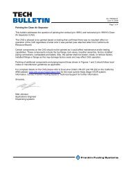
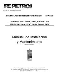
OverviewThe <strong>TSP</strong>-<strong>ULS</strong> is a <strong>Standard</strong> sensor that is used to detectthe presence of a liquid in the normally dry Class 1, Division1, Group D Hazardous Areas of: sumps, dispenser-pans,and interstitial areas of double-wall steel storage tanks.The sensor is supplied with electrical connectors, 25 feet ofcable, and a cord-grip fitting (see diagrams). The <strong>TSP</strong>-<strong>ULS</strong>uses magnetic-float/reed-switch technology (the sensormust be suspended vertically (See Figure 1) so the floatcan rise freely with the level of a liquid).When the float rises more than 1/2 of an inch, themagnetically sensitive reed switch will open (see internalfloat in Figure 1). An open circuit is recognized as an alarmconditionat the intrinsically safe (I.S) leak detection circuitsof the FFS (<strong>Franklin</strong> <strong>Fueling</strong> <strong>Systems</strong>) ATG console.Coloredmarkingpen/tapeInstall Height =Measured height+1.5 inch (38.1 mm)allowance for<strong>TSP</strong>-K12 height(Wht)(Blk)For installation in double-walled steel tanks, theinstall height is measured from the top of the riserto the bottom of the interstitial space in the tankTypical <strong>Sensor</strong> InputInterface (Channel N):3.62(Wht)In(92 mm) C NC(Blk)Gnd0.52(13.2 mm)1.48(37.6 mm)MagneticReed float switchopens when floatmoves up 0.52 inch(13.2 mm)Figure 1: <strong>TSP</strong>-<strong>ULS</strong> DimensionsSuspend <strong>Sensor</strong> VeritcallyMaterials Required• Optional – <strong>TSP</strong>-DB1 Epoxy Seal kit for no-strip electricalconnectors – recommended for sites: within flood zones,high groundwater tables, with poor drainage, or whenjunction boxes are not used.• 1/2 or 3/4 inch NPT (National Pipe Thread, tapered),Rigid Metal Conduit (RMC) or nonmetallic (PVC) conduitif allowed by local codes.• EYS Seal fittings and Epoxy to fill the fitting afteroperational testing is completed.• Weatherproof junction Box, gasket, and cover, plus a3/4 to 1/2 inch NPT reducing bushing if 1/2 inch RMC isused – see the ATG Installation Guide for recommendedelectrical Junction Boxes.• Wire: THHN, TFFN or THWN, 18 AWG, White & Black,or Alpha Cable # 58411, 0.114 O.D. – 1,500 feet (457meters) max. length. Alpha cable #58411 must be usewith nonmettalic conduit.• Slip joint pliers to seat the no-strip, self-sealing wireconnectors – connectors are supplied with the sensor.• UL Classified Thread Sealant or pipe dope.• *<strong>TSP</strong>-KI2 Riser Cap for 2-inch riser pipes, includes apre-installed 1/2 inch NPT compression gland (cord grip)fitting. Other riser caps are available for different riserpipe sizes – consult your factory rep.• * Riser pipe – 2 inch diameter (OD), threaded at one end(NPT-14) with all rough edges removed / deburred fromthe inner edges.* = Needed for installation in UST interstitial areas (Figure 2)Installation Sequence1. Install Riser Pipe, Manhole.2. Install conduit, EYS fittings, and weatherproofjunction box.3. Shut off power.ELECTRICAL DANGER Avoid electricalshock hazards: ensure all powergoing to the ATG console is turned off,tagged, and locked-out at the powerpanel before doing any maintenance orinstallation work at the ATG console.4. Interstitial installation – see Figure 1 & 2, measurethe INSTALL HEIGHT needed and add 1.5 inches= total height. Mark the total height on the sensorcable as shown in Figure 1, pull the cable throughthe <strong>TSP</strong>-KI2 Riser Cap and cord-grip until the markshows at the top of the cord grip fitting. Tighten thefitting and lower the sensor into the interstitial areaof the tank as shown in Figure 2.Install height(as measured)Double-wallsteel tankCover for14 inch (35.56 cm)Min. dia. manholeManhole<strong>TSP</strong>-KI2 riser cap(with cord grip - compression fitting)Concrete slabper NFPA 30Clean fill material(Gravel typical)WeatherproofJunction boxCompressionfitting (Cord grip)Eys seal Fitting1/2 or 3/4 inch conduit2 inch riser pipeInterstitial area (dry)<strong>TSP</strong>-<strong>ULS</strong><strong>Sensor</strong>Figure 2: Installation in Double-Walled Steel Tanks5. Pull the sensor cable through the cord grip fitting atthe junction box (also see Figure 3 for installationwithin a sump) and tighten all remaining cord-gripfittings. Trim wire / cables to a 6 or 8 inch (15 or20 cm) service-loop, and splice the sensor andconsole cable/wires together as shown in Figure 4.2
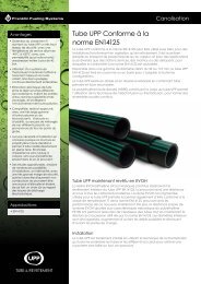
1/2 or 3/4 inchrigid metalconduitto ATGconsolesump/dispenser pan and coverWeatherproofjunction boxeys (epoxyfilled)ysealfitting<strong>TSP</strong>-<strong>ULS</strong>Figure 3: Installation in Sumps / Dispenser Pans6. Power up Console for next step.7. Test sensor (verify that an alarm is produced at ATGconsole), if it does produce an alarm, seal EYS sealfittings and electrical connectors with epoxy.8. Turn off power again if other devices are to beinstalled (Repeat Step 3).9. Reinstall all safety covers and guards, junctionbox gasket and covers – use pipe-dope to seal allfitting threads.10. Install the manhole cover.11. Record the location where the sensor wasinstalled on the chart on the last page of theseinstructions. This information will be needed whenprogramming the ATG.12. Turn on power and program the ATG – Ref: allrelating to <strong>Sensor</strong>s in the Setup / ProgrammingGuide manual.General Installation Notes* Steel double-walled tanks are equipped with a pipethat allows direct access to the bottom of the interstitial(annular) space. When installing a riser pipe in a steeltank, codes may require a non-conductive isolationbushing be installed between the tank and riser pipe.WarningIt is the installer’s responsibility tocomply with all applicable federal, stateand local codes. Failure to do so maycreate an Environmental Hazard.* Fill the bottom of the manhole with crushed stone tofacilitate drainage when the <strong>TSP</strong>-<strong>ULS</strong> is installed in theinterstitial space of a steel tank. Do not cover the top of theriser with fill material, it must remain accessible for serviceand for sensor installation.Plan your conduit routing. Dig trenches as necessary toinstall rigid threaded conduit (RMC) from each manholejunction box to the Intrinsically Safe (I.S.) knockouts at theATG console. The conduit may enter the manhole eitherfrom its bottom or through its side. A junction box insideof the building as a pull box to combine several sensorcables. If this is done, then only one I.S. conduit knockoutwill be used.Conduits must have EYS seal fittingsWarning installed in accordance with NFPA70 (National Electric Code) and NFPA30A (Automotive and Marine ServiceStation Code). Failure to seal conduitsin accordance with NFPA 30A, andNFPA 70 could allow flammable vaporsto travel through the conduit in theATG console. An explosion couldresult causing serious injury, propertyloss, or death.You must install a weatherproof, electrical junctionbox inside each manhole. The junction box should beinstalled high on the manhole wall to prevent it from beingsubmerged during heavy rains.CautionElectrical WiringSENSOR 1SENSOR NPWR(RED)IN(WHT)GND(BLK)PWR(RED)IN(WHT)GND(BLK)Note: ThePWR (red)terminal isnot used with2-wire sensorsSeal all threaded fittings and conduitthreads to produce a weatherproof sealduring installation/maintenance.2 wires/cable from consoleJ-boxFrom 2-wire sensorIN(WHT) GND(BLK)2-conductor cable from sensorInsert the unstripped wires fullyinto the self-sealing, no-stripelectrical connector.Use slip-joint pliers and seatthe black portion to make agood electrical connectionFigure 4: <strong>TSP</strong>-<strong>ULS</strong> WiringReference the ATG Installation Manual and see Figure 4(above) for <strong>TSP</strong>-<strong>ULS</strong> sensor wiring details. The two-wire<strong>TSP</strong>-<strong>ULS</strong> sensor does not have a red (power) conductor,therefore, the PWR (RED) interface terminal at the consoleis not used. When a 3-conductor Alpha cable is used, thered conductor can be clipped or taped back on both ends.Testing the <strong>TSP</strong>-<strong>ULS</strong>Testing this device is a matter of rotating the sensor 180degrees with the bottom up, to cause an alarm at the ATGconsole. Test the sensor for proper operation on a yearlybasis, or more frequently per local code.3
Record <strong>Sensor</strong> Location<strong>Sensor</strong>Channel # / Notes©2011 FFS 000-1346 Rev F