Painting the Clean Air Separator - Franklin Fueling Systems
Painting the Clean Air Separator - Franklin Fueling Systems
Painting the Clean Air Separator - Franklin Fueling Systems
You also want an ePaper? Increase the reach of your titles
YUMPU automatically turns print PDFs into web optimized ePapers that Google loves.
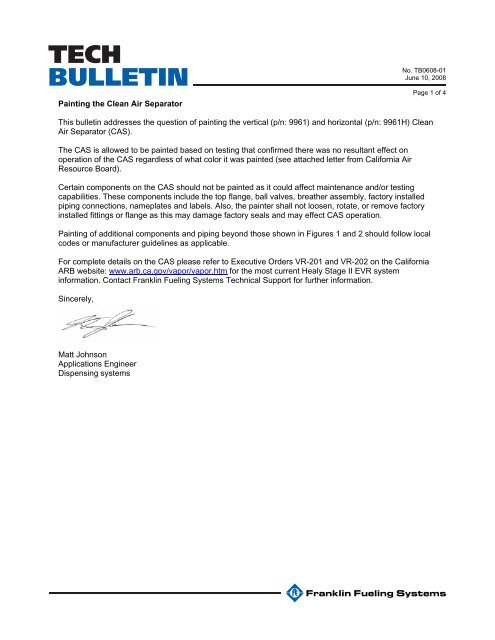
TECHBULLETIN<strong>Painting</strong> <strong>the</strong> <strong>Clean</strong> <strong>Air</strong> <strong>Separator</strong>No. TB0608-01June 10, 2008Page 1 of 4This bulletin addresses <strong>the</strong> question of painting <strong>the</strong> vertical (p/n: 9961) and horizontal (p/n: 9961H) <strong>Clean</strong><strong>Air</strong> <strong>Separator</strong> (CAS).The CAS is allowed to be painted based on testing that confirmed <strong>the</strong>re was no resultant effect onoperation of <strong>the</strong> CAS regardless of what color it was painted (see attached letter from California <strong>Air</strong>Resource Board).Certain components on <strong>the</strong> CAS should not be painted as it could affect maintenance and/or testingcapabilities. These components include <strong>the</strong> top flange, ball valves, brea<strong>the</strong>r assembly, factory installedpiping connections, nameplates and labels. Also, <strong>the</strong> painter shall not loosen, rotate, or remove factoryinstalled fittings or flange as this may damage factory seals and may effect CAS operation.<strong>Painting</strong> of additional components and piping beyond those shown in Figures 1 and 2 should follow localcodes or manufacturer guidelines as applicable.For complete details on <strong>the</strong> CAS please refer to Executive Orders VR-201 and VR-202 on <strong>the</strong> CaliforniaARB website: www.arb.ca.gov/vapor/vapor.htm for <strong>the</strong> most current Healy Stage II EVR systeminformation. Contact <strong>Franklin</strong> <strong>Fueling</strong> <strong>Systems</strong> Technical Support for fur<strong>the</strong>r information.Sincerely,Matt JohnsonApplications EngineerDispensing systems
TECHBULLETINNo. TB0608-01June 10. 2008Page 2<strong>Air</strong> Brea<strong>the</strong>r AssemblyTo Vent StackConnection(See CAS IOM forfur<strong>the</strong>r details)Nameplate andDataplateF PlugTop Flange andFactory InstalledFittingsB and CValvesA ValveE PlugD ValveFigure 1. Horizontal <strong>Clean</strong> <strong>Air</strong> <strong>Separator</strong> in Normal Operation(Items in Red Cannot Be Painted)
TECHBULLETINNo. TB0608-01June 10. 2008Page 3<strong>Air</strong> Brea<strong>the</strong>r AssemblyTo Vent Stack Connection(See CAS IOM for fur<strong>the</strong>r details)F PlugA ValveTop Flange andFactory InstalledFittingsB and CValvesD ValveE PlugNameplate andDataplateFigure 2. Vertical <strong>Clean</strong> <strong>Air</strong> <strong>Separator</strong> in Normal Operation(Items in Red Cannot Be Painted)
TECHBULLETINNo. TB0608-01June 10. 2008Page 4


