HeidelSat Ground Station for GENSO Network - SRH Hochschule ...
HeidelSat Ground Station for GENSO Network - SRH Hochschule ...
HeidelSat Ground Station for GENSO Network - SRH Hochschule ...

Create successful ePaper yourself
Turn your PDF publications into a flip-book with our unique Google optimized e-Paper software.
<strong>HeidelSat</strong> <strong>Ground</strong> <strong>Station</strong> <strong>for</strong> <strong>GENSO</strong> <strong>Network</strong><br />
Achim Gottscheber<br />
School of Engineering and Architecture<br />
<strong>SRH</strong> University of Applied Sciences Heidelberg<br />
Heidelberg, Germany<br />
achim.gottscheber@fh-heidelberg.de<br />
Abstract—First test results with the <strong>GENSO</strong> network are shown<br />
in this paper. It also describes the architecture of the <strong>HeidelSat</strong><br />
ground station, that is connected to the <strong>GENSO</strong> network.<br />
Keywords: <strong>GENSO</strong>, ground station, amateur radio<br />
frequencies, CubeSat<br />
I.INTRODUCTION<br />
The International Telecommunication Union (ITU)[1] is an<br />
agency of the United Nations which regulates in<strong>for</strong>mation and<br />
communication technology issues and coordinates the shared<br />
global use of the radio spectrum. Amateur Radio participation<br />
[2] in space research and communication is restricted to<br />
certain frequencies. The usage of these frequencies is free of<br />
charge, however, the operator of such frequencies needs to<br />
have an amateur radio license. An amateur radio satellite<br />
frequency allocation is done by the International Radio<br />
Amateur Union (IARU)[3].<br />
In 1999, a so called CubeSat[4] standard <strong>for</strong> pico satellite was<br />
initiated by Cali<strong>for</strong>nia Polytechnic State University and<br />
Stan<strong>for</strong>d University. It is recommended that such CubeSats<br />
should be no longer in space that 25 years.<br />
There<strong>for</strong>e, only low earth orbits (LEO) [5] are of interest in<br />
this respect. The time a Satellites needs to travel in an<br />
LEO,around the earth is about 90 minutes, and it can be<br />
continuously seen by a ground station <strong>for</strong> about 10 minutes or<br />
less in one circle around the earth.<br />
In order to have more often contact to a CubeSat in LEO, it is<br />
desired to have a network of many ground stations that are<br />
distributed around the earth in order to increase the average<br />
reception time per day <strong>for</strong> CubeSats.<br />
This was the reason to initiate a so-called <strong>GENSO</strong>[6] network<br />
of ground stations in 2006, that can interact via a software<br />
standard. A <strong>GENSO</strong> ground station is currently designed <strong>for</strong><br />
the 70cm and 2m amateur radio frequency band. However, it<br />
is planned to extend this also to other frequency bands, e.g.<br />
13cm band.<br />
II.HEIDELSAT GROUND STATION<br />
In 2006, a ground station <strong>for</strong> amateur radio frequencies (2m,<br />
70cm, 23cm, 13cm) was started to be build, see picture 1.<br />
Its name is <strong>HeidelSat</strong> and its call-sign is DN1FHH. The<br />
ground station has three antennas, i.e. a parabolic antenna with<br />
a diameter of 3,65m and two cross-yagi antennas. The<br />
parabolic antenna has a multi feed <strong>for</strong> the 13cm, 23cm and<br />
70cm band. The cross-yagi antennas are <strong>for</strong> the 70cm and 2m<br />
band. So far, only the 2m and 70cm cross-yagi antennas are<br />
Mathieu Chadelas<br />
Opto-Electronic and Hyper-Frequencies<br />
University of Montpellier 2<br />
Montpellier, France<br />
cyrain800@hotmail.com<br />
used <strong>for</strong> the <strong>GENSO</strong> network. The parabolic antenna is used<br />
to directly communicate with satellites using amateur radio<br />
frequencies.<br />
Picture 1 : <strong>HeidelSat</strong> ground station<br />
II.1 MATHEMATICAL COORDINATES FOR THE MOVEMENT OF<br />
THE ANTENNAS<br />
Elevation and azimuth are measured with a rotary encoder<br />
sensor to get the coordinates of the antennas, compare<br />
picture 2.<br />
1
Picture 2 : Coordinate system <strong>for</strong> elevation and azimuth<br />
It is possible to move the antenna manually or via a satellite<br />
tracking program or switch to predefined positions like the<br />
parking position or maintenance positions. There are two<br />
devices between the computer and the two rotors <strong>for</strong><br />
controlling the position of the antennas.<br />
1) A unit counter[7]<br />
2) A control unit<br />
II. 2 HARDWARE FOR CONTROLLING THE ANTENNAS<br />
The unit counter, in picture 3, and the control unit, in picture<br />
4, are described in this section. A unit counter is used as a<br />
sensor to set the position of the antennas. It has the function of<br />
a dual counter and a rate meter.<br />
Picture 3 : Unit counter<br />
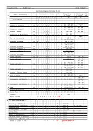
There are three rows on the left of the display shown in picture<br />
3. In row one, there is letter A. In row two, there is letter B. In<br />
row three, there is letter C. Each letter represent on counter.<br />
Letter «A» is dedicated to the azimuth and letter «B» to the<br />
elevation. The third counter is not used. Each counter needs an<br />
upper and lower coordinate limit. The maximum precision is<br />
0.5 degree. The counter communicates via RS232, having<br />
9600baud.<br />
A Control unit has been build to be able to switch<br />
between four different operating modes.<br />
Picture 4 : The control unit<br />
17<br />
In the first mode, signals arrive from an analog remote control.<br />
The second mode is <strong>for</strong> computer control, the third one is <strong>for</strong><br />
parking position, and the fourth <strong>for</strong> five different maintenance<br />
operations.<br />
The parking position is necessary <strong>for</strong> stormy weather<br />
conditions.<br />
II.3 LIGHTNING PROTECTION<br />
To protect the ground station from lightning strokes, the<br />
ground station is using three coaxial fuses. They are specified<br />
<strong>for</strong> a certain bandwidth and impedance. This protection has<br />
been implemented to increase the safety of the ground station.<br />
In addition, four interconnected ground rods are placed near<br />
by the antennas.<br />
The primary purpose of the external ground rods system is to<br />
disperse as much of the lightning energy as possible into the<br />
earth be<strong>for</strong>e it might follow the feed line into the ground<br />
station. The ground rods are visible in picture 1.<br />
II.4 GROUND STATION SOFTWARE<br />
A) SATELLITE RECEPTION SOFTWARE<br />
Ham Radio Deluxe (HRD) is a CAT control program<br />
providing computer control <strong>for</strong> commonly used transceivers<br />
and receivers. HRD also includes mapping, satellite tracking<br />
and the digital mode program Digital Master 780 (DM780).<br />
The Sat Track program adds satellite tracking capabilities to<br />
the Ham Radio Deluxe suite of programs. Its key features<br />
include:<br />
- Providing in<strong>for</strong>mation about when satellites will be within<br />
range.<br />
- Controlling the transceivers, setting frequencies and<br />
compensating <strong>for</strong> doppler shift.<br />
- Controlling the rotators so that the antennas can track 17<br />
satellites.<br />
Picture 5 : HAM Radio Deluxe<br />
Figure 3.4.1 HAM Radio Deluxe<br />
HRD, shown in picture 5, is used to configure the transceiver<br />
(ICOM IC-910H) <strong>for</strong> <strong>HeidelSat</strong> <strong>Ground</strong> <strong>Station</strong>, in respect to<br />
At <strong>HeidelSat</strong> <strong>Ground</strong> <strong>Station</strong>, we use HRD to configure our transceiver (Icom 910H) to<br />
<strong>GENSO</strong>.<br />
be able to communicate with other ground stations with the use of <strong>HeidelSat</strong> call signal<br />
(DN1FHH).<br />
MixW, shown in picture 6, is a multi mode, multi functional<br />
HRD is designed <strong>for</strong> Windows 2000 or higher (XP, Vista, 7), also Internet Explorer 6.0<br />
(or software. higher) is required. It supports The installation the modes of this : program CW, BPSK31, is quite simple QPSK31,<br />
but it requires at<br />
least some of minimum computer specifications which are:<br />
BPSK63 & 125, MFSK, RTTY, FSK31, Packet (HF and VHF<br />
including TCP/IP over AX25), Pactor RX/TX (TX requires<br />
� HRD: 500MHz CPU, 512MB RAM and 20MB of disk storage.<br />
� DM780: 1GHz CPU, 1024MB RAM and 50MB storage (or more if using SSTV).<br />
DM780 uses more resources than HRD when decoding many signals<br />
simultaneously.<br />
2
18<br />
19<br />
3.4.2<br />
MixW<br />
MixW is a multi mode multi functional software which can be used in many features.<br />
MixW supports many modes like CW, BPSK31, QPSK31, BPSK63 & 125, MFSK,<br />
RTTY, FSK31, Packet (HF and VHF including TCP/IP over AX25), Pactor RX/TX (TX<br />
TNC), Amtor (Sitor) TX/RX (No TNC needed), Hellschreiber,<br />
requires TNC), Amtor (Sitor) TX/RX (No TNC needed), Hellschreiber, FAX (RX only),<br />
FAX (RX only), SSTV, THROB, and MT63 [8][9]. In addition<br />
SSTV, THROB, and MT63. In addition to these built-in modes, new modes can be<br />
added to these to MixW built-in using a modes, facility called new "External modes mode can plugin be support". added to (Ref MixW 7)<br />
using a facility called "External mode plugin support". MixW<br />
MixW does does not not need require a TNC a TNC to operate. operate, The it only needs requirement a computer is that you with have a<br />
computer running Windows 9x, ME, NT, 2000, or XP operating system, and a<br />
compatible sound-card and one of the RigExpert USB<br />
compatible soundcard and one of the RigExpert USB interfaces. And it also allows using<br />
TCP/IP interfaces. connection It allows over AX.25 TCP/IP packet radio connection protocol. via AX.25 packet radio<br />
protocol.<br />
3.4.3<br />
PAXON<br />
Paxon is a software used in telemetry decoding that allows us to configure our TNC7<br />
Multi and choose the proper modulation technique <strong>for</strong> communications. There is a wide<br />
range of modulation techniques from which we can choose. For example, to use<br />
9600bps Picture FSK 6 : KISS/SMACK MixW Software mode, all we have to do is to switch the TNC7multi to<br />
position 9k6.<br />
Figure 3.4.2 MixW Software<br />
Paxon is a software used <strong>for</strong> telemetry decoding and allows to<br />
[<strong>SRH</strong> Paxon University is a very of Applied suitable Science Packet Heidelberg Radio | Ludwig-Guttmann-Strasse terminal program which 6, 69123 is used Heidelberg] specially <strong>for</strong><br />
Windows, by using this program it’s very easy to communicate with other ground<br />
station. configure our TNC7 Multi as well as to choose the proper<br />
modulation technique <strong>for</strong> communications, compare picture 7.<br />
At <strong>SRH</strong> Heidelberg we used this program with the need of TNC7 multi to communicate<br />
with Paxon our backup is a very station suitable in Mannhiem. Packet Radio terminal program which<br />
tuns on Windows XP.<br />
Picture 7 : Paxon Software<br />
Figure 3.4.3 Paxon Software<br />
B) EASYSKY<br />
EasySky [10] is an astronomy software that can also be used<br />
[<strong>SRH</strong> University of Applied Science Heidelberg | Ludwig-Guttmann-Strasse 6, 69123 Heidelberg]<br />
<strong>for</strong> satellite tracking. It has no connections to <strong>GENSO</strong>.<br />
However, it can be used to automatically operate <strong>HeidelSat</strong><br />
ground station via a PC, compare picture 8.<br />
19<br />
� EasySky<br />
!" #$%&'(')*(+%,'-./<br />
Be<strong>for</strong>e all manipulation, we have to guaranty that we are connect to the ERAC Telescope. In fact it is<br />
going to command the dish in function of the spacecraft or planet position.<br />
There are 3 softwares to organize this network correctly: We a<br />
� Authentication Servers (A US)<br />
This software is able to validate the<br />
identity of instances of the GSS and<br />
MCC, the following softwares. It allows<br />
maintaining up-to-date lists of the<br />
attributes and statuses of all <strong>GENSO</strong><br />
ground stations and spacecraft and<br />
Picture distributing 8 : EasySky these lists to instances of the<br />
GSS and MCC.<br />
C) To <strong>GENSO</strong> sum up, this software serve the<br />
project infrastructure with network data.<br />
The ground station network <strong>GENSO</strong> is using a ground station<br />
software standard which allows each ground station to<br />
communicate with non-local spacecraft and share the data<br />
with the spacecraft controllers via internet.<br />
Now we can follow the sun, we need just to click on the sun picture to display the command and<br />
characteristic window:<br />
The <strong>GENSO</strong> authentication server (AUS) connects ground<br />
stations and mission control centers via a hybrid peer-to-peer<br />
network. It controls the different <strong>GENSO</strong> ground stations and<br />
is located on one specific maintenance server in Europe.<br />
<strong>HeidelSat</strong> is<br />
�<br />
controlled<br />
!"#$%&'()*)+#%'(,"-,"'.!((/'<br />
by a <strong>Ground</strong> <strong>Station</strong> Server (GSS) and<br />
has also a Mission Control Client (MCC) as an interface<br />
between the <strong>GENSO</strong> network and satellite communications.<br />
The GSS allows us to automatically track and establish<br />
downlink connections with all compatible participating<br />
spacecraft, compare picture 9.<br />
Picture 9 : <strong>Ground</strong> station server (GSS)<br />
The MCC is shown in picture 10.<br />
Page 59 sur 98<br />
3<br />
T<br />
A<br />
G<br />
es<br />
p<br />
�<br />
T<br />
o<br />
al<br />
an<br />
b<br />
es<br />
T<br />
tr<br />
b<br />
sp
31<br />
Picture 10 : Mission control client (MCC)<br />
After finishing all the requirements and installations <strong>for</strong> the GENZO software Be<strong>for</strong>e in our all manipulation, we have to guaranty that we are connect to the ERAC Telescope. In<br />
ground station at <strong>SRH</strong> Heidelberg, we realized it works perfectly fine instead going of to the command the dish in function of the spacecraft or planet position.<br />
rotor, because it’s a handmade rotor and it doesn’t match with rotor of Genso network<br />
there<strong>for</strong>e, the rotor software now under constructing and it needs a couple weeks to be<br />
configured and works according to what we are expecting.<br />
[<strong>SRH</strong> University of Applied Science Heidelberg | Ludwig-Guttmann-Strasse 6, 69123 Heidelberg]<br />
Picture 11 : <strong>HeidelSat</strong> <strong>GENSO</strong> hardware schematic<br />
The physical installation, shown in picture 11, allows to<br />
integrate <strong>HeidelSat</strong> ground station into the <strong>GENSO</strong> network.<br />
D) DRIVER FOR THE HEIDELSAT ROTATOR<br />
In oder to integrate the <strong>HeidelSat</strong> ground station into the<br />
<strong>GENSO</strong> network, it was necessary to write a software driver<br />
<strong>for</strong> the rotors. All the other <strong>GENSO</strong> software could be<br />
directly used without modifications.<br />
III. CALIBRATION<br />
With the help of EasySky software, the exact position<br />
of the sun at a given time is exactly known. Like it is shown in<br />
picture 12 and 13, the parabolic antenna is manually pointed<br />
towards the sun, such that the sun shines into the center of a<br />
piece of paper.<br />
On this white paper a black cross indicates the center of the<br />
parabolic dish. When both (shadow and cross) are aligned, the<br />
EasySky software shows the coordinates of the antenna. The<br />
sensors attached to the rotators needs to be configured to the<br />
correct values.<br />
Picture 12 : Sun alignment calibration<br />
� EasySky<br />
Picture 13 : Sun alignment schematic<br />
������<br />
If the calibration is not perfect, it is possible to refine the<br />
position by using the «sun sound». An azimuth scanning<br />
shows where the sound is loudest. Then the same needs to be<br />
done <strong>for</strong> the elevation. The new coordinates results in a nearly<br />
perfect calibration which suffices <strong>for</strong> our application.<br />
IV. TRACKING EXAMPLE<br />
Now we can follow the sun, we need just to click on the sun picture to display the command<br />
characteristic window:<br />
IV.1 WITH EASYSKY<br />
Picture 14 : Tracking of satellites with EasySky<br />
4<br />
Page
31<br />
To track space objects, it’s necessary to enter updated Keppler<br />
data, e.g. from the NORAD data base into EasySky.<br />
The PC will then automatically send steering signals to the<br />
rotators and the transceiver can directly communicate with the<br />
the selected space object, compare picture 14.<br />
IV.2 WITH <strong>GENSO</strong><br />
Picture 15 : Tracking of satellites with <strong>GENSO</strong><br />
Similar to the EasySky software, the <strong>GENSO</strong> software can be<br />
used to track space objects. However, the <strong>GENSO</strong> mode<br />
allows also others mission control centers to use <strong>HeidelSat</strong><br />
ground station remotely.<br />
V. CONCLUSION<br />
The <strong>HeidelSat</strong> ground station[11] can be use <strong>for</strong> the<br />
<strong>GENSO</strong> network to communicate with satellites that use<br />
amateur radio frequencies in the 2m and the 70cm band. Also<br />
it can be used as an independent ground station in the 2m,<br />
70cm, 23cm and 13cm bands by using EasySky to track<br />
satellites.<br />
VI. REFERENCES<br />
[1] ITU Handbook on satellite communications,international<br />
After finishing all the requirements and installations <strong>for</strong> the GENZO software in our<br />
groundTelecommunications station at <strong>SRH</strong> Heidelberg, Union,Wiley,2002<br />
we realized it works perfectly fine instead of the<br />
rotor, because it’s a handmade rotor and it doesn’t match with rotor of Genso network<br />
[2] http://www.amsat.org<br />
there<strong>for</strong>e, the rotor software now under constructing and it needs a couple weeks to be<br />
configured [3] http://www.iaru.org/satellite<br />
and works according to what we are expecting.<br />
[4] http://www.<strong>GENSO</strong>.org/<br />
[5] Dennis Roddy, Satellite Commmunications, mcGraw-Hill<br />
professional,2006<br />
[<strong>SRH</strong> University of Applied Science Heidelberg | Ludwig-Guttmann-Strasse 6, 69123 Heidelberg]<br />
[6] http://www.genso.org<br />
[7] http://www.redlion.net/products/digitalandanalog/<br />
counters/batch/unit counter.html<br />
[8] Bruce Elbert, Introduction to Satellite Communication,<br />
Artech House Publishers; 3 edition, 2008<br />
[9] Mark J. Wilson, The ARRL Operating Manual For Radio<br />
Amateurs,Amer Radio Relay League, 2008<br />
[10] http://www.EasySky.de/eng/<br />
[11] http://www.fh-heidelberg.de/satellit<br />
31<br />
5