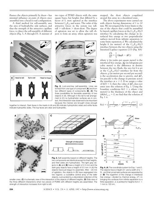
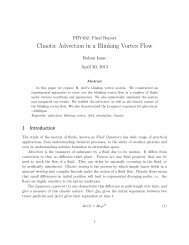
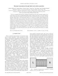
fluence the objects primarily by shear—hasm<strong>in</strong>imal <strong>in</strong>fluence on pairs <strong>of</strong> objects onceassembled <strong>in</strong>to a head-to-tail configuration.A third method for self-assembly usesthe area <strong>of</strong> hydrophobic side surfaces, andthus the strength <strong>of</strong> the attractive capillaryforce, to direct the self-assembly <strong>of</strong> differentobjects (Fig. 3, A through D). A mixture <strong>of</strong>two types <strong>of</strong> PDMS objects with the samesquare bases, but heights that differed by afactor <strong>of</strong> 5, were agitated at the <strong>in</strong>terfacebetween C 10 F 18 and water. <strong>The</strong> order <strong>of</strong> theattractive forces <strong>in</strong> the system was talltall tall-short short-short. <strong>The</strong> degree<strong>of</strong> agitation was set to allow the tall objectsto form an array; when agitation wasFig. 2. Lock-and-key self-assembly. L<strong>in</strong>es areformed from one type <strong>of</strong> component (A) and fromtwo different types <strong>of</strong> components (B). (C) <strong>The</strong>three possibilities for favorable assembly <strong>of</strong> twoobjects <strong>in</strong> (A). Although <strong>in</strong> the tail-to-tail arrangement<strong>in</strong> (C) no hydrophobic surfaces are <strong>in</strong> contact,this <strong>in</strong>teraction was observed to be importantbecause the menisci are brought close enoughtogether to <strong>in</strong>teract. Dark faces <strong>in</strong> the <strong>in</strong>sets <strong>in</strong> (A) and (B) <strong>in</strong>dicate hydrophobic sides and white faces<strong>in</strong>dicate hydrophilic sides. <strong>The</strong> top faces are clear and hydrophilic.stopped, the short objects coagulatedaround this array <strong>in</strong> a dis<strong>ordered</strong> state.<strong>The</strong> above experiments were carried outwith objects hav<strong>in</strong>g dimensions <strong>of</strong> 1 to 10mm. We <strong>in</strong>vestigated the lower limits to thesize <strong>of</strong> the objects that could be assembledby lateral capillary forces at the C 10 F 18 -H 2 O<strong>in</strong>terface by calculat<strong>in</strong>g the change <strong>in</strong> <strong>in</strong>terfacialfree energy as two perpendicularsurfaces moved from <strong>in</strong>f<strong>in</strong>ite separation tosome f<strong>in</strong>ite separation, d. We calculated theheight h (<strong>in</strong> meters) <strong>of</strong> the C 10 F 18 -H 2 O<strong>in</strong>terface between the two objects us<strong>in</strong>g thel<strong>in</strong>earized Laplace equation (13) (Fig. 4A) 2 hx 2 1 gh P 0 (1)where (<strong>in</strong> joules per square meter) is the<strong>in</strong>terfacial free energy, (<strong>in</strong> kilograms percubic meter) is the difference <strong>in</strong> densitybetween the two fluids, the zero for h is setat the C 10 F 18 -H 2 O <strong>in</strong>terface far from theobjects, g (<strong>in</strong> meters per second per second)is the acceleration due to gravity, and P 0(<strong>in</strong> pascals) is the change <strong>in</strong> pressure acrossthe <strong>in</strong>terface at x 0. If we assign a value<strong>of</strong> h(0) 0, then the value <strong>of</strong> P 0 does notenter <strong>in</strong>to the solution <strong>of</strong> Eq. 1. Us<strong>in</strong>g theboundary conditions h(r) t, where t (<strong>in</strong>meters) is the thickness <strong>of</strong> the object and(h/x) x0 0, we f<strong>in</strong>d that the solution <strong>of</strong>Eq.1is2hxt ex/xc d/2xc e x/xc)1e d/xc e d/2xc (2) eFig. 3. <strong>Self</strong>-assembly based on different heights. <strong>The</strong>two components are identical except for their heights,and their sides are hydrophobic. <strong>The</strong> light gray objects<strong>in</strong> (A) and (B) have a height <strong>of</strong> 2.5 mm and thedark gray objects have a height <strong>of</strong> 0.5 mm. In (A) theobjects have just begun to assemble. After 20 m<strong>in</strong><strong>of</strong> agitation, the objects <strong>in</strong> (B) have segregated <strong>in</strong>totwo regions: a crystall<strong>in</strong>e central array <strong>of</strong> the tallerobjects, surrounded by a dis<strong>ordered</strong> collection <strong>of</strong> thesmaller ones. (C) A schematic view <strong>of</strong> the <strong>in</strong>teraction <strong>of</strong> the objects <strong>of</strong> different heights. (D) Side view <strong>of</strong>the three different <strong>in</strong>teractions when two pieces <strong>of</strong> PDMS with different heights are assembled. <strong>The</strong>strength <strong>of</strong> <strong>in</strong>teraction <strong>in</strong>creases from right to left.Fig. 4. (A) <strong>The</strong> coord<strong>in</strong>ate system for Eqs. 1 and 2.<strong>The</strong> objects have a height <strong>of</strong> t and a width <strong>of</strong> w 5t , and their proximate surfaces are separated byd. (B) <strong>The</strong> logarithm <strong>of</strong> the change <strong>in</strong> <strong>in</strong>terfacialfree energy—divided by thermal energy, kT—<strong>in</strong>br<strong>in</strong>g<strong>in</strong>g two surfaces from <strong>in</strong>f<strong>in</strong>ite separation to af<strong>in</strong>ite separation, d, is plotted for heights from t 1 mm to 100 nm.234SCIENCE VOL. 276 11 APRIL 1997 http://www.sciencemag.org
REPORTSwhere we have made the replacement x c (/g) 1/2 . For <strong>in</strong>f<strong>in</strong>ite d the capillary surfaceis given by a simple exponential decaywith h(x) e (x/x c) .To estimate the change <strong>in</strong> <strong>in</strong>terfacialenergy as a function <strong>of</strong> distance, we calculatedthe difference <strong>in</strong> the arc length (<strong>in</strong>meters), def<strong>in</strong>ed by h(x) for two surfacesseparated by d and two surfaces separated byan <strong>in</strong>f<strong>in</strong>ite distance; the change <strong>in</strong> arclength was then multiplied by the width <strong>of</strong>the object w (<strong>in</strong> meters), and the <strong>in</strong>terfacialfree energy to yield the change <strong>in</strong> <strong>in</strong>terfacialfree energy (14). As a model system, weassigned a length to the perpendicular surfaceequal to five times the height. Thismodel gave a change <strong>in</strong> <strong>in</strong>terfacial free energy,W, <strong>of</strong> W 5t. From thechange <strong>in</strong> <strong>in</strong>terfacial free energy for heightsfrom t 1 mm to 100 nm (Fig. 4B), weconclude that the energetics for self-assemblyare favorable for objects with t as smallas 100 nm. For the two-dimensional selfassembly<strong>of</strong> spheres, the radius at whichW/kT 1 (where kT is the thermal energy)has been calculated to be on the order<strong>of</strong> 1 to 10 m (15, 16). <strong>Self</strong>-assemblydriven by capillary forces between conformalsurfaces should therefore make possiblethe assembly <strong>of</strong> much smaller objectsthan would be possible with spheres; theability to control the shapes and <strong>in</strong>terfacialproperties <strong>of</strong> these objects makes itpossible to design the geometries <strong>of</strong> theresult<strong>in</strong>g arrays.Four factors contribute to the success <strong>of</strong>this strategy for the directed self-assembly <strong>of</strong>small objects. First, the aggregates are energeticallymore stable than the <strong>in</strong>dividualdissociated objects or dis<strong>ordered</strong> aggregates.Second, formation <strong>of</strong> the aggregates is reversiblewhen the system is agitated: formationand dissociation <strong>of</strong> the aggregates compete.<strong>The</strong> aggregates are therefore able toreach the energetically most stable form.Third, the hydrophobic sides are attractedto one another over large distances (abouttwo to three times the dimension <strong>of</strong> theheight), lead<strong>in</strong>g to relatively rapid assembly.Fourth, even when two hydrophobicsides are <strong>in</strong> close proximity, they can movelaterally from side to side, lubricated by the<strong>in</strong>terven<strong>in</strong>g film <strong>of</strong> C 10F 18, and can thusmaximize the amount <strong>of</strong> hydrophobic area<strong>in</strong> contact.REFERENCES AND NOTES___________________________1. <strong>The</strong>re are few methods for assembl<strong>in</strong>g arrays <strong>of</strong>small objects. See (2, 4, 5); J. K. Tu, J. J. Talghader,M. A. Hadley, J. S. Smith, Electron. Lett. 31, 1448(1995); A. Ashk<strong>in</strong> and J. M. Dziedzic, Science 235,1517 (1987); K. Svoboda and S. M. Block, Annu.Rev. Biophys. Biomol. Struct. 23, 247 (1994).2. A. W. Simpson and P. H. Hodk<strong>in</strong>son, Nature 237,320 (1972).3. S. T. Schober, J. Friedrich, A. Altmann, J. Appl.Phys. 71, 2206 (1992).4. M. Yamaki, J. Higo, K. Nagayama, Langmuir 11,2975 (1995).5. P. A. Kralchevsky and K. Nagayama, ibid. 10, 23(1994).6. PDMS is easy to fabricate and its solid-liquid <strong>in</strong>terfacialfree energy can be readily controlled by oxidation tomake the surfaces hydrophilic or hydrophobic. Weplaced the PDMS structure <strong>in</strong>to a plasma cleaner for 5m<strong>in</strong> under O 2at a pressure <strong>of</strong> 0.20 torr to oxidize thePDMS. <strong>The</strong> oxidation <strong>of</strong> PDMS is believed to result <strong>in</strong>a surface that comprises SiOH groups. <strong>The</strong> contactangle <strong>of</strong> water on oxidized PDMS is less than 15°.7. M. J. Owen, J. Coat<strong>in</strong>gs Technol. 53, 49 (1981).8. W. A. Zisman, <strong>in</strong> Symposium on Adhesion and Cohesion,P. Weiss, Ed. (Elsevier, New York, 1962), p.176.9. D. W. Fakes, M. C. Davies, A. Browns, J. M. Newton,Surf. Interface Anal. 13, 233 (1988).10. <strong>The</strong> perfluorodecal<strong>in</strong> wet the unoxidized PDMS andformed a meniscus; the water wet the higher energysurface <strong>of</strong> oxidized PDMS. <strong>The</strong> capillary forces act<strong>in</strong>gat the oxidized surfaces were very weakly attractivecompared to those <strong>of</strong> the hydrophobic surfaces,because the PDMS (density 1.05 g ml 1 ) does nots<strong>in</strong>k far enough <strong>in</strong>to the perfluorodecal<strong>in</strong> (density 1.91 g ml 1 ) to generate a meniscus with significantcurvature at the hydrophilic <strong>in</strong>terfaces. Other fluor<strong>in</strong>atedalkanes with properties similar to those <strong>of</strong> perfluorodecal<strong>in</strong>were used with equal success.11. C. D. Dashk<strong>in</strong>, P. A. Kralchevsky, W. N. Paunov, H.Yoshimura, K. Nagayama, Langmuir 12, 641 (1996).12. <strong>The</strong> evidence that a th<strong>in</strong> layer <strong>of</strong> C 10F 18rema<strong>in</strong>edbetween the PDMS solids at their closest contact is<strong>in</strong>direct: When two flat pieces <strong>of</strong> PDMS come <strong>in</strong>contact <strong>in</strong> water with no C 10F 18present, they stick toeach other strongly, and this process is effectivelyirreversible. If we add C 10F 18to the water after thePDMS solids have come <strong>in</strong>to contact, they rema<strong>in</strong>stuck to one another.13. H. T. Davis, Statistical Mechanics <strong>of</strong> Phases, Interfacesand Th<strong>in</strong> Films: Advances <strong>in</strong> Interfacial Eng<strong>in</strong>eer<strong>in</strong>g( VCH, New York, 1996).14. In perform<strong>in</strong>g these calculations, we used values <strong>of</strong> 0.05 J m 2 and 900 kg m 3 for the C 10F 18-H 2O <strong>in</strong>terface.15. P. A. Kralchevsky, V. N. Paunov, N. D. Denkov, I. B.Ivanov, K. Nagayama, J. Colloid Interface Sci. 155,420 (1993).16. V. N. Paunov, P. A. Kralchevsky, N. D. Denkov, K.Nagayama, ibid. 157, 100 (1993).17. We thank M. Mammen for helpful comments andsuggestions. Funded by NSF grant CHE-9122331,the Office <strong>of</strong> Naval Research, and the Defense AdvancedResearch Projects Agency. N.B. was supportedby a predoctoral fellowship from the Department<strong>of</strong> Defense. A.T. thanks the Deutsche Forschungsgeme<strong>in</strong>schaftfor a research grant.4 November 1996; accepted 24 February 1997Permo-Triassic Boundary Superanoxia andStratified Superocean: Records fromLost Deep SeaYukio IsozakiPelagic cherts <strong>of</strong> Japan and British Columbia, Canada, recorded a long-term and worldwidedeep-sea anoxic (oxygen-depleted) event across the Permo-Triassic (or Paleozoicand Mesozoic) boundary (251 2 million years ago). <strong>The</strong> symmetry <strong>in</strong> lithostratigraphyand redox condition <strong>of</strong> the boundary sections suggest that the superocean Panthalassabecame totally stratified for nearly 20 million years across the boundary. <strong>The</strong> tim<strong>in</strong>g <strong>of</strong>onset, climax, and term<strong>in</strong>ation <strong>of</strong> the oceanic stratification correspond to global bioticevents <strong>in</strong>clud<strong>in</strong>g the end-Guadalupian decl<strong>in</strong>e, the end-Permian ext<strong>in</strong>ction, and mid-Triassic recovery.<strong>The</strong> greatest mass ext<strong>in</strong>ction <strong>in</strong> the Phanerozoicoccurred at the tim<strong>in</strong>g <strong>of</strong> thePermo-Triassic (P-T) boundary; many hypothesesfor the ext<strong>in</strong>ction have focused onchanges <strong>in</strong> the ocean, <strong>in</strong>clud<strong>in</strong>g development<strong>of</strong> overturn <strong>of</strong> an anoxic ocean (1, 2).One problem has been that most records <strong>of</strong>the boundary are <strong>in</strong> shallow-water sedimentaryrocks that formed around the supercont<strong>in</strong>entPangea. Recently, however, P-Tboundary sections were discovered <strong>in</strong> deepseacherts that crop out extensively <strong>in</strong> theJurassic accretionary complex <strong>in</strong> southwestJapan (3, 4). <strong>The</strong> cherts represent ancientpelagic sediments primarily deposited <strong>in</strong> amid-oceanic deep sea <strong>of</strong> the superoceanPanthalassa and accreted onto the SouthCh<strong>in</strong>a (Yangtze) cont<strong>in</strong>ental marg<strong>in</strong> <strong>in</strong> theDepartment <strong>of</strong> Earth and Planetary Sciences, Tokyo Institute<strong>of</strong> Technology, O-okayama, Meguro, Tokyo 152,Japan. E-mail: yisozaki@geo.titech.ac.jpMiddle Jurassic (5). <strong>The</strong> Panthalassa superoceanoccupied nearly 70% <strong>of</strong> Earth’s surface<strong>in</strong> the Late Permian (6). Rocks nearthe P-T boundary are reduced, and arethought to have been deposited <strong>in</strong> an anoxicenvironment (3, 4, 7, 8). I refer tothese rocks as the P-T boundary unit(PTBU; Fig. 1). Across the PTBU, Paleozoicradiolarians (planktonic protozoans)are completely replaced by dist<strong>in</strong>ct Mesozoictypes. Similar rocks have also recentlybeen found <strong>in</strong> British Columbia, Canada. Iused the sections from Japan and BritishColumbia to evaluate Panthalassa oceandynamics across the P-T boundary.In the Japanese sections, Early to earlyLate Permian and Middle to Late Triassiccherts are composed ma<strong>in</strong>ly <strong>of</strong> siliceous radiolariantests (95% by weight) and aremostly brick red <strong>in</strong> color. X-ray diffractionand 57 Fe Mössbauer spectroscopy demon-http://www.sciencemag.org SCIENCE VOL. 276 11 APRIL 1997 235