Anritsu MG3700A: Vector Signal Generator - elsinco
Anritsu MG3700A: Vector Signal Generator - elsinco
Anritsu MG3700A: Vector Signal Generator - elsinco

Create successful ePaper yourself
Turn your PDF publications into a flip-book with our unique Google optimized e-Paper software.
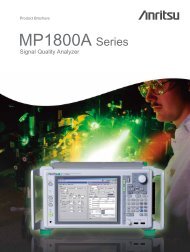
Product Brochure<strong>MG3700A</strong><strong>Vector</strong> <strong>Signal</strong> <strong>Generator</strong>250 kHz to 3 GHz, 250 kHz to 6 GHz (Option)Excellent Eco Product
For measurement of wireless communicationsevolving into “high speed, large capacity, andwide band”.Wireless communications, which are now evolvingrapidly, are moving into high speed, largecapacity, and wide band.And next-generation wireless communicationsare addressing a new communication format thatcombines cellular phones with the access ofwireless LANs.<strong>MG3700A</strong> is a vector signal generator based on a160 MHz arbitrary waveform generator that includesthe features of “Wide vector modulation bandwidth”and a “Large capacity baseband memory.”Furthermore, <strong>MG3700A</strong> supports digital modulationof signals for various wireless communicationsystems, enabling you to evaluate general mobilecommunications, such as cellular phones andwireless LANs.<strong>Anritsu</strong>’s waveform generation softwareIQproducer can create waveform patterns andtransmit them to <strong>MG3700A</strong> via 100BASE-TXEthernet. Furthermore, IQ sample data files (in ASCIIformat) programmed by using general EDA(Electronic Design Automation) tools such asMATLAB ® can also be converted to waveformpatterns for <strong>MG3700A</strong>.And a custom-made waveform pattern file can begenerated arbitrarily.∗MATLAB is a registered trademark of The Math works, Inc.2
Baseband-arbitrary waveform generator.Sample rate: 20 kHz to 160 MHzARB memory size:256 Msamples/ch (Standard)512 Msamples/ch (Option)Frequency Range 6 GHzModulation Bandwidth:Large capacity HDD:40 GB.BER analyzerInput bit rate: 1 kbps to 20 Mbps. (Standard)100 bps to 120 Mbps. (Option)■ Performance and functions•Frequency Range 250 kHz to 6 GHz250 kHz to 3 GHz (Standard)250 kHz to 6 GHz (Option)•Wide vector modulation bandwidth120 MHz (Internal base band generator)150 MHz (External IQ input)•High level accuracy±0.5 dB (Absolute level accuracy)±0.2 dB typical (Linearity)•High speed waveform transmission by 100BASE-TX Ethernet.• 40 GByte hard disk is built in.• Large capacity baseband memory.1 GBytes = 256 Msamples/channel (Standard)2 GBytes = 512 Msamples/channel (Option)•Waveform addition functionTwo signals, such as wanted signal +interfering signal or wanted signal +AWGN, can be added and outputted.•Standard 20 Mbps BERT analyzer is built in.1 kbps to 20 Mbps (Standard)100 bps to 120 Mbps (Option)■ Support for various communication systemsStandard ∗1•Waveform Patterns:Arbitrary waveform patterns corresponding to the followingcommunication systems are included as standard.Features:W-CDMA/HSDPA, GSM/EDGE, CDMA2000 ® 1X/1xEV-DOWireless LAN (IEEE802.11a/b/g), PDC, PHS, AWGN,Bluetooth ®∗2 , GPS, Digital Broadcast (ISDB-T1 segment, BS,CS, CATV)• Optional Waveform Patterns:Arbitrary waveform patterns corresponding to the followingcommunication systems are provided as options:TD-SCDMAPublic Radio System (RCR STD-39, ARIB STD-T61/T79/T86)•Waveform generation software: IQproducer(Software license is optional)IQproducer is PC application software with a graphical userinterface for changing parameters and generating waveformpatterns that comply with various communication systems:W-CDMA, AWGNHSDPA/HSUPA ∗3 , TDMA ∗3 , CDMA2000 1xEV-DO ∗3 ,Multi-carrier ∗3 , Mobile WiMAX ∗3 , DVB-T/H ∗33∗1 Please refer to the catalog “MX370x series software” for details.∗2 The Bluetooth word mark and logos are owned by the Bluetooth SIG, Inc.and any use of such marks by <strong>Anritsu</strong> is under license. Other trademarksand trade names are those of their respective owners.∗3 The license installed in mainframe is necessary.∗CDMA2000 ® is a registered trademark of the Telecommunications IndustryAssociation (TIA-USA).
Easy-to-use panel designMain PWR (Power supply switch)Switches power On/Off. When power is supplied, the left lamp(Main PWR) turns green. Furthermore, the right lamp (On)turns orange at the time of Power On.Hard Disk (Hard disk lamp)The light turns on when the mainframe built-in HDD is beingaccessed.Panel Lock (Panel lock key)All key operations except the power supply switch andLocal are disabled. A lamp (red) lights in panel lock state.Display Off/On (Display Off/On key)Switches the display On/Off. A lamp (red) lights up when thedisplay is off.Local (Local key)Disables remote control by GPIB and Ethernet and allowslocal control only.Remote (Remote lamp)Turns on in when remote control is Being carried out by GPIBand Ethernet.Preset (Preset key)Setup a parameter to its initial state.Function Keys (Soft function keys)Chooses and executes the menu displayed on the extremeright of the display. When there are two or more menuscreens, additional menu pages are viewed via the “More”key.Function (Main function key)Changes modes for setting up the main functions of thisequipment:Frequency: Frequency setting modeLevel: Output level setting modeBaseband: Baseband setting modeUtility: Utility setting modeCursor/Edit (Cursor/Editing key)Used for item selection or entering a numerical setting. “Set”finalizes the selection and “Cancel” cancels it. The rotary knobis disabled when “Knob Hold” is pressed and its lamp is on.CF Card (Compact Flash card slot)A slot for the memory card used for installing waveformpatterns or software, and for saving screen displays.Numeric KeypadShift: Press this key first (its lamp lights) to enable theblue-letter functions on the panel above the keys.Numeric keys: It is used in the case of a numerical setting.Unit keys: Indicates the unit after a numerical input.RF Output (RF <strong>Signal</strong> Output)Output: Changes the RF signal output on/off state. Its lamplights when the RF signal output is enabled.MOD On/Off: Turns modulation on/off when RF signal outputis enabled. Its lamp lights when the RF signal is beingmodulated.RF Output: The connector for RF signal output. (N-J, 50 Ω)Modulation Input (External IQ modulation input connector)I/Q input signal when an external baseband signal performsvector modulation.(BNC-J, 50 Ω, Input voltage range ±5 Vpeak)Control Input (Control input connector)Start trigger, frame trigger and pattern trigger input signal.(BNC-J, TTL, Polarity reversal of rising/falling edges is possible.)Ethernet (100BASE-TX LAN connector)A connector for linking to a PC when performing remotecontrol or transmitting a waveform pattern. When using thisconnector, the two Ethernet connectors on the back panelare short-circuited by the attached LAN straight cable.(8-pin Cat-5 modular jack)Display (Display)8.4 inch, 640 x 480 dots, Color TFT LCD.The screen display can be saved on the HDD or CF card asa picture file in color or gray scale.4
Buffered Output (Reference frequency signal output connector)Output for this equipment’s 10 MHz reference frequencysignal. This signal is for synchronizing with other equipment.This signal is outputted whenever the mainframe power ison. (BNC-J, TTL, DC coupling)Ref Input (Reference frequency signal input connector)External reference frequency signal (10 MHz or 5 MHz)input. It is for signals with higher accuracy than thereference frequency inside this equipment, or whensynchronizing with the reference signal of other equipment.(BNC-J, ≥0.7 Vp-p/50 Ω AC coupling)AUX Input/Output (AUX I/O connector)Marker signal output. (BNC-J 3 port, TTL)Baseband Ref Clock Input(Baseband reference clock input connector)Input for the clock signal that becomes the reference for theD/A sampling clock. (BNC-J, ≥0.7 Vp-p/50 Ω ACcoupling, Input frequency range 20 kHz to 160 MHz)Ext Pulse Mod Input (External Pulse Mod signal inputconnector)External input signal for controlling the signal output on/off ina pulse modulation function. (BNC-J, 50 Ω, Input voltagerange 0 to 5 V, Threshold= about 1 V)IQ Output (IQ output connector)Differential output of the baseband signal (I/Q) generated inthe arbitrary waveform generation function (D-Sub 15-J, 50Ω). If the optional accessory “IQ output conversion adapter(option)” is used, it is convertible to BNC.Fan (Fan for air cooling)An air cooling fan for suppressing the internaltemperature rise of this equipment.Protective earth terminalThis terminal should be grounded when a grounded powercord cannot be used.Line Input (AC power input)AC input for the power supply.GPIB (GPIB connector)Used when performing remote control by GPIB.Ext. ALC Input (External ALC connector)External DC voltage input for controlling the output level.(+3 to –8 dB)(BNC-J, 600 Ω, Input voltage range ±5 V)BER Input (BER input connector)Used for BER measurements:Enable: BER measurement gate signal input.Clock: Input for clock signal synchronized with the data.Data: Data input. (BNC-J, TTL)Junction ConnectorWhen using the Ethernet connector on the front panel, thisJunction connector and the Ethernet connector above mustbe short-circuited by the attached LAN straight cable.(8-pin Cat-5 modular jack)EthernetEthernet connector for linking to a PC when performingremote control or transmitting a waveform pattern.This connector can be used instead of the Ethernetconnector on the front panel.(8-pin Cat-5 modular jack)5
Basic performance■ Covers frequency range 250 kHz to 6 GHz.Choose either 250 kHz to 3 GHz (standard) or 250 kHz to 6 GHz(option) for the frequency range. A 6 GHz upper frequency isrequired for the WLAN 5 GHz band frequency andnext-generation communication system support.■ High level accuracy:■ Wide vector modulation bandwidth.120 MHz (Using internal baseband signal generator)150 MHz (Using External IQ input)A wider “RF modulation bandwidth” of 120 MHz is achievedwhen internal baseband signal generation is used.Furthermore, 150 MHz vector modulation bandwidth is supportedfor up to 6 GHz frequency when the External IQ input is used.Excellent level accuracy assures a high level of overallmeasurement accuracy.•Absolute level accuracy:±0.5 dB typ (≥–120 dBm 25 MHz≤ fc ≤3 GHz, E-ATT ∗ )±0.8 dB typ (≥–120 dBm 3 GHz< fc ≤6 GHz, E-ATT ∗ )±0.5 dB typ (≥–120 dBm 25 MHz≤ fc ≤3 GHz, M-ATT ∗ )±0.8 dB typ (≥–100 dBm 3 GHz< fc ≤6 GHz, M-ATT ∗ )∗ E-ATT: Electronic attenuator, M-ATT: Mechanical attenuatorFrequency characteristicLinearity<strong>Vector</strong> Modulation Bandwidth (Using external IQ input)6
SSB phase noise (25 MHz≤f≤3 GHz)(CW, Continuous mode: OFF, Frequency changing speed: Normal)SSB phase noise (3 GHz
Useful standard functions■ Waveform combining function<strong>MG3700A</strong> contains two built-in arbitrary waveform memories, and these two memories can each choose one waveform pattern,respectively. <strong>MG3700A</strong> can output the signal of either one of the memories, and can also combine and output both signals simultaneously.When measuring receiver characteristics, such as “ACS: Adjacent Channel Selectivity” or “Blocking characteristics”, the“Wanted <strong>Signal</strong>+Interfere <strong>Signal</strong>” and “Wanted <strong>Signal</strong>+AWGN” can be outputted by one <strong>MG3700A</strong>. Since digital processing is used foradjustment and S/N, the level ratio accuracy is excellent.Wanted <strong>Signal</strong> + AWGN screenOutput waveform screenWanted <strong>Signal</strong> + Interfering <strong>Signal</strong> screen[Combination file]The Combination function makes the work of waveform additioneven easier. The Combination function uses a file with variousSteps required without combination functionOutput waveform screenparameters such as the pattern selection for the two outputwaveforms, the output level ratio, and the offset frequency.Simply selecting this file performs these settings automatically.Effect of combination function• Processing required waveform + interference waveform• Set required waveform in memory A.• Set interference waveform in memory B.• Set level of required waveform.• Set level of interference waveform.• Set offset frequency of required and interferencewaveforms.Auto-setting by just selecting the combination file.The combinations file is generated with IQproducer.(Please use the appended file the combinations file of “ControlCH + data” of W-CDMA.)• Processing W-CDMA control CH + Data CH• Set Control CH in memory A• Set Data CH in memory B.• Set level of Control CH.• Set level of Data CH.8
■ Sequence ModeSteps required without sequence mode• Create a single waveform pattern combining the requiredwaveform pattern type and times, and save it in memory.• Create a new waveform pattern whenever the repetition timechanges.Sequence Mode is a Combination function application that savesoperating parameters, such as the waveform pattern repetitiontimes, waveform pattern switching, and output level settings, to afile. Simply selecting this file performs these operations automatically.This is very convenient when investigating state transitionsin response to received signals, such as during connection procedures.Inside of memoryWaveform patternA A A B B C CA wave pattern is outputted as it is.Inside of memoryEffect of sequence modeWaveform patternCombination fileThe required waveform pattern and combination file are savedin memory. Moreover, an external trigger can be used to repeateach waveform pattern any number of times.⇒ Makes efficient use of memory⇒ Permits investigation of response status transitions⇒ Enables manual sequence controlABC+A x 3B x 2C x 2Output waveform patternA A A B B C C■ Standard 20 Mbps BER is built in.A BER analyzer is a standard feature, allowing BERmeasurement of the receiving characteristic to be performedeasily. Input bit rate: 1 kbps to 20 MbpsMeasurable BER: 0 to 1%There is also a BER option for measurement from100 bps to 120 Mbps (see the next page).This can be used by connecting the signal demodulated by theDUT to the Enable/Clock/Data BNC connectors on the backpanel of the equipment.In addition, a log of up to 100 BER measurement results canbe saved. The log file contains test information including measurementtime and date, error rate, bit count, terminationcause, and measurement mode.Connector of the rear panelPlease note “Time” setting is in the count mode of the general builtinBER measurement equipment, but it is not in the high-speedBER measurement function of <strong>MG3700A</strong>-031/131.BER measurement screenCount modeStandard BER<strong>MG3700A</strong>-031/131measurement function High speed BER test functionTime✓DataBit/Data ✓ ✓Error✓9
Options■ Hardware options:Model: <strong>MG3700A</strong>-001Name: Rubidium Reference OscillatorThis provides a 10 MHz reference signal VCO. Frequencystability is improved compared to the standard VCO.Frequency: 10 MHzAging rate: ±1 x 10 –10 /MonthTemperature stability: ±1 x 10 –9 (0 to +50˚C)Model: <strong>MG3700A</strong>-002Name: Mechanical AttenuatorThe standard electronic attenuator is changed to amechanical attenuator. This improves the maximumpermissible output level and the distortion characteristic.Settable range: –140 to +19 dBmAccuracy range (CW): –140 to +10 dBmModel: <strong>MG3700A</strong>-011Name: Upper Frequency 6 GHzThe upper frequency range is extended to 6 GHz from 3GHz. Frequency range after extension: 250 kHz to 6 GHzModel: <strong>MG3700A</strong>-021Name: ARB Memory Upgrade 512MsampleThe memory capacity of the ARB unit for arbitrarywaveform generation is extended to “256 Msample/channelx 2” from “128 Msample/channel x 2.”Model: <strong>MG3700A</strong>-031Name: High speed BER Test functionThis option upgrades the standard built-in BER measurementfunctions as follows:- Enhancing of measurement data rate:100 bps to 120 Mbps- Addition of SyncLoss count function- Addition of discontinuous PN data measurement function- Addition of user pattern measurement function■ Comparison between standard BER measurementfunction and option BER measurement functionOn/Off function of AutoResyncCountMode ∗1TimeDataBit/DataErrorMeasurement data rateupper limitSyncLoss count functionMeasurement ofdiscontinuous PN dataUser patternmeasurementBER Measurement Variation Caused by Auto Resync On/OffThe figure below shows one example of a BER measurement that indicatesSyncLoss. Actual results depend on the specific communication system anddata rate, and will not necessarily match the measurement values below.BER[%]1.E-001.E-011.E-021.E-031.E-04Standard BERmeasurement function(ver2.02 or later)✓✓✓20Mbps–––1.6E-14.5E-3<strong>MG3700A</strong>-031/131High speed BERTest function✓+ Thresholdadjustment✓✓120Mbps✓✓✓It is possible to perform continuous measurementof even high error rates by changing themeasurement conditions to match the error rates."Auto Resync=OFF" is required for manufacturinginspection of some communications systemsrequiring reception sensitivity with BER=1%, andfor R&D applications that evaluate receptionsensitivity limits.This can be used for WLAN and next-generationhigh-speed communications systems.This can be used for continuous measurementeven when synchronization loss occurs.When the size of continuous data such ISDB-TPN23 exceeds the <strong>MG3700A</strong> memory capacity,measurement can be performed by reducing thememory requirements using discontinuous PNdata.This can be used for measuring fixed patternssuch as those specified by WiMAX.The maximum value of BER that becomes Sync LossAuto Resync=OffAuto Resync=OnCase usedMeasurement range can be set.∗1: The measurement count of standard BER measurement function (ver2.02 former) wasable to be set by "Time" and "Number of bits". The High-speed BER Test functionoption is lost of the setting of "Time", and can set "Number of bits" and "Number oferror bits".1.E-05-14 -10 -6 -2 2 6Input level ( dBµV)Example of measurement systemRS-232CPDCtest unitData/ClockPDCmobile phoneRF10
■ Software options: Waveform pattern∗:Waveform pattern options provide waveform data that meet therequirements of various communication systems and can beused by the <strong>MG3700A</strong> built-in arbitrary waveform generator.Waveform patterns are downloaded to the <strong>MG3700A</strong> for use.Model: MX370001AName: TD-SCDMA Waveform PatternWaveform patterns for transmission/reception test of the3GPP 1.28 Mcps TDD Option (TD-SCDMA) are provided.Model: MX370002AName: Public Radio System Waveform PatternWaveform patterns that comply with RCR STD-39 andARIB STD-T61/T79/T86∗ .Waveform patterns, such as Uplink/Downlink and thecontinuation waves PN9/PN15, are provided.RCR STD-39: narrow band digital-communications systemARIB STD-T61: narrow band digital-communications systemARIB STD-T79: Public digital-communications systemARIB STD-T86: Public digital-communications systemModel: MX370104AName: Multi-carrier IQproducerThe MX370104A Multi-carrier IQproducer is GUI-drivenPC application software for creating multi-carrier waveformpatterns corresponding to the modulation and tone signalsof various communication systems.There is also a function for converting two waveform patternswith different sampling rates to a waveform patternwith one sampling rate, as well as a function for creating awaveform pattern with W-CDMA Downlink multi-carrier andclipping.Model: MX370105AName: Mobile WiMAX IQproducerA part of the parameter of MAC management messages ofDL/UL-MAP and DCD/UCD, etc. can be set.The generated waveform pattern can be used for a part ∗ of8.4.13 Receiver Requirement of IEEE802.16e.[∗: Function test (HO etc.) that cannot be done only by the signal generatoris excluded.]■ Software options: IQproducer License∗:IQproducer can be installed in a PC to evaluate its operationbefore purchase. In order to download generated waveformpatterns to the <strong>MG3700A</strong> and to output signals, the followingIQproducer license options are required:Model: MX370101AName: HSDPA/HSUPA IQproducerParameters can be changed and the desired waveformpatterns can be generated for HSDPA Uplink/Downlinkand HSUPA E-DPDCH/EDPCCH.Model: MX370106AName: DVB-T/H IQproducerThe parameters for the ETSI EN 300 744 V1.5.1 (2004-11)Physical Layer specification are set and a waveform patternis generated. A video file waveform pattern is generated byreading the user's MPEG-2 TS file. The generated waveformpattern can be used for the receiver sensitivity test usingBER measurement and for the final operation check usingthe video.∗: Please refer to the catalog “MX370x series software” for details.Model: MX370102AName: TDMA IQproducerParameters can be changed and the desired waveformpatterns can be generated for TDMA system signals. Theparameters that can be set include Modulation, Frame,Slot, Data, and Filter.Model: MX370103AName: CDMA2000 1xEV-DO IQproducerParameters can be changed and the desired waveformpatterns can be generated for CDMA2000 1xEV-DOForward/Reverse signals.11
Useful functions of the waveformgeneration software IQproducer■ Functions of IQproducer:IQproducer is PC application software, that can generatewaveform patterns and transmit them to <strong>MG3700A</strong>.IQproducer is provided with <strong>MG3700A</strong> as a standard feature,and has the following four functions.• Parameter setting function• Simulation function• File generation function• Data transfer functionAfter trying the waveform pattern generation function with theIQproducer System function, in order to actually use awaveform pattern in <strong>MG3700A</strong> the license (option)corresponding to each system is required.• Simulation function: Simulation• Parameter setting function: SystemThe IQproducer System function has a graphical userinterface corresponding to each communication system so youcan set up parameters easily. A file with the resulting parametersettings can also be saved and recalled.This function displays a generated waveform as a CCDF or FFTgraph on the PC. It is useful for checking/reviewing waveformsbefore transfer to the <strong>MG3700A</strong>.• CCDF (Complimentary Cumulative Distribution Function)Graph:Up to 8 types of generated waveform can be read and displayedas CCDF graphs.CCDF graphHSDPA IQproducer setting screen sample• IQproducer Operating Environment• FFT (Fast Fourier Transform) graph:Up to 4 types of generated waveform patterns can be read andthe transformed results displayed as FFT graphs.CPUMemoryHDDDisplayOSPentium ® III,1 GHz or more≥512 Mbytes≥10 GBytes1024 x 768 pixels or greaterWindows ® 2000 Professional, Windows ® XPPentium ® is a registered trademark of Intel Corporation in theUnited States and other countries.Windows/Windows2000/WindowsXP is a registered trademark ofMicrosoft Corporation in the United States and other countries.FFT graph12
• File generation function: File Gen• Data convert function: ConvertThe IQ sample data files in ASCII format programmed bygeneral signal generation software (such as MATLAB) can alsobe converted to waveform patterns for <strong>MG3700A</strong>.This enhances the convenience of <strong>MG3700A</strong> forresearch/development simulation use, since custom-madewaveform pattern files can be freely generated.• AWGN (Additive White Gaussian Noise) waveform generationfunctionThis function establishes the sampling rate and bandwidth,allowing any AWGN waveform pattern to be created.In addition, when the first combined waveform pattern (Wanted<strong>Signal</strong>) is selected, the Wanted <strong>Signal</strong> bandwidth and samplingrate are set automatically.The resulting AWGN waveform pattern and an existing waveformpattern can be combined, which is useful for base-stationdynamic-range measurements.The main set parameter(1) Wanted <strong>Signal</strong> BW: Wanted <strong>Signal</strong> band-widthSetting range: 0.0010 to 120.0000 MHz(2) AWGN BW (B)/Wanted <strong>Signal</strong> BW (A):Magnification of AWGN to Wanted <strong>Signal</strong>Setting range: 1.0, 1.5, 2.0, 2.5(3) Sampling Rate:Setting range: 0.0200 to 160.0000 MHzIt makes it to the same value as the Wanted <strong>Signal</strong>.(4) AWGN BW (B): Bandwidth of AWGNIt calculates automatically from (1) and (2), and it has thefollowing limitation.Limit range: 0.001 to 20.000 MHz and “Sampling rate/2” orless than, 20.001 to 120.000 MHz and “Sampling rate” orless thanConvert screenAWGN screen13
• Data transfer function: Transfer and SettingA PC and the <strong>MG3700A</strong> can be connected via 100BASE-TXEthernet, and data such as a waveform pattern generated byIQproducer, a picture file, or a firmware upgrade file can betransmitted. Since waveform patterns can also be transmitted ina single procedure when multiple <strong>MG3700A</strong>s are connected viaa LAN, operating time is reduced.Moreover, waveform patterns on the <strong>MG3700A</strong> hard disk canbe saved by remote control in the arbitrary waveform memory,and a waveform pattern can also be chosen to output.• Combination File generation functionThe Combination File Edit function is one of the Transfer &Setting Edit functions. Each Combination File contains the followingparameters, so these settings are performed automaticallyjust by selecting the Combination File:• Waveform pattern• Repetition times• Interference waveform pattern (Memory B)• Frequency offset (at addition of Memory A and Memory B)• Level ratio (C/N at addition of Memory A and Memory B, andrelative level between elements for Memory A only)Setting the Wanted <strong>Signal</strong> waveform and interference waveformseparately in the two memories makes it easy to measurereceiver characteristics.Moreover, receive signal status transitions can also be verifiedwith a sequence by setting the switching and repetition timesfor multiple waveform patterns.Transfer & Setting screenTransfer & Setting screenCombination File Edit screen14
Measurement sampling■ Supports receiving characteristic evaluation for the base station and terminals of various mobile communications:Since <strong>MG3700A</strong> supports waveform patterns that meet the requirements of mobile communications systems and includes a built-inBER analyzer, it is the optimal equipment for receiving characteristic measurement. Moreover, the <strong>MG3700A</strong> waveform combiningfunction can combine two waveform patterns. A single <strong>MG3700A</strong> is thus able to output two signals, such as a “wanted signal +interfering signal” and “wanted signal + AWGN (Additive White Gaussian Noise)”.<strong>MG3700A</strong> <strong>Vector</strong> <strong>Signal</strong> <strong>Generator</strong>BER analyzer is built in.Wanted signalBER measurementDUTData,Clock,Enable∗Input bit rate: 1 kbps to 20 Mbps (Standard)100 bps to 120 Mbps (Option)• The receiving sensitivity test covers the measurement item specified by BER (Bit Error Rate).>>> Examples: W-CDMA, GSM, PHS, and PDC• Since the BER analyzer is built in as a standard feature, a receiver test can be carried out easily with a small footprint.<strong>MG3700A</strong> <strong>Vector</strong> <strong>Signal</strong> <strong>Generator</strong>wanted signal + interfering signalwanted signal + AWGNDUTThe waveform combine function is built in.Wanted <strong>Signal</strong> + Interfering screenOutput waveform screen• The receiving sensitivity test covers measurements using two signals, such as ACS (Adjacent Channel Selectivity) and the blockingcharacteristic.• The waveform combining function enables a single instrument to output a signal such as “wanted signal + interfering signal” and “wantedsignal + AWGN”.• Since S/N adjustment is carried out by digital processing, the level ratio accuracy is excellent.15
■ Supports receiving characteristic evaluation of dual system cellular phone-related equipment:In the cellular phone market where usage of dual systems such as “cellular phone+WLAN” is increasing, a signal source for variouscommunication systems is needed for receiving characteristic evaluation of a terminal/module/tuner. Since <strong>MG3700A</strong> supports thewaveform patterns of major communication systems and it excels in extendibility, it is the optimal signal generator for receivingcharacteristic evaluation of dual system equipment that will be developed in the near future.Moreover, it is important to determine that the receiving characteristic is not deteriorated by mutual interference of the new dualcommunication systems. In this case, the <strong>MG3700A</strong> can also be used to create an interfering signal.MT8820A Radio Communication AnalyzerWanted signal<strong>MG3700A</strong> <strong>Vector</strong> <strong>Signal</strong> <strong>Generator</strong>Teminator (MP752A)Combiner (MA1612A)DUTWanted signal/Interfering signal• A single <strong>MG3700A</strong> can output the wanted signal for receiving characteristic evaluation of various communication systems.• It can also be used as an interfering signal for evaluating deterioration of the receiving characteristic due to mutual interference.■ Supports the research and development of continuously evolving communication systemsBy using the IQproducer data conversion function, a custom-made waveform file can be freely generated with common EDA tools.For example, an IQ sample data file simulated by MATLAB is convertible to the waveform pattern file used by <strong>MG3700A</strong> with the“external data conversion function” of IQproducer. Thus, the MATLAB simulation result can be compared with an actualmeasurement result.PC MATLAB ®<strong>MG3700A</strong> <strong>Vector</strong> <strong>Signal</strong> <strong>Generator</strong><strong>Signal</strong> AnalyzerDUT16
Specifications• <strong>MG3700A</strong> mainframe ∗1FrequencyOutput levelRangeResolutionInternal reference oscillatorExternal reference inputBuffer outputSwitching timeFrequency setup and DisplaySettable rangeUnitResolutionAccuracy250 kHz to 3 GHz (standard), 250 kHz to 6 GHz (option)0.01 HzFrequency: 10 MHz, Aging rate: ±1 x 10 –8 /day, ±1 x 10 –7 /year, Temperature stability: ±2 x 10 –8 (0 to +50°C),Start-up characteristics (at 23°C):±5 x 10 –8 (After 5 min, compared to frequency after 24 h warm-up)With Rubidium Reference Oscillator OptionFrequency: 10 MHz, Aging rate: ±1 x 10 –10 /Month, Temperature stability: ±1 x 10 –9 (0 to +50°C),Start-up characteristics (at 23°C):±1 x 10 –9 (After 7 min, compared to frequency after 24 h warm-up)Frequency: 5 MHz/10 MHz (auto-switching), Operating range: ±1 ppm, Input level: ≥0.7 Vp-p/50 Ω(AC coupled), Connector: BNC-J (rear panel, Ref Input)Frequency: 10 MHz, Output level: TTL (DC coupled), Connector: BNC-J (rear panel, Buffered Output)Response time from final command to ±0.1 ∗ ppm of set frequency on GPIB.∗ (When the set frequency is 1 GHz or less, response time from final command to ±100 Hz)When Frequency changing speed = Normal:≤40 ms (When going by 3 GHz)≤15 ms (When the amount of frequency change is less than 1 GHz without going by 3 GHz)≤20 ms (When the amount of frequency change is 1 GHz or more without going by 3 GHz)When Frequency changing speed = Fast:≤40 ms (When going by 3 GHz)≤10 ms (When not going by 3 GHz)With Mechanical Attenuator OptionRegardless of frequency changing speed.:≤100 ms (When going by 3 GHz)≤80 ms (When not going by 3 GHz)Direct setup: The absolute value of frequency is set up and displayed.Setup by CH: CH is assigned to frequency. Separate CH tables can be assigned to two or moresystems (groups). Group names and CH numbers are set and displayed. Furthermore, thecorresponding frequency is displayed simultaneously.–140 to +13 dBm (At CW, accuracy range: –136 to +6 dBm)With Mechanical Attenuator Option–140 to +19 dBm (At CW, accuracy range: –136 to +10 dBm)∗:Please refer to “<strong>Vector</strong> modulation/In the case of vector modulation, the level error in comparisonwith CW” for level accuracy at vector modulation.Power: dBm,Voltage: dBµV (terminate voltage display), dBµV (open voltage display)0.01 dB (dBm, dBµV)at CW and 23°C ±5°C:Level (p) [dBm]Frequency (f) [Hz]250 k ≤f < 25 M 25 M ≤f ≤3 G 3 G < f ≤6 G ∗+3 < p ≤+6 ±0.5 dB–1 < p ≤+3 ±0.5 dB ±0.8 dB–120 ≤p ≤–1 ±0.5 dB typical ±0.5 dB ±0.8 dB–127 ≤p
Output level<strong>Signal</strong> purity<strong>Vector</strong> modulationLinearitySwitching timeVSWRSpecial setting modeContinuous modeEXT ALC modeOutput connectorMaximum reverse inputSpuriousHarmonicsNon harmonicPower supply relationEVMACLR (5 MHz offset)ACLR (10 MHz offset)In the case of vectormodulation, the level error incomparison with CW. ∗2Carrier leakImage rejectionExternal modulationRF spectrum invertat CW, –11 dBm and at 23°C ±5°C:±0.2 dB typical (at –120 to –11 dBm, 25 MHz ≤f ≤3 GHz)±0.3 dB typical (at –120 to –11 dBm, 3 GHz < f ≤6 GHz)With Mechanical Attenuator Optionat CW, –7 dBm and at 23°C ±5°C:± 0.2 dB typical (at –120 to –7 dBm, 25 MHz ≤f ≤3 GHz)± 0.3 dB typical (at –120 to –7 dBm, 3 GHz < f ≤6 GHz)Response time from final command to ± 0.1 dB of final level on GPIB.f < 25 MHz: ≤15 ms (Normal mode), ≤10 ms (Continuous mode)f ≥25 MHz: ≤10 ms (It is not based on the mode.)With Mechanical Attenuator Option≤80 ms (Normal mode), ≤10 ms (Continuous mode)at ≤–11 dBm output level: 1.3 (250 kHz ≤f ≤3 GHz), 1.55 (3 GHz < f ≤6 GHz)With Mechanical Attenuator Optionat ≤–7 dBm output level: 1.25 (250 kHz ≤f ≤3 GHz), 1.35 (3 GHz < f ≤6 GHz)Continuous mode and EXT ALC mode are the exclusive modes.Level adjustment is possible at 0.01 dB steps in the range of “+3/–10 dB”, without becomingOutput off on the basis of the conditions when shifting to continuous mode.Output level is changed according to the direct-current voltage inputted externally.Variable range: –8/+3 dB, Input impedance: 600 Ω (nominal),Connector: BNC-J (rear panel, Ext. ALC)50 Ω, N-J (front panel, RF Output)Reverse input power: 1 Wpeak (≥300 MHz), 0.25 Wpeak (
Pulse modulationInternal modulationExternal modulationOutput voltage rangeON/OFF ratio: >60 dB, Rise/fall time: 60 dB, Rise/Fall time:
Waveform memoryStart/Frame triggerPattern triggerMemory modeFunctionInput connectorStart triggerFrame triggerFunctionInput connectorFunctionInput connectorInput signalInput levelInput threshold levelDefined ModeSelection of a single waveform pattern to be used in either waveform memory A or B, selection ofwaveform patterns by a combination file that defines addition of multiple waveform patterns, and theaddition level ratio can be set at once in this mode.If a combination file that specifies two or more waveform patterns in waveform memory A is selected,the following sequence operations become enabled.• Selection of pattern switching mode (Auto/Manual)• Selection of pattern switching point (Frame end/Pattern end)• Switching of pattern by an external trigger signal (enabled when the pattern switching mode is Manual)• Restart of sequence• Maximum number of elements: 200• Minimum number of points per pattern: 1000Level ratio setting range: Two-signal level ratio
BER measurementfunction(Option:<strong>MG3700A</strong>-031,<strong>MG3700A</strong>-131)External interfaceFunctionConnectorInput signalInput levelInput threshold levelInput impedanceAdjustable range of input timingInput bit rateMeasurable patternsMeasurable BERMeasurable bit countMeasurable error bitAuto ResyncMeasurement modeDisplayGPIB100BASE-TX EtherMemory cardSizeBER can be measured for data strings converted to 1s and 0s following demodulation.Rear panel, BER Input, BNC-J connectorData, Clock, Enable (Polarity reversal is possible)0 to 5 V0.20 to 3.00 V (0.05 V step)50 Ω, High impedance–1 to 15 clock (Data/Enable is adjusted for input Clock.)100 bps to 120 MbpsPN 9, 11, 15, 20, 23, ALL0, ALL1, ALT(01 repetition)PN 9fix, 11fix, 15fix, 20fix, 23fix, UserDefine0 to 10% (Reference value. Changed by the condition of the communication system and the data rate.)1000 to 4294967295 (2 32 – 1) bit1 to 2147483647 (2 31 – 1) bitOn, Off (When On is set, it becomes SyncLoss by the error detecting condition of Threshold and themeasurement is stopped. When Off is set, the detection of SyncLoss is not performed.)Threshold setting range:[numerator/denominator] Choose from denominator = 500, 5000, 50000,numerator = 1 to denominator/2, (Default: 200/500)Single, Continuous, EndlessBitError, SyncLoss, ClockError, Enable Error, SyncLoss Count, Overflow Data Count, OverflowSyncLoss, Error Rate, Error CountTarget of control: The functions except a power supply switch, local key, and contrast keys arecontrollable etc.Interface: SH1, AH1, T6, L4, TE0, SR1, RL1, PP0, DC1, DT1, C0, E2Connector: GPIB (rear panel, GPIB)Function: Waveform pattern transfer and control.Connector: Modular jack [Cat.5] 8pin (front panel and rear panel, Ethernet)In order to use the Ethernet connector of a front panel, it is necessary to short-circuit twoEthernet connectors of a rear panel by a U link cable (standard accessory).Function: Waveform pattern, a memory parameter, software, and CH table can be saved or recalledto/from a Compact-Flash card.Connector: Slot (front panel, CF Card)8.4 inch, 640 x 480 dots, color TFT LCDDisplay On/Off setting Panel display On/OffScreen saveVoltageFrequencyA currently displayed screen can be saved to HDD/CF card as a BMP file.AC 100 to 120 V, 200 to 240 V (–15/+10%, 250 V MAX)47.5 to 63 HzPower Power consumption ≤200 VATemperature OperatingStorage+5 to +45°C–20 to +60°CDimensions and massEMC426 (W) x 177 (H) x 451 (D) mm, ≤15 kg (excluding option)EN61326: 1997/A2: 2001 (Class A), EN61000-3-2: 2000 (Class A),EN61326: 1997/A2: 2001 (Annex A)LVD EN61010-1: 2001 (Pollution Degree 2)∗1 The following conditions are applied unless otherwise specified.Common to CW mode and modulation mode. [Continuous mode: Off, External ALC: Off, Frequency switching speed: Normal, Pulse modulation: Off], Onlyduring modulation mode [Input level to DAC (RMS): Full scale 14 dB to full scale 17 dB, Sampling rate: >100 kHz, Memory mode: Except combining twowaveform, IQ Output: Off, After CAL execution, During internal modulation]∗2 At modulation mode, ALC: Off21
Composition guidesystem ∗1The <strong>MG3700A</strong> <strong>Vector</strong> <strong>Signal</strong> <strong>Generator</strong> includes a variety of general hardware and software as standard equipment. Therefore,optional equipment is not required. When the model name “<strong>MG3700A</strong>” is specified, it is supplied with the functions and performancemarked as “standard” in the following table.However, you may choose and combine the functions and performance marked as “option” in the following table in order to addhardware performance extensions and waveform pattern software.Classification Outline Standard Option NoteFrequency range250 kHz to 3 GHz ✓250 kHz to 6 GHz ✓ 6 GHz Frequency Extension OptionStandard ✓ Frequency: 10 MHz, Aging rate: ±1 x 10 –8 /day, ±1 x 10 –7 /yearReference oscillator Rubidium Reference✓Rubidium Reference Oscillator OptionOscillatorFrequency: 10 MHz, Aging rate: ±1 x 10 –10 /MonthElectron Attenuator✓AttenuatorMechanical Attenuator OptionMechanical Attenuator ✓ The electron attenuator mounted as standard is changed into mechanicalattenuator.1 GBytes =128 Msamples/channel x 2.256 Msamples/channel✓It can be used as a maximum of 256 Msamples/channel.MemoryARB Memory Upgrade 512 Msample Option2 GBytes =✓ 256 Msamples/channel x 2.512 Msamples/channelIt can be used as a maximum of 512 Msamples/channel.Base-band generator Internal/External ✓<strong>Vector</strong> modulation band-width (Internal): 120 MHz<strong>Vector</strong> modulation band-width (External): 150 MHz✓Input bit rate: 1 kbps to 20 MbpsMeasurable Patterns: PN 9/11/15/20/23, ALL0, ALL1, repetition of 0 and 1BER analyzerHigh speed BER Test function OptionInput bit rate: 100 bps to 120 Mbps✓Measurable Patterns: PN 9/11/15/20/23, ALL0, ALL1, repetition of 0 and 1PN9fix/11fix/15fix/20fix/23fix, UserDefineHard disk 40 GBytes ✓A non-volatile hard disk for saving various waveform patterns andparameters of <strong>MG3700A</strong>.W-CDMA✓GSM/EDGE✓CDMA2000 1X/1xEV-DO ✓W-LAN (IEEE802.11a/b/g) ✓PDC✓These waveform patterns are stored in the hard disk as standard.PHS✓License is not required in order to use these.Waveform patterns software ∗1 Bluetooth® ✓GPS✓Digital Broadcast (ISDB-T 1segment, BS, CS, CATV)✓AWGN✓TD-SCDMA ✓ The license is required. (Model: MX370001A)Public Radio System(ARIB STD-T61/T79/T86)✓ The license is required. (Model: MX370002A)HSDPA/HSUPA ✓ The license is required. (Model: MX370101A)Universal TDMA ✓ The license is required. (Model: MX370102A)IQproducerCDMA2000 1xEV-DO ✓ The license is required. (Model: MX370103A)License for each Multi-carrier ✓ The license is required. (Model: MX370104A)Mobile WiMAX ✓ The license is required. (Model: MX370105A)DVB-T/H ✓ The license is required. (Model: MX370106A)In accordance with the standards of various communication systems, theParameter setting function ✓ various parameters of a waveform pattern can be edited easily. Theparameter edit results are saved as a setting file, and can also be recalled.The setting file created by the system with the “parameter setting function”is converted to an <strong>MG3700A</strong> waveform pattern. When using the <strong>MG3700A</strong>IQproducer Data converter function ✓ generated waveform signal, the above “license for each system” is needed.(PC application software)Moreover, a setting file programmed by the C language or MATLAB canbe converted to a waveform pattern. In this case, a license is not required.Data transfer function✓Waveform patterns, display copy files, and update programs can betransmitted from a PC to <strong>MG3700A</strong> via Ethernet.Simulator function✓Allows a waveform to be checked on a PC by FFT and CCDF beforesending the waveform pattern to a mainframe.1 year ✓Warranty service2 years ✓ Standard 1 year + 1 year3 years ✓ Standard 1 year + 2 years5 years ✓ Standard 1 year + 4 years∗1: Please see the waveform pattern and IQproducer data sheet.22
Ordering InformationPlease specify model/order number, name, and quantity when ordering.Model/Order No. Name Remarks— Mainframe —<strong>MG3700A</strong> <strong>Vector</strong> <strong>Signal</strong> <strong>Generator</strong>— Standard accessories —J0017F Power Cord, 2.6 m: 1 pcJ1276 LAN Straight Cable: 1 pc 10 cm, For U link connection on Rear panelCompact Flash: 1 pc 64 MB or moreJ1254 Compact Flash Adapter: 1 pcZ0742 <strong>MG3700A</strong> CD-ROM: 1 pc Main frame operation manual, IQproducer operation manual, Standardwaveform operation manual, IQproducer software— Options —<strong>MG3700A</strong>-001 Rubidium Reference Oscillator Aging rate: ±1 x 10 –10 /Month<strong>MG3700A</strong>-002 Mechanical Attenuator Standard Electron Attenuator is changed into Mechanical Attenuator.<strong>MG3700A</strong>-011 Upper Frequency 6 GHz Standard “250 kHz to 3 GHz” is extended to “250 kHz to 6 GHz.”<strong>MG3700A</strong>-021 ARB Memory Upgrade 512 M Sample Standard “128 Msample/channel x 2” is extended to“256 Msample/channel x 2.”<strong>MG3700A</strong>-031 High Speed BER Test Function Standard “BER Test function” is extended.<strong>MG3700A</strong>-101 Rubidium Reference Oscillator Retrofit Retrofitted to the already-shipped mainframe.<strong>MG3700A</strong>-102 Mechanical Attenuator Retrofit Retrofitted to the already-shipped mainframe.<strong>MG3700A</strong>-103 Electronic Attenuator Retrofit Retrofitted to the already-shipped mainframe.<strong>MG3700A</strong>-111 Upper Frequency 6 GHz Retrofit Retrofitted to the already-shipped mainframe.<strong>MG3700A</strong>-121 ARB Memory Upgrade 512 M Sample Retrofit Retrofitted to the already-shipped mainframe.<strong>MG3700A</strong>-131 High Speed BER Test Function Retrofit Retrofitted to the already-shipped mainframe.— Maintenance service —<strong>MG3700A</strong>-ES210 Extended Warranty Service Two years<strong>MG3700A</strong>-ES310 Extended Warranty Service Three years<strong>MG3700A</strong>-ES510 Extended Warranty Service Five years— Softwares (Waveform pattern) —MX370001A TD-SCDMA Waveform PatternMX370002A Public Radio System Waveform Pattern RCR STD-39, ARIB STD-T61/T79/T86MX370101AMX370102AMX370103AMX370104AMX370105AMX370106A— Softwares (License Key for IQproducer system) —HSDPA/HSUPA IQproducerTDMA IQproducerCDMA2000 1xEV-DO IQproducerMulti-carrier IQproducerMobile WiMAX IQproducerDVB-T/H IQproducer— Optional accessories —Z0777 Standard Waveform Pattern Upgrade Kit (DVD 4 piece sets)W2495AE <strong>MG3700A</strong> Operation ManualW2496AE <strong>MG3700A</strong> IQproducer Operation ManualW2539AE <strong>MG3700A</strong> Standard Waveform Pattern Operation ManualW2533AE MX370001A TD-SCDMA Waveform Pattern Operation ManualW2503AE MX370101A HSDPA/HSUPA IQproducer Operation ManualW2504AE MX370102A TDMA IQproducer Operation ManualW2505AE MX370103A CDMA2000 1xEV-DO IQproducerOperation ManualW2633AE MX370104A Multi-carrier IQproducer Operation ManualW2734AE MX370105A Mobile WiMAX IQproducer Operation ManualW2798AE MX370106A DVB-T/H IQproducer Operation ManualG0141 HDD ASSY For Embedded HDD ExchangeK240B Power Divider (K connector) DC to 26.5 GHz, K-J, 50 Ω, 1 WmaxMA1612A Four-Port Junction Pad 5 MHz to 3 GHz, N-JMP752A Termination DC to 12.4 GHz, 50 Ω, N-PMA2512A Band Pass Filter For W-CDMA, pass band: 1.92 to 2.17 GHzJ0576B Coaxial Cord, 1.0 M N-P • 5D-2W • N-PJ0576D Coaxial Cord, 2.0 M N-P • 5D-2W • N-PJ0127A Coaxial Cord, 1.0 M BNC-P • RG-58A/U • BNC-PJ0127B Coaxial Cord, 2.0 M BNC-P • RG-58A/U • BNC-PJ0127C Coaxial Cord, 0.5 M BNC-P • RG-58A/U • BNC-PJ0322A Coaxial Cord, 0.5 M SMA-P • SMA-P, DC to 18 GHz, 50 ΩJ0322B Coaxial Cord, 1.0 M SMA-P • SMA-P, DC to 18 GHz, 50 ΩJ0322C Coaxial Cord, 1.5 M SMA-P • SMA-P, DC to 18 GHz, 50 ΩJ0322D Coaxial Cord, 2.0 M SMA-P • SMA-P, DC to 18 GHz, 50 Ω23
Model/Order No. Name RemarksJ1264 N-SMA Adapter N-P • SMA-JJ1261B Ethernet Cable (Shield Type) Straight, 3 mJ1261D Ethernet Cable (Shield Type) Cross, 3 mJ0008GPIB CABLE, 2.0 MJ1277 IQ Output Conversion Adapter D-SUB/BNCB0329CFront Cover for 1MW 4UB0331C Front Panel Handle Kit 2 pcs/setB0332 Joint Plate 4 pcs/setB0333CRack Mount KitB0334C Hardtype Carrying Case With front cover and a castersP0021Compact Flash 128 MBP0022Compact Flash 256 MBP0023Compact Flash 512 MBTypical (typ):Performance is not warranted. A large majority of all products meet typical performance.Nominal:Values are not warranted. They are included to facilitate the application of the product.Example:Performance is not warranted. Data are actually measured by randomly selected measuring instruments.Trademarks:• IQproducer is a registered trademark of <strong>Anritsu</strong> Corporation.• MATLAB is a registered trademark of The Math works, Inc.• CDMA2000 ® is a registered trademark of the Telecommunications Industry Association (TIA-USA).• The Bluetooth word mark and logos are owned by the Bluetooth SIG, Inc. and any use of such marks by <strong>Anritsu</strong> is under license.Other trademarks and trade names are those of their respective owners.• Pentium ® is a registered trademark of Intel Corporation in the United States and other countries.• Windows/Windows2000/WindowsXP is a registered trademark of Microsoft Corporation in the United States and other countries.• CompactFlash is a registered trademark of SanDisk Corporation in the United States and is licensed to CFA (Compact Flash Association).• All other trademarks are the property of their respective owners.Specifications are subject to change without notice.<strong>Anritsu</strong> Corporation5-1-1 Onna, Atsugi-shi, Kanagawa, 243-8555 JapanPhone: +81-46-223-1111Fax: +81-46-296-1264• U.S.A.<strong>Anritsu</strong> Company1155 East Collins Blvd., Richardson, TX 75081, U.S.A.Toll Free: 1-800-ANRITSU (267-4878)Phone: +1-972-644-1777Fax: +1-972-671-1877• Canada<strong>Anritsu</strong> Electronics Ltd.700 Silver Seven Road, Suite 120, Kanata,Ontario K2V 1C3, CanadaPhone: +1-613-591-2003Fax: +1-613-591-1006• Brazil<strong>Anritsu</strong> Eletrônica Ltda.Praca Amadeu Amaral, 27 - 1 Andar01327-010-Paraiso-São Paulo-BrazilPhone: +55-11-3283-2511Fax: +55-11-3288-6940• U.K.<strong>Anritsu</strong> EMEA Ltd.200 Capability Green, Luton, Bedfordshire LU1 3LU, U.K.Phone: +44-1582-433280Fax: +44-1582-731303• Germany<strong>Anritsu</strong> GmbHNemetschek Haus, Konrad-Zuse-Platz 181829 München, GermanyPhone: +49 89 442308-0Fax: +49 89 442308-55Printed on 70%Recycled Paper• France<strong>Anritsu</strong> S.A.9, Avenue du Québec Z.A. de Courtabœuf91951 Les Ulis Cedex, FrancePhone: +33-1-60-92-15-50Fax: +33-1-64-46-10-65• Italy<strong>Anritsu</strong> S.p.A.Via Elio Vittorini, 129, 00144 Roma, ItalyPhone: +39-6-509-9711Fax: +39-6-502-2425• Sweden<strong>Anritsu</strong> ABBorgafjordsgatan 13, 164 40 KISTA, SwedenPhone: +46-853470700Fax: +46-853470730• Finland<strong>Anritsu</strong> ABTeknobulevardi 3-5, FI-01530 Vantaa, FinlandPhone: +358-20-741-8100Fax: +358-20-741-8111• Denmark<strong>Anritsu</strong> A/SKirkebjerg Allé 90 DK-2605 Brøndby, DenmarkPhone: +45-72112200Fax: +45-72112210• Singapore<strong>Anritsu</strong> Pte Ltd.10, Hoe Chiang Road, #07-01/02, Keppel Towers,Singapore 089315Phone: +65-6282-2400Fax: +65-6282-2533• P.R. China (Hong Kong)<strong>Anritsu</strong> Company Ltd.Suite 923, 9/F., Chinachem Golden Plaza, 77 Mody Road,Tsimshatsui East, Kowloon, Hong Kong, P.R. ChinaPhone: +852-2301-4980Fax: +852-2301-3545• P.R. China (Beijing)<strong>Anritsu</strong> Company Ltd.Beijing Representative OfficeRoom 1515, Beijing Fortune Building,No. 5, Dong-San-Huan Bei Road,Chao-Yang District, Beijing 10004, P.R. ChinaPhone: +86-10-6590-9230Fax: +86-10-6590-9235• Korea<strong>Anritsu</strong> Corporation, Ltd.8F Hyunjuk Building, 832-41, Yeoksam dong,Kangnam-ku, Seoul, 135-080, KoreaPhone: +82-2-553-6603Fax: +82-2-553-6604• Australia<strong>Anritsu</strong> Pty Ltd.Unit 21/270 Ferntree Gully Road, Notting Hill,Victoria 3168, AustraliaPhone: +61-3-9558-8177Fax: +61-3-9558-8255• Taiwan<strong>Anritsu</strong> Company Inc.7F, No. 316, Sec. 1, Neihu Rd., Taipei 114, TaiwanPhone: +886-2-8751-1816Fax: +886-2-8751-1817• India<strong>Anritsu</strong> CorporationIndia Liaison OfficeUnit No. S-3, Second Floor, Esteem Red Cross Bhavan,No. 26, Race Course Road, Bangalore 560 001, IndiaPhone: +91-80-30944707Fax: +91-80-22356648Catalog No. <strong>MG3700A</strong>-E-A-1-(7.00)060720Printed in Japan 2006-7 W/CDT