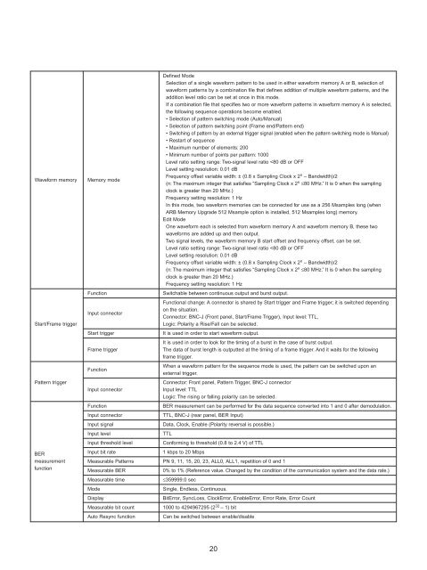
Waveform memoryStart/Frame triggerPattern triggerMemory modeFunctionInput connectorStart triggerFrame triggerFunctionInput connectorFunctionInput connectorInput signalInput levelInput threshold levelDefined ModeSelection of a single waveform pattern to be used in either waveform memory A or B, selection ofwaveform patterns by a combination file that defines addition of multiple waveform patterns, and theaddition level ratio can be set at once in this mode.If a combination file that specifies two or more waveform patterns in waveform memory A is selected,the following sequence operations become enabled.• Selection of pattern switching mode (Auto/Manual)• Selection of pattern switching point (Frame end/Pattern end)• Switching of pattern by an external trigger signal (enabled when the pattern switching mode is Manual)• Restart of sequence• Maximum number of elements: 200• Minimum number of points per pattern: 1000Level ratio setting range: Two-signal level ratio
BER measurementfunction(Option:<strong>MG3700A</strong>-031,<strong>MG3700A</strong>-131)External interfaceFunctionConnectorInput signalInput levelInput threshold levelInput impedanceAdjustable range of input timingInput bit rateMeasurable patternsMeasurable BERMeasurable bit countMeasurable error bitAuto ResyncMeasurement modeDisplayGPIB100BASE-TX EtherMemory cardSizeBER can be measured for data strings converted to 1s and 0s following demodulation.Rear panel, BER Input, BNC-J connectorData, Clock, Enable (Polarity reversal is possible)0 to 5 V0.20 to 3.00 V (0.05 V step)50 Ω, High impedance–1 to 15 clock (Data/Enable is adjusted for input Clock.)100 bps to 120 MbpsPN 9, 11, 15, 20, 23, ALL0, ALL1, ALT(01 repetition)PN 9fix, 11fix, 15fix, 20fix, 23fix, UserDefine0 to 10% (Reference value. Changed by the condition of the communication system and the data rate.)1000 to 4294967295 (2 32 – 1) bit1 to 2147483647 (2 31 – 1) bitOn, Off (When On is set, it becomes SyncLoss by the error detecting condition of Threshold and themeasurement is stopped. When Off is set, the detection of SyncLoss is not performed.)Threshold setting range:[numerator/denominator] Choose from denominator = 500, 5000, 50000,numerator = 1 to denominator/2, (Default: 200/500)Single, Continuous, EndlessBitError, SyncLoss, ClockError, Enable Error, SyncLoss Count, Overflow Data Count, OverflowSyncLoss, Error Rate, Error CountTarget of control: The functions except a power supply switch, local key, and contrast keys arecontrollable etc.Interface: SH1, AH1, T6, L4, TE0, SR1, RL1, PP0, DC1, DT1, C0, E2Connector: GPIB (rear panel, GPIB)Function: Waveform pattern transfer and control.Connector: Modular jack [Cat.5] 8pin (front panel and rear panel, Ethernet)In order to use the Ethernet connector of a front panel, it is necessary to short-circuit twoEthernet connectors of a rear panel by a U link cable (standard accessory).Function: Waveform pattern, a memory parameter, software, and CH table can be saved or recalledto/from a Compact-Flash card.Connector: Slot (front panel, CF Card)8.4 inch, 640 x 480 dots, color TFT LCDDisplay On/Off setting Panel display On/OffScreen saveVoltageFrequencyA currently displayed screen can be saved to HDD/CF card as a BMP file.AC 100 to 120 V, 200 to 240 V (–15/+10%, 250 V MAX)47.5 to 63 HzPower Power consumption ≤200 VATemperature OperatingStorage+5 to +45°C–20 to +60°CDimensions and massEMC426 (W) x 177 (H) x 451 (D) mm, ≤15 kg (excluding option)EN61326: 1997/A2: 2001 (Class A), EN61000-3-2: 2000 (Class A),EN61326: 1997/A2: 2001 (Annex A)LVD EN61010-1: 2001 (Pollution Degree 2)∗1 The following conditions are applied unless otherwise specified.Common to CW mode and modulation mode. [Continuous mode: Off, External ALC: Off, Frequency switching speed: Normal, Pulse modulation: Off], Onlyduring modulation mode [Input level to DAC (RMS): Full scale 14 dB to full scale 17 dB, Sampling rate: >100 kHz, Memory mode: Except combining twowaveform, IQ Output: Off, After CAL execution, During internal modulation]∗2 At modulation mode, ALC: Off21