ELSAG Datamat - enea-utmea
ELSAG Datamat - enea-utmea
ELSAG Datamat - enea-utmea
- No tags were found...

You also want an ePaper? Increase the reach of your titles
YUMPU automatically turns print PDFs into web optimized ePapers that Google loves.
ASTROMEPCIP/ASTROM ProjectFINAL CONFERENCEASsessment of resilience to ThReatsof cOntrol and data Management systemsof electrical transmission networkAgreement Number: HOME/2008/CIPS/018WP 2, Determination of the properties of Control and DataManagement systems of electrical transmission networks[Walter Caputo]“With the support of the Prevention, Preparedness and ConsequenceManagement of Terrorism and other Security-related Risks Programme''European Commission - Directorate-General Home Affairs''
ASTROMPower System complexity and criticalitiesComplexities• Wide area nature of network infrastructures• High Number of lines, nodes, …• Number of Protection, Monitoring, Control,Supervision, Defence, Automation Systems• Protection, Monitoring and Control Systems availabitlityand reliability• System expansions and upgrades (inevitable to meet theenergy demand and sustain reliability)• Market influences & Economic FactorsInterdependency introduces new criticalities• ICT-PS / PS-ICT dependency and inter-dependency– ICT system performances– PS system performance• Internal / external cascading effects• Coordination of Protection & Control systemsNatural and man induced eventsand phenomena cannot be fullycontrolled
ASTROMIdentification of the Boundaries andInterrelations of Electricity System and the ICTLegendaprimary frequency regulators: PFRsecondary frequency regulator: SFRprimary voltage regulatorers: AVRsecondary voltage regulators: PQRregional voltage regulators: RVR
ASTROMMonitoring and control:SCADA and EMSPower plantTransmissionnetworkPower plantPower plantNational DispatchingCentreControl room, RomeLumped loadMeasuresTopology statusDistribution (loads)DGV, P, Q, f, I, statusRTUdBSTATEESTIMATORSystem StateSecurityanalyses
ASTROMPower Control System’s boundariesSystem Control Center (SCC)NetworkLevelSW-HW SCADA 3^ generationFor Transmission and GenerationCommunication LayerWAN – LAN - PointToPointSubstationLevelSubstation Control System (SCS)Remote Terminal Unit (RTU)
ASTROMWP2 - METHODOLOGICAL STEPSSTEP 1What are the macro components ?STEP 2What are the capabilities of eachmacro component and how does it work ?STEP 3Which components and mission requirementsare really critical ?
ASTROMIdentification of Control and Data Management Systemfunctional ArchitectureSTEP 1- What are the macro components ? -
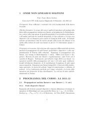
ASTROMIdentification of Control and Data Management Systemfunctional ArchitectureFigure 1 shows an example of SCADA Control Center architecture without theinclusion of network security.
ASTROMSCC System Components• SCC System ComponentsThe System Control Center (SCC) is a distributed system, with redundant servers performingcritical functions and managing the distribution of data to Consoles. There are several sets ofredundant servers performing various functions, each with a primary server and an alternateserver (secondary):— Application Servers (SCC-AS)• Core SCADA subsystems (SCC-AS-CS): This server is used mainly for dataprocessing functions, real-time and configuration database.• Database subsystems (SCC-AS-DBS): This server supports database for storingevents, status changes and measurements.• Advanced Application subsystems (SCC-AS-AAS): These servers support all EMS orDMS applications. The main characteristic of this server is its processing power. Morethan one server may be used for these applications.
ASTROMSCC System Components• Historical Databases (SCC-AS-HI): These servers support the database that containsall historical data. This information can also be used for system studies or operators’training. Data are forecasted or estimated for future values.• Configuration and administration (SCC-AS-CFG): This server is used for the control,management and maintenance of the whole SCADA system. From this server, theoperation mode of each server can be controlled and system backup functions can beordered.— Communication Front-Ends (SCC-FE)— External Communication Servers (SCC-ECS)
ASTROMSCC System ComponentsIn addition, there are several HMI consoles’ types:• Dispatcher Training Simulator Consoles (SCC-HMI-DC): used for training operators tomake correct decisions quickly under varying conditions of the power systemoperations.• Planning and Configuration consoles (SCC-HMI-PCFG): used mainly for HV networkconfiguration• Supervisor consoles (SCC-HMI-SC): used in runtime for monitoring and controlling HVnetwork• Maintenance console (SCC-HMI-MC): used to manage all the nodes (servers,consoles..) in terms of running status; diagnostic purpose; user and consolesconfiguration.• and finally a Mapboard (or MimicBoard) (SCC-MB): to have a quick andeasy view ofthe whole network.
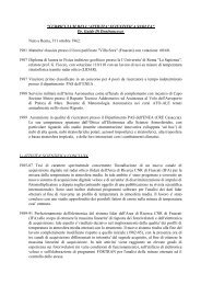
ASTROMIdentification of Control and Data Management Systemfunctional ArchitectureFigure 2 — Example of Substation Control System Architecture without Security shown.
ASTROMSCS System Components• SCS System ComponentsThe Substation Control System uses any number of devices integrated into a functional arrayby a communications technology for the purpose of monitoring, controlling and configuring thesubstation.All these information are collected by RTUs and sent to Control Center.Main components:– Data Concentrator (SCS-DC)– Supervisor Advanced Console (SCS-CLI + SCS-AHMI)– Remote Terminal Unit (SCS-RTU)
ASTROMIdentification of Control and Data Management Systemfunctional Architecture• Communication linksData exchange between substations and the SCADA master station offer several communicationinterconnections and architectures. The major consideration with the Master Station is with theamount of data that can be brought back from the substations. Due to communication channellimitations, there may not be enough bandwidth to support the desired amount of data that iscoming back from the substations to the control center.At least we have to consider three different level of communication links, that is:Control Center Data Network (SCC-LAN).Substation Data Network (SCC-LAN)Inter-control center communications (SCC-ICC)Inter SCADA Control Center and Substation Net (SCC-SCS-NET)
ASTROMTypical Physical Connections
ASTROMCommunication Link functional Architecture• Control Center LAN (SCC-LAN)The SCADA Control Center is based on Client-Server type architecture, consisting of a set ofprocessors and terminals (Workstations, Servers, printers,......) connected to the high speedlocal redundant network.Normally SCADA Control Center is based on a “flat-network” with double switches. All hardwareSubsystem have double Ethernet 10/100/1000 Mbps network card, configured in “teaming”Adaptive Fault-tolerance mode This means that the network can work both in case of a faulty ofswitch or if a Ethernet card doesn’t work on a server.The speed of the network cards is auto-adaptive by the settings of the network cards themselvesaccording to the speed output of the switches ports, and it is nominally operating at 100Mbps(Fast Ethernet mode) Full-duplex.
ASTROMSCC-LAN Protocols— ProtocolsThe communication between nodes or application processes in the SCC-LAN is basedon TCP/IP layer. Usually every vendor implements its own protocol over TCP and in aControl Center several protocols are implemented.
ASTROMIdentification of Control and Data Management Systemfunctional Architecture• Substation LAN (SCS-LAN)The primary communications activity of a master station is the acquisition of data from substations.The master station must communicate with IEDs such as RTUs, Data Concentrators, andGateways. In most applications, additional IEDs (such as relays and meters) are connected to oneof the other IEDs and do not communicate directly with the Master Station; however, there may besome IEDs that connect directly.The performance of the substation communications physical media has a direct effect on theperformance of the overall system. The speed and quality of the data acquisition is a primaryrequirement in the design of a SCADA system that must take into account the selection of thecommunications physical media.— ProtocolsIEC 61850 is the international standard that defines the hardware and communicationrequirements for all products within substation automation.
ASTROMCommunication Link functional Architecture• Inter-control center communications (SCC-ICC)Control centers are frequently connected together for either synchronizing data used in gridoperations or obtaining load data from distribution level systems. It is recommended that astandard protocol be used in order to ensure interoperability and minimize initial configurationeffort.— IEC 60870-6/TASE.2 (ICCP)The Inter-Control Center Communications Protocol (ICCP or IEC 60870-6/TASE.2) isbeing specified by utility organizations throughout the world to provide data exchangeover wide area networks (WANs) between utility control centers, utilities, power pools,regional control centers, and Non-Utility Generators. ICCP is also an internationalstandard: International Electrotechnical Commission (IEC) Telecontrol ApplicationService Element 2 (TASE.2).
ASTROMCommunication Link functional Architecture• Inter SCADA Control Center and Substation Net (SCC-SCS-NET)There are several types of physical connection between SCADA Control Center (Master Station)and Substations. All these links are usually dedicated serial lines in redundant configuration.- ProtocolsFor RTU to Control Centre communications:IEC 60870-5-101, while IEC 60870-5-104 is emerging.
ASTROMMACRO Components of the Power Control SystemCOMPONENTDESCRIPTIONSCC-HMI-DCSCC-HMI-PCFGSCC-HMI-SCSCC-HMI-MCSCC-MBSCS-DCSCS-RTUSCS-AHMISCC-LANSCC-SCS-NETSCS-LANSCC-ICCSCC-REMDIAGDispatcher consolesPlanning and Configuration consolesSupervisor consolesMaintenance consoleMimic BoardData ConcentratorRemote Terminal UnitSupervisor Advanced ConsoleControl Center LANInter SCADA Control Center and SubstationNetSubstation LANInter-Control Center CommunicationsRemote Diagnostic And Maintenance
ASTROMIdentification of relevant physical, logical andtechnological properties of systemsSTEP 2- What are the capabilities of each macrocomponent and how does it work ? -
ASTROMIdentification of relevant physical, logical andtechnological properties of systemsTaking into account what was introduced in STEP 1, we are going to explain the singlecomponents of a modern SCADA system in terms of hardware and software characteristics.Each logical component will be fully identified by:— Functionalities— Mission Requirements— Typical software— Typical hardware
ASTROMExample: SCC-FE - funcionalities• Communication Front-Ends (SCC-FE)The Communication Front-End is responsible for preparing, queuing and transmitting all datarequests to the RTUs. SCC-FE is also responsible for receiving, validating and processing all datasent from the RTUs to the Application Server (AS).— Main Functionalities:• RTU scanning• Measure and limit check processing• Digital input processing• Digital output processing• Sequence of Events (SOE) acquisition and archiving• Accumulator processing• Full update scans and RTU integrity errors• RTU diagnostics and communication channels
ASTROMExample: SCC-FE – Mission Requirements• Mission RequirementsTaking in to account all the functionalities previously defined, in the following the list of the missionrequirements of the SCC-FE component:• Management of Digital and Analog Signals (acquiring processing and dispatching)• Management of Remote Control of Remote Devices (processing and dispatching)• Communication management with the RTU (communication ports and modemsmanagement)• RTU Protocol management (IEC 60870-5-104; IEC 60870-5-101)
ASTROMExample: SCC-FE – Typical Software
ASTROMExample: SCC-FE – Typical Software – Technical sheetFunction Implementation NotesInterprocessingCommunicationSocket TCP (client/server)This is the main method to exchange databetween processes. Usually there is a mainprocess as a server (COMM-MAN). It providesdata exchange between all processes connected.Real Time Data BaseThe access is via proprietary libraries or dll. It isnecessary to authenticate the user (process)before using DatabaseShared memoryOnly for particular information to be sharedbetween processes. For example the list of nodesand process running on the system. This sharedmemory is of course private and reserved by SO.ProgrammingStandard C (POSIX compliant)gcc compilerLanguagesC++gcc compilerInternal Protocols Proprietary between processesExternal Protocols Proprietary between AS and FESSL SQLFor Relational DatabaseIEC 60870-5-104; IEC 60870-5-101between FE and RTUs
ASTROMExample: SCC-FE – Typical HardwareSCC-FE Server includes two process computers, one hot reserve of the other. Processors are soconnected that the process is managed by only one of them during normal operation (on-line). Thesecond processor, also active but with “hot” reserve functions (hot stand-by), will automaticallytake the process management in case of exclusion or malfunction of the first one.Therefore, the standby system will keep a constant updating of its Database (real-time and notreal-time) as regards the online one.This transfer of the process management is completed in a very short time (about fifteen seconds)and assures the input and output data integrity and coherence during the whole switching phase.During this phase, operability is suspended for no more than 15 seconds, after signaling that to theoperating consoles.
ASTROMExample: SCC-FE – Typical Hardware – Technical sheet(minimum requirements)Characteristic Standard Alternative NotesProcessor Mono (3.00GHz/6MB) Dual Core (1.86Ghz /4MB) Usually IntelMemory RAM 4 GB 6 GBHard Disk2x 73 GB SCSI 15k rpmHot Swap (RAID 1)-Controller Supported RAID 1 - Possible externalshared storageNetwork cards 2x 100/1000 Mbit -Media DVD reader DVD reader/writerInterfaces 1 serial; 4 USB -Redundancies Redundant Power Supply -O.S.Linux Enterprise Ed.SUSE/REDHATWindows 2003 Server
ASTROMDetermination of critical assets andfunctional system schemaSTEP 3-Which components and mission requirementsare really critical ? -
ASTROMOperating State in Power Control SystemThe criticizes of the each component of the Power Control System (PCS) are not fixed andunchangeable over time but could change if the condition of working of the system changes.On the basis of these considerations, first of all, it is necessary to define the Operating State of thePower Control System (in terms of Control & Data Management System) and a quantitative modelfor it.In particular we define three Operating State, that is:NORMALALERTEMERGENCY
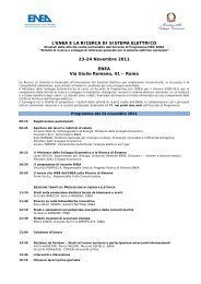
ASTROMQuantitative operating state modelWithout this quantification, the description would remain at a qualitative description level, as inmost of the current literature proposals.This model is based on a schematic representations (state models) joined withindex,measurements,thresholdFigure 17 – A schematic representation of ICT system and its quantification
ASTROMOperating State in Power Control SystemIn order to achieve an actual quantification of the PCS it is necessary to considerseparately the three main subsystems which constitute the whole PCS, that is:System Control Center (SCC)Communication Link Subsystem (CLS)Substation Control System (SCS)
ASTROMExample: Quantitative operating state model forControl Center (SCC)NORMAL ALERT EMERGENCYSCC-AS REDUNDANCYIf all SCC-AS BACK-UPARE ONIf the SCC-AS Backup is ON butone or more SCC-AS are OUTOF ORDERIf SCC-ASBackupis OUT OF ORDERIf SCC-FEIf SCC-FESCC-FE REDUNDANCYBACK-UPis ON-Backupis OUT OF ORDERNUMBER OF POSITIVESTATUS CHANGES(DUE TO COMMAND)NUMBER OF ALARM TO BEACQUIREDNumber of Status Changes =Number of commands sentCommands successfully withnumber of retry for commandfail = 0 2*K / minuteK = ……K = ……K = ……ANSWER TIME (DUE TOCOMMANDS)latency 2000 msec1000 msec
ASTROMDetermination of critical assets andfunctional system schemaeach component can be more or less critical depending onthe SCADA system working statusIn the following will be depict a summary schema in which every SCADA basecomponent will be shown in terms of critical aspects. In particular it is defined if acomponent is critical in according to its mission requirements and in which SCADAsystem working status.• Mission requirements for each Power Control Working status.• Critical Components for each Mission Requirement• Critical Components for each Power Control Working status
ASTROMMission requirements for each Power ControlWorking status.Mission Requirement NORMAL ALERT EMERGENCYManagement of Digital and Analog * * *SignalsManagement of Remote Control of * * *Remote DevicesMaintain real time database updated * * *and aligned on every node (RT DB).Store all the events messages coming * *from the connected subsystemSelect, retrieve and sort events during *operational mode without reducingperformancesGeneration Control * *Security Analysis (state estimator) *Store acquired equipment status and *measurements changesAS management and in particular *manual switchover (processing)FE management and in particular *manual switchover (processing)Data Acquisition - Switch to * *redundant communication path andchange communication port modes(processing)
ASTROMMission requirements for each Power ControlWorking status.Communication management with * *the RTU (communication ports andmodems management)RTU Protocol management (IEC * * *60870-5-104; IEC 60870-5-101)Exchange data coming from andtoward to External SystemOperator Console Access (manage * *authorization requests fromoperator)Display of configured diagrams, *equipments, devices for the simulatedcontrolled power network (off-line)Network management (off-line) *Design, configure or change all or * *some of the information, graphic anddata (related to electricalequipments), necessary to control andmonitoring the power network.Display of configured diagrams, *equipments, devices for the controlledpower networkDisplay of configured servers, clients,printers, lines and RTUs for theSCADA system.* *
ASTROMMission requirements for each Power ControlWorking status.AS management and in particularmanual switchover (issuingcommands)FE management and in particularmanual switchover (issuingcommands)Data Acquisition - Switch toredundant communication path andchange communication port modes(issuing commands)IEDs Protocol management (IEC61850)Display of configured diagrams,equipments, devices for the controlledpower substation.Redundant communication linkbetween each node in the ControlCenterSupport Proprietary SCADAprotocolRedundant communication linkbetween each node in the WAN(FE,DC,RTU)**** ** * ** ** * **
ASTROMMission requirements for each Power ControlWorking status.Redundant communication link *between each node in the substationautomation (DC,RTU,AHMI)Support IEDs Protocol (IEC 61850) *Exchange data between Control *Centers (IEC 60870-6 TASE.1)
ASTROMCritical Components for each Mission RequirementManagement of Digital andAnalog SignalsManagement of RemoteControl of Remote DevicesSCC-AS-CS SCC-FE SCC-HMI-SCSCC-AS-CS SCC-FE SCC-HMI-SCSCS-DCSCS-DCSCS-SC-AHMISCS-RTU-LOGICSCS-RTU-LOGICSCS-RTU-DAOSCS-RTU-DAISCC-SCS-NETSCC-SCS-NETMaintain real timedatabase updated andaligned on every node (RTDB).Store all the eventsmessages coming from theconnected subsystemSelect, retrieve and sortevents during operationalmode without reducingperformancesSCC-AS-CSSCC-AS-DBSSCC-AS-DBSSCC-AS-CSSCC-AS-CSGeneration ControlSCC-AS-AAS-EMSSCC-AS-CSSCC-FESCS-RTU-LOGICSCS-RTU-DAISCC-SCS-NETSecurity Analysis (stateestimator)Store acquired equipmentstatus and measurementschangesSCC-AS-AAS-EMSSCC-AS-HISCC-AS-CSSCC-AS-CS
ASTROMCritical Components for each Mission RequirementAS management and in particularmanual switchover (processing)SCC-AS-CFGFE management and in particularmanual switchover (processing)SCC-AS-CFGData Acquisition - Switch toredundant communication path andchange communication port modes(processing)Communication management with theRTU (communication ports andmodems management)RTU Protocol management (IEC60870-5-104; IEC 60870-5-101)SCC-AS-CFGSCC-FESCC-FESCC-SCS-NETSCC-SCS-NETSCC-SCS-NETSCS-DCSCS-DCSCS-RTU-LOGICSCS-RTU-LOGICExchange data coming from andtoward to External SystemSCC-ECSOperator Console Access (manage SCC-HMIauthorization requests from operator)Display of configured diagrams, SCC-HMI-DCequipments, devices for the simulatedcontrolled power network (off-line)SCC-AS-CS
ASTROMCritical Components for each Mission RequirementDisplay of configured servers, clients,printers, lines and RTUs for theSCADA system.SCC-HMI-MC SCC-AS-CS
ASTROMCritical Components for each Power ControlWorking statusCOMPONENT NORMAL ALERT EMERGENCY DESCRIPTIONSCC-AS-CSCore SCADA subsystemsSCC-AS-DBSSCC-AS-HISCC-AS-CFGSCC_FESCC-AS-AAS-EMSSCC-AS-AAS-WSSCC-ECSSCC-HMI-DCSCC-HMI-PCFGSCC-HMI-SCSCC-HMI-MCSCC-MBSCS-DCSCS-RTUSCS-AHMISCC-LANSCC-SCS-NETSCS-LANSCC-ICCSCC-REMDIAGDatabase subsystemsHistorical DatabasesConfiguration and administrationData Acquisition Front EndApplication Server EMSWeb ServerExternal Communication ServersDispatcher consolesPlanning and Configuration consolesSupervisor consolesMaintenance consoleMimic BoardData ConcentratorRemote Terminal UnitSupervisor Advanced ConsoleControl Center LANInter SCADA Control Center andSubstation NetSubstation LANInter-Control CenterCommunicationsRemote Diagnostic And Maintenance