ACCESSORY KIT INSTALLATION MANUAL - UPGNet
ACCESSORY KIT INSTALLATION MANUAL - UPGNet
ACCESSORY KIT INSTALLATION MANUAL - UPGNet

Create successful ePaper yourself
Turn your PDF publications into a flip-book with our unique Google optimized e-Paper software.
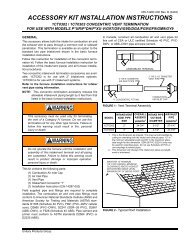
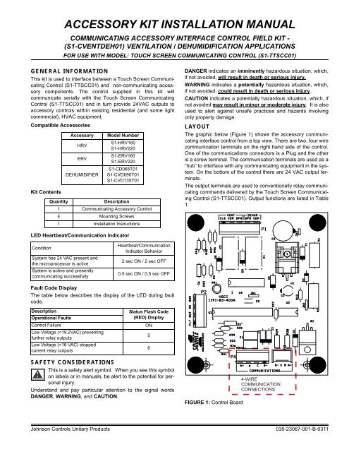
<strong>ACCESSORY</strong> <strong>KIT</strong> <strong>INSTALLATION</strong> <strong>MANUAL</strong>COMMUNICATING <strong>ACCESSORY</strong> INTERFACE CONTROL FIELD <strong>KIT</strong> -(S1-CVENTDEH01) VENTILATION / DEHUMIDIFICATION APPLICATIONSFOR USE WITH MODEL: TOUCH SCREEN COMMUNICATING CONTROL (S1-TTSCC01)GENERAL INFORMATIONThis kit is used to interface between a Touch Screen CommunicatingControl (S1-TTSCC01) and non-communicating accessorycomponents. The control supplied in this kit willcommunicate serially with the Touch Screen CommunicatingControl (S1-TTSCC01) and in turn provide 24VAC outputs toaccessory controls within existing residential (and some lightcommercial), HVAC equipment.Compatible AccessoriesKit ContentsAccessoryHRVERVDEHUMIDIFIERModel NumberS1-HRV160S1-HRV220S1-ERV160S1-ERV220S1-CD065T01S1-CVD090T01S1-CVD135T01QuantityDescription1 Communicating Accessory Control4 Mounting Screws1 Installation InstructionsDANGER indicates an imminently hazardous situation, which,if not avoided, will result in death or serious injury.WARNING indicates a potentially hazardous situation, which,if not avoided, could result in death or serious injury.CAUTION indicates a potentially hazardous situation, which, ifnot avoided may result in minor or moderate injury. It is alsoused to alert against unsafe practices and hazards involvingonly property damage.LAYOUTThe graphic below (Figure 1) shows the accessory communicatinginterface control from a top view. There are two, four wirecommunication terminals on the right hand side of the control.One of the communications connectors is a Plug and the otheris a screw terminal. The communication terminals are used as a“hub” to interface with any communicating equipment in the system.On the bottom of the control there are 24 VAC output terminals.The output terminals are used to conventionally relay communicatingcommands delivered by the Touch Screen CommunicatingControl (S1-TTSCC01). Output functions are listed in Table1.LED Heartbeat/Communication IndicatorConditionSystem has 24 VAC present andthe microprocessor is active.System is active and presentlycommunicating successfullyHeartbeat/CommunicationIndicator Behavior2 sec ON / 2 sec OFF0.5 sec ON / 0.5 sec OFFFault Code DisplayThe table below describes the display of the LED during faultcode.DescriptionOperational FaultsControl FailureLow Voltage (
035-23067-001-B-0311TABLE 1: Terminal DesignationsSignal Definition LabelData Non-inverted Signal A (+)Data Inverted Signal B (–)Low Voltage Power Common (Data Ground) 24 VAC (Common) CLow Voltage Power Hot 24 VAC (Hot) RVentilation N.C. Output Ventilation Normally Closed VENT CLSVentilation Common Output Ventilation Common VENT COMVentilation N.O. Output Ventilation Normally Open VENT OPNDehumidification N.O. Output Dehumidification Normally Open DEHUM OPNDehumidification Common Output Dehumidification Common DEHUM COMFloat Switch Connection Input (not active) Dehumidification Float Switch Input FLT SWTOutdoor Sensor Connection Input (not active) Outdoor Sensor Ventilation Input OD SNRAPPLICATIONSThere are three generic applications that this kit was designedto address.1. A non-communicating ventilator.2. A non-communicating dehumidifier.3. A non-communicating ventilator with a non-communicatingdehumidifier.Physical Installation1. Use the template at the end of this document to mark fourholes inside the control assembly area of the indoor unit.See Figure 2.NOTICEIf there is not space for the template anywhere in the suggestedlocation, you may need to place the interface controlon the outside of the unit. In the event that the control cannotbe placed inside of the unit, the installer may need to build aprotective box around the control to keep it safely stored awayfrom moisture and personal contact.2. Using a 1/8” drill bit, drill holes where marked (in Step 1).3. Attach the Communicating Accessory Control (using thescrews provided) over the pre-drilled holes.4. Connect the applicable 24 VAC outputs from the CommunicatingAccessory Control to the 24 VAC inputs on the noncommunicatingaccessory control board(s).See Figures 4-7.5. Connect all communicating system components. See Figures4-7.6. Apply power to system.7. Follow Installation setup screens on the Touch Screen CommunicatingControl (see Touch Screen CommunicatingControl installation manual for more information).a. Select “Add Device” on the main, Edit/Add Devicesscreen.b. A list of possible devices available will be loaded forselection. Select the icon that represents the devicebeing installed.c. The next screen allows the user to add a model andserial number to the device details for future reference.Simply press the space that indicates “Model Number”or “Serial Number”. This will activate the keyboard forinput.d. When all desired information has been entered, pressthe “Done” button in the lower right hand corner of thescreen.e. If installing additional devices, repeat steps a throughd for each device being installed.f. Once complete, press Yes to save all information, orNo to continue editing.8. If a dehumidifier is being installed, select the desired dehumidificationcontrol settings before exiting Service Mode onthe Touch Screen Communicating Control, (see TouchScreen Communicating Control installation manual for moreinformation).9. If a ventilator is being installed, select the desired ventilationsettings before exiting Service Mode on the Touch ScreenCommunicating Control, (see Touch Screen CommunicatingControl installation manual for more information).NOTICEThe ERV/HRV control switch must be set to“INTER”(Intermittent).2 Johnson Controls Unitary Products
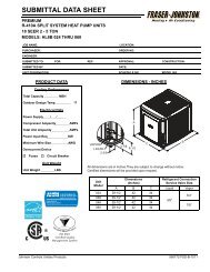
035-23067-001-B-0311COMMUNICATING SYSTEM IMPLEMENTATION - GENERICCOMMUNICATING SYSTEM IMPLEMENTATION - DEHUMIDIFIERTOUCH SCREENCOMMUNICATINGCONTROLCOMMUNICATING<strong>ACCESSORY</strong>INTERFACE CONTROLDAMPERCONTROLTOUCH SCREENCOMMUNICATINGCONTROLCOMMUNICATING<strong>ACCESSORY</strong>INTERFACE CONTROLDEHUNIDIFIERCONTROLA+A+A+A+RCB-B-DEHUM VENTRCB-CLSCOMOPNOPNCOMFLTCLOSECOMOPENTRANFORMER(24 VAC to 120 VACRCB-B-DEHUM VENTRCB-CLSCOMOPNOPNCOMFLTRf Cf Gs Gh W DHHVAC EQUIPSWTSWTODODSNRSNRFIGURE 5: Generic Ventilator ApplicationNOTICEThe wiring diagram shows a connection for a damper that isnormally closed. If a normally open damper is used, thenremove the normally open wire (solid line) and connect thenormally closed wire (dashed line).FIGURE 6: 90 & 135 Pints per Day Dehumidifiers ApplicationCOMMUNICATING SYSTEM IMPLEMENTATION - DEHUMIDIFIERTOUCH SCREENCOMMUNICATINGCONTROLA+RCOMMUNICATING<strong>ACCESSORY</strong>INTERFACE CONTROLA+RDEHUNIDIFIERCONTROLCB-B-CB-CLSDEHUM VENTCOMOPNOPNCOMFLTSWTODSNRFLOATSWITCHREMOTEG-STATR-HVACG-HVACFIGURE 7: 65 Pints per Day Dehumidifiers Application4 Johnson Controls Unitary Products
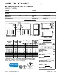
035-23067-001-B-03114.0”3.5”FIGURE 8: Hole TemplateJohnson Controls Unitary Products 5
NOTESSubject to change without notice. Published in U.S.A.Copyright © 2011 by Johnson Controls, Inc. All rights reserved.Johnson Controls Unitary Products5005 York DriveNorman, OK 73069035-23067-001-B-0311Supersedes: 035-23067-001-A-0111