ACCESSORY KIT INSTALLATION INSTRUCTIONS - UPGNet
ACCESSORY KIT INSTALLATION INSTRUCTIONS - UPGNet
ACCESSORY KIT INSTALLATION INSTRUCTIONS - UPGNet

You also want an ePaper? Increase the reach of your titles
YUMPU automatically turns print PDFs into web optimized ePapers that Google loves.
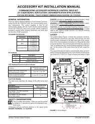
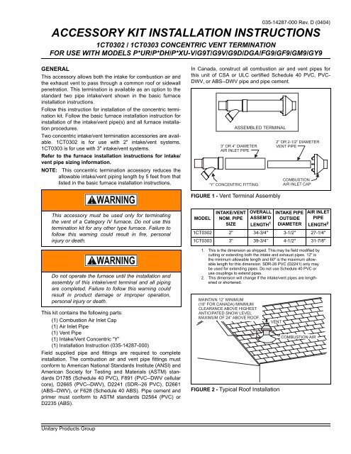
035-14287-000 Rev. D (0404)VERTICAL ROOF MOUNTINGNOTE: Roof mounting is the recommended intake/vent location.This allows less intake air contaminants and alsoreduces complaints caused by exhaust vapors nearground level.1. Determine pipe diameter from furnace installationinstructions.2. Determine correct concentric vent termination accessoryfor the pipe diameter selected.3. Determine the best location for the intake/vent.4. Cut a 4" diameter hole for 1CT0302, 2" kit, or a 5" holefor 1CT0303, 3" kit.5. Partially assemble concentric vent termination kit. Cleanand cement using procedures explained in the furnaceinstallation instructions.7. Secure assembly to roof structure as shown in Figure 3using field supplied metal strapping or equivalentsupport material.NOTE: Ensure termination height is above roof surface oranticipated snow level (minimum 12 inches. in U.S. orminimum 18 inches. in Canada) as shown in Figures2 & 3.NOTE: If assembly is too short to meet height requirement,the 2 pipes supplied in the kit may be replaced byusing same diameter, field supplied SDR--26 PVC(D2241) pipe. Do not use Schedule 40 PVC or couplingsto extend pipes. The additional wall thicknesswill restrict combustion air and may cause operationalproblems. Do not extend air inlet pipe more than 60"(refer to Figure 3).COMBUSTION AIRROOF WEATHERSEAL/FLASHING(FIELD SUPPLIED)VENTVENTFIGURE 3 - Typical Roof InstallMAINTAIN 12” (18” FOR CANADA)MINIMUM CLEARANCE ABOVEHIGHEST ANTICIPATED SNOWLEVEL. MAXIMUM OF 24” ABOVEROOF.SUPPORT(FIELD SUPPLIED)ELBOW(FIELD SUPPLIED)COMBUSTION AIRA. Cement “Y” concentric fitting to larger diameter airinlet pipe (refer to Figure 1).B. Cement combustion air inlet cap to smaller diameterpipe (refer to Figure 1).6. Install “Y” concentric fitting and pipe assembly throughthe structure's hole and field supplied roof boot/flashing.NOTE: Do not allow insulation to accumulate inside assemblywhen installing through hole.Do not use field supplied couplings to extend pipes.8. Install combustion air inlet cap and small diameter pipeassembly into roof penetration. Make sure smalldiameter pipe is cemented and bottomed in “Y”concentric fitting.9. Cement furnace combustion air and vent pipes toconcentric vent termination assembly. Refer to Figure 3for proper pipe attachment.10. Operate furnace through one heat cycle to verify propersystem operation.HORIZONTAL SIDEWALL MOUNTINGNOTE: In all horizontal intake/vent applications the followingitems should be considered before a final location isdetermined.A. Refer to 2--pipe vent clearances in the furnaceinstallation instructions to determine allowable locationsand required clearances.B. If venting multiple units using multiple concentricvents, refer to Figures 4, 5 & 6 for specific clearances.C. Do not locate this termination where it is subjectedto prevailing winds.D. Do not locate this termination where it is likely toreceive physical damage.E. Do not locate this termination where vent vapors areobjectionable, or may damage the structure, plantsor air conditioning condensing unit.2 Unitary Products Group
035-14287-000 Rev. D (0404)24” MINIMUM(between end bell edges)12” MINIMUM36” MINIMUMROOF OVERHANGROOFOVERHANG12” MINIMUM1”VENT1” VENTCOMBUSTION AIRMAINTAIN 12” CLEARANCEABOVE HIGHEST ANTICIPATEDSNOW LEVEL OR GRADECOMBUSTION AIRMAINTAIN 12” CLEARANCEABOVE HIGHEST ANTICIPATEDSNOW LEVEL OR GRADE.FIGURE 4 - Sidewall Termination for Multiple VerticalConcentric VentFIGURE 6 - Sidewall Termination for Multiple HorizontalConcentric VentROOFOVERHANG12” MINIMUMNOTE:SECURING STRAP MUST BEFIELD INSTALLED TO PREVENTMOVEMENT OF TERMINATION<strong>KIT</strong> IN SIDEWALL.COMBUSTIONAIRSTRAP(FIELD SUPPLIED)1”VENTVENTVENTCOMBUSTION AIRMAINTAIN 12” CLEARANCEABOVE HIGHEST ANTICIPATEDSNOW LEVEL OR GRADECOMBUSTIONAIRELBOW(FIELD SUPPLIED)1”COMBUSTIONAIR INLETVANES TOWALLFIGURE 5 - Sidewall Termination for Concentric VentFIGURE 7 - Sidewall Termination Details for ConcentricVentUnitary Products Group 3
1. Determine pipe diameter from furnace installation manual.2. Determine correct concentric vent termination accessoryfor the pipe diameter selected.3. Determine the best location for the intake/vent.4. When installing multiple concentric vents, the followingguidelines should be followed:A. Multiple Concentric Vents should not be installeddirectly above one another unless separated by aminimum distance of 36 inches.B. Multiple Concentric Vents should be installed wherethe horizontal distance between the end bells ofeach air intake is greater than 24" to prevent a recirculationof flue gas from one vent to the adjacent airoutlet.Recirculation of flue gases may occur causing theintake pipe to freeze shut during cold weatheroperation if the venting system is not installed perthese guidelines.5. Cut a 4" diameter hole for 1CT0302, 2" kit, or a 5" holefor 1CT0303, 3" kit.6. Partially assemble concentric vent termination kit. Cleanand cement using procedures explained in the furnaceinstallation instructions.A. Cement “Y” concentric fitting to larger diameter airinlet pipe (refer to Figure 1).B. Cement combustion air inlet cap to smaller diameterpipe (refer to Figure 1).7. Install “Y” concentric fitting and pipe assembly throughthe structure's hole.NOTE: Do not allow insulation to accumulate inside assemblywhen installing through hole.8. Install combustion air inlet and small diameter pipeassembly into “Y” concentric fitting and large pipeassembly. Make sure small diameter pipe is bottomedand cemented in “Y” concentric fitting.9. Secure assembly to structure as shown in Figure 7 usingfield supplied metal strapping or equivalent supportmaterialNOTE: Maintain clearance dimensions as shown in Figure 4,5, 6 & 7.NOTE: If assembly needs to be extended to allow side wallthickness requirement, the 2 pipes supplied in the kitmay be replaced by using same diameter, field suppliedSDR--26 PVC (D2241) pipe. Do not use Schedule40 PVC or couplings to extend pipes. Theadditional wall thickness will restrict combustion airand may cause operational problems. Do not extendair inlet pipe more than 60 inches (Refer to Figure 7).Do not use field--supplied couplings to extend pipes.10. Cement furnace combustion air and vent pipes toconcentric vent termination assembly. Refer to Figure 7for proper pipe attachment.11. Operate furnace through one heat cycle to verify propersystem operation.Subject to change without notice. Printed in U.S.A. 035-14287-000 Rev. D (0404)Copyright © by York International Corp. 2004. All rights reserved. Supersedes: 035-14287-000 Rev. C (0304)Unitary 5005 NormanProduct York OKGroup Drive 73069