A Dynamical System Approach to Realtime Obstacle ... - LASA - EPFL
A Dynamical System Approach to Realtime Obstacle ... - LASA - EPFL
A Dynamical System Approach to Realtime Obstacle ... - LASA - EPFL

You also want an ePaper? Increase the reach of your titles
YUMPU automatically turns print PDFs into web optimized ePapers that Google loves.
Au<strong>to</strong>nomous RobotsDOI 10.1007/s10514-012-9287-yA <strong>Dynamical</strong> <strong>System</strong> <strong>Approach</strong> <strong>to</strong> <strong>Realtime</strong> <strong>Obstacle</strong> AvoidanceS.M. Khansari-Zadeh · Aude BillardReceived: 1 May 2011 / Accepted: 8 March 2012Abstract This paper presents a novel approach <strong>to</strong> real-timeobstacle avoidance based on dynamical systems (DS) thatensures impenetrability of multiple convex shaped objects.The proposed method can be applied <strong>to</strong> perform obstacleavoidance in Cartesian and Joint spaces and using bothau<strong>to</strong>nomous and non-au<strong>to</strong>nomous DS-based controllers.<strong>Obstacle</strong> avoidance proceeds by modulating the original dynamicsof the controller. The modulation is parameterizableand allows <strong>to</strong> determine a safety margin and <strong>to</strong> increase therobot’s reactiveness in the face of uncertainty in the localizationof the obstacle. The method is validated in simulationon different types of DS including locally and globallyasymp<strong>to</strong>tically stable DS, au<strong>to</strong>nomous and non-au<strong>to</strong>nomousDS, limit cycles, and unstable DS. Further, we verify it inseveral robot experiments on the 7 degrees of freedom BarrettWAM arm.Keywords <strong>Realtime</strong> obstacle avoidance · Nonlineardynamical system · Harmonic potential function · Robotmanipula<strong>to</strong>r1 IntroductionIn our quest <strong>to</strong> develop robots that react <strong>to</strong> arbitrary forms ofperturbations, we seek methods by which this reactivity willbe effortless and will unfold naturally from the control law.Imagine you are being served tea by a robot. As the robot isabout <strong>to</strong> pour the boiling liquid in the cup you are holding,you sneeze. As a result of your sudden hiccup, the cup is displacedand your hand is now in the way of the robot in placeof the cup. Surely, you wish the robot would be able <strong>to</strong> react<strong>LASA</strong> Labora<strong>to</strong>ry, School of Engineering, Ecole Polytechnique Federalede Lausanne (<strong>EPFL</strong>), CH 1015, Lausanne, SwitzerlandTel.: (+41) 21 693 5464Fax: (+41) 21 693 7850E-mail: {mohammad.khansari;aude.billard}@epfl.chswiftly, so as <strong>to</strong> redirect its motion <strong>to</strong> the cup while avoidingyour hand. These are examples of fast perturbations thatrequire a reactivity of the order of the second. These encompassa wide variety of perturbations dealt with by roboticssuch as: when an obstacle suddenly appears in the robot’spath, when the target moves, or when the robot is pushedaway from its trajec<strong>to</strong>ry while in motion. In these situations,there is no time <strong>to</strong> re-plan no matter how fast the replanningtechnique may be and hence alternative techniques must besought.<strong>Dynamical</strong> systems-based approaches <strong>to</strong> robot controloffer such robustness <strong>to</strong> real-time perturbations. When controlledthrough a <strong>Dynamical</strong> <strong>System</strong> (DS), a robot motionunfolds in time with no need <strong>to</strong> re-plan. In this paper, wepropose an obstacle avoidance algorithm that can be integratedin<strong>to</strong> existing DS-based motion control approaches,while retaining the swiftness and robustness provided bythese approaches. In the presented method, we assume thatthe robot motion is driven by a continuous and differentiableDS in the absence of obstacle(s). This DS is provided by theuser, and henceforth we will call it the original DS. Giventhe original DS and an analytical formulation describing thesurface of obstacles, our algorithm is able <strong>to</strong> instantly modifythe robot’s trajec<strong>to</strong>ry <strong>to</strong> avoid collisions with obstacles.Our approach has two main features: 1) As it only requiresthe differentiability of the original DS, it can be applied on alarge set of DS including locally and globally asymp<strong>to</strong>ticallystable DS, au<strong>to</strong>nomous and non-au<strong>to</strong>nomous DS, limit cycles,unstable DS, etc., and 2) It does not modify the criticalpoints of the original DS. Thus the attrac<strong>to</strong>rs of the originalDS are also the attrac<strong>to</strong>rs of the modulated DS.The rest of this paper is structured as follows: Section 2describes main existing obstacle avoidance methods in theliterature. Section 3 formalizes our obstacle avoidance algorithmfor robot motions in the presence of a convex obstacle.Section 4 discusses the stability of the control law after ap-
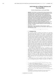
A <strong>Dynamical</strong> <strong>System</strong> <strong>Approach</strong> <strong>to</strong> <strong>Realtime</strong> <strong>Obstacle</strong> Avoidance 3the space in<strong>to</strong> regions affected by a single obstacle at most.To avoid the problem of partitioning, Waydo and Murray(2003) developed an alternative formulation using a continuousweighting fac<strong>to</strong>r. Similarly <strong>to</strong> (Feder and Slotine, 1997),this work only considered moving obstacles with constantvelocity. A major advantage of harmonic potential functionsover other potential functions is that they ensure that thetarget is the only attrac<strong>to</strong>r of the system. Unfortunately, inpractice, requiring that the motions of both the robot and theobstacle follow harmonic functions may be <strong>to</strong>o limiting.In this paper we propose a local obstacle avoidance approachwhich can be used <strong>to</strong> locally modify the robot motionsthat are generated by a DS. The proposed method ensuresthat this local modification of trajec<strong>to</strong>ries does notchange the main properties of the original DS. For instance,if the original DS is globally stable (i.e. all trajec<strong>to</strong>ries reachthe target point) when there is no obstacle in the robot workingspace, it also remains stable in the presence of obstacles.The system described above could also be pictured as a hybridcontroller in the sense that: the globally stable DS is theglobal planner generating trajec<strong>to</strong>ries that always reach thetarget, and the local planner is the proposed method that deformsthe generated trajec<strong>to</strong>ry in the presence of obstacles.Both the path generation and deformation are done simultaneouslyat each time step. This approach is similar, in spirit,<strong>to</strong> the harmonic potential functions. The main differenceslies in that our approach does not require the robot <strong>to</strong> followharmonic functions, hence it can be applied <strong>to</strong> a larger set ofrobot motions.3 <strong>Obstacle</strong> Avoidance FormulationConsider a state variable ξ ∈ R d that defines the state of arobotic system. Its temporal evolution may be governed byeither an au<strong>to</strong>nomous (time-invariant) or non-au<strong>to</strong>nomous(time-varying) DS according <strong>to</strong>:˙ξ = f (ξ ), f : R d ↦→ R d au<strong>to</strong>nomous DS (1)˙ξ = f (t,ξ ), f : R + × R d ↦→ R d non-au<strong>to</strong>. DS (2)where f (.) is a continuous function (we further use the notationf (.) <strong>to</strong> refer <strong>to</strong> both au<strong>to</strong>nomous and non-au<strong>to</strong>nomousDS). Given an initial point {ξ } 0 , the robot motion alongtime can be computed by integrating f (.) recursively:{ξ } t = {ξ } t−1 + f (.)δt (3)where δt is the integration time step and t is a positive integer.Figs. 1 and 3 illustrate a few examples of such functions.Next we show how we can induce a modulation on ourgeneric motion due <strong>to</strong> the presence of an obstacle. We firstconsider a hyper-sphere obstacle. We then extend this model<strong>to</strong> convex objects.3.1 Hyper-Sphere <strong>Obstacle</strong>sConsider a d-dimensional hyper-sphere object centered atξ o with radius r o . The object creates a modulation throughoutthe robot’s state space, which is conveyed through thenon-linear function ϕ s (ξ ;ξ o ,r o ) : R d ↦→ R d as follows 1 :ϕ s (ξ ;ξ o ,r o ) = (1 +(r o ) 2(ξ − ξ o ) T (ξ − ξ o ) )(ξ − ξ o ) (4)where (.) T denotes the transpose. To determine how ϕ modulatesthe velocity of the robot, we compute the Jacobianwhich yields:M s (ξ ;ξ o ,r o ) = ∇ϕ s (ξ ;ξ o ,r o ) (5)To simplify the notation, we express the modulation ina frame of reference centered on the object and define ˜ξ =ξ − ξ o :M s ( ˜ξ ;r o ) = I + ( ro˜ξ T ˜ξ )2 ( ˜ξ T ˜ξ I − 2 ˜ξ ˜ξ T ) (6)where I is the identity matrix. We call M s the dynamic modulationmatrix. The final model for real-time avoidance ofspherical obstacles can be obtained by applying the dynamicmodulation matrix <strong>to</strong> the original DS given by Eqs. (1)-(2):˙ξ = M s ( ˜ξ ;r o ) f (.) (7)M s ( ˜ξ ;r o ) in Eq. (7) is a modulation fac<strong>to</strong>r that locallydeforms the original dynamics f such that the robot doesnot hit the obstacle.□Theorem 1 Consider a d-dimensional static hyper-sphereobstacle in R d with center ξ o and radius r o . The obstacleboundary consists of the hyper-surface X b ⊂ R d = {ξ ∈R d : ∥ξ − ξ o ∥ = r o }. Any motion {ξ } t , t = 0..∞ that startsoutside the obstacle, i.e. ∥{ξ } 0 − ξ o ∥ > r o , and evolves according<strong>to</strong> Eq. (7) never penetrates in<strong>to</strong> the obstacle, i.e.∥{ξ } t − ξ o ∥ ≥ r o .Proof: See Appendix A.Fig. 1 illustrates the effect of the modulation induced bysuch a spherical object on two and three-dimensional flows.As it is illustrated, in both cases the flow is deflected properlyand it passes the obstacle.1 The development of Eq. (4) was partly inspired by the complex potentialfunction that models the uniform flow around a circular cylinder(Milne-Thomson, 1960). In both formulations the modulation ofthe flow due <strong>to</strong> the object’s presence decreases quadratically with thedistance <strong>to</strong> the center of the object (see the second term in Eq. (4)). Themain difference between the two approaches lies in their functionality.Eq. (4) is a d-dimensional vec<strong>to</strong>r and its Jacobian is a d × d matrixwhich can be used <strong>to</strong> modulate the original flow. In contrast, the complexpotential function is a scalar value, and its derivative directly givesthe modified flow in the presence of the obstacle.
4 S.M. Khansari-Zadeh, Aude BillardTangential Hyper-Plane Deflection Hyper-PlaneTangential Hyper-Plane ξ2ξ2 ξ 1(a) Two dimensional exampleξ 1Fig. 2 Illustration of the tangential hyper-plane and its basis (left), andthe deflection hyper-plane (right) for a 3-dimensional object.ξ3ξ 2ξ 1ξ3ξ 2(b) Three dimensional exampleFig. 1 Effect of the modulation induced by a spherical obstacle (locatedat the origin and with radius r o = 2) on (a) a two dimensional flowgenerated by ˙ξ 1 = 1.0 and ˙ξ 2 = sin(ξ 1 ), and (b) a three dimensionalflow generated by ˙ξ 1 = 1.0, ˙ξ 2 = −sin(ξ 2 /4)sinξ 1 , and ˙ξ 3 = sinξ 1 .3.2 Convex <strong>Obstacle</strong>sSuppose a continuous function Γ ( ˜ξ ) that projects R d in<strong>to</strong> R.The function Γ ( ˜ξ ) has continuous first order partial derivatives(i.e. C 1 smoothness) and increases mono<strong>to</strong>nically with∥ ˜ξ ∥. The level curves of Γ (i.e. Γ ( ˜ξ ) = c, ∀c ∈ R + ) enclosea convex region. By construction, the following relationholds at the surface of the obstacle:Γ ( ˜ξ ) = 1 (8)For example Γ ( ˜ξ ) : ∑ d i=1 ( ˜ξ i /a i ) 2 = 1 corresponds <strong>to</strong> ad-dimensional ellipsoid with axis lengths a i . We can dividethe space spanned by Γ in<strong>to</strong> three regions X o , X b , andX f <strong>to</strong> distinguish between points inside the obstacle, at itsboundary, and outside the obstacle respectively:Interior points : X o = {ξ ∈ R d : Γ ( ˜ξ ) < 1} (9)Boundary points : X b = {ξ ∈ R d : Γ ( ˜ξ ) = 1} (10)Free region : X f = {ξ ∈ R d : Γ ( ˜ξ ) > 1} (11)At each point ξ b ∈ X b on the outer surface of the obstacle,we can compute a tangential hyper-plane defined byits normal vec<strong>to</strong>r n( ˜ξ b ):n( ˜ξ[ b ∂Γ ( ˜ξ) =b )··· ∂Γ ( ˜ξ ] b T)∂ξ1b ∂ξdb (12)By extension, we can compute a deflection hyperplaneat each point ξ ∈ X f outside the obstacle with normal:n( ˜ξ[) = ∂Γ ( ˜ξ )··· ∂Γ ( ˜ξ] T)(13)∂ξ 1 ∂ξ dξ 1Each point on the deflection hyper-plane can be expressedas a linear combination of a set of (d − 1) linearly independentvec<strong>to</strong>rs. These vec<strong>to</strong>rs form a basis of the deflectionhyper-plane. One particular set of such vec<strong>to</strong>rs e 1 ,...,e d−1is 2 :⎧⎪⎨ − ∂Γ ( ˜ξ )j = 1e i j( ˜ξ∂ξ i) =∂Γ ( ˜ξ )j = i ≠ 1∂ξ 1 ⎪⎩0 j ≠ 1, j ≠ ii ∈ 1..d −1, j ∈ 1..d (14)where e i j corresponds <strong>to</strong> the j-th component of the i-th basisvec<strong>to</strong>r. Fig. 2 illustrates the tangential and the deflectionhyper-planes for a three-dimensional object.As in the case of the spherical object, we can determinea modulation matrix M( ˜ξ ) given by 3 :M( ˜ξ ) = E( ˜ξ ) D( ˜ξ ) E( ˜ξ ) (−1) (15)with the matrices of basis vec<strong>to</strong>rs E( ˜ξ ) and associated eigenvaluesD( ˜ξ ):E( ˜ξ[) = n( ˜ξ ) e 1 ( ˜ξ ) ··· e d−1 ( ˜ξ])⎡λ 1 ( ˜ξ ) 0D( ˜ξ ⎢) = ⎣. ..where⎧⎨λ 1 ( ˜ξ ) = 1 − 10 λ d ( ˜ξ )|Γ ( ˜ξ )|⎩λ i ( ˜ξ ) = 1 + 1|Γ ( ˜ξ )|⎤(16)⎥⎦ (17)2 ≤ i ≤ d(18)The dynamic modulation matrix M( ˜ξ ) propagates theinfluence of the obstacle on the motion flow. The result of2 In case ∂Γ ( ˜ξ )/∂ξ 1 vanishes, the vec<strong>to</strong>rs are no longer linearlyindependent and one should choose another index for the derivativewhich is non-zero.3 Derivation of Eqs. (15)-(16) are inspired from the proof of Theorem1. For a spherical obstacle, these equations yield <strong>to</strong> the same resultgiven by Eq. (6).
A <strong>Dynamical</strong> <strong>System</strong> <strong>Approach</strong> <strong>to</strong> <strong>Realtime</strong> <strong>Obstacle</strong> Avoidance 5Eq. (15) is invariant <strong>to</strong> the choice of the basis e 1 ..e d−1 . Furthermore,the matrix of basis vec<strong>to</strong>r is invertible in R d \ξ o . At the obstacle reference point ξ o , the deflection hyperplaneis undefined; however, this does not cause any problemsince ξ o is a point inside the obstacle (recall Γ (0) < 1).Moreover, since Γ ( ˜ξ ) mono<strong>to</strong>nically increases with ∥ ˜ξ ∥,the matrix of eigenvalues and by extension the dynamic modulationmatrix converge <strong>to</strong> the identity matrix as the distance<strong>to</strong> the obstacle increases. Hence, the effect of the dynamicmodulation matrix is maximum at the boundaries of the obstacle,and vanishes for points far from it.Similarly <strong>to</strong> the hyper-sphere obstacle avoidance givenby Eq. (7), we can apply the modulation given by Eq. (15)on our original motion flow f which yields:˙ξ = M( ˜ξ ) f (.) (19)□Theorem 2 Consider a convex manifold Γ ( ˜ξ ) = 1 that enclosesa static d-dimensional obstacle with respect <strong>to</strong> a referencepoint ξ o inside the obstacle. A motion {ξ } t , thatstarts outside the obstacle, i.e. Γ ({ξ } 0 ) ≥ 1, and evolvesaccording <strong>to</strong> Eq. (19) does not penetrate the obstacle, i.e.Γ ({ξ } t ) ≥ 1, t = 0..∞Proof: See Appendix B.Fig. 3 illustrates with four examples the effect of themodulation induced on the field of motion in the presenceof different obstacles.4 Robot Discrete MovementsSo far we have shown how the dynamic modulation matrixM( ˜ξ ) can be used <strong>to</strong> deform a robot motion such that it doesnot collide with an obstacle. However in many robot experiments,e.g. reaching a target, not only should the robot avoidthe obstacle, but it should also reach a target, which we furtherdenote ξ ∗ . In other words, we would like the modifiedmotion <strong>to</strong> preserve the convergence property of the originaldynamics while still ensuring that the motion does notpenetrate the object. In this section we discuss the stabilityof DS when they are modulated with the proposed obstacleavoidance method. Throughout the section, we will assumethat the target point ξ ∗ is outside the obstacle boundary, i.e.ξ ∗ ∈ X f .Suppose a d-dimensional globally asymp<strong>to</strong>tically stableau<strong>to</strong>nomous or non-au<strong>to</strong>nomous DS defined by Eq. (1) or(2). The global stability of f requires that the velocity vanishessolely at the target point ξ ∗ , i.e. f (ξ ∗ ) = 0 for au<strong>to</strong>nomousDS and lim t→∞ f (t,ξ ∗ ) = 0 for non-au<strong>to</strong>nomousDS. When f is modulated with the dynamic modulation matrixM( ˜ξ ), ξ ∗ remains an equilibrium point because the velocitystill vanishes at the target, i.e. M(ξ ∗ − ξ o ) f (ξ ∗ ) = 0for au<strong>to</strong>nomous DS, and lim t→∞ M(ξ ∗ −ξ o ) f (t,ξ ∗ ) = M(ξ ∗ −ξ o )lim t→∞ f (t,ξ ∗ ) = 0 for non-au<strong>to</strong>nomous DS.However, in the presence of an obstacle, the target maynot remain the unique equilibrium point of the system. Otherpossible equilibrium points may be created due <strong>to</strong> the modulationterm M( ˜ξ ). These points can be computed by lookingat the null space of M( ˜ξ ). For all ξ ∈ X f , the matrixM( ˜ξ ) is full rank and hence ξ ∗ will be the only equilibriumpoint in X f . Only on the boundaries of the obstacle, i.e.ξ b ∈ X b , M( ˜ξ b ) loses one rank yielding a number of spuriousequilibrium points. In fact, these spurious equilibriumpoints ξ s ∈ X b are generated when there is collinearity betweenthe velocity and the normal vec<strong>to</strong>r at the boundarypoints 4 :n( ˜ξ s ) T f (.)∥ f (.)∥ = ±1 and Γ ( ˜ξ s ) = 1 (20)where n( ˜ξ s ) is the unit normal vec<strong>to</strong>r of the tangential hyperplaneat ˜ξ s . The set X s includes all solutions <strong>to</strong> Eq. (20).Depending on the function f , these equilibrium points couldbe either saddle points and/or local minima.Computing this set of equilibrium points may not alwaysbe feasible. We can however simplify our task by observingthat, since all the equilibrium points appear solely on theobstacle boundary, one may avoid remaining stuck by usingsome external mechanisms. Algorithm 1 describes such amechanism: when one detects that the motion has s<strong>to</strong>ppedat the outer surface (boundary) of an obstacle (i.e. at anequilibrium point), she applies a small perturbation alongany of the basis vec<strong>to</strong>rs e 1 ..e d−1 . All of these vec<strong>to</strong>rs determinedirections that ensure that the flow will move awayfrom the obstacle. If the equilibrium point is a saddle point,the algorithm exits in one iteration. But if it is a local minimum,the obstacle is con<strong>to</strong>ured along the direction of thebasis vec<strong>to</strong>r e i until it leaves the basin of attraction of thelocal minimum. The positive scalar α controls the amplitudeof the movement along the basis vec<strong>to</strong>r e i . The valueof α should be chosen by compromising between the accuracy,safety, and speed of the movement. For large integrationtime step δt, one should use a small α <strong>to</strong> decrease thedrifting error (due <strong>to</strong> integration) from the desired trajec<strong>to</strong>rywhen con<strong>to</strong>uring the obstacle. Furthermore, since con<strong>to</strong>uringtakes place at the outer surface of the obstacle, for safetyreasons one should generally avoid selecting a high valuefor α. A very small value for α is also not recommendedsince it significantly slows down the con<strong>to</strong>uring speed. Fig.4 illustrates two examples where the Algorithm 1 is used <strong>to</strong>handle a saddle point and a local minimum.4 From Theorem 2 we know that the normal velocity at the boundarypoints vanishes. Hence, if f (ξ ) is aligned with the normal vec<strong>to</strong>r of thetangential hyperplane at a boundary point, we have M( ˜ξ ) f (ξ ) = 0.
6 S.M. Khansari-Zadeh, Aude Billardξ2ξ2ξ 1ξ 1ξ 1(a) Two dimensional au<strong>to</strong>nomous flowξ3ξ3ξ2ξ2ξ 1(c) Two dimensional stable limit−cycle.ξ3ξ3ξ 1ξ 2ξ 1(b) Three dimensional au<strong>to</strong>nomous flowξ 2ξ 1ξ 2(d) Three dimensional non−au<strong>to</strong>nomous flowξ 1ξ 2Fig. 3 Modifying the original motion of a flow with a modulation matrix for: (a) A two dimensional flow with ˙ξ 1 = log((ξ 1 + 3) 2 + 2) and˙ξ 2 = sin(ξ 1 ), (b) A three dimensional au<strong>to</strong>nomous flow with ˙ξ 1 = log((ξ 1 +3) 2 +2), ˙ξ 2 = 0, and ˙ξ 3 = sin(ξ 1 ), (c) A stable limit cycle motion with˙ξ 1 = ξ 2 −ξ 1 (ξ 2 1 +ξ 2 2 −1) and ˙ξ 2 = −ξ 1 −ξ 2 (ξ 2 1 +ξ 2 2 −1), and (d) A three dimensional non-au<strong>to</strong>nomous flow with ˙ξ 1 = log((ξ 1 +3) 2 /(t +1)+2),˙ξ 2 = sin(5t) − 0.1, and ˙ξ 3 = 0.05t cos(ξ 2 ). In all four cases the obstacle is centered at ξ o = 0. In (c), the thick black line represents the stable limitcycle.ξ2ξ220−2−6 −4 −2 0 2 4ξ 120ξ220−2−6 −4 −2 0 2 4ξ 1(a) Analyzing Algorithm 1 in the presence of the saddle pointξ2Con<strong>to</strong>uring205 Characterizing the Path during <strong>Obstacle</strong> AvoidanceWhen doing obstacle avoidance, sometimes it is more practical<strong>to</strong> cus<strong>to</strong>mize the path <strong>to</strong> avoid an obstacle based on theobject’s property. For example, fragile or sharp objects mayrequire a large safety margin while soft and round objectmay not. Furthermore, it is essential <strong>to</strong> react and deflect therobot trajec<strong>to</strong>ry earlier when it goes <strong>to</strong>ward a fire flame thanwhen it is just heading <strong>to</strong>wards a soft pillow. In this section,we extend the proposed obstacle avoidance approach <strong>to</strong> incorporateuser’s preference during obstacle avoidance.−2−2−6 −4 −2 0 2 4ξ 1−6 −4 −2 0 2 4ξ 1(b) Analyzing Algorithm 1 in the presence of the local minimumFig. 4 Illustration of using Algorithm 1 <strong>to</strong> avoid possible equilibriumpoint(s) on the obstacle boundary. The target point is shownwith a black star. The saddle point(s) and local minimum are representedwith hollow circle and diamond, respectively. The obstacleboundary is modeled with ( ˜ξ 1 /1) 2 + ( ˜ξ 2 /2) 2 = 1 when ˜ξ 1 > 0 and( ˜ξ 1 /3) 4 + ( ˜ξ 2 /2) 2 = 1 elsewhere. (a) When the DS is defined by˙ξ 1 = −ξ 1 + 3 and ˙ξ 2 = −ξ 2 , the modulated dynamics has two saddlepoints at (−3,0) and (0,1). Without using Algorithm 1, the motions<strong>to</strong>ps at (−3,0) (see (a)-left). However, by using Algorithm 1 for oneiteration, the motion continues until it reaches the target (see (a)-right).(b) By modifying the DS along its second dimension <strong>to</strong> ˙ξ 2 = −3ξ 2 , themodulated dynamics will have one local minimum at (−3,0) and threesaddle point at (0,1), (−2.6757,1.2120), and (−2.6757,−1.2120).Without using Algorithm 1, the motion s<strong>to</strong>ps at the local minimum(−3,0) (see (b)-left). In this situation, Algorithm 1 is used iterativelyuntil the trajec<strong>to</strong>ry leaves the basin of attraction of the local minimum(i.e. the range between the local minimum and the saddle point). Then,the motion continues its way <strong>to</strong> the target (see (b)-right). The part oftrajec<strong>to</strong>ry that generated by Algorithm 1 is plotted with a thick red line.5.1 Safety MarginThe desired safety margin around an object can be obtainedby scaling the state variable (in the obstacle frame of reference)in the dynamic modulation matrix M( ˜ξ ) given by Eq.(18) as follows:M( ˜ξ η ) = E( ˜ξ η ) D( ˜ξ η ) E( ˜ξ η ) (−1) (21)where ˜ξ η = ˜ξ ./η corresponds <strong>to</strong> the element-wise divisionof ˜ξ by η ∈ R d , and η i ≥ 1, ∀i ∈ 1..d is the desired safetyfac<strong>to</strong>r, which inflates the object along each direction ˜ξ 1 withthe magnitude η i (in the obstacle frame of reference). Bychoosing different value for each η i , one can control the requiredsafety margin along the corresponding direction ofthe object. Fig. 5 illustrates the effect of different safety marginsfor a 2D object in a uniform flow 5 .5 One can also define different safety fac<strong>to</strong>rs along the positive andnegative directions of each object’s axis by considering an if -else conditionon the sign of each ˜ξ i .
A <strong>Dynamical</strong> <strong>System</strong> <strong>Approach</strong> <strong>to</strong> <strong>Realtime</strong> <strong>Obstacle</strong> Avoidance 7Algorithm 1 Procedure <strong>to</strong> handle equilibrium points at theobstacle boundaryRequire: ξ t , ˙ξ t , and the integration time step δt1: if Γ ( ˜ξ t ) = 1 and ξ ˙t= 0 then2: Choose one of the basis vec<strong>to</strong>rs e i of tangential hyper-plane.3: Define a small positive scalar α > 04: while true do5: ξ t+1 ← ξ t + αe i δt6: Compute ˙ξ t+1 from Eq. (19)7: if (e i ) T ˙ξ t+1 > 0 or n( ˜ξ ) T ˙ξ t+1 > 0 then8: exit9: end if10: t ← t + 111: end while12: end ifξ2η1 =η2 =1.0ξ 1ξ2η1 =η2 =1.3ξ 1ξ2η1 =1.3,η2 = 2.0Fig. 5 Controlling the safety margin around the obstacle via the safetyfac<strong>to</strong>r. The obstacle is inflated in the direction ξ 1 and ξ 2 with the valueη 1 and η 2 , respectively. The area between the dashed line and the obstacleboundary is the safety margin. The direction of the motion isfrom left <strong>to</strong> right.ρ =1.0ρ =2.0ξ 1ρ =5.0ξ2ξ 1ξ2Fig. 7 Controlling the tail-effect after passing the obstacle. Left: Thetendency of the trajec<strong>to</strong>ries <strong>to</strong> follow the obstacle shape after passingit. Right: Remedying the tail-effect by defining the first eigenvalueaccording <strong>to</strong> Eq. 23.5.3 Tail-EffectIn the proposed obstacle avoidance formulation, the modulationdue <strong>to</strong> the obstacle continues affecting the motioneven when the robot is moving away from the obstacle (seeFig. 7-left). We call this effect of the obstacle on trajec<strong>to</strong>riestail-effect. In case of uncertainty in sensing, such a behaviormay be beneficial as it would mitigate imprecise detection ofthe real volume of the obstacle. When it is not desirable, onecan remedy the tail-effect by defining the first eigenvalue ofthe dynamic modulation matrix as follows:⎧λ 1 ( ˜ξ⎨1 − 1n( ˜ξ ) T ˙ξ < 0) = |Γ ( ˜ξ )| 1 ρ⎩1 n( ˜ξ ) T ˙ξ ≥ 0ξ 1(23)ξ2ξ 1ξ2Fig. 6 Controlling the reactivity of the motion <strong>to</strong> the presence of theobstacle (for η 1 = η 2 = 1.2). By increasing ρ, the reactivity increases,hence the flow deflects earlier in time and with a higher magnitude.Note that on the right graph, the white gap between the dashed line andthe trajec<strong>to</strong>ries is part of the free region.ξ 1ξ2ξ 1In the above equation, we use the sign of n( ˜ξ ) T ˙ξ <strong>to</strong>check whether a trajec<strong>to</strong>ry is going <strong>to</strong>wards (negative sign)or away (positive sign) from the obstacle. Fig. 7-right illustratesthe result after using Eq. 23. In this figure one cansee that the tail-effect is significantly reduced. However, theslight modulation of the trajec<strong>to</strong>ries after passing the obstacleis still required in order <strong>to</strong> ensure the continuity in thevelocity.5.2 ReactivityThe magnitude of the modulation created by the obstaclecan be tuned by modifying the eigenvalues of the dynamicmodulation matrix as follows:⎧⎪⎨ λ 1 ( ˜ξ ) = 1 − 1⎪⎩ λ i ( ˜ξ ) = 1 + 1|Γ ( ˜ξ )| 1 ρ|Γ ( ˜ξ )| 1 ρ2 ≤ i ≤ d(22)where ρ > 0 is the reactivity parameter. The larger the reactivity,the larger the amplitude of the deflection, and consequentlythe earlier the robot responds <strong>to</strong> the presence of anobstacle. A large ρ also extends the deflection farther out.Fig. 6 illustrates the effect of using different reactivity parametersfor a 2D object in a uniform flow.6 Extension <strong>to</strong> Multiple <strong>Obstacle</strong>sSo far we have shown how the dynamic modulation matrixcan be used <strong>to</strong> avoid a single obstacle. However, in the presenceof multiple obstacles, the current dynamic modulationmatrix is ineffective and should be modified <strong>to</strong> include theeffect of all the obstacles. Beware that this extension cannotbe simply obtained by multiplying <strong>to</strong>gether the dynamicmodulation matrix of all the obstacles. In this case, the impenetrabilitycondition is only guaranteed for one of the obstacles.Note that for the sake of clarity of equations, in thissection we did not consider the extensions that we have providedin Section 5 on the safety margin, reactivity, and taileffect(here we use the default value η = ρ = 1, and do notremedy the tail-effect). In Section 7, we unify all these extensionsin<strong>to</strong> a single final model (see Table 1).
8 S.M. Khansari-Zadeh, Aude BillardLet us consider K obstacles with associated referencepoints ξ o,k and boundary functions Γ k (ξ ;ξ o,k ), k = 1..K(the parameters of the k-th obstacle is denoted by (.) k ). Wemodify Eq. (18), and compute the eigenvalues of the k-th obstaclebased on both its current state, and the state of otherobstacles as follows:⎧⎨λ1 k( ˜ξ k ) = 1 − ωk ( ˜ξ k )⎩λ k|Γ ( ˜ξ k )|i ( ˜ξ k ) = 1 + ωk ( ˜ξ k )|Γ ( ˜ξ k )|2 ≤ i ≤ d(24)where ˜ξ k = ξ − ξ o,k , Γ k (ξ k ) is the simplified notation ofΓ k (ξ ;ξ o,k ), and ω k ( ˜ξ k ) are weighting coefficients that arecomputed according <strong>to</strong> 6 :ω k ( ˜ξ k ) =K∏i=1,i≠k(Γ i ( ˜ξ i ) − 1)(Γ k ( ˜ξ k ) − 1) + (Γ i ( ˜ξ i ) − 1)(25)First observe that ω k ( ˜ξ k ) are continuous positive scalarsbetween zero and one, i.e. 0 ≤ ω k ( ˜ξ k ) ≤ 1. Second, at theboundary of the k-th obstacle (i.e. Γ k ( ˜ξ k ) = 1), we haveω k ( ˜ξ k ) = 1 and ω i ( ˜ξ i ) = 0, ∀i ∈ 1..K and i ≠ k. As we willdiscuss later on, these two properties are crucial <strong>to</strong> ensureimpenetrability of the obstacles. Note that, when only oneobstacle exists (K = 1), we simply set ω 1 ( ˜ξ 1 ) = 1 and Eq.(24) simplified in<strong>to</strong> Eq. (18).By substituting Eq. (25) in<strong>to</strong> the matrix of eigenvaluesgiven by Eq. (17), the dynamic modulation matrix for eachobstacle becomes:M k ( ˜ξ k ) = E k ( ˜ξ k ) D k ( ˜ξ k ) ( E k ( ˜ξ k ) ) −1(26)The combined modulation matrix that considers the neteffect of all the obstacles is then given by:¯M(ξ ) =K∏k=1M k ( ˜ξ k ) (27)Eq. (27) ensures the impenetrability of all the K obstacles.To verify this, suppose a point ξ b on the boundary ofthe k-th obstacle. At this point, following the properties ofω mentioned above and considering Eqs. (24), (17), (26),and (27), we have:ω i ( ˜ξ b,i ) = 0 ⇒ λ i j( ˜ξ b,i ) = 1 ∀ j ∈ 1..d,∀i ∈ 1..K,i ≠ k⇒⇒D i ( ˜ξ b,i ) = IM i ( ˜ξ b,i ) = E i ( ˜ξ b,i ) I ( E i ( ˜ξ b,i ) ) −1 = I⇒ ¯M(ξ b ) = M k ( ˜ξ b,k )6 Eq. (25) is in spirit very similar <strong>to</strong> the weighting coefficients proposedin (Waydo and Murray, 2003) with the difference that we useΓ k (ξ ) <strong>to</strong> compute weights (rather than the distance between the obstacles).Furthermore, because ω k ( ˜ξ b,k ) = 1, M k ( ˜ξ b,k ) and by extension¯M(ξ b ) is exactly similar <strong>to</strong> Eq. (15). Hence followingTheorem 2, the obstacle is impenetrable. By movingfrom one obstacle <strong>to</strong> another, the weighting coefficientssmoothly changes between zero and one, and by this, impenetrabilityis always ensured for all the obstacles.Following the discussion given in Section 4, thetarget point ξ ∗ is the only equilibrium point in the free regionbecause all the modulation matrices M k has full rank.However, as discussed before, on the boundaries of each obstaclea set of saddle points or local minima may be generated.Provided the obstacles are not connected, i.e. theydo not have a contact point, these equilibrium points can behandled by following Algorithm 1.Fig. 8 illustrates the implementation of Eq. (27) in thepresence of five obstacles positioned in different ways. Tosimplify the reference <strong>to</strong> these objects, they are numberedfrom one <strong>to</strong> five. In this figure, the thick black line is thestreamline that starts on the symmetric line of the obstaclesarrangement. As can be seen, the combined modulation matrixis able <strong>to</strong> prevent hitting the obstacles even if there isa narrow passage between them (see for example Fig. 8(a),(b) or (c)).Fig. 8(d) shows the result for the case where all obstaclesare connected. First observe that the resulting shape is nolonger convex, but the impenetrability of the obstacles is stillpreserved. However in the presence of the resulting concaveshape, Algorithm 1 cannot be used <strong>to</strong> avoid local minima.A trivial solution <strong>to</strong> handle this problem is <strong>to</strong> model all theconnected obstacles as a single convex obstacle. Note thatat the boundaries’ intersection points, the weighting coefficientsω k are undefined (because the distance <strong>to</strong> more thanone obstacle is zero, and thus a division by zero occurs). Atthese points, we have simply s<strong>to</strong>pped the simulation.7 <strong>Obstacle</strong> Avoidance ModuleThe proposed obstacle avoidance algorithm requires a user<strong>to</strong> provide an analytical formulation of the outer surface ofthe obstacle. When provided with the 3D model of the object,one may compute a smooth convex envelope (also knownas convex bounding volume) that fits tightly around the object.This Bounding Volume (BV) can be used (instead ofthe object’s shape) <strong>to</strong> perform obstacle avoidance. Fig. 9 illustratessuch 3D convex envelopes generated from the 3Dmodels of a mug and a drawer.When solely the point cloud description of the objectis available, one may use one of the estimation techniques<strong>to</strong> approximate the BV. For example, in (Benallegue et al.,2009), the BV is approximated using a set of spheres and<strong>to</strong>ri. To use this method, one first needs <strong>to</strong> find the relevantpatch (either sphere or <strong>to</strong>rus) of the BV that corresponds <strong>to</strong>the current position of the robot. Then, based on the analyti-
A <strong>Dynamical</strong> <strong>System</strong> <strong>Approach</strong> <strong>to</strong> <strong>Realtime</strong> <strong>Obstacle</strong> Avoidance 9(a)(b)4242ξ21ξ215353(a)(b)(c)ξ2312ξ 1(c)ξ 145Fig. 8 Extension of the proposed approach <strong>to</strong> multiple obstacles. Thecombined dynamic modulation matrix ensures the impenetrability ofall obstacle even if they are very close or connected <strong>to</strong> each other. However,for the case where the objects are connected (see (d)), some localminima may appear that cannot be avoided with Algorithm 1. Trajec<strong>to</strong>riesthat s<strong>to</strong>p at the local minima are plotted with dashed lines. A trivialsolution <strong>to</strong> handle this problem is <strong>to</strong> model all the connected obstaclesas a single convex obstacle.ξ2ξ 1(d)41532ξ 1Fig. 10 Illustration of generating a BV from the point cloud of a <strong>to</strong>ycar. (a) The 3D model of the car. (b) The point cloud of the car takenfrom the Prince<strong>to</strong>n Shape Benchmark (Shilane et al., 2004). (c) The C1smoothness BV generated using the method described by (Benallegueet al., 2009).VisionDynamic ModulationMatrixIs there enoughtime <strong>to</strong> recognizethe object(s)?NoYesK objects’ modelFit a simple convexenvelope around thepoint cloud of theobstacle.Object Recognition from aLibrary of known objectsObject 1Object 2Object NCommandedvelocity <strong>to</strong> the robotRobot motiongenerated from DSFig. 11 A conceptual sketch describing the implementation of the obstacleavoidance module for robot motions. The set ϒ i = {η i ,ρ i ,κ i }contains the user preference for each obstacle.Fig. 9 Illustration of two complex objects that are modeled withtwo smooth hyper-surfaces. The analytical model for the drawer isΓ ( ˜ξ ): ( ˜ξ 1 /0.4) 4 + ( ˜ξ 2 /0.4) 8 + ( ˜ξ 3 /0.6) 4 = 1, and the mug is modeledwith ( ˜ξ 1 /0.05) 4 + ( ˜ξ 2 /0.05) 8 + ( ˜ξ 3 /0.05) 4 = 1 when ˜ξ 2 > 0 and( ˜ξ 1 /0.05) 4 + ( ˜ξ 2 /0.08) 2 + ( ˜ξ 3 /0.05) 4 = 1 elsewhere.cal formulation of that patch, one can compute the dynamicmodulation matrix as described before. Recall that our obstacleavoidance module only requires the convexity and C1smoothness of the BV, which are fulfilled in this work. Fig.10 shows an example of the convex BV generated from thepoint cloud of a <strong>to</strong>y car using the method above.When doing obstacle avoidance in a dynamic environment,it is hardly possible <strong>to</strong> generate the BVs from the outpu<strong>to</strong>f the vision system in realtime. Thus, it is necessary <strong>to</strong>generate a library that s<strong>to</strong>res the analytical formulations ofdifferent objects. In our implementation, we rely on a libraryof objects with known analytical convex envelopes. We usethis analytical descrip<strong>to</strong>r of the envelop both <strong>to</strong> detect theobject and for our obstacle avoidance module.Fig. 11 illustrates a conceptual sketch describing howthe presented obstacle avoidance method can be used in robotexperiments. In this approach, first the raw output of the vi-sion system is sent <strong>to</strong> an object recognition module <strong>to</strong> identifythe object(s). When the objects are recognized, theircorresponding properties such as the analytical formulationof the boundary, safety fac<strong>to</strong>r, etc. are sent <strong>to</strong> the obstacleavoidance module. The obstacle avoidance module modifiesthe original dynamics of the motion by multiplying itwith the combined dynamic modulation matrix ¯M(ξ ) so as<strong>to</strong> avoid the obstacle safely. The complete formulation ofdynamic modulation matrix is summarized in Table 1.In the presence of fast unknown moving obstacles, theobject recognition phase may not provide the agility required<strong>to</strong> avoid the obstacle (especially when there is a large libraryof the objects). In these situations, it might be more adequate<strong>to</strong> replace the object recognition phase with an au<strong>to</strong>maticBV genera<strong>to</strong>r algorithm (see Fig. 11). Generating a simpleBV (e.g. an ellipsoid) around the point cloud of an obstaclecan be done quite quickly. If the object moves very rapidly,it is recommended <strong>to</strong> set a large value for the safety marginη and for the reactivity parameter ρ (see Section 5) <strong>to</strong>increase the robustness <strong>to</strong> uncertainties.Furthermore, when there are many obstacles in the workingspace of the robot, it may not be necessary (and also
10 S.M. Khansari-Zadeh, Aude BillardTable 1 The complete formulation of dynamic modulation matrixNomenclatureFormulationd Dimension of state variable (a) For each obstacle compute the followings:K Number of <strong>Obstacle</strong>s (a.1) ˜ξkη = (ξ − ξ o,k )./ηξ ∈ R d Current robot position(a.2) E k ( ˜ξ[η) k = n k ( ˜ξ η) k e 1,k ( ˜ξ η) k ··· e d−1,k ( ˜ξ]η)k˙ξ ∈ R d Current robot velocityξ o,k ∈ R d Center of k-th obstacle(a.3) ω k ( ˜ξ η) k K (Γ= ∏i ( ˜ξ η) k − 1)˜ξ k ∈ R d Robot relative position <strong>to</strong> k-th obstaclei=1,i≠k (Γ k ( ˜ξ η) k − 1) + (Γ i ( ˜ξ η) k − 1)˜ξ η k ∈ R d Scaled robot relative position <strong>to</strong> k-th obstacleΓ k : R d ⎧ ⎧↦→ R Analytical description of k-th obstacle⎪⎨ λ1 k( ˜ξ⎨1 − ωk ( ˜ξ k η )n( ˜ξ ) T ˙ξ < 0 or κ = 1η) k = |Γ (⎩˜ξ k η )| 1 ρE k ∈ R d×d Matrix of Basis vec<strong>to</strong>rs of k-th obstacle(a.4)1 n( ˜ξ ) T ˙ξ ≥ 0 and κ = 0D k ∈ R d×d Matrix of eigenvalues of k-th obstacle⎪⎩ λi k(˜ξ η) k = 1 + ωk ( ˜ξ k η )M k ∈ R d×d Dynamic Modulation Matrix of k-th obstacle2 ≤ i ≤ dn k ∈ R de i,k ∈ R dλ kNormal vec<strong>to</strong>r of deflection hyperplanefor k-th obstaclei-th basis vec<strong>to</strong>r of k-th obstacle|Γ ( ˜ξ k η )| 1 ρ⎡λ1 k(a.5) D( ˜ξ ( ˜ξ⎤η) k 0η) k = ⎢ . ⎣ .. ⎥⎦0 λd k( ˜ξ η)ki ∈ [0 2] i-th eigenvalue of k-th obstacleω k ∈ [0 1] Weighting coefficient of k-th obstacleη ∈ [0 ∞) Safety fac<strong>to</strong>r (a.6) M k ( ˜ξ η) k = E k ( ˜ξ η) k D k ( ˜ξ η) k ( E k ( ˜ξ η) k ) −1ρ ∈ R +κ ∈ {0,1}ReactivityTail-Effect(b) Combined Dynamic Modulation Matrix: ¯M(ξ ) =K∏k=1M k ( ˜ξ k η)computationally feasible) <strong>to</strong> track all the obstacles all thetime. Since the modulation decreases as the distance <strong>to</strong> theobstacle increases, one could ignore all obstacles for whichthe associated modulation matrices are close <strong>to</strong> identity 7 (sincewe have lim ˜ξ k →∞ Mk ( ˜ξ k ) = I).By taking in<strong>to</strong> account the obstacles that are locally relevant,the processing time for the vision systems could decreasesignificantly. However, this will be at the cost of imposinga small discontinuity in the robot velocity when anobstacle is added or removed from the set of relevant obstacles.By setting a small threshold, this discontinuity practicallybecomes very negligible.8 ExperimentsWe evaluate the performance of the proposed approach inthree ways: 1) On a set of theoretical au<strong>to</strong>nomous and nonau<strong>to</strong>nomousDS, 2) On a set of 2D motions described by dynamicalsystems that were inferred from human demonstrations,using two different learning approaches: Stable Estima<strong>to</strong>rof <strong>Dynamical</strong> <strong>System</strong>s (SEDS) (Khansari-Zadeh andBillard, 2011) and Dynamic Movement Primitives (DMP)(Hoffmann et al., 2009) (see Section 8.2 for further informationabout these approaches), and 3) In five robot ex-7 For example, we consider the k-th obstacle is locally relevant inthe current position of the robot if: |λi k(˜ξ k ) − 1| > ς,∀i = 1..d, whereς is a small positive threshold.Table 2 The theoretical DS used for the Simulation Experiments{{ẋ = −xẋ = y − x(x 2 + ysinx − 1)(a)(d)ẏ = −xcosx − y{ẋ = cosx(b)ẏ = siny{ẋ = y(c)ẏ = −x + 0.9y(1 − x 2 )ẏ = −x − y(x 2 + ysinx − 1)⎧⎪⎨ ẋ = |x|/2 + 1(e) ẏ = 0⎪⎩ż = |y|costperiments performed on the 7-DOF Barrett WAM arm. Unlessotherwise specified, throughout this section we considerρ = κ = 1, and the state of the system is defined as eitherplanar or 3D motions, i.e. ξ = [x y] T or ξ = [x y z] T respectively.8.1 Simulation Experiments on Theoretical DSWe first evaluate the method in simulation using our basicmotion flow f (.) for five different dynamical systems. TheseDS are defined in Table 2 and their phase plots are illustratedin Fig. 12.The first DS is globally asymp<strong>to</strong>tically stable at the origin.Due <strong>to</strong> the cosine term, this DS displays a high nonlinearbehavior. The second DS is interesting in that it has infinitenumber of attrac<strong>to</strong>rs, saddle points, and unstable points.The third DS has a stable limit cycle that includes an unsta-
12 S.M. Khansari-Zadeh, Aude BillardFig. 13 illustrates the results for these motions in thepresence of four different obstacles. In this experiment theobstacles are modeled with the following formulations:{(a) Γ ( ˜ξ ( ˜x/20) 2 + (ỹ/10) 2 = 1 x ≤ x o) :( ˜x/20) 6 + (ỹ/10) 2 = 1 x > x o⎧( ˜x/12) 2 + (ỹ/1.6) 2 = 1 x ≤ x o , y ≤ y o⎪⎨(b) Γ ( ˜ξ ( ˜x/32) 2 + (ỹ/1.6) 2 = 1 x > x o , y ≤ y o) :( ˜x/32) 2 + (ỹ/5.6) 2 = 1 x > x o , y > y o⎪⎩( ˜x/12) 2 + (ỹ/5.6) 2 = 1 x ≤ x o , y > y o{(c) Γ ( ˜ξ ( ˜x/12) 4 + (ỹ/4) 2 = 1 y ≤ y o) :( ˜x/12) 2 + (ỹ/10) 2 = 1 y > y o(d) Superposition of (a), (b), and (c)The obstacles in Fig. 13(a) and (b) are rotated by 110 ◦and 10 ◦ , respectively. We used the safety fac<strong>to</strong>r η = 1.3for all the obstacle models. For both au<strong>to</strong>nomous and nonau<strong>to</strong>nomousDS, the modified dynamics of the motions successfullyreach the target without hitting the obstacles. Fig.13(d) shows the result for the case where multiple objectsexist in the experiment.8.3 Robot ExperimentsIn this section we evaluate our obstacle avoidance method infive robot experiments (three in the Cartesian space and twoin the robot joint space) performed on 7DoF Barrett WAMarm. The arm length is 1.1m (when fully stretched). Dependingon the experiment, the robot is kinematically controlledin either Cartesian or joint space, and in all casesthe controller command is sent at 500 Hz. For the experimentsin the Cartesian space, we use the damped least squarepseudo-inverse kinematics <strong>to</strong> compute the robot’s joint angles.The <strong>to</strong>rque command <strong>to</strong> the robot is computed basedon the desired kinematic command using the WAM builtinPID controller. All the results illustrated in this sectionwere recorded from the robot. Recordings of the robot experimentsare provided in Online Resource 1.8.3.1 Experiments in the Cartesian SpaceThe first experiment consisted of having the robot reach foran object while avoid hitting a table and a box. The height,length, and width of the table are 0.02, 3 and 3m respectively,and for the box these values are 0.24, 0.36, and 0.12m.Note that we consider an extremely large value for the lengthand width of the table <strong>to</strong> limit all trajec<strong>to</strong>ries <strong>to</strong> the regionabove the table. The orientation and the position of the boxare computed by detecting the four markers’ location (blobs)placed on the box at the rate of 100 fps using two high-speedMikrotron MK-1311 cameras. The position and orientationof the table are fixed and are given <strong>to</strong> the system.In this experiment we define the motion in the Cartesiancoordinates system. The original robot motion is learned usingSEDS based on a set of demonstrations (in the absenceof obstacles) provided by the user. Fig. 14 represents theexperiment set-up and the trajec<strong>to</strong>ries generated from theoriginal and the modulated dynamics of the motion. As itis expected, all reproductions from the modified dynamicssuccessfully avoid the box and reach the target. In this experiment,the box center is initially placed at x c,B = 0.0, y c,B =−0.65, and z c,B = 0.135 with respect <strong>to</strong> the robot frame ofreference. We define the box reference point <strong>to</strong> be at x o,B =x c,B , y o,B = y c,B , and z o,B = 0, and use the analytical formulationΓ ( ˜ξ ) B : ((x − x o,B )/0.092) 4 + ((y − y o,B )/0.23) 4 +((z − z o,B )/0.27) 4 = 1 <strong>to</strong> model the box. The table is alsomodeled with x o,T = y o,T = 0, z o,T = −0.01cm and Γ ( ˜ξ ) T :((x − x o,T )/3) 6 + ((y − y o,T )/3) 6 + ((z − z o,T )/0.01) 4 = 1.We set the safety fac<strong>to</strong>r of the table <strong>to</strong> η = 1.3. For thebox, we used three different values for the safety fac<strong>to</strong>r, i.e.η x = 2.5, η y = 1.5, and η z = 1.2, <strong>to</strong> account for the largedifferences between the box height, length, and width.Note that, though the box and the table are connected, wecan avoid the problem highlighted in Fig. 8(d) by definingz o,B = 0. In this way, the dynamic modulation matrix of thebox always deforms trajec<strong>to</strong>ries <strong>to</strong>wards its upper part. Thusno local minimum can be generated at the contact edges ofthe box and the table.Adaptation <strong>to</strong> change in the target position: To verifythe adaptability of the system in a dynamic environment, weperform an experiment in which we continuously displacethe target while the robot approaches it (see Fig. 15). Duringthe reproduction, the position of the target is updatedbased on the output of the stereo vision system. Since themodulated dynamics preserves the asymp<strong>to</strong>tic stability ofthe model, the system can adapt its motion on-the-fly <strong>to</strong> thechange in the target position. Note that the instant adaptation<strong>to</strong> the target position is an inherent property of the SEDSmodeling. In this experiment we are demonstrating the factthat our approach preserves all the properties of the SEDSmodel, while enabling it <strong>to</strong> perform obstacle avoidance.Adaptation <strong>to</strong> change in both the target and obstaclepositions: To evaluate the performance of the system in thepresence of a moving obstacle, we extend the previous example<strong>to</strong> a case where both the target and the obstacle positionsare changed as the robot approaches the target. Pleasenote that in this experiment we assume that the obstaclemovement is “quasi-static”. This assumption requires theobstacle approaching speed (the projection of the obstaclevelocity on<strong>to</strong> the vec<strong>to</strong>r connecting the obstacle center <strong>to</strong> therobot end-effec<strong>to</strong>r) <strong>to</strong> be significantly smaller than the robotmovement in that direction. Fig. 16 demonstrates the obtainedresults. In this experiment, at the time between t = 0
A <strong>Dynamical</strong> <strong>System</strong> <strong>Approach</strong> <strong>to</strong> <strong>Realtime</strong> <strong>Obstacle</strong> Avoidance 13Au<strong>to</strong>nomous DS learned by SEDSNon−au<strong>to</strong>nomous DS learned by DMP01002000100200(a)y(mm)−50−10000−100−2001001000−100200(a)y(mm)−50−10000−1001001000−100200(b)y(mm)−50−10000−100−2001001000−100200(b)y(mm)−50−10000−1001001000−100200(c)y(mm)−50−10000−100−2001001000−100200(c)y(mm)−50−10000−1001001000−100200(d)y(mm)−50−100−150 −100 −50 0x(mm)0−100−200−200 −100 0 100x(mm)1000−1000 75 150x(mm)(d)y(mm)−50−100−150 −100 −50 0x(mm)0−100−100 0 100x(mm)1000−1000 75 150x(mm)Fig. 13 Performance evaluation of the proposed approach on following three patterns in the presence of different obstacles. The motion patternsare modeled with two different approaches: (left) Au<strong>to</strong>nomous DS using SEDS learning algorithm and (right) Non-au<strong>to</strong>nomous DS using DMP.In The initial and final points of the trajec<strong>to</strong>ries are indicated by solid circle and star, respectively. Please refer <strong>to</strong> the text for further information.Original DynamicsModified Dynamics0.30.30.20.10.20.10−0.8−0.60.40.20−0.20−0.8−0.60.40.20−0.2(a) Experiment Set−upTop view−0.4−0.5−0.6−0.7−0.8−0.9−0.3 −0.2 −0.1 0 0.1 0.2 0.3(b) Experiment ResultsLeft view0.30.20.10−0.3 −0.2 −0.1 0 0.1 0.2 0.3Fig. 14 (a) The experiment set-up. The upper surface of the green block corresponds <strong>to</strong> the target point. (b) Adaptation of the original dynamics ofthe reaching motion (<strong>to</strong>p-left) with the dynamic modulation matrix (<strong>to</strong>p-right). The graphes in the bot<strong>to</strong>m row illustrate the <strong>to</strong>p and left views ofboth dynamics. Red dashed line and solid blue lines correspond <strong>to</strong> the trajec<strong>to</strong>ries from the original and the modified dynamics, respectively. Theblack area represents the box outer surface, and the green area is its estimated analytical model. The light blue rectangle shows the upper surfaceof the table. The initial and final points of each trajec<strong>to</strong>ry are indicated by solid circle and star, respectively.and t = 6 seconds, the target is moved from its original positionfirst in the opposite and then along the direction ofthe y-axis. The box also starts moving in the period betweent = 0 and t = 2 seconds. During the reproduction, the targetposition and the box center and orientation are continuouslyupdated based on the output of the stereo vision system.Similarly <strong>to</strong> the previous example, the system remainsrobust <strong>to</strong> these changes in the environment and successfullyreaches the target.Evaluation in a more dynamic environment: We furtherevaluate our approach in a more dynamic environmentwhere both the target and the obstacle are quickly displacedas the robot moves <strong>to</strong>ward the target. Both positions of thetarget and the obstacle are detected at 100 Hz. The obstacleis a ball with radius 5cm. We set its safety fac<strong>to</strong>r <strong>to</strong> η = 1.5.Note that the safety fac<strong>to</strong>r of 1.5 results in a 2.5cm safetymargin around the ball which is necessary <strong>to</strong> compensate forthe size of the haptic ball attached <strong>to</strong> the robot end-effec<strong>to</strong>r.
14 S.M. Khansari-Zadeh, Aude Billardz(m)0.30.20.10−0.4−0.20x(m)0.2Robot end−effec<strong>to</strong>r Trajec<strong>to</strong>ryTarget Trajec<strong>to</strong>ryRobot initial pointTarget/Robot Final Point−0.8−0.6y(m)(a) Illustration of the robot and target motionsx(m)y(m)z(m)0.20−0.2−0.4−0.5−0.6−0.70.30.20.1t(sec)t(sec)0 1 2 3 4 5 6t(sec)(b) Evolution of the robot and target motionsalong timez(m)0.20.10−0.4−0.20x(m)0.2Robot end−effec<strong>to</strong>r Trajec<strong>to</strong>ryTarget Trajec<strong>to</strong>ry<strong>Obstacle</strong> Trajec<strong>to</strong>ryRobot initial pointTarget/Robot Final Point<strong>Obstacle</strong> Final Point−0.8−0.6y(m)(a) Illustration of the robot, target and obstacle motionsx(m)y(m)z(m)0.20−0.2−0.4−0.6−0.80.30.20.10t(sec)t(sec)0 2 4 6 8t(sec)(b) Evolution of the robot, target and obstaclemotions along time3D View Left View Top View3D View Left View Top Viewt = 0.0:z(m)0.30.150−0.8y(m) −0.5z(m)−0.20.2 0−0.4x(m)0.30.150−0.4 −0.2 0 0.2x(m)y(m)−0.6−0.8−0.4 −0.2 0 0.2x(m)t = 0.0:z(m)0.30.150−0.8y(m) −0.50.40.2z(m)−0.2 −0.40x(m)0.30.150−0.4 −0.2 0 0.2 0.4x(m)y(m)−0.6−0.8−0.4 −0.2 0 0.2 0.4x(m)t = 1.5:z(m)0.30.150−0.8y(m) −0.5z(m)−0.20.2 0−0.4x(m)0.30.150−0.4 −0.2 0 0.2x(m)y(m)−0.6−0.8−0.4 −0.2 0 0.2x(m)t = 1.5:z(m)0.30.150−0.8y(m) −0.50.40.2z(m)−0.2 −0.40x(m)0.30.150−0.4 −0.2 0 0.2 0.4x(m)y(m)−0.6−0.8−0.4 −0.2 0 0.2 0.4x(m)t = 3.0:z(m)0.30.150−0.8y(m) −0.5z(m)−0.20.2 0−0.4x(m)0.30.150−0.4 −0.2 0 0.2x(m)y(m)−0.6−0.8−0.4 −0.2 0 0.2x(m)t = 3.0:z(m)0.30.150−0.8y(m) −0.50.40.2z(m)−0.2 −0.40x(m)0.30.150−0.4 −0.2 0 0.2 0.4x(m)y(m)−0.6−0.8−0.4 −0.2 0 0.2 0.4x(m)t = 4.5:z(m)0.30.150−0.8y(m) −0.5z(m)−0.20.2 0−0.4x(m)0.30.150−0.4 −0.2 0 0.2x(m)y(m)−0.6−0.8−0.4 −0.2 0 0.2x(m)t = 4.5:z(m)0.30.150−0.8y(m) −0.50.40.2z(m)−0.2 −0.40x(m)0.30.150−0.4 −0.2 0 0.2 0.4x(m)y(m)−0.6−0.8−0.4 −0.2 0 0.2 0.4x(m)t = 6.9:z(m)0.30.150−0.8y(m) −0.5z(m)−0.20.2 0−0.4x(m)0.30.150−0.4 −0.2 0 0.2x(m)y(m)(c) Illustration of the sequences of the motion−0.6−0.8−0.4 −0.2 0 0.2x(m)t = 7.2:z(m)0.30.150−0.8y(m) −0.50.40.2z(m)−0.2 −0.40x(m)0.30.150−0.4 −0.2 0 0.2 0.4x(m)y(m)(c) Illustration of the sequences of the motion−0.6−0.8−0.4 −0.2 0 0.2 0.4x(m)Fig. 15 Adaptation of the model <strong>to</strong> the changes in the target position.Fig. 16 Robustness of the model <strong>to</strong> the changes in the target and obstaclepositions.Fig. 17 shows the experiment set-up and the obtained results.The robot adapts on-the-fly its motion <strong>to</strong> both the obstacleand the target movement.Evaluation in a complex environment: In this experimentwe evaluate our method in the presence of severalobstacles including a desk lamp, a pile of books, a Wall-E<strong>to</strong>y, a pencil sharpener, a book, a (red) glass, and a desk.The task consists of having the robot place a (transparent)glass on the desk, and in front of the person (see Fig. 18).The position and orientation of all the objects except theglass are pre-set. In order <strong>to</strong> have a more realistic experiment,at each trial we add a error vec<strong>to</strong>r ε <strong>to</strong> the predefinedposition of each obstacle ξ o,i <strong>to</strong> account for uncertaintyin the environment, i.e. ˆξ o,i = ξ o,i + ε i . The valueof each component of the error vec<strong>to</strong>r ε i is drawn from aGaussian distribution with N (0,0025). The position of theglass is actively tracked through the stereo camera describedabove. The maximum tracking error in sensing the glass positionis ±0.05m. The orientation of the glass is not measured,though it may change during each trial. We approximateall the obstacles with an ellipsoid envelope of the form∑ 3 i=1 ( ˜ξ i /a i ) 2p i = 1, where a i > 0 and p i > 0 are real and inte-ger values, respectively. To compensate for the uncertainties,we consider a safety fac<strong>to</strong>r of η = 1.5 for all the obstacles.The tail-effect of all the obstacles is removed (i.e. κ = 0),and the reactivity <strong>to</strong> the presence of the glass is increased bysetting ρ = 2 (the default value of ρ = 1 is considered forother objects).In this paper, we report on two trials of this experiment,but we have also included two additional trials in the accompanyingvideo. We use the same DS function that wasdescribed in the previous robot experiments <strong>to</strong> control therobot motions. In the first trial, the person moves the redglass from his right <strong>to</strong> his left hand side (i.e. along the negativedirection of the y-axis) while the robot is approachingthe target point. The person intentionally moves the glassin a way that crosses the robot trajec<strong>to</strong>ry <strong>to</strong> the target point(see Fig. 18(a)). In order <strong>to</strong> avoid hitting the red glass, therobot deflects its trajec<strong>to</strong>ry <strong>to</strong>wards the negative direction ofy-axis, and then approaches the target from its left side (inFig. 18(b), see the robot trajec<strong>to</strong>ry along y-axis in the timeperiod t = [3 4] seconds).In the second trial, the person takes the glass from itsright hand side and moves it <strong>to</strong> the target position while the
A <strong>Dynamical</strong> <strong>System</strong> <strong>Approach</strong> <strong>to</strong> <strong>Realtime</strong> <strong>Obstacle</strong> Avoidance 15z(m)x(m)0.60.50.40.30.20.1−0.50.50−0.50x(m)0 10 20 30t(sec)<strong>Obstacle</strong>y(m)0.5−0.4−0.5−0.6−0.7(a) Experiment Set−up(b) Illustration of the robot, target and obstacle motions−0.4−0.6y(m)−0.8Robot end−effec<strong>to</strong>r Trajec<strong>to</strong>ryTarget Trajec<strong>to</strong>ry<strong>Obstacle</strong> Trajec<strong>to</strong>ryRobot initial pointTarget/Robot Final Point<strong>Obstacle</strong> Final Point‖ξ − ξ o ‖ (m)0 10 20 30t(sec)0.30.20.1TargetRadius of the ball0 10 20 30t(sec)(c) Distance <strong>to</strong> the obstaclez(m)(d) Evolution of the robot, target and obstacle motions along time0.60.50.40.30.20.10 10 20 30t(sec)Fig. 17 Validation of the proposed method in a dynamic environment,where both the target and the obstacle are displaced continuously. Theobstacle is a ball with the radius of 5cm. Please refer <strong>to</strong> the text for thefurther information.robot is approaching. In this situation, the robot s<strong>to</strong>ps nearthe red glass (and the target) since it cannot get any closer <strong>to</strong>the target (in Fig. 18(d), see the time evolution of the robottrajec<strong>to</strong>ry in the time period t = [4 6] seconds). The robotwaits at this position until the person clears the areas. Whenthe red glass is lifted, the robot moves <strong>to</strong>wards the targetpoint.8.3.2 Experiments in the Joint SpaceIn this section, we validate our approach in d = 7 dimensions,by controlling this time the WAM arm’s 7 joints, i.e.ξ = [θ i ], i = 1..d. In the first experiment, we use our obstacleavoidance approach <strong>to</strong> limit the movement range in thesecond joint of the robot <strong>to</strong> values below −1.2 radian. Toreach this goal, we define a 7-dimensional obstacle Γ (θ) =∑ 7 i=1 ((θ i −θi o)/ai) 4 with a i = [10;0.1;10;10;10;10;10], θ o =[0;−1.1;0;0;0;0;0] and the safety fac<strong>to</strong>r η = 1.2. The originalDS is defined in the joint space and is learned basedon a set of demonstrations in the robot joint space using theSEDS learning algorithm. Fig. 19 illustrates the generatedtrajec<strong>to</strong>ries from the original and the modified dynamics. Asit is expected, in the modified dynamics, the robot successfullyreaches the target while the value of the second jointremains below the desired value.In the last experiment, we use our approach <strong>to</strong> avoidtwo 7D spherical obstacles defined in the robot joint space.The original robot motion is a cyclic movement in θ 1 -θ 2plane with ˙θ 1 = θ 2 and ˙θ 2 = −θ 1 + θ 2 (1 − (θ 1 /5) 2 ) and˙θ i = 0, ∀i ∈ 3..7. The obstacles have radius of r o,1 = r o,2 = 5degrees and are placed in θ o,1 = [−100;45;1;61;1;−29;1]and θ o,2 = [−80;45;−1;59;−1;−31;−1], respectively. Thesafety fac<strong>to</strong>r of η = 1.2 is used in this experiment.Fig. 20(a) illustrates the evolution of the motion in theabsence and presence of the obstacles. One can observe thatthe modulated dynamics deviates in the presence of obstacles,and due <strong>to</strong> the induced coupling via the dynamic modulationmatrix 9 , the robot also starts showing cyclic behaviorin previously static joints, i.e. θ i , i = 3..7. Fig. 20(b) showsthe distance <strong>to</strong> the closest obstacle along the time. Here, onecan observe that while the original motion penetrates in<strong>to</strong>the obstacle, the modulated dynamics can smoothly avoidthe obstacles. The evolution of the motion along time isshown in Fig. 20(c). One can see that the period of the motionis slightly decreased due <strong>to</strong> the presence of the obstacle10 . The corresponding robot motion in the task space isshown in 20(d).9 Summary and ConclusionIn this paper, we proposed a <strong>Dynamical</strong> <strong>System</strong> approach<strong>to</strong> realtime obstacle avoidance for a case where robot motionsare given by au<strong>to</strong>nomous or non-au<strong>to</strong>nomous DS, andthe obstacle(s) are convex. The method is derived for a d-dimensional DS, hence can be used in both the Cartesianand configuration spaces. The proposed method can handlemultiple obstacles, and do not modify the equilibriumpoints of the original dynamics. However, in the presence ofobstacle(s) the method may lead <strong>to</strong> the appearance of saddlepoints and local minima along the obstacles’ boundaries.These points can be tackled through Algorithm 1.The presented approach requires a global model of theenvironment and an analytical modeling of the obstacles boundary.When the analytical description of the obstacle is available,our method guarantees that all obstacles will be avoidedsafely. However, the analytical equation of the obstacle orits accurate status (i.e. position and orientation) may not beavailable all the time. To generate the analytical equation,it is possible <strong>to</strong> use one of the state-of-the-art boundingvolumealgorithms (e.g. Benallegue et al. (2009); Lahanaset al. (2000); Welzl (1991) <strong>to</strong> approximate a convex BV on9 Note that the motions across θ i , i = 3..7 would become uncoupledif the obstacles were placed at θ o,1 = [−100;45;0;60;0;−30;0] andθ o,2 = [−80;45;0;60;0;−30;0].10 Note that this paper does not claim that the cyclic behavior is alwayspreserved in the presence of the obstacles.
16 S.M. Khansari-Zadeh, Aude Billard(1) (2)(3)(4)(a) Sequences of the moon for the rst trial. In this experiment, the person moves thered glass from his right <strong>to</strong> his le hand side while the robot is approaching the targetpoint. (1): The inial conguraon. (2): The person intenonally moves the glass in away that crosses the robot trajec<strong>to</strong>ry <strong>to</strong> the target point. (3 & 4): In order <strong>to</strong> avoidhing the red glass, the robot deects its trajec<strong>to</strong>ry <strong>to</strong>wards the le side of theperson, and then approaches the target from that side. The trajec<strong>to</strong>ries of the robotand the red glass are shown with blue and yellow curves, respecvely. The traveledpath is indicated with a solid line.z(m)0.2Modulated Trajec<strong>to</strong>ry Original Trajec<strong>to</strong>ry Red glass Trajec<strong>to</strong>ry Robot initial point Robot Final Point Red glass Final Point0−0.6 −0.4 −0.20 0.2 −1 −0.8−0.6−0.4 y(m)x(m) 0.4x(m)0.20−0.2−0.4−0.60 2 4 6t(sec)y(m)−0.4−0.6−0.80 2 4 6t(sec)(1) (2)(3)z(m)0.30.250.20.150 2 4 6t(sec)(4)(c) Sequences of the moon for the second trial. (1 & 2): In this experiment, the persontakes the glass from its right hand side and moves it <strong>to</strong> the target posion while therobot is approaching. (3): In this situaon, the robot s<strong>to</strong>ps near the red glass (and thetarget) since it cannot get any closer <strong>to</strong> the target. The robot waits at this posionl the person clears the areas. (4): When the red glass is lied, the robot moves<strong>to</strong>wards the target point. The trajec<strong>to</strong>ries of the robot and the red glass are shownwith blue and yellow curves, respecvely.Modulated Trajec<strong>to</strong>ry Original Trajec<strong>to</strong>ry Red glass Trajec<strong>to</strong>ry Robot initial point Robot Final Point Red glass Final Pointz(m)0.40.20.20.40−0.6 −0.4 −0.2x(m)0−1 −0.8−0.6−0.4 y(m)x(m)0.40.20−0.2−0.4−0.60 2 4 6t(sec)y(m)−0.6−0.7−0.80 2 4 6t(sec)z(m)0.50.40.30.20.10 2 4 6t(sec)Fig. 18 Evaluation of the proposed method in a complex environment. In this experiment, the robot is required <strong>to</strong> put a glass on the desk and infront of the person, while avoid hitting several objects including a desk lamp, a pile of books, a Wall-E <strong>to</strong>y, a pencil sharpener, an open book, a(red) glass, and a desk. All the objects except the red glass are fixed and their convex envelope are shown in green. The trajec<strong>to</strong>ry of the red glassis indicated by red diamonds (for the clarity of the graph, we do not display the envelope of the red glass).
A <strong>Dynamical</strong> <strong>System</strong> <strong>Approach</strong> <strong>to</strong> <strong>Realtime</strong> <strong>Obstacle</strong> Avoidance 17θ2(rad)θ5(rad)z(m)−1.2−1.4−1.6−0.3−0.35−0.40.350.30.250.20.5 1 1.5θ1(rad)0.5 1 1.5θ1(rad)−0.4−0.20x(m)0.2θ3(rad)θ6(rad)−2−2.2−2.4−0.5−0.55−0.60.5 1 1.5θ1(rad)0.5 1 1.5θ1(rad)(a) Robot trajec<strong>to</strong>ries in the joint space0.4 −0.8 −0.7y(m)z(m)0.350.30.250.2θ7(rad)θ4(rad)1.61.51.4−1.15−1.2−1.25(b) Illustration of the robot trajec<strong>to</strong>ries in the taske space0.5 1 1.5θ1(rad)−1.30.5 1 1.5θ1(rad)−0.4 −0.2 0 0.2 0.4x(m)Fig. 19 Using the proposed obstacle avoidance module <strong>to</strong> limit themovement range in the second joint of the robot <strong>to</strong> values below −1.2radian. (a) The red dashed line and the blue solid line corresponds <strong>to</strong>the trajec<strong>to</strong>ries generated by the original and the modified dynamics,respectively. The obstacle is shown in green. The initial and final pointsof the motion are indicated by solid circle and star, respectively. (b)Illustration of the robot movement in the robot task space.the output of the vision system. In this work we used theapproach by Benallegue et al. (2009) because it satisfies theconvexity and C1 smoothness conditions required in our approach,and it provides a good volume-ratio convex fit ofobjects. In the worst case when there is little time <strong>to</strong> generatethe bounding volume, one could quickly fit the pointcloud with an ellipsoid.The presented algorithm is able <strong>to</strong> cope with uncertaintyin the obstacle’s position by allowing certain safety marginsaround the obstacle. The larger the safety margin, the morerobust the system is <strong>to</strong> uncertainty in the obstacle position.Note that in the presence of an unforeseen object or uncertaintyin the obstacle’s position, our algorithm no longerguarantees the safe avoidance of the obstacle, and can onlystrive for the best performance.All theorems derived in this work are based on the continuousstate space assumption; however, in real experiments,robot motions are usually generated with a finite number ofpoints (discrete modeling). Thus the choice of integrationtime step is important specially in the close vicinity of theobject. In fact, when a big integration time step is used, fortrajec<strong>to</strong>ries that are very close <strong>to</strong> an obstacle, it is very likelythat the subsequent point falls inside the obstacle due <strong>to</strong> theintegration error. In this situation, trajec<strong>to</strong>ries tend <strong>to</strong> remaininside the obstacle (because the boundaries are impenetrable,no trajec<strong>to</strong>ry can enter or leave the obstacle). In thispaper, we did not face such an issue by considering the integrationtime steps of 0.01 and 0.002 sec in all simulationsand robot experiments, respectively.The presented work is limited in that it can only be applied<strong>to</strong> convex shaped obstacles. While Theorem 2 still holdsθ2(deg)θ5(deg)min(‖θ − θ o,i ‖) (deg)605040304202015105z(m)−100 −95 −90 −85 −80θ 1(deg)−100 −95 −90 −85 −80θ 1(deg)θ3(deg)θ6(deg)0.50−0.5−26−28−30−100 −95 −90 −85 −80θ 1(deg)−100 −95 −90 −85 −80θ 1(deg)(a) Robot trajec<strong>to</strong>ries in the joint spaceθ4(deg)θ7(deg)646260420−100 −95 −90 −85 −80θ 1(deg)−100 −95 −90 −85 −80θ 1(deg)Modulated DSOriginal DSRadius of the obstacles00 10 20 30 40 50 60 70 80 90t (sec)0.90.80.70.60.5−0.10x(m)−0.850.1 −0.95(b) Distance <strong>to</strong> the closest obstacle−0.75y(m)y(m)−0.6−0.7−0.8−0.9−1−1.1−0.2 −0.1 0 0.1 0.2x(m)(c) Illustration of the robot trajec<strong>to</strong>ries in the taske spacez(m)0.90.80.70.60.5−0.1 0 0.1x(m)Fig. 20 Illustration of applying the obstacle avoidance module in therobot joint space. In this figure, the red dashed line shows the originalcyclic motion and the solid line demonstrates the modulated motionin the presence of two 7-D spherical obstacles with the radius of 10degrees. The robot motion is defined in the joint space and its evolutionis shown in (a). The solid black circle indicates the starting point of themotion. The distance <strong>to</strong> the closest obstacle is illustrated in (b). Thecorresponding robot motion in the task space is shown in (c). Pleaserefer <strong>to</strong> the text for the further information.for concave shape, the simple Algorithm 1 <strong>to</strong> overcome localminima on the boundary can no longer apply and an alternativesolution must be sought. As a part of future work, weare aiming at developing a non-harmonic formulation of thepanel method <strong>to</strong> model concave obstacles.The quasi-static assumption that is considered in this paperfor moving obstacles is quite conservative. An importantextension <strong>to</strong> this work is <strong>to</strong> relax this assumption. Such extensioncurrently exists for the case where the robot and theobstacle motions are defined by harmonic functions (Federand Slotine, 1997). However, further investigation should becarried out for non-harmonic motions.The presented work considers obstacle avoidance for apoint robot. However, it is also possible <strong>to</strong> integrate other algorithms<strong>to</strong> perform collision avoidance for the whole robot.For example, while the end-effec<strong>to</strong>r follows the commandedvelocity from the proposed approach, one can use the kinematicsnull-space <strong>to</strong> avoid link collision (Maciejewski andKlein, 1985). Furthermore, similarly <strong>to</strong> (Park et al., 2008),we could also use the presented approach <strong>to</strong> control the kinematicsnull-space movement. To do this, it is only necessary<strong>to</strong> find the closest point on the robot <strong>to</strong> the obstacle, and then
18 S.M. Khansari-Zadeh, Aude Billarduse the proposed model <strong>to</strong> drive away this point from the obstacle(if this movement is feasible in the joint null-space).The source code of the proposed obstacle avoidance modulecan be downloaded from:http://lasa.epfl.ch/sourcecode/Acknowledgements This work was supported by the European Commissionthrough the EU Project AMARSI (FP7-ICT-248311). The authorskindly thank E. Sauser for providing the RobotToolkit interface <strong>to</strong>control the Barrett WAM arm, and M. Duvanel for the vision system.The authors also thank M. Benallegue and A. Kheddar for providingthe source code of the STP-BV method <strong>to</strong> generate bounding volumesfrom the point cloud of objects.A Proof of Theorem 1Consider a hyper-surface X b ⊂ R d corresponding <strong>to</strong> boundary pointsof a hyper-sphere obstacle in R d with a center ξ o and a radius r o . Impenetrabilityof the obstacle’s boundaries is ensured if the normal velocityat boundary points ξ b ∈ X b vanishes:n(ξ b ) T˙ ξ b = 0 ∀ξ b ∈ X b (30)where n(ξ b ) is the unit normal vec<strong>to</strong>r at a boundary point ξ b :n(ξ b ) =ξ b − ξ o∥ξ b − ξ o ∥˜ξ b =ξ b −ξ−−−−−−→ on(ξ b ) = ˜ξ br∀ξ b ∈ X b (31)The eigenvalue decomposition of the square matrix M s ( ˜ξ ,r o ) isgiven by:M s ( ˜ξ ,r o ) = V s ( ˜ξ ,r o ) D s ( ˜ξ ,r o )V s ( ˜ξ ,r o ) (−1) (32)where D s ( ˜ξ ,r o ) is a d × d diagonal matrix composed of the eigenvalues:⎧⎨λ 1 = 1 − r2˜ξ T ˜ξ⎩λ i = 1 + ˜ξ r2T ˜ξ ∀i ∈ 2..d (33)and V s ( ˜ξ ,r o ) = [υ 1 ··· υ d ] is the matrix of eigenvec<strong>to</strong>rs with:⎧υ⎪⎨1 =⎧ ˜ξ⎪⎨ − ˜ξ i j = 1υ⎪⎩i j = ˜ξ⎪ 1 j = i⎩0 j ≠ 1,i∀i ∈ 2..d, j ∈ 1..dSubstituting Eqs. (31), (32) and (7) in<strong>to</strong> Eq. (30) yields:(34)n(ξ b ) T ξ ˙b= ( ˜ξ b ) TV s (r˜ξ b ,r o ) D s ( ˜ξ b ,r o )V s ( ˜ξ b ,r o ) (−1) f (.) (35)Since ξ b is equal <strong>to</strong> the first eigenvec<strong>to</strong>r of V s ( ˜ξ b ,r o ), Eq. (35)reduces <strong>to</strong>:n(ξ b ) T[ ] Tξ ˙br= D[0] s ( ˜ξ b ,r o )V s ( ˜ξ b ,r o ) (−1) f (.) (36)d−1where [0] d−1 is a zero column vec<strong>to</strong>r of dimension d −1. For all pointson the obstacle boundary, the first eigenvalue is zero, i.e. λ 1 = 0, ∀ξ b ∈X b . Thus, we have:n(ξ b ) T˙ ξ b = [0] T d V s ( ˜ξ b ,r o ) (−1) f (.) = 0 (37)B Proof of Theorem 2The proof of Theorem 2 follows directly from that of Theorem 1. Observethat:n(ξ b ) T˙ ξ b = n(ξ b )E( ˜ξ b ,r o ) D( ˜ξ b ,r o ) E( ˜ξ b ,r o ) (−1) f (.) (38)Considering the fact that n(ξ b ) is equal <strong>to</strong> the first eigenvec<strong>to</strong>r ofE( ˜ξ b ,r o ), and the first eigenvalue is zero for all points on the obstacleboundary yields:n(ξ b ) T[ ] Tξ ˙b1= D([0] ˜ξ b ,r o ) E( ˜ξ b ,r o ) (−1) f (.)d−1References= [0] T d E( ˜ξ b ,r o ) (−1) f (.) = 0 (39)M. Barbehenn, P.C. Chen, and S. Hutchinson. An efficient hybrid plannerin changing environments. In IEEE Int. Conf. on Robotics andAu<strong>to</strong>mation, volume 4, pages 2755 – 2760, 1994.M. Benallegue, A. Escande, S. Miossec, and A. Kheddar. Fast C1proximity queries using support mapping of sphere-<strong>to</strong>rus-patchesbounding volumes. In Proc. IEEE Int. Conf. on Robotics and Au<strong>to</strong>mation,pages 483 – 488, 2009.J. Borenstein and Y. Koren. The vec<strong>to</strong>r field his<strong>to</strong>gram fast obstacleavoidance for mobile robots. IEEE Trans. on Robotics and Au<strong>to</strong>mation,7:278 – 88, 1991.O. Brock and O. Khatib. Elastic strips: A framework for motion generationin human environments. Int. J. of Robotics Research, 21(12):1031 – 1052, 2002.B. Burns and O. Brock. Toward optimal configuration space sampling.In Proc. of Robotics: Science and <strong>System</strong>s, 2005.R. Diankov and J. Kuffner. Randomized statistical path planning. InProc. of IEEE/RSJ Int. Conf. on Robots and <strong>System</strong>s (IROS), pages1 – 6, 2007.H.J.S. Feder and J.-J.E. Slotine. Real-time path planning using harmonicpotentials in dynamic environments. In Proc. of IEEE Int.Conf. on Robotics and Au<strong>to</strong>mation (ICRA), volume 1, pages 874 –881, 1997.T. Fraichard, M. Hassoun, and C. Laugier. Reactive motion planningin a dynamic world. In Proc. of the IEEE Int. Conf. on AdvancedRobotics, pages 1028 – 1032, 1991.H. Hoffmann, P. Pas<strong>to</strong>r, D.-H. Park, and S. Schaal. Biologicallyinspireddynamical systems for movement generation: au<strong>to</strong>maticreal-time goal adaptation and obstacle avoidance. In Proc. of Int.Conf. on Robotics and Au<strong>to</strong>mation, pages 2587 – 2592, 2009.I. Iossifidis and G. Schner. <strong>Dynamical</strong> systems approach for the au<strong>to</strong>nomousavoidance of obstacles and joint-limits for a redundantrobot arm. In Proc. of the IEEE Int. Conf. on Intelligent Robots and<strong>System</strong>s (IROS), pages 580 – 585, 2006.L. E. Kavraki, P. Svestka, J.-C. La<strong>to</strong>mbe, and M. H. Overmars. Probabilisticroadmaps for path planning in high-dimensional configurationspaces. IEEE Trans. on Robotics and Au<strong>to</strong>mation, 12(4):566 –580, 1996.
A <strong>Dynamical</strong> <strong>System</strong> <strong>Approach</strong> <strong>to</strong> <strong>Realtime</strong> <strong>Obstacle</strong> Avoidance 19S.M. Khansari-Zadeh and A. Billard. Learning stable nonlinear dynamicalsystems with gaussian mixture models. IEEE Trans. onRobotics, 27(5):943 – 957, oct. 2011. ISSN 1552-3098. doi:10.1109/TRO.2011.2159412.O. Khatib. Real-time obstacle avoidance for manipula<strong>to</strong>rs and mobilerobots. Int. Journal of Robotics Research, 5:90 – 98, 1986.J.-O. Kim and P.K. Khosla. Real-time obstacle avoidance using harmonicpotential functions. IEEE Trans. on Robotics and Au<strong>to</strong>mation,8(3):338 – 349, 1992.J.J. Kuffner and S.M. LaValle. RRT-connect: An efficient approach <strong>to</strong>single-query path planning. In Proc. of IEEE Int. Conf. on Roboticsand Au<strong>to</strong>mation, volume 2, pages 995 – 1001, 2000.M. Lahanas, T. Kemmerer, N. Milickovic, K. Karouzakis, D. Baltas,and N. Zamboglou. Optimized bounding boxes for threedimensionaltreatment planning in brachytherapy. Medical Physics,27(10):2333 – 2342, 2000.T. Lozano-Perez. Spatial planning: A configuration space approach.IEEE Trans. on Computers, 30:108 – 120, 1983.V. Lumelsky and T. Skewis. Incorporating range sensing in the robotnavigation function. IEEE Trans. on <strong>System</strong>s, Man, and Cybernetics,20:1058 – 1069, 1990.A. A. Maciejewski and C. A. Klein. <strong>Obstacle</strong> avoidance for kinematicallyredundant manipula<strong>to</strong>rs in dynamically varying environments.Int. Journal of Robotics Research, 4:109 – 116, 1985.L. M. Milne-Thomson. Theoretical Hydrodynanamics. The MacmillanCompany, 4 edition, 1960.D.-H. Park, H. Hoffmann, P. Pas<strong>to</strong>r, and S. Schaal. Movement reproductionand obstacle avoidance with dynamic movement primitivesand potential fields. In Proc. of the IEEE Int. Conf. on HumanoidRobotics, pages 91 – 98, 2008.S. Quinlan and O. Khatib. Elastic bands: connecting path planning andcontrol. In Proc. of the IEEE Int. Conf. on Robotics and Au<strong>to</strong>mation(ICRA), volume 2, pages 802 – 807, 1993.Ph. Shilane, P. Min, M. Kazhdan, and Th. Funkhouser. The prince<strong>to</strong>nshape benchmark. In Shape Modeling International, Italy, 2004.R. Simmons. The curvature-velocity method for local obstacle avoidance.In Proc. of the IEEE Int. Conf. on Robotics and Au<strong>to</strong>mation,volume 4, pages 3375 – 3382, 1996.Ch. Sprunk, B. Lau, P. Pfaffz, and W. Burgard. Online generation ofkinodynamic trajec<strong>to</strong>ries for non-circular omnidirectional robots. InProc. of IEEE Int. Conf. on Robotics and Au<strong>to</strong>mation (ICRA), pages72 –77, 2011.M. Toussaint. Robot trajec<strong>to</strong>ry optimization using approximate inference.In 25th Int. Conf. on Machine Learning (ICML), pages 1049– 1056, 2009.J. Vannoy and J. Xiao. Real-time adaptive motion planning (ramp)of mobile manipula<strong>to</strong>rs in dynamic environments with unforeseenchanges. IEEE Trans. on Robotics, 24:1199 – 1212, 2008.S. Waydo and R.M. Murray. Vehicle motion planning using streamfunctions. In Proc. of the IEEE Int. Conf. on the Robotics and Au<strong>to</strong>mation(ICRA), volume 2, pages 2484 – 2491, 2003.E. Welzl. Smallest enclosing disks (balls and ellipsoids). In HermannMaurer, edi<strong>to</strong>r, New Results and New Trends in Computer Science,volume 555, pages 359–370. Springer Berlin / Heidelberg, 1991.Y. Yang and O. Brock. Elastic roadmaps: Globally task-consistent motionfor au<strong>to</strong>nomous mobile manipulation in dynamic environments.In Proc. Robotics: Science and <strong>System</strong>s, 2007.E. Yoshida and F. Kanehiro. Reactive robot motion using path replanningand deformation. In Proc. IEEE Int. Conf. on Robotics andAu<strong>to</strong>mation, pages 5457 – 5462, 2011.