ACR122 NFC Contactless Smart Card Reader - ID System SRL
ACR122 NFC Contactless Smart Card Reader - ID System SRL
ACR122 NFC Contactless Smart Card Reader - ID System SRL

Create successful ePaper yourself
Turn your PDF publications into a flip-book with our unique Google optimized e-Paper software.
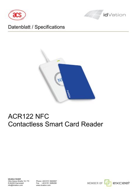
Datenblatt / Specifications<strong>ACR122</strong> <strong>NFC</strong><strong>Contactless</strong> <strong>Smart</strong> <strong>Card</strong> <strong>Reader</strong>idvation GmbHOtto-Hesse-Straße 19 / T5 Phone +49 6151 9926567D-64293 Darmstadt Fax +49 6151 3689296info@idvation.comwww.idvation.com
<strong>ACR122</strong>U Technical SpecificationsVersion 2.01Table of Contents1. Introduction ................................................................................................................................ 31.1. USB Interface ......................................................................................................................... 32. Implementation........................................................................................................................... 42.1. <strong>Smart</strong> <strong>Card</strong> <strong>Reader</strong> Interface Overview ................................................................................ 53. PICC Interface Description ........................................................................................................ 63.1. ATR Generation...................................................................................................................... 63.1.1. ATR format for ISO 14443 Part 3 PICCs ........................................................................... 63.1.2. ATR format for ISO 14443 Part 4 PICCs ........................................................................... 74. PICC Commands for General Purposes ................................................................................... 84.1. Get Data .................................................................................................................................. 85. PICC Commands (T=CL Emulation) for Mifare Classic Memory <strong>Card</strong>s ................................. 95.1. Load Authentication Keys ..................................................................................................... 95.2. Authentication ........................................................................................................................ 95.3. Read Binary Blocks ............................................................................................................. 135.4. Update Binary Blocks .......................................................................................................... 145.5. Value Block Related Commands ........................................................................................ 155.5.1. Value Block Operation ..................................................................................................... 155.5.2. Read Value Block ............................................................................................................ 165.5.3. Restore Value Block ........................................................................................................ 176. Pseudo-APDUs ......................................................................................................................... 186.1. Direct Transmit..................................................................................................................... 186.2. Bi-Color LED and Buzzer Control ....................................................................................... 196.3. Get the Firmware Version of the reader ............................................................................. 206.4. Get the PICC Operating Parameter ..................................................................................... 216.5. Set the PICC Operating Parameter ..................................................................................... 216.6. Set Timeout Parameter ........................................................................................................ 226.7. Set Buzzer Output Enable for <strong>Card</strong> Detection ................................................................... 227. Basic Program Flow for <strong>Contactless</strong> Applications ............................................................... 237.1. How to Access PC/SC-Compliant Tags (ISO 14443-4)? .................................................... 257.2. How to Access DESFire Tags (ISO 14443-4)? ................................................................... 267.3. How to Access FeliCa Tags (ISO 18092)? .......................................................................... 277.4. How to Access <strong>NFC</strong> Forum Type 1 Tags (ISO 18092), e.g. Jewel and Topaz Tags? ...... 288. Appendix E. Sample Codes for Setting the LED ................................................................... 30Page 2 of 33idvation GmbHOtto-Hesse-Straße 19 / T5 Phone +49 6151 9926567D-64293 Darmstadt Fax +49 6151 3689296info@idvation.comwww.idvation.com
<strong>ACR122</strong>U Technical SpecificationsVersion 2.011. IntroductionThe <strong>ACR122</strong>U is a PC-linked contactless smart card reader/writer used for accessing ISO 14443-4Type A and Type B, Mifare, ISO 18092 or <strong>NFC</strong>, and FeliCa tags. The <strong>ACR122</strong>U is PC/SC compliantso it is compatible with existing PC/SC applications. Furthermore, the standard Microsoft CC<strong>ID</strong> driveris used to simplify driver installation.The <strong>ACR122</strong>U serves as the intermediary device between the personal computer and the contactless tag via the USBinterface. The reader carries out the command from the PC whether the command is used in order to communicate with acontactless tag, or control the device peripherals (LED or buzzer).The <strong>ACR122</strong>U uses the PC/SC APDUs for contactless tags following the PC/SC Specification and makes use of pseudoAPDUs in sending commands for ISO 18092 tags and controlling the device peripherals. This document will discuss the<strong>ACR122</strong>U can be used in your smart card system.1.1. USB InterfaceThe <strong>ACR122</strong>U is connected to a computer through USB as specified in the USB Specification 1.1.The <strong>ACR122</strong>U is working in full-speed mode, i.e. 12 Mbps.Pin Signal Function1234VBUSD-D+GND+5 V power supply for the reader (Max. 200 mA, Normal 100 mA)Differential signal transmits data between <strong>ACR122</strong>U and PC.Differential signal transmits data between <strong>ACR122</strong>U and PC.Reference voltage level for power supplyTable 1 USB InterfacePage 3 of 33idvation GmbHOtto-Hesse-Straße 19 / T5 Phone +49 6151 9926567D-64293 Darmstadt Fax +49 6151 3689296info@idvation.comwww.idvation.com
<strong>ACR122</strong>U Technical SpecificationsVersion 2.012. Implementation2.1. Communication Flow Chart of <strong>ACR122</strong>UThe Standard Microsoft CC<strong>ID</strong> and PC/SC drivers are used; thus, no ACS drivers are required because the drivers arealready built inside the windows operating system. Your computer’s registry settings can also be modified to be able touse the full capabilities of the <strong>ACR122</strong>U <strong>NFC</strong> <strong>Reader</strong>. See Appendix 1 for more details.Figure 1: Communication Flow Chart of <strong>ACR122</strong>UPage 4 of 33idvation GmbHOtto-Hesse-Straße 19 / T5 Phone +49 6151 9926567D-64293 Darmstadt Fax +49 6151 3689296info@idvation.comwww.idvation.com
<strong>ACR122</strong>U Technical SpecificationsVersion 2.012.1. <strong>Smart</strong> <strong>Card</strong> <strong>Reader</strong> Interface OverviewClick on the “Device Manager” to find out the “<strong>ACR122</strong>U PICC Interface”. The standard Microsoft USB CC<strong>ID</strong> Driver isused.Figure 2: <strong>Smart</strong> <strong>Card</strong> <strong>Reader</strong> Interface on the Device ManagerPage 5 of 33idvation GmbHOtto-Hesse-Straße 19 / T5 Phone +49 6151 9926567D-64293 Darmstadt Fax +49 6151 3689296info@idvation.comwww.idvation.com
<strong>ACR122</strong>U Technical SpecificationsVersion 2.013. PICC Interface Description3.1. ATR GenerationIf the reader detects a PICC, an ATR will be sent to the PC/SC driver for identifying the PICC.3.1.1. ATR format for ISO 14443 Part 3 PICCsByteValue(Hex)Designation0 3B Initial HeaderDescription1 8N T0 Higher nibble 8 means: no TA1, TB1, TC1only TD1 is following.Lower nibble N is the number of historicalbytes (HistByte 0 to HistByte N-1)2 80 TD1 Higher nibble 8 means: no TA2, TB2, TC2only TD2 is following.Lower nibble 0 means T = 03 01 TD2 Higher nibble 0 means no TA3, TB3, TC3,TD3 following.Lower nibble 1 means T = 14To3+N80 T1 Category indicator byte, 80 means A statusindicator may be present in an optionalCOMPACT-TLV data object4FApplication identifier Presence Indicator0CLengthR<strong>ID</strong>TKRegistered Application Provider Identifier(R<strong>ID</strong>) # A0 00 00 03 06SSByte for standardC0 .. C1Bytes for card name00 00 00RFU RFU # 00 00 00 00004+N UU TCK Exclusive-oring of all the bytes T0 to TkTable 2: ATR format for ISO 14443 Part 3 PICCsExample: ATR for Mifare 1K = {3B 8F 80 01 80 4F 0C A0 00 00 03 06 03 00 01 00 0000 00 6A}ATRInitialHeader T0 TD1 TD2 T1 Tk Length R<strong>ID</strong> Standard<strong>Card</strong>Name RFU TCK3B 8F 80 01 80 4F 0CA0 000003 06Where: Length (YY) = 0CR<strong>ID</strong>= A0 00 00 03 06 (PC/SC Workgroup)Standard (SS) = 03 (ISO14443A, Part 3)<strong>Card</strong> Name (C0 .. C1) = [00 01] (Mifare 1K)03 00 0100 0000 00 6APage 6 of 33idvation GmbHOtto-Hesse-Straße 19 / T5 Phone +49 6151 9926567D-64293 Darmstadt Fax +49 6151 3689296info@idvation.comwww.idvation.com
<strong>ACR122</strong>U Technical SpecificationsVersion 2.01Where, <strong>Card</strong> Name (C0 .. C1)00 01: Mifare 1K00 02: Mifare 4K00 03: Mifare Ultralight00 26: Mifare Mini….F0 04: Topaz and JewelF0 11: FeliCa 212KF0 12: Felica 424K…FF [SAK]: Undefinedwww.acs.com.hk3.1.2. ATR format for ISO 14443 Part 4 PICCsByte ValueDesignationDescription(Hex)0 3B Initial Header1 8N T0 Higher nibble 8 means: no TA1, TB1, TC1only TD1 is following.Lower nibble N is the number of historicalbytes (HistByte 0 to HistByte N-1)2 80 TD1 Higher nibble 8 means: no TA2, TB2, TC2only TD2 is following.Lower nibble 0 means T = 03 01 TD2 Higher nibble 0 means no TA3, TB3, TC3,TD3 following.Lower nibble 1 means T = 14To3+Nxx T1TkHistorical Bytes:xxxxxxISO14443A:The historical bytes from ATS response. Referto the ISO14443-4 specification.ISO14443B:The higher layer response from the ATTRIBresponse (ATQB). Refer to the ISO14443-3specification.4+N UU TCK Exclusive-oring of all the bytes T0 to TkTable 3: ATR format for ISO 14443 Part 4 PICCsWe take for example, an ATR for DESFire, which is:DESFire (ATR) = 3B 86 80 01 06 75 77 81 02 80 00ATRInitial Header T0 TD1 TD2 ATSTD1 Tk TCK3B 86 80 01 06 75 77 81 02 80 00This ATR has 6 bytes of ATS, which is: [06 75 77 81 02 80]Note: Use the APDU “FF CA 01 00 00” to distinguish the ISO14443A-4 and ISO14443B-4PICCs, and retrieve the full ATS if available. The ATS is returned for ISO14443A-3 orISO14443B-3/4 PICCs.Another example would be the ATR for ST19XRC8E, which is:ST19XRC8E (ATR) = 3B 8C 80 01 50 12 23 45 56 12 53 54 4E 33 81 C3 55Page 7 of 33idvation GmbHOtto-Hesse-Straße 19 / T5 Phone +49 6151 9926567D-64293 Darmstadt Fax +49 6151 3689296info@idvation.comwww.idvation.com
<strong>ACR122</strong>U Technical SpecificationsVersion 2.01ATRInitial Header T0 TD1 TD2 ATQBT11 Tk TCK3B 86 80 01 50 12 23 45 56 12 53 54 4E 33 81 C3 55Since this card follows ISO 14443 Type B, the response would be ATQB which is 50 12 23 45 56 1253 54 4E 33 81 C3 is 12 bytes long with no CRC-BNote: You can refer to the ISO7816, ISO14443 and PC/SC standards for more detailsinfo@acs.com.hkwww.acs.com.hk4. PICC Commands for General Purposes4.1. Get DataThe “Get Data command” will return the serial number or ATS of the “connected PICC”.Get U<strong>ID</strong> APDU Format (5 Bytes)Command Class INS P1 P2 LeGet Data FF CA 0000 0001(Full Length)Get U<strong>ID</strong> Response Format (U<strong>ID</strong> + 2 Bytes) if P1 = 0x00ResponseResultU<strong>ID</strong>(LSB)Data OutU<strong>ID</strong>(MSB)SW1SW2Get ATS of a ISO 14443 A card (ATS + 2 Bytes) if P1 = 0x01ResponseData OutResult ATS SW1 SW2Response CodesResults SW1 SW2 MeaningSuccess 90 00 The operation completed successfully.Error 63 00 The operation failed.Error 6A 81 Function not supported.Example:1. To get the serial number of the “connected PICC”UINT8 GET_U<strong>ID</strong>[5]={0xFF, 0xCA, 0x00, 0x00, 0x04};2. To get the ATS of the “connected ISO 14443 A PICC”UINT8 GET_ATS[5]={0xFF, 0xCA, 0x01, 0x00, 0x04};Page 8 of 33idvation GmbHOtto-Hesse-Straße 19 / T5 Phone +49 6151 9926567D-64293 Darmstadt Fax +49 6151 3689296info@idvation.comwww.idvation.com
<strong>ACR122</strong>U Technical SpecificationsVersion 2.015. PICC Commands (T=CL Emulation) for Mifare Classic Memory <strong>Card</strong>s5.1. Load Authentication KeysThe “Load Authentication Keys command” will load the authentication keys into the reader. The authentication keys areused to authenticate the particular sector of the Mifare 1K/4K Memory <strong>Card</strong>. Volatile authentication key location isprovided. Load Authentication Keys APDU Format (11 Bytes)Command Class INS P1 P2 Lc Data InLoadAuthenticationKeysFF 82 KeyStructureKeyNumber06 Key(6 bytes)Where:Key Structure: 1 Byte.0x00 = Key is loaded into the reader volatile memory.Other = Reserved.Key Number: 1 Byte.0x00 ~ 0x01 = Key Location. The keys will disappear once the reader isdisconnected from the PC.Key: 6 Bytes.The key value loaded into the reader. E.g. {FF FF FF FF FF FF}Load Authentication Keys Response Format (2 Bytes)Response Data OutResult SW1 SW2Response CodesResults SW1 SW2 MeaningSuccess 90 00 The operation completed successfully.Error 63 00 The operation failed.Example:Load a key {FF FF FF FF FF FF} into the key location 0x00.APDU = {FF 82 00 00 06 FF FF FF FF FF FF}5.2. AuthenticationThe “Authentication command” uses the keys stored in the reader to do authentication with the Mifare1K/4K card (PICC). Two types of authentication keys are used: TYPE_A and TYPE_B.Load Authentication Keys APDU Format (6 Bytes) [ObsoleteCommand Class INS P1 P2 Lc Data InAuthentication FF 86 00 00 05 Authenticate Data BytesPage 9 of 33idvation GmbHOtto-Hesse-Straße 19 / T5 Phone +49 6151 9926567D-64293 Darmstadt Fax +49 6151 3689296info@idvation.comwww.idvation.com
<strong>ACR122</strong>U Technical SpecificationsVersion 2.01Authenticate Data Bytes (5 Bytes)Byte1 Byte 2 Byte 3 Byte 4 Byte 5Version 0x00 Block Key Type Key Number0x01NumberWhere:Block Number: 1 Byte. This is the memory block to be authenticated.Key Type: 1 Byte0x60 = Key is used as a TYPE A key for authentication.0x61 = Key is used as a TYPE B key for authentication.Key Number: 1 Byte0x00 ~ 0x01 = Key Location.Note: For Mifare 1K <strong>Card</strong>, it has totally 16 sectors and each sector consists of 4 consecutive blocks. E.g. Sector 0x00consists of Blocks {0x00, 0x01, 0x02 and 0x03}; Sector 0x01 consists of Blocks {0x04, 0x05, 0x06 and 0x07}; the lastsector 0x0F consists of Blocks {0x3C, 0x3D, 0x3E and 0x3F}.Once the authentication is done successfully, there is no need to do the authentication again if the blocks to be accessedbelong to the same sector. Please refer to the Mifare 1K/4K specification for more details.Load Authentication Keys Response Format (2 Bytes)Response Data OutResult SW1 SW2Response CodesResults SW1 SW2 MeaningSuccess 90 00 The operation completed successfully.Error 63 00 The operation failed.Page 10 of 33idvation GmbHOtto-Hesse-Straße 19 / T5 Phone +49 6151 9926567D-64293 Darmstadt Fax +49 6151 3689296info@idvation.comwww.idvation.com
<strong>ACR122</strong>U Technical SpecificationsVersion 2.01Memory MapSectors(Total 16 sectors. Each sectorconsists of 4 consecutiveblocks)Mifare 4K Memory MapData Blocks(3 blocks, 16 bytes per block)Trailer Block(1 block, 16 bytes)Sector 0 0x00 ~ 0x02 0x03Sector 1 0x04 ~ 0x06 0x07……Sector 14 0x38 ~ 0x0A 0x3BSector 15 0x3C ~ 0x3E 0x3FSectors(Total 32 sectors. Each sectorconsists of 4 consecutiveblocks)Data Blocks(3 blocks, 16 bytes per block)Sector 0 0x00 ~ 0x02 0x03Sector 1 0x04 ~ 0x06 0x07……Sector 30 0x78 ~ 0x7A 0x7BSector 31 0x7C ~ 0x7E 0x7FTrailer Block(1 block, 16 bytes)Sectors(Total 8 sectors. Each sectorconsists of 16 consecutiveblocks)Data Blocks(15 blocks, 16 bytes per block)Sector 32 0x80 ~ 0x8E 0x8FSector 33 0x90 ~ 0x9E 0x9F……Sector 38 0xE0 ~ 0xEE 0xEFSector 39 0xF0 ~ 0xFE 0xFFTrailer Block(1 block, 16 bytes)Page 11 of 33idvation GmbHOtto-Hesse-Straße 19 / T5 Phone +49 6151 9926567D-64293 Darmstadt Fax +49 6151 3689296info@idvation.comwww.idvation.com
<strong>ACR122</strong>U Technical SpecificationsVersion 2.01Mifare Ultralight Memory MapByte Number 0 1 2 3 PageSerial Number SN0 SN1 SN2 BCC0 0Serial Number SN3 SN4 SN5 SN6 1Internal / Lock BCC1 Internal Lock0 Lock1 2OTP OPT0 OPT1 OTP2 OTP3 3DataData0 Data1 Data2 Data3 4read/writeDataData4 Data5 Data6 Data7 5read/writeDataData8 Data9 Data10 Data11 6read/writeDataData12 Data13 Data14 Data15 7read/writeDataData16 Data17 Data18 Data19 8read/writeDataData20 Data21 Data22 Data23 9read/writeDataData24 Data25 Data26 Data27 10read/writeDataData28 Data29 Data30 Data31 11read/writeDataData32 Data33 Data34 Data35 12read/writeDataData36 Data37 Data38 Data39 13read/writeDataData40 Data41 Data42 Data43 14read/writeDataread/writeData44 Data45 Data46 Data47 15Example:1. To authenticate the Block 0x04 with a {TYPE A, key number 0x00}. For PC/SC V2.01, Obsolete.APDU = {FF 88 00 04 60 00};2. To authenticate the Block 0x04 with a {TYPE A, key number 0x00}. For PC/SC V2.07alaAPDU = {FF 86 00 00 05 01 00 04 60 00}Note:Mifare Ultralight does not need to do any authentication. The memory is free to access.Page 12 of 33idvation GmbHOtto-Hesse-Straße 19 / T5 Phone +49 6151 9926567D-64293 Darmstadt Fax +49 6151 3689296info@idvation.comwww.idvation.com
<strong>ACR122</strong>U Technical SpecificationsVersion 2.015.3. Read Binary BlocksThe “Read Binary Blocks command” is used for retrieving “data blocks” from the PICC. The data block/trailer block mustbe authenticated first.Read Binary APDU Format (5 Bytes)Command Class INS P1 P2 LeRead BinaryBlocksFF B0 00 Block Number Number of BytestoReadWhere: Block Number: 1 Byte. The block to be accessed Number of Bytes to Read: 1 Byte. MaximumRead Binary Block Response Format (N + 2 Bytes)ResponseData OutResult 0
<strong>ACR122</strong>U Technical SpecificationsVersion 2.015.4. Update Binary BlocksThe “Update Binary Blocks command” is used for writing “data blocks” into the PICC. The data block/trailer block must beauthenticated.Update Binary APDU Format (4 or 16 + 5 Bytes)Command Class INS P1 P2 Lc Data InUpdateBinaryBlocksFF D6 00 BlockNumberBlock DataWhere:NumberofBytestoUpdate4 Bytes forMifareUltralightor16 Bytes forMifare 1K/4KBlock Number: 1 Byte. The starting block to be updated.Number of Bytes to Update: 1 Byte.o 16 bytes for Mifare 1K/4Ko 4 bytes for Mifare Ultralight.Block Data: 4 or 16 BytesThe data to be written into the binary block/blocks.Response CodesResults SW1 SW2 MeaningSuccess 90 00.The operation completedsuccessfullyError 63 00 The operation failed.Example:1. Update the binary block 0x04 of Mifare 1K/4K with Data {00 01 .. 0F}APDU = {FF D6 00 04 10 00 01 02 03 04 05 06 07 08 09 0A 0B 0C 0D 0E 0F}2. Update the binary block 0x04 of Mifare Ultralight with Data {00 01 02 03}APDU = {FF D6 00 04 04 00 01 02 03}Page 14 of 33idvation GmbHOtto-Hesse-Straße 19 / T5 Phone +49 6151 9926567D-64293 Darmstadt Fax +49 6151 3689296info@idvation.comwww.idvation.com
<strong>ACR122</strong>U Technical SpecificationsVersion 2.015.5. Value Block Related CommandsThe data block can be used as value block for implementing value-based applications.5.5.1. Value Block OperationThe “Value Block Operation command” is used for manipulating value-based transactions. E.g.Increment a value of the value block etc.Value Block Operation APDU Format (10 Bytes)Command Class INS P1 P2 Lc Data InValueBlockOperationFF D7 00 BlockNumber05 VB_OP VB_Value(4 Bytes){MSB ..LSB}Where:Block Number: 1 Byte. The value block to be manipulated.VB_OP: 1 Byte.0x00 = Store the VB_Value into the block. The block will then be converted to a valueblock.0x01 = Increment the value of the value block by the VB_Value. This command is only valid for value block.0x02 = Decrement the value of the value block by the VB_Value. This command is only valid for value block.VB_Value: 4 Bytes. The value used for value manipulation. The value is a signed long integer (4 bytes).Example 1: Decimal –4 = {0xFF, 0xFF, 0xFF, 0xFC}VB_ValueMSBLSBFF FF FF FCExample 2: Decimal 1 = {0x00, 0x00, 0x00, 0x01}VB_ValueMSBLSB00 00 00 01Value Block Operation Response Format (2 Bytes)Response Data OutResult SW1 SW2Response CodesResults SW1 SW2 MeaningSuccess 90 00 The operation completedsuccessfully.Error 63 00 The operation failed.Page 15 of 33idvation GmbHOtto-Hesse-Straße 19 / T5 Phone +49 6151 9926567D-64293 Darmstadt Fax +49 6151 3689296info@idvation.comwww.idvation.com
<strong>ACR122</strong>U Technical SpecificationsVersion 2.015.5.2. Read Value BlockThe “Read Value Block command” is used for retrieving the value from the value block. Thiscommand is only valid for value block.Read Value Block APDU Format (5 Bytes)Command Class INS P1 P2 LeRead Value Block FF B1 00 Block Number 04Where:Block Number: 1 Byte. The value block to be accessed.Read Value Block Response Format (4 + 2 Bytes)ResponseResultData OutValue{MSB .. LSB}SW1SW2Where:Value: 4 Bytes. The value returned from the card. The value is a signed long integer (4bytes).Example 1: Decimal –4 = {0xFF, 0xFF, 0xFF, 0xFC}ValueMSBLSBFF FF FF FCExample 2: Decimal 1 = {0x00, 0x00, 0x00, 0x01}ValueMSBLSB00 00 00 01Response CodesResults SW1 SW2 MeaningSuccess 90 00 The operation completedsuccessfully.Error 63 00 The operation failed.Page 16 of 33idvation GmbHOtto-Hesse-Straße 19 / T5 Phone +49 6151 9926567D-64293 Darmstadt Fax +49 6151 3689296info@idvation.comwww.idvation.com
<strong>ACR122</strong>U Technical SpecificationsVersion 2.015.5.3. Restore Value BlockThe “Restore Value Block command” is used to copy a value from a value block to another valueblock.Restore Value Block APDU Format (7 Bytes)Command Class INS P1 P2 Lc Data InRestoreValue BlockWhere:FF D7 00 SourceBlockNumber02 03 TargetBlockNumber Source Block Number: 1 Byte. The value of the source value block will be copied to thetarget value block. Target Block Number: 1 Byte. The value block to be restored. The source and target valueblocks must be in the same sector.Restore Value Block Response Format (2 Bytes)Response Data OutResult SW1 SW2Response CodesResults SW1 SW2 MeaningSuccess 90 00 The operation completedsuccessfully.Error 63 00 The operation failed.Example:1. Store a value “1” into block 0x05APDU = {FF D7 00 05 05 00 00 00 00 01}Answer: 90 00.acs.com.hk2. Read the value block 0x05APDU = {FF B1 00 05 00}Answer: 00 00 00 01 90 00 [9000]3. Copy the value from value block 0x05 to value block 0x06APDU = {FF D7 00 05 02 03 06}Answer: 90 00 [9000]4. Increment the value block 0x05 by “5”APDU = {FF D7 00 05 05 01 00 00 00 05}Answer: 90 00 [9000]info@acs.com.hkPage 17 of 33idvation GmbHOtto-Hesse-Straße 19 / T5 Phone +49 6151 9926567D-64293 Darmstadt Fax +49 6151 3689296info@idvation.comwww.idvation.com
<strong>ACR122</strong>U Technical SpecificationsVersion 2.01www.acs.com.hk6. Pseudo-APDUsPseudo-APDUs are used for the following:Exchanging Data with Non-PC/SC Compliant Tags.Retrieving and setting the reader parameters.The Pseudo-APDUs can be sent through the “<strong>ACR122</strong>U PICC Interface” if the tag is already connected.Or the Pseudo-APDUs can be sent by using “Escape Command” if the tag is not presented yet.6.1. Direct TransmitThis is the Payload to be sent to the tag or reader.Direct Transmit Command Format (Length of the Payload + 5 Bytes)Command Class INS P1 P2 Lc Data InDirectTransmit0xFF 0x00 0x00 0x00 NumberofBytesto sendPayloadWhere:Lc: 1 Byte. Number of Bytes to SendMaximum 255 bytesData In: ResponseDirect Transmit Response FormatResponseDirect TransmitData OutResponse DataPage 18 of 33idvation GmbHOtto-Hesse-Straße 19 / T5 Phone +49 6151 9926567D-64293 Darmstadt Fax +49 6151 3689296info@idvation.comwww.idvation.com
<strong>ACR122</strong>U Technical SpecificationsVersion 2.016.2. Bi-Color LED and Buzzer ControlThis APDU is used to control the states of the Bi-Color LED and Buzzer.Bi-Color LED and Buzzer Control Command Format (9 Bytes)Command Class INS P1 P2 Lc Data In(4 Bytes)Bi-Colorand BuzzerLEDControl0xFF 0x00 0x40 LEDStateControl0x04 BlinkingDurationControlP2: LED State ControlCMD Item DescriptionBit 0 Final Red LED State 1 = On; 0 = OffBit 1 Final Green LED State 1 = On; 0 = OffBit 2 Red LED State Mask 1 = Update the State0 = No changeBit 3 Green LED State Mask 1 = Update the State0 = No changeBit 4 Initial Red LED Blinking State 1 = On; 0 = OffBit 5 Initial Green LED Blinking State 1 = On; 0 = OffBit 6 Red LED Blinking Mask 1 = Blink0 = Not BlinkBit 7 Green LED Blinking Mask 1 = Blink0 = Not BlinkData In: Blinking Duration ControlBi-Color LED Blinking Duration Control Format (4 Bytes)Byte 0 Byte 1 Byte 2 Byte 3T1 DurationInitial Blinking State(Unit = 100ms)T2 DurationToggle Blinking State(Unit = 100ms)Number ofrepetitionLink to BuzzerWhere:Byte 3: Link to Buzzer. Control the buzzer state during the LED Blinking.0x00: The buzzer will not turn on0x01: The buzzer will turn on during the T1 Duration0x02: The buzzer will turn on during the T2 Duration0x03: The buzzer will turn on during the T1 and T2 Duration.Page 19 of 33idvation GmbHOtto-Hesse-Straße 19 / T5 Phone +49 6151 9926567D-64293 Darmstadt Fax +49 6151 3689296info@idvation.comwww.idvation.com
<strong>ACR122</strong>U Technical SpecificationsVersion 2.01Data Out: SW1 SW2. Status Code returned by the reader.Results SW1 SW2 MeaningSuccess 90 Current LEDStateThe operation completedsuccessfully.Error 63 00 The operation failed.Status Item DescriptionBit 0 Current Red LED 1 = On; 0 = OffBit 1 Current Green LED 1 = On; 0 = OffBits 2 – 7ReservedTable 4 Current LED State (1 Byte)Note:A. The LED State operation will be performed after the LED Blinking operation is completed.B. The LED will not be changed if the corresponding LED Mask is not enabled.C. The LED will not be blinking if the corresponding LED Blinking Mask is not enabled. Also,the number of repetition must be greater than zero.D. T1 and T2 duration parameters are used for controlling the duty cycle of LED blinking and Buzzer Turn-On duration.For example, if T1=1 and T2=1, the duty cycle = 50%. #Duty Cycle = T1 / (T1 + T2).E. To control the buzzer only, just set the P2 “LED State Control” to zero.F. The make the buzzer operating, the “number of repetition” must greater than zero.G. To control the LED only, just set the parameter “Link to Buzzer” to zero.6.3. Get the Firmware Version of the readerThis is used to retrieve the firmware version of the reader.Command Format (5 Bytes)Command Class INS P1 P2 LeGetFirmwareVersion0xFF 0x00 0x48 0x00 0x00Response Format (10 Bytes)ResponseResultData OutFirmware VersionE.g. Response = 41 43 52 31 32 32 55 32 30 31 (Hex) = <strong>ACR122</strong>U201 (ASCII)Page 20 of 33idvation GmbHOtto-Hesse-Straße 19 / T5 Phone +49 6151 9926567D-64293 Darmstadt Fax +49 6151 3689296info@idvation.comwww.idvation.com
<strong>ACR122</strong>U Technical SpecificationsVersion 2.016.4. Get the PICC Operating ParameterThis is used to retrieve the PICC Operating Parameter of the reader.Command Format (5 Bytes)Command Class INS P1 P2 LeGet PICCOperatingParameter0xFF 0x00 0x50 0x00 0x00Response Format (1Byte)ResponseResultData OutPICC Operating Parameter6.5. Set the PICC Operating ParameterThis is used to set the PICC Operating Parameter of the reader.Command Format (5 Bytes)Command Class INS P1 P2 LeSet PICCOperatingParameter0xFF 0x00 0x51 New PICCOperatingParameter0x00Response Format (1 Byte)ResponseResultData OutPICC OperatingParameterBit Parameter Description Option7 Auto PICC Polling To enable the PICC Polling 1 = Enable0 = Disable6 Auto ATS Generation To issue ATS Requestwhenever anISO14443-4 Type A tag isactivated1 = Enable0 = Disable5 Polling Interval To set the time intervalbetweensuccessive PICC Polling.1 = 250 ms0 = 500 msPage 21 of 33idvation GmbHOtto-Hesse-Straße 19 / T5 Phone +49 6151 9926567D-64293 Darmstadt Fax +49 6151 3689296info@idvation.comwww.idvation.com
<strong>ACR122</strong>U Technical SpecificationsVersion 2.014 FeliCa 424K1 = Detect0 = Skip3 FeliCa 212K 1 = Detect0 = Skip2 TopazThe Tag Types to be detected1 = Detectduring PICC Polling.0 = Skip1 ISO14443 Type B 1 = Detect0 = Skip0 ISO14443 Type A#To detect the MifareTags, the Auto ATSGeneration must bedisabled first.1 = Detect0 = Skip6.6. Set Timeout ParameterThis is used to set the Time out Parameter of the contactless chip response time.Command Format (5 Bytes)Command Class INS P1 P2 LeSet TimeoutParameter0xFF 0x00 0x41 TimeoutParameter(Unit: 5 sec.)0x00Where:P2: Timeout Parameter. 0x00: No Timeout check 0x01 – 0xFE: Timeout with 5 second unit 0xFF: Wait until the contactless chip respondsResponse Format (8 Bytes)Results SW1 SW2 MeaningSuccess 90 00 The operation completedsuccessfully.Error 63 00 The operation failed.6.7. Set Buzzer Output Enable for <strong>Card</strong> DetectionThis is used to set the buzzer output during card detection. The default output is ON.Command Format (5 Bytes)Command Class INS P1 P2 LeSet BuzzerOutput for<strong>Card</strong>Detection0xFF 0x00 0x52 PollBuzzStatus 0x00Page 22 of 33idvation GmbHOtto-Hesse-Straße 19 / T5 Phone +49 6151 9926567D-64293 Darmstadt Fax +49 6151 3689296info@idvation.comwww.idvation.com
<strong>ACR122</strong>U Technical SpecificationsVersion 2.01Where:P2: PollBuzzStatus. 0x00: Buzzer will NOT turn ON when a card is detected 0xFF: Buzzer will turn ON when a card is detectedResponse Format (8 Bytes)Results SW1 SW2 MeaningSuccess 90 00 The operation completedsuccessfully.Error 63 00 The operation failed.7. Basic Program Flow for <strong>Contactless</strong> ApplicationsStep 0. Start the application. The reader will do the PICC Polling and scan for tags continuously.Once the tag is found and detected, the corresponding ATR will be sent to the PC. You mustmake sure that the PC/SC Escape Command has been set. See Appendix 1 for moredetails.Step 1. The first thing is to connect the “<strong>ACR122</strong>U PICC Interface”.Step 2. Access the PICC by sending APDU commands.::Step N. Disconnect the “<strong>ACR122</strong>U PICC Interface”. Shut down the application.NOTE:1. The antenna can be switched off in order to save the power.o Turn off the antenna power: FF 00 00 00 04 D4 32 01 00o Turn on the antenna power: FF 00 00 00 04 D4 32 01 012. Standard and Non-Standard APDUs Handling.o PICCs that use Standard APDUs: ISO14443-4 Type A and B, Mifare .. etco PICCs that use Non-Standard APDUs: FeliCa, Topaz .. etc.Page 23 of 33idvation GmbHOtto-Hesse-Straße 19 / T5 Phone +49 6151 9926567D-64293 Darmstadt Fax +49 6151 3689296info@idvation.comwww.idvation.com
<strong>ACR122</strong>U Technical SpecificationsVersion 2.01Figure 2 Basic Program Flow for <strong>Contactless</strong> Applicationswww.acs.com.hk1) For the <strong>ACR122</strong>U PICC Interface, ISO7816 T=1 protocol is used.o PC <strong>Reader</strong>: Issue an APDU to the reader.o <strong>Reader</strong> PC: The response data is returned.Page 24 of 33idvation GmbHOtto-Hesse-Straße 19 / T5 Phone +49 6151 9926567D-64293 Darmstadt Fax +49 6151 3689296info@idvation.comwww.idvation.com
<strong>ACR122</strong>U Technical SpecificationsVersion 2.017.1. How to Access PC/SC-Compliant Tags (ISO 14443-4)?Basically, all ISO 14443-4 compliant cards (PICCs) would understand the ISO 7816-4 APDUs. The <strong>ACR122</strong>U <strong>Reader</strong> justhas to communicate with the ISO 14443-4 compliant cards through exchangingISO 7816-4 APDUs and Responses. <strong>ACR122</strong>U will handle the ISO 14443 Parts 1-4 Protocols internally.Mifare 1K, 4K, MINI and Ultralight tags are supported through the T=CL emulation. Just simply treat the Mifare tags asstandard ISO 14443-4 tags. For more information, please refer to topic “PICC Commands for Mifare Classic MemoryTags”.ISO 7816-4 APDU FormatCommand Class INS P1 P2 Lc DataInISO 7816LengthPart 4of theCommandDataInLeExpectedlengthof theResponseDataISO 7816-4 Response Format (Data + 2 Bytes)ResponseData OutResult Response Data SW1 SW2Response CodesResults SW1 SW2 MeaningSuccess 90 00 The operation completedsuccessfully.Error 63 00 The operation failed.Typical sequence may be:- Present the Tag and Connect the PICC Interface- Read / Update the memory of the tagStep 1) Connect the TagStep 2) Send an APDU, Get Challenge.> 1A F7 F3 1B CD 2B A9 58 [90 00]Note: For ISO14443-4 Type A tags, the ATS can be obtained by using the APDU “FF CA 0000 01”Page 25 of 33idvation GmbHOtto-Hesse-Straße 19 / T5 Phone +49 6151 9926567D-64293 Darmstadt Fax +49 6151 3689296info@idvation.comwww.idvation.com
<strong>ACR122</strong>U Technical SpecificationsVersion 2.017.2. How to Access DESFire Tags (ISO 14443-4)?DESFire supports ISO 7816-4 APDU Wrapping and Native modes. Once the DESFire Tag is activated, the first APDUsent to the DESFire Tag will determine the “Command Mode”. If the first APDU is “Native Mode”, the rest of the APDUsmust be in “Native Mode” format. Similarly, if the first APDU is “ISO 7816-4 APDU Wrapping Mode”, the rest of the APDUsmust be in “ISO 7816-4 APDU Wrapping Mode” format.Example 1: DESFire ISO 7816-4 APDU WrappingTo read 8 bytes random number from an ISO 14443-4 Type A PICC (DESFire)APDU = {90 0A 00 00 01 00 00}Class = 0x90; INS = 0x0A (DESFire Instruction); P1 = 0x00; P2 = 0x00Lc = 0x01; Data In = 0x00; Le = 0x00 (Le = 0x00 for maximum length)Answer: 7B 18 92 9D 9A 25 05 21 [$91AF]The Status Code [91 AF] is defined in DESFire specification. Please refer to the DESFire specification for moredetails.Example 2: DESFire Frame Level Chaining (ISO 7816 wrapping mode)In this example, the application has to do the “Frame Level Chaining”. To get the version ofthe DESFire card.Step 1: Send an APDU {90 60 00 00 00} to get the first frame. INS=0x60Answer: 04 01 01 00 02 18 05 91 AF [$91AF]Step 2: Send an APDU {90 AF 00 00 00} to get the second frame. INS=0xAFAnswer: 04 01 01 00 06 18 05 91 AF [$91AF]Step 3: Send an APDU {90 AF 00 00 00} to get the last frame. INS=0xAFAnswer: 04 52 5A 19 B2 1B 80 8E 36 54 4D 40 26 04 91 00 [$9100]Example 3: DESFire Native CommandWe can send Native DESFire Commands to the reader without ISO 7816 wrapping if we findthat the Native DESFire Commands are easier to handle.To read 8 bytes random number from an ISO 14443-4 Type A PICC (DESFire)APDU = {0A 00}Answer: AF 25 9C 65 0C 87 65 1D D7[$1DD7]In which, the first byte “AF” is the status code returned by the DESFire <strong>Card</strong>.The Data inside the blanket [$1DD7] can simply be ignored by the application.Example 4: DESFire Frame Level Chaining (Native Mode)In this example, the application has to do the “Frame Level Chaining”.To get the version of the DESFire card.Step 1: Send an APDU {60} to get the first frame. INS=0x60Answer: AF 04 01 01 00 02 18 05[$1805]Step 2: Send an APDU {AF} to get the second frame. INS=0xAFAnswer: AF 04 01 01 00 06 18 05[$1805]Step 3: Send an APDU {AF} to get the last frame. INS=0xAFAnswer: 00 04 52 5A 19 B2 1B 80 8E 36 54 4D 40 26 04[$2604]Note: In DESFire Native Mode, the status code [90 00] will not be added to the response ifthe response length is greater than 1. If the response length is less than 2, the status code[90 00] will be added in order to meet the requirement of PC/SC. The minimum responselength is 2.Page 26 of 33idvation GmbHOtto-Hesse-Straße 19 / T5 Phone +49 6151 9926567D-64293 Darmstadt Fax +49 6151 3689296info@idvation.comwww.idvation.com
<strong>ACR122</strong>U Technical SpecificationsVersion 2.017.3. How to Access FeliCa Tags (ISO 18092)?Typical sequence may be:- Present the FeliCa Tag and Connect the PICC Interface- Read / Update the memory of the tagStep 1) Connect the TagThe ATR = 3B 8F 80 01 80 4F 0C A0 00 00 03 06 03 F0 11 00 00 00 00 8AIn which,F0 11 = FeliCa 212KStep 2) Read the memory block without using Pseudo APDU.> 1D 07 [8-byte <strong>NFC</strong> <strong>ID</strong>] 00 00 01 00 AA 55 AA 55 AA 55 AA 55 AA 55 AA 55 AA55 AA [90 00]OrStep 2) Read the memory block using Pseudo APDU.> D5 41 00 1D 07 [8-byte <strong>NFC</strong> <strong>ID</strong>] 00 00 01 00 AA 55 AA 55 AA 55 AA 55 AA 55AA 55 AA 55 AA [90 00]In which, D5 41 00 is the Data Exchange ResponseNote:The <strong>NFC</strong> <strong>ID</strong> can be obtained by using the APDU “FF CA 00 00 00”Please refer to the FeliCa specification for more detailed information.Page 27 of 33idvation GmbHOtto-Hesse-Straße 19 / T5 Phone +49 6151 9926567D-64293 Darmstadt Fax +49 6151 3689296info@idvation.comwww.idvation.com
<strong>ACR122</strong>U Technical SpecificationsVersion 2.017.4. How to Access <strong>NFC</strong> Forum Type 1 Tags (ISO 18092), e.g. Jewel and TopazTags?Typical sequence may be: Present the Topaz Tag and Connect the PICC Interface Read / Update the memory of the tagStep 1) Connect the TagThe ATR = 3B 8F 80 01 80 4F 0C A0 00 00 03 06 03 F0 04 00 00 00 00 9FIn which, F0 04 = TopazStep 2) Read the memory address 08 (Block 1: Byte-0) without using Pseudo APDU> 18 [90 00]In which, Response Data = 18Orwww.acs.com.hkStep 2) Read the memory address 08 (Block 1: Byte-0) using Pseudo APDU> D5 41 00 18 [90 00]In which, Response Data = 18Tip: To read all the memory content of the tag> 11 48 18 26 .. 00 [90 00]Step 3) Update the memory address 08(Block 1: Byte-0)with the data FF> FF [90 00]In which, Response Data = FFPage 28 of 33idvation GmbHOtto-Hesse-Straße 19 / T5 Phone +49 6151 9926567D-64293 Darmstadt Fax +49 6151 3689296info@idvation.comwww.idvation.com
<strong>ACR122</strong>U Technical SpecificationsVersion 2.01Topaz Memory Map.Memory Address = Block No * 8 + Byte NoE.g. Memory Address 08 (hex) = 1 x 8 + 0 = Block 1: Byte-0 = Data0E.g. Memory Address 10 (hex) = 2 x 8 + 0 = Block 2: Byte-0 = Data8Page 29 of 33idvation GmbHOtto-Hesse-Straße 19 / T5 Phone +49 6151 9926567D-64293 Darmstadt Fax +49 6151 3689296info@idvation.comwww.idvation.com
<strong>ACR122</strong>U Technical SpecificationsVersion 2.018. Appendix E. Sample Codes for Setting the LED• Example 1: To read the existing LED State// Assume both Red and Green LEDs are OFF initially //// Not link to the buzzer //APDU = “FF 00 40 00 04 00 00 00 00”Response = “90 00”. RED and Green LEDs are OFF.• Example 2: To turn on RED and Green Color LEDs// Assume both Red and Green LEDs are OFF initially //// Not link to the buzzer //APDU = “FF 00 40 0F 04 00 00 00 00”Response = “90 03”. RED and Green LEDs are ON,To turn off both RED and Green LEDs, APDU = “FF 00 40 0C 04 00 00 00 00”Example 3: To turn off the RED Color LED only, and leave the Green Color LED unchanged// Assume both Red and Green LEDs are ON initially //// Not link to the buzzer //APDU = “FF 00 40 04 04 00 00 00 00”Response = “90 02”. Green LED is not changed (ON); Red LED is OFF,Example 4: To turn on the Red LED for 2 sec. After that, resume to the initial state// Assume the Red LED is initially OFF, while the Green LED is initially ON. //// The Red LED and buzzer will turn on during the T1 duration, while the Green LED will turn off duringthe T1 duration. //Page 30 of 33idvation GmbHOtto-Hesse-Straße 19 / T5 Phone +49 6151 9926567D-64293 Darmstadt Fax +49 6151 3689296info@idvation.comwww.idvation.com
<strong>ACR122</strong>U Technical SpecificationsVersion 2.011Hz = 1000ms Time Interval = 500ms ON + 500 ms OFFT1 Duration = 2000ms = 0x14T2 Duration = 0ms = 0x00Number of repetition = 0x01Link to Buzzer = 0x01APDU = “FF 00 40 50 04 14 00 01 01”Response = “90 02”Example 5: To make the Red LED blink at 1Hz , three times. After which, it resumes to initial state// Assume the Red LED is initially OFF, while the Green LED is initially ON. //// The Initial Red LED Blinking State is ON. Only the Red LED will be blinking.// The buzzer will turn on during the T1 duration, while the Green LED will turn off during both the T1 and T2 duration.// After the blinking, the Green LED will turn ON. The Red LED will resume to the initial state after theblinking //1Hz = 1000ms Time Interval = 500ms ON + 500 ms OFFT1 Duration = 500ms = 0x05T2 Duration = 500ms = 0x05Number of repetition = 0x03Link to Buzzer = 0x01APDU = “FF 00 40 50 04 05 05 03 01”Page 31 of 33idvation GmbHOtto-Hesse-Straße 19 / T5 Phone +49 6151 9926567D-64293 Darmstadt Fax +49 6151 3689296info@idvation.comwww.idvation.com
<strong>ACR122</strong>U Technical SpecificationsVersion 2.01Example 6: To make the Red and Green LEDs blink at 1Hz three times// Assume both the Red and Green LEDs are initially OFF. //// Both Initial Red and Green Blinking States are ON //// The buzzer will turn on during both the T1 and T2 duration//1Hz = 1000ms Time Interval = 500ms ON + 500 ms OFFT1 Duration = 500ms = 0x05T2 Duration = 500ms = 0x05Number of repetition = 0x03Link to Buzzer = 0x03APDU = “FF 00 40 F0 04 05 05 03 03”Response = “90 00”Page 32 of 33idvation GmbHOtto-Hesse-Straße 19 / T5 Phone +49 6151 9926567D-64293 Darmstadt Fax +49 6151 3689296info@idvation.comwww.idvation.com
<strong>ACR122</strong>U Technical SpecificationsVersion 2.01Example 7: To make Red and Green LED blink in turns at 1Hz three times// Assume both Red and Green LEDs are initially OFF. //// The Initial Red Blinking State is ON; The Initial Green Blinking States is OFF //// The buzzer will turn on during the T1 duration//1Hz = 1000ms Time Interval = 500ms ON + 500 ms OFFT1 Duration = 500ms = 0x05T2 Duration = 500ms = 0x05Number of repetition = 0x03Link to Buzzer = 0x01APDU = “FF 00 40 D0 04 05 05 03 01”; Response = “90 00”Page 33 of 33idvation GmbHOtto-Hesse-Straße 19 / T5 Phone +49 6151 9926567D-64293 Darmstadt Fax +49 6151 3689296info@idvation.comwww.idvation.com