dBTrig User Manual - Standard & Expert Mode - Acoustic1
dBTrig User Manual - Standard & Expert Mode - Acoustic1
dBTrig User Manual - Standard & Expert Mode - Acoustic1

You also want an ePaper? Increase the reach of your titles
YUMPU automatically turns print PDFs into web optimized ePapers that Google loves.
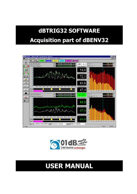
Copyright ©dBTRIG32ACQUISITION PART OF dBENV32dBTRIG32 acquisition software - <strong>User</strong> manual<strong>Standard</strong> and <strong>Expert</strong> modes infogb@01dB.com www.01dB.com01dB Head Office200, chemin des OrmeauxF-69578 Limonest CedexFRANCE +33 4 72 52 48 00 +33 4 72 52 47 4701dB Italia s.r.l.Via Antoniana, 27835011 CampodarsegoITALY01dB Inc.31 Jordan StreetP.O. Box 796Skaneateles NY 13152USA01dB do BrasilRua Domingos de Morais 2102Sala 11 – 1 Andar – Vila Mariana04036-000 Saõ PauloBRAZIL01dB Asia PacificNo. 9 Jalan USJ10/1D47620 Petaling JayaSelangorMALAYSIA +39 049 92 00 966 +39 049 92 01 239 +1 315 685 3141 +1 315 685 3194 +55 11 5579 6460 +55 11 5579 6610 +60 3 563 22 633 +60 3 563 18 633The specifications are subject to change without notice.SYMPHONIE® is a registered trademark of 01dBMICROSOFT® is a registered trademark of Microsoft CorporationWindows 98, Windows 2000, NT and XP are trademarks of Microsoft CorporationP83MAN20-03 NOT1103gb_dBTRIG32_4.0_NE_manual_03.doc – Updated on: October 2003
DBTRIG32 ACQUISITION SOFTWARE : USER MANUAL - STANDARD & EXPERT MODESTABLE OF CONTENTS 11. DESCRIPTION OF A 01DB PC-BASED MEASUREMENT CHAIN____________________________ 91.1. INTRODUCTION ______________________________________________________________________ 91.2. GENERAL DESCRIPTION_______________________________________________________________ 101.3. ENVIRONMENTAL NOISE APPLICATIONS __________________________________________________ 112. MEASURING WITH DBTRIG32 ________________________________________________________ 132.1. PRINCIPLE OF MEASUREMENT __________________________________________________________ 132.2. NEW FUNCTIONS AND OPTIONAL MODULES________________________________________________ 142.3. USER LEVEL OF THE SOFTWARE ________________________________________________________ 162.4. MODES OF OPERATIONS ______________________________________________________________ 172.4.1. Inactive mode__________________________________________________________________ 172.4.2. Play mode ____________________________________________________________________ 172.4.3. Record mode __________________________________________________________________ 173. MEASUREMENT HARDWARE CONFIGURATION_______________________________________ 194. MEASUREMENT CONFIGURATION FILES _____________________________________________ 215. MEASUREMENT CHAIN CALIBRATION _______________________________________________ 236. DBTRIG32 MEASUREMENT WINDOW _________________________________________________ 256.1. MEASUREMENT WINDOW COMMAND BAR_________________________________________________ 266.2. MEASUREMENT WINDOW HORIZONTAL TOOLBAR___________________________________________ 266.3. MEASUREMENT WINDOW STATUS BAR ___________________________________________________ 276.4. TIME HISTORY PLOT _________________________________________________________________ 276.5. SPECTRUM PLOT ____________________________________________________________________ 286.6. DEFINITION OF AUXILIARY EVENT (EXPERT MODE)__________________________________________ 287. MEASUREMENT PARAMETERS (SET-UP)______________________________________________ 297.1. ACQUISITION PARAMETERS____________________________________________________________ 297.1.1. Overall tab ____________________________________________________________________ 297.1.2. Channel(s) tab _________________________________________________________________ 307.1.3. Advanced tab __________________________________________________________________ 317.2. STORAGE PARAMETERS (STANDARD MODE) _______________________________________________ 327.2.1. Overall tab ____________________________________________________________________ 327.2.2. Channels tab __________________________________________________________________ 337.2.3. Audio event tab ________________________________________________________________ 347.3. STORAGE PARAMETERS (EXPERT MODE) __________________________________________________ 357.3.1. Overall tab ____________________________________________________________________ 357.3.2. Channels tab __________________________________________________________________ 367.3.3. Audio event tab ________________________________________________________________ 377.3.4. Spectrum event tab______________________________________________________________ 387.4. SOURCE CODING PARAMETERS (STANDARD MODE)__________________________________________ 397.4.1. Definition tab __________________________________________________________________ 397.5. SOURCE CODING PARAMETERS (EXPERT MODE) ____________________________________________ 407.5.1. Definition tab __________________________________________________________________ 407.5.2. Code event tab _________________________________________________________________ 417.6. ADVANCED PARAMETERS _____________________________________________________________ 427.6.1. Automatic gain shift tab__________________________________________________________ 427.6.2. Automatic calibration tab ________________________________________________________ 431 Important Notice: Because this software package is modular in structure, some of the functionsdescribed in this manual may not be available in your copy of the software. To upgrade your version withoptional modules, contact your 01dB agent.TABLE OF CONTENTS PAGE 5
DBTRIG32 ACQUISITION SOFTWARE : USER MANUAL - STANDARD & EXPERT MODES7.6.3. Alarm event tab (expert mode) _____________________________________________________ 437.7. DEFINITION OF STORAGE PERIODS _______________________________________________________ 447.7.1. 24 hour cycle___________________________________________________________________ 447.7.2. 7 day cycle ____________________________________________________________________ 457.8. EVENT TRIGGERS (STANDARD MODE) ____________________________________________________ 467.8.1. Periods of activity of a trigger _____________________________________________________ 477.8.2. Threshold trigger conditions ______________________________________________________ 487.8.2.1. Example of absolute threshold__________________________________________________________ 487.8.2.2. Example of relative threshold __________________________________________________________ 497.8.2.3. Example of absolute threshold : particular case ____________________________________________ 497.8.3. Clock trigger condition___________________________________________________________ 497.9. EVENT TRIGGERS (EXPERT MODE) _______________________________________________________ 507.9.1. Periods of activity of a trigger _____________________________________________________ 517.9.2. Threshold trigger conditions ______________________________________________________ 527.9.2.1. Example of absolute threshold condition__________________________________________________ 537.9.2.2. Example of relative threshold condition __________________________________________________ 537.9.2.3. Example of trigger with two threshold conditions___________________________________________ 537.9.3. Clock trigger condition___________________________________________________________ 547.10. DYNAMIC RANGE PARAMETERS _______________________________________________________ 547.11. SELECTIVE CONFIGURATION TASKS ____________________________________________________ 557.11.1. Conversion units and references management (from a physical unit to a dB level)_____________ 557.11.2. Display line spectra _____________________________________________________________ 567.11.3. Definition of sources' names_______________________________________________________ 568. MEASUREMENT WINDOW DISPLAY PARAMETERS ____________________________________ 578.1. COMMAND DISPLAY / LAYOUT _________________________________________________________ 578.2. COMMAND DISPLAY / TIME HISTORY ____________________________________________________ 588.3. COMMAND DISPLAY / DIGITAL INDICATORS_______________________________________________ 598.4. COMMAND DISPLAY / SPECTRUM _______________________________________________________ 598.5. COMMAND PREFERENCES / COLOURS ____________________________________________________ 608.6. COMMAND PREFERENCES / FONT _______________________________________________________ 609. RECORDING A MEASUREMENT_______________________________________________________ 619.1. COMMAND MEASUREMENT / NEW FILENAME ______________________________________________ 619.2. MEASUREMENT : START / PAUSE / STOP __________________________________________________ 619.3. ACTIONS DURING A MEASUREMENT SESSION _______________________________________________ 619.3.1. Comments _____________________________________________________________________ 619.3.2. Reset the indicators______________________________________________________________ 619.3.3. Dynamic noise source coding while measuring ________________________________________ 629.3.4. <strong>Manual</strong> trigger of audio recording during measurement_________________________________ 629.3.5. <strong>Manual</strong> trigger of spectrum event during measurement (expert mode) ______________________ 6210. ONLINE ANALYSIS OF AUDIO RECORDS (OPTION)___________________________________ 6310.1. ACTIVATION OF THE ANALYSIS SCRIPT SERVER ___________________________________________ 6410.2. HOW TO DEFINE AND CONFIGURE A SCRIPT ______________________________________________ 6510.3. CONFIGURATION OF EACH ACTIVE PROCESSING. __________________________________________ 6610.3.1. Broad brand analysis (averaged spectra and multispectra _______________________________ 6610.3.2. Overall level analysis (detailed time history) __________________________________________ 6710.3.3. Undersampling _________________________________________________________________ 6710.4. REPLAY AUDIO RECORDS____________________________________________________________ 6811. UNATTENTED MEASUREMENTS : AUTOMATIC FUNCTIONS OF DBTRIG32 ____________ 6911.1. AUTOMATIC CALIBRATION - CALIBRATION CHECK ________________________________________ 6911.1.1. Principle and procedure __________________________________________________________ 6911.1.2. List of transducers that can be used _________________________________________________ 7011.1.3. Hardware configuration of the measurement chain _____________________________________ 7111.1.3.1. Definition of a transducer and a calibrator in dBCONFIG32 __________________________________ 7111.1.3.2. Hardware configuration in dBTRIG32 ___________________________________________________ 7111.1.3.3 Selection and configuration of the remote control for automatic calibration (41AM/CM unit) ________ 7211.1.3.4. Measurement parameters in dBTRIG32 __________________________________________________ 73TABLE OF CONTENTS PAGE 6
DBTRIG32 ACQUISITION SOFTWARE : USER MANUAL - STANDARD & EXPERT MODES11.1.4. Automatic and manual use of these functions _________________________________________ 7311.2. AUTO REBOOT FACILITY OF THE MEASUREMENT SYSTEM ___________________________________ 7411.2.1.1. In dBTRIG32 _______________________________________________________________________ 7411.2.1.2. Shortcut for dBTRIG32 in the Start menu of Windows 95 ____________________________________ 7411.2.1.3. Edition of Windows 95 system files______________________________________________________ 7511.3. AUTOMATIC ADJUSTMENT OF THE DYNAMIC RANGE_______________________________________ 7611.4. USING THE MAXIMUM DYNAMIC OPTION (2 CHANNELS -> 1 CHANNEL) ________________________ 7711.4.1. Principle and procedure _________________________________________________________ 7711.4.2. Hardware configuration of the measurement chain ____________________________________ 7711.4.2.1. Definition of two identical transducers and a calibrator in dBCONFIG32 ________________________ 7711.4.2.2. Hardware configuration in dBTRIG32____________________________________________________ 7811.4.2.3. Measurement parameters and calibration in dBTRIG32 ______________________________________ 7811.4.3. Use of this function _____________________________________________________________ 7812. REMOTE CONTROLS AND DBTRIG32 _______________________________________________ 7912.1. DEFINITION OF A GENERIC REMOTE CONTROL OBJECT _____________________________________ 8012.1.1. Selection of a generic remote control _______________________________________________ 8112.1.2. Configuration of a generic remote control ___________________________________________ 8112.1.3. Assignment of input functions _____________________________________________________ 8212.1.4. Assignment of output functions ____________________________________________________ 8312.1.5. Configuration of dBTRIG32 ______________________________________________________ 8512.1.6. Operating process ______________________________________________________________ 8512.2. DESCRIPTION OF DBCD32.INI _______________________________________________________ 8612.3. COMMUNICATION INTERFACE________________________________________________________ 8712.3.1. For a RS232 9-pin serial port (male connector on the PC)_______________________________ 8712.3.2. For SYMPHONIE digital inputs / outputs (female MiniDyn connector)_____________________ 8712.4. REMOTE CONTROL EXAMPLES________________________________________________________ 8812.4.1. 1 button, 2 LEDs remote control to manually start audio records during a measurement session_ 8812.4.1.1. Choice and configuration of the remote control object _______________________________________ 8912.4.1.2. Assignments of input and output contacts _________________________________________________ 8912.4.1.3. Connection and operating process _______________________________________________________ 9012.4.2. 2 buttons, 2 LEDs remote control to code noise sources during a measurement session ________ 9112.4.2.1. Choice and configuration of the remote control object _______________________________________ 9212.4.2.2. Assignments of input and output contacts _________________________________________________ 9212.4.2.3. Connection and operating process _______________________________________________________ 9312.4.3. Alarm triggering and automatic calibration (expert mode) ______________________________ 9412.4.3.1. Hardware configuration of the measurement chain (automatic calibration) _______________________ 9412.4.3.2. Choice and configuration of the remote control object for SYMPHONIE ________________________ 9512.4.3.3. Assignments of input and output contacts _________________________________________________ 9512.4.3.4. Definition of automatic calibration parameters _____________________________________________ 9612.4.3.5. Definition of alarm event parameters_____________________________________________________ 9712.4.3.6. Connection and operating process _______________________________________________________ 9813. OPTIONAL MODULES OF DBTRIG32 ________________________________________________ 9913.1. DUAL-CHANNEL MEASUREMENTS____________________________________________________ 10113.1.1. Hardware configuration ________________________________________________________ 10113.1.2. Measurement window and display_________________________________________________ 10113.1.3. Independent settings for each measurement channel __________________________________ 10313.2. MAXIMUM DYNAMIC OPTION (2 CHANNELS -> 1 CHANNEL) ________________________________ 10413.2.1. Hardware configuration ________________________________________________________ 10413.2.2. dBTRIG32 software configuration_________________________________________________ 10413.2.3. General use __________________________________________________________________ 10513.3. VIBRATION MONITORING __________________________________________________________ 10613.3.1. Hardware configuration ________________________________________________________ 10613.3.2. Maximum audio frequency_______________________________________________________ 10713.3.3. Vibration frequency weightings ___________________________________________________ 10713.3.4. Octave and third-octave real-time spectrum acquisition________________________________ 10813.4. PSYCHOACOUSTICS CRITERIA _______________________________________________________ 10913.4.1. Acquisition and storage parameters _______________________________________________ 10913.4.2. PNL, PNLT criteria and acoustical assessment of aircraft ______________________________ 11013.4.2.1. PNL : Perceived Noise Level __________________________________________________________ 110TABLE OF CONTENTS PAGE 7
DBTRIG32 ACQUISITION SOFTWARE : USER MANUAL - STANDARD & EXPERT MODES13.4.2.2. PNLT : Perceived Noise Level Tone Corrected ___________________________________________ 11113.4.2.3. EPNL : Effective Perceived Noise Level_________________________________________________ 11113.4.3. Loudness criteria ______________________________________________________________ 11213.5. EXPERT MODE ___________________________________________________________________ 11313.5.1. Coding noise data with multiple codes ______________________________________________ 11313.5.2. Coding events (threshold triggering) _______________________________________________ 11413.5.3. Spectrum events _______________________________________________________________ 11413.5.4. Triggering alarm events _________________________________________________________ 11513.5.5. Event triggers in expert mode_____________________________________________________ 11613.5.5.1. Definition of an absolute threshold _____________________________________________________ 11613.5.5.2. Definition of a relative threshold _______________________________________________________ 11613.6. USE OF A SOUND LEVEL METER AS AN ACQUISITION FRONT-END IN DBTRIG32 (ACL MODE) ______ 11713.6.1. Definition of a SLM hardware platform _____________________________________________ 11713.6.2. Hardware configuration in dBTRIG32______________________________________________ 11813.6.3. Sound level meter calibration_____________________________________________________ 11813.6.4. Connection – Switching on _______________________________________________________ 11913.6.5. Acquisition in dBTRIG32 ________________________________________________________ 11914. TROUBLESHOOTING______________________________________________________________ 12115. MEASUREMENT DATAFILES IN DBTRIG32 _________________________________________ 12315.1. DATA STORAGE TYPE______________________________________________________________ 12315.1.1. One data file per measurement session (default) ______________________________________ 12315.1.2. One global datafile for all the measurement session ___________________________________ 12315.1.3. Binary data files _______________________________________________________________ 12315.1.4. Overview of datafile names_______________________________________________________ 12415.2. DATAFILE MANAGEMENT___________________________________________________________ 12515.2.1. First degree tests_______________________________________________________________ 12515.2.2. Second degree tests_____________________________________________________________ 12515.3. STRUCTURE OF MEASUREMENT SESSION DATA FILES (*.CMG) ______________________________ 12615.3.1. Measurement session ___________________________________________________________ 12615.3.2. Item _________________________________________________________________________ 12615.4. MEASUREMENT SESSION FILE SIZE CALCULATION ________________________________________ 12815.4.1. General formula _______________________________________________________________ 12815.4.2. Audio event size _______________________________________________________________ 12915.4.3. Spectrum event size (expert mode) _________________________________________________ 13015.5. ABSTRACT : FILES USED BY DBENV32 (DBTRIG32 + DBTRAIT32) ________________________ 13116. APPENDIX ______________________________________________ ERREUR! SIGNET NON DÉFINI.16.1. CALCULATION OF TIME-WEIGHTED SOUND PRESSURE LEVELS IN DBTRIG32 ___________________ 13316.2. EDITION OF THE SOFTWARE LICENCE NUMBER___________________________________________ 134TABLE OF CONTENTS PAGE 8
DBTRIG32 ACQUISITION SOFTWARE : USER MANUAL - STANDARD & EXPERT MODES1. DESCRIPTION OF A 01DB PC-BASED MEASUREMENT CHAINYou have purchased a 01dB PC-based system to perform sound and vibration analysis. The 01dBconcept is to combine sound and vibration instrumentation with the computational and managementfacilities of a PC.For first time users of a PC based measurement chain, the following chapter describes the concept withrespect to environmental noise measurements. For more general information on the concept of a PC – based measurement system, see the“getting started user manual” delivered with your system.1.1. IntroductionIn recent years, there has been much written and said about the use of personal computers in acousticsand vibrations, both for measurement and results processing. The advances in PCs have been nothingshort of phenomenal, driven by the fast moving requirements of information technology in the officeenvironment, and these benefits are starting to filter into our world of acoustics, in the form of moreflexible measurement tools.The pure technologists amongst us would doubtless plunge headlong into building an instrument on aPC, which in principle is not a difficult job, but the resulting system must offer clear benefits to the userbefore it can be accepted as a true alternative to more dedicated instrumentation.This is where one of the traditional divides has emerged between instruments and PCs. The dedicatedinstrument has always been used to provide the measurements, and the computer has been used simplyas a storage device for archiving and displaying results, with simple post-processing functions. Theinterface between the two has either been in the form of a simple RS-232 serial communication, or viamanual entry of results from a paper printout. This latter in particular has been responsible for manyerrors, with the tedium of copying numbers into a spreadsheet, for example, from a long roll of silverpaper!It is only relatively recently that computers have moved into the measurement arena, supported by themassive increase in available processing power. But to build a sensible instrument using a PC, we needto consider which processes are better handled by dedicated hardware, and what can be transferred tothe PC environment.The use of personal computers for acoustical measurement and data processing has been a topic ofmuch discussion, even controversy over recent years. The phenomenal growth in PC technology nowoffers the benefits of computational speed and flexibility that are being employed in many areas ofresearch and engineering applications.Traditionally the function of acoustical measurement has belonged to the dedicated instrument while thecomputer has carried out the tasks of data storage, display and basic processing. The interface betweenthe two has been either an RS-232 serial communication or manual entry via a keyboard. Human error,excessive time and long rolls of silver paper are just some of the disadvantages of this system.An attractive solution for the pure technologist is to build a PC based instrument, though the benefitsover the dedicated instrument should be apparent. Alternatively, the design of an optimum PC basedmeasurement system will depend on the management of data handling between the dedicated hardwareand the PC environment. The possibility of flexible and creative solutions that offer a very high degree ofaccuracy over a wide range of applications have been sought and developed over the last ten years bythe team at 01dB.CHAPTER 1 - DESCRIPTION OF A 01DB PC-BASED MEASUREMENT CHAIN PAGE 9
DBTRIG32 ACQUISITION SOFTWARE : USER MANUAL - STANDARD & EXPERT MODES1.2. General description01dB have developed a modular PC - based measurement chain, similar to that used by traditionalstand-alone measurement systems. This generic approach also applies to sound level meters, taperecorders or multi-channel analysers.First, the transducer transforms a physical phenomena into an electrical input signal. Secondly thesignal conditioning block transforms and/or amplifies the input signal for treatment in an acquisitionunit. Conditioners require power supply.The conditioned signal is then fed to a digital signal acquisition unit, with some dedicated DSPfunction performing the actual measurements.Control of the instrument and output of the results is required. Control is via key commands on a controlpanel. Results such as a spectrum or time history graphs may also be stored, for example as raw audiodata, similar to a DAT recording or as a spectrum memory or set of Ln measurements. Results are thenavailable at the convenience of the user for post processing operations, such as building acousticscalculations.Finally, the instrument may have an interface to a computer for further analysis and reporting.The personal computer may be used as a host to a dedicated instrument. Duplication of function,however, quickly becomes apparent. A PC may handle many internal functions of the dedicatedinstrument more efficiently. Benefits of the PC include access to greater storage capacity, input / outputdevices, higher resolution with a Windows style graphical interface and general integration with thecomputer based design environment. The computer may also take responsibility for system control. Notethat some existing analysers actually feature an internal x86 PC processor as the system controller!As graphics, user interface, storage and post-processing are all handled by the PC platform, and thetype of measurement performed is defined simply by the application software running on the computer,which sends calls to the hardware resources as necessary.Application software packages run under Microsoft Windows. These define the nature of theinstrument such as environmental noise analyser, a building acoustics analyser, a signal/frequencyanalyser, etc. To change the instrument, the user simply calls up different software 'modules'.The Level of Accuracy achieved by a Sound Level Meter is determined by its grade, and is regulated bythe legal requirements of the <strong>Standard</strong>s IEC651, IEC804, IEC1043 and their national equivalents.Minimum requirements are given in respect of dynamic range, linearity, frequency response andindications.What is a PC based measuring system? It is a system comprising hardware resources, softwaremodules and a host computer, which must meet the current <strong>Standard</strong> specifications for its class. Therequirements currently reflect the use of dedicated instruments, but until they are revised, the newinstruments must still comply.01dB is dedicated to the design and development of portable PC based measurement systems that offera very high degree of accuracy and are intuitive to use in all aspects. Our systems are type 1 approvedin several countries. This accuracy rating applies to the use of generic computing hardware, that inpractice enables any brand of computer to be used that meets current minimum standards.CHAPTER 1 - DESCRIPTION OF A 01DB PC-BASED MEASUREMENT CHAIN PAGE 10
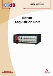
DBTRIG32 ACQUISITION SOFTWARE : USER MANUAL - STANDARD & EXPERT MODES1.3. Environmental noise applicationsTo perform acoustical in the environment with a 01dB PC - based measurement chain, this is the listof the hardware elements required. This list is non-exhaustive and may vary from application toapplication.Transducer unit (dual channel measurements in option)• Type I or Type 2 condenser microphone (pre-polarised, externally polarised)• Associated preamplifier. It should supply the polarisation voltage for the condenser microphone ifrequired.• Outdoor microphone unit, containing both a microphone and a preamplifier, can be used for longterm noise monitoring applications.Accessories• Windshield to protect the microphone (or an all weather windshield or an outdoors microphoneunit).• Extension cable for connection to the acquisition unit.• Tripod for the microphone unit.• Measurement case for outdoors measurements.• Type 1 or Type 2 acoustical calibrator to perform calibrated measurements.Measuring instrument• Notebook, industrial or desktop computer, that meets the minimum requirements specified by01dB, with a Windows operating system.• Acquisition unit connected to the Notebook (e.g. SYMPHONIE box).• dBTRIG32 application software for measurement, dBTRAIT32 application software for processingand various optional modules.The photograph illustrates a field environmental noisemeasurement with a 01dB measurement chain. All these elements can be purchased from 01dB.Contact your sales' representative for more information. A complete description of how these different elementsinterconnected is given in the getting started manualdelivered with your systemCHAPTER 1 - DESCRIPTION OF A 01DB PC-BASED MEASUREMENT CHAIN PAGE 11
DBTRIG32 ACQUISITION SOFTWARE : USER MANUAL - STANDARD & EXPERT MODES2. MEASURING WITH DBTRIG322.1. Principle of measurementThere is a sequence of steps that the user should follow. This will lead not only to successfulmeasurement but also to rapid familiarity with the software. Each stage is described in the manual.Before proceeding with the measurement procedure shown below, it is necessary to set up themeasurement chain.• Stage n° 1: Set up of the measurement chainConnection of the hardware elements, definitions of their characteristics in the databases' utilitydBCONFIG32, set up of the signal conditioning options of both the transducer and the hardwareperipheral. Refer to the getting started user manual delivered with your system for more details.• Stage n° 2: Selection of acquisition hardware, transducer and calibratorChoose Setup / Hardware configuration. Select the correct transducer, calibrator, remote control ifrequired and hardware platform for each measurement channel. This command is not available if the main measurement window is open.• Stage n° 3: Opening a new Measurement fileSelect Setup/New or Open an existing file. Measurement files contain all the measurement parameters.At this stage the measurement window appears. Once the ON/OFF switch is set to ON, the screenpresents real time visualisation of the time histories of the recorded quantities. The recording is in Playmode and data will not be saved to a datafile until the measurement start is activated according to theprogrammed conditions• Stage n° 4: Calibrating of the systemSelect Setup/Calibration and perform the measurement chain calibration.• Stage n° 5: Setting the system parametersChoose Setup/Parameters. These include acquisition, storage, audio recording, period definition,threshold and gain settings, automatic calibration, coding and system alarms.• Stage n° 6: Setting the dynamic range for the measurementChoose Setup/ Dynamic range and select the appropriate dynamic range so that no overloads orunderloads occur. Automatic adjustment of the dynamic range by the software is also possible by usingthe command Setup / Parameters / Advanced parameters and Automatic gain shift tab.• Stage n° 7: Setting the visualisation parameters.Via the Display menu or the icons on the toolbar. Options include Layout, Time history, DigitalIndicators, Spectrum. Customise the visual interface of the instrument.• Stage n° 8: Starting the measurement...Easy to use icons for start, stop and pause are found on the vertical command bar of the measurementwindow. Alternatively, pre-programme the timing with periods and time slots.• Stage n° 9: Coding noise events on-line.dBTRIG32 offers direct coding of time events during acquisition either from the tool bar or from the pulldown menu.Each stage is described in the manual. Data processing is performed in the software moduledBTRAIT32.CHAPTER 2 - MEASURING WITH DBTRIG32 PAGE 13
DBTRIG32 ACQUISITION SOFTWARE : USER MANUAL - STANDARD & EXPERT MODES2.2. New functions and optional modulesFurther to the 32-bit environment of 01dB application software, dBTRIG32 features many new functionsthat did not exist in previous versions of the software:• New data file format (CMG) common to all 01dB application software packagesAll the noise data acquired by dBTRIG32 are now saved to the computer hard disk into a single datafilecalled measurement session (*.CMG), which stand for measurement campaign in French. It replacesthe LEQ datafiles (for noise levels and spectra) and the WAV datafiles (for audio records) of the 16-bitversions of 01dB software.• Measurement in physical unitsIt is now possible to acquire and display the measured quantities in physical units rather than decibels(for example, sound pressure can be expressed in Pascal directly).• Edition of the reference values for calculation of levels in decibels (dB)The user may now define the reference values of any physical unit for calculation of its level in decibels.This function may be useful for specific industrial applications.• Real time measurement of the spectrum in octaves and third octaves of time weighted levels(Lin, Fast, Slow or user-defined time constant)The real-time acquisition of an octave or third octave spectrum is now possible for Leq, Fast, Slow oruser-defined time constant quantities. Furthermore, the time weighted quantities are no longer based onshort Leqs calculations but also real Slow and Fast sound pressure level calculations, as defined instandard IEC651.• Triggering capabilities for various eventsThe acquisition of auxiliary events in dBTRIG32 (audio records, spectra, noise source codes and alarms)according to a user-defined threshold has been improved : management of various triggers (in adatabase).• Dual channel acquisition module (option)It is now possible to perform noise measurements on two channels simultaneously with this optionalmodule. With a special cable, the user may obtain a single measurement of 115 dB dynamic (from 20dBto 135dB), using both acquisition channels.• Online analysis of audio records during acquisition (option)The simultaneous analysis of audio records during acquisition is no longer performed by an externalapplication software module (dBAUDIO) but by a calculation server. In addition to ‘classical’ octave andthird octave analysis, dBTRIG32 computes in real-time spectrum and multispectrum in 1/6th, 1/8th,1/12th, 1/24th and 1/48th octave bands.• Vibration module (option)With this optional module, computation of overall levels according to ISO2631 standard has beenimplemented. The third octave frequency range is extended down to 1Hz and the sampling frequencycan be set under 40 Hz, depending on hardware, allowing extended analysis of long vibration signals.CHAPTER 2 - MEASURING WITH DBTRIG32 PAGE 14
DBTRIG32 ACQUISITION SOFTWARE : USER MANUAL - STANDARD & EXPERT MODES• <strong>Expert</strong> module (option)The expert module allows the user to define any combination of trigger conditions for recording audio orspectrum events and generate alarm signals.Thresholds can be either relative or absolute providing very flexible event detection and data storage.• Psychoacoustic module (option)Overall levels used in the field of airport noise assessment (PNL, PNLT) are calculated by the softwareand can be displayed and stored with other global values.Similarly, the Loudness level according to ISO532B (Zwicker) is also computed in real-time.• Use with a digital tape recorder DAT (system JAZZ)Jazz features real-time analysis of DAT recordings by using AES/EBU digital interface. When using asound level meter connected to a DAT recorder (environmental monitoring for example), Jazz will readthe tape in digital format, without loss of quality. The signal does not have to be recorded A weighted onthe tape, therefore simultaneous global readings and 1/3 octave analysis are possible.dBTRIG32, used with the Jazz acquisition card, allows the operator to manage band indexes of digitalaudio tapes (DAT).• Use of a sound level meter as an acquisition front-end (ACL mode)The ACL mode allows using a 01dB sound level meter as acquisition platform in dBTRIG32. The soundlevel meter sends calibrated data to dBTRIG32 via serial interface.The user can carry out long-term measurements even on sound level meters without storage function. Acontinuous surveillance can be included without any interruption of the measurement. Optional modules are described in chapter 13.CHAPTER 2 - MEASURING WITH DBTRIG32 PAGE 15
DBTRIG32 ACQUISITION SOFTWARE : USER MANUAL - STANDARD & EXPERT MODES2.3. <strong>User</strong> level of the softwareIn the Preferences menu of dBTRIG32, the user may choose in between three different levels : Light,<strong>Standard</strong> and <strong>Expert</strong> modes. Each level gives access to different functions.The table below shows all the functions per software module:Light version <strong>Standard</strong> version <strong>Expert</strong> version- Quantities : Leq (A or Lin frequencyweightings), Peak (C or Lin frequencyweightings), time weightings- Quantities : Leq (A, B, C, G or Linfrequency weightings), Peak (C or Linfrequency weightings), timeweightings, 1 statistical indice Ln, 1user-defined time constant- Dual channel (option)- maximum dynamic (option)- All type of transducers- Spectra (Leq, Fast, Slow) in real-timein octaves and third octavesAcquisition- Single channel- Noise measurements only- Fixed Leq and audio pass bandfixed to 20kHzPsychoacoustics module:- Loudness, PNL, and PNLT.Vibration module:- Audio pass band upper limit rangingfrom 40 Hz to 20 kHz- ISO2631 and 8041 vibrationalweightings- Spectra :octaves 2Hz - 16kHz1/3 octaves 1Hz - 20 kHzIdentical to standard versionStorageCodingDisplay- <strong>Manual</strong>- 1 or more quantities- Audio recording manually oraccording to a simple absolutethreshold- <strong>Manual</strong> (6 codes from F4 to F9)- Delayed coding possible- Only one quantitytime history of fixed duration(1000pts) + associated digitalindicatorsUse with a DAT recorder(system Jazz only)- <strong>Manual</strong>, clock or user-defined periods- All acquired quantities + spectrum- Audio recording manually oraccording to a trigger- <strong>Manual</strong> (6 codes from F4 to F9)- Delayed coding possible- Definition of independent codes perchannel- Up to 6 acquired quantities- Averaged Leq display- Digital indicators associated to onedisplayed quantity- Display on the same plot the timehistories of active channels, only if theacquisition parameters of bothchannels are identical- Identical to standard version+ spectrum or multispectrumevent, acquired according to atrigger- Identical to standard version- Simultaneous coding- Coding according to a trigger- Identical to standard version Consult the dBTRIG32 light version manual for more details on this mode. When the user selects a new user level, the application software has to be restartedCHAPTER 2 - MEASURING WITH DBTRIG32 PAGE 16
DBTRIG32 ACQUISITION SOFTWARE : USER MANUAL - STANDARD & EXPERT MODES2.4. <strong>Mode</strong>s of operationsdBTRIG32 has three modes of operation:2.4.1. Inactive modeThe inactive mode closes the interaction between the acquisition platform and computer interface. It isaccessible either from the ON/OFF icon found at the top right corner of the measurement screen or fromthe Menu Setup / Hardware ON/OFF. The inactive mode reduces power consumption. Active mode willbe resumed automatically if a pre-programmed acquisition begins.2.4.2. Play modeWhile configuration parameters are set, dBTRIG32 displays the signal reading without recording (savingto hard disc). The real time visualisation of the results enables configuration parameters to be set beforethe measurement is recorded.• The configuration parameters may be saved to a file for use with subsequent measurements underthe same conditions.• Record mode may be initiated manually by the user or automatically at a pre-programmed time.2.4.3. Record modeData acquisition is recorded and saved to hard disk. Note that once recording, the acquisitionparameters are unavailable for modification.• During recording, the acoustical quantities identified for measurement are saved to hard disk. Ifaudio recording is active, dBTRIG32 records the whole of the signal to disk according to a trigger• During the measurement, the operator can activate the pause button as a simple method of editingunwanted signal input. Under record mode, the user has six coding options to identify noises. See the following chapters for further details on the command available for each of the functions ofdBTRIG32.CHAPTER 2 - MEASURING WITH DBTRIG32 PAGE 17
DBTRIG32 ACQUISITION SOFTWARE : USER MANUAL - STANDARD & EXPERT MODES3. MEASUREMENT HARDWARE CONFIGURATIONHardware specification and settings are required before any measurement. The Hardwareconfiguration option is found under the Setup menu of dBTRIG32 main window. This dialog box (seebelow) features various tabs : Hardware Peripheral is used to define which hardware elements areused to perform an acquisition (hardware peripheral, transducers, calibrators, active channels), Remotecontrol is used to define and configure a remote control object (this tab is displayed only if the fileDBCD32.INI is present in the 01dB program files directory). If you are using a 01dB Sound Level Meter as an acquisition front-end, see chapter 13.6.From the hardware peripheral tab, define:• The type of hardware platform• The active measurement channels• For each channel, a couple transducer / calibratorof same type• The signal conditioning options of the selectedhardware peripheral (Configuration key)The hardware configuration defined here will berecalled automatically next time the program is used.The acquisition platforms, transducers and calibratorsare selected from hardware elements' databasesdefined under the hardware configuration programmedBCONFIG32. Access to tachometric transducers is onlyavailable in dBFA32.• HardwareThe hardware board configuration sets up the computer so that it will be able to record data generatedby the specified board. It sets the number of possible active channels. The Configuration key givesaccess to signal conditioning options, built-in the hardware unit.• Active channelsAmong the possible channel(s) available on the acquisition unit, define which channels will be active forboth acquisition and calibration.• TransducerThe transducer configuration loads the transfer function of the selected transducer and allows theconversion of measured data into an input voltage and the reverse process after data analysis to displaythe results. A transducer must be prescribed to each active channel.• CalibratorThe calibrator configuration allows the user to perform the calibration routine, which adjusts the transferfunction of the transducer in order to perform calibrated and accurate measurements. A calibrator mustbe declared for each active channel. To enable direct power supply of a transducer from a SYMPHONIE unit or a JAZZ acquisitioncard, define the same option(s) for the transducer(s) and for the hardware platform(Configuration command). Selection, use and configuration of remote controls are dealt with in chapter 12. For more information concerning hardware configuration, refer to the getting started manualdelivered with your measurement system.CHAPTER 3 - MEASUREMENT HARDWARE CONFIGURATION PAGE 19
DBTRIG32 ACQUISITION SOFTWARE : USER MANUAL - STANDARD & EXPERT MODES4. MEASUREMENT CONFIGURATION FILESThe measurement configuration files of dBTRIG32 determine the parameters under whichmeasurements are triggered, recorded and saved. (Commands Setup / New, Setup / Save and Setup /Open).This facility for pre-programming a measurement configuration enables non-experienced operators tocarry out measurements. The configuration files contains the following elements:Configuration parameters that are saved• Acquisition parameters• Storage parameters• Audio recording parameters• Recording time settings• Threshold/Gains settings• Automatic calibration, where applicable• Coding parameters• Alarm management, where applicable• Source namesScreen visualisation parameters, defined from the Display menu• General layout parameters• Time history selection• Digital Indicator selection• Spectrum display where applicable.• Fine tuning of axis and cursor settingsThe coloursThe user may change element colours, to suit personal preferences. Note that the current dynamic range of the measurement is also saved.When an existing measurement configuration file is loaded, the acquisition software set-up theacquisition, storage and display parameters such as defined in the configuration file.The main acquisition window of dBTRIG32 is displayed once a new or existing measurementconfiguration is loaded. In standard mode, the measurement configuration files have the extension TRN, while in the expertmode, the measurement configuration files have the extension TRE.CHAPTER 4 - MEASUREMENT CONFIGURATION FILES PAGE 21
DBTRIG32 ACQUISITION SOFTWARE : USER MANUAL - STANDARD & EXPERT MODES5. MEASUREMENT CHAIN CALIBRATIONCalibration is recommended before every measurement. Calibration guarantees the reliability of theresults.Calibration affects the sensitivity of the selected transducer by adjusting it as a function of measured andexpected values (defined by the frequency and level characteristics of the calibrator). The calibrators andtransducers are defined by using dBCONFIG32 and they are selected using the Hardwareconfiguration command in the Setup menu.The current calibration is done using Leq over a 125-millisecond period. It measures the Leq value of theinput signal and converts it into the unit set in the transducer’s characteristics. By adjusting the level tothe expected level, it changes the sensitivity of the transducer. By validating it, the adjusted value willnow become the default value for the next time the program is used.Access Calibration via the Setup menu.The input gain and transducer sensitivity may becalibrated from the control panel Values may bemodified using the ‘+’, ‘-’ and ‘Adjust’ buttons.Calibration levels can be expressed either in dB orin physical units.On validation, the system is ready to carry outcalibrated measurements.Caution! Before calibration:• Verify that the calibration signal remains constant for a sufficiently long period.• Verify that the gain view meter is correctly positioned (neither too weak, nor overloading).• It is preferable to place the calibrator on foam to reduce the effect of vibrations.Caution! After calibration:• If, for the same transducer / calibrator pair, the sensitivity after calibration differs greatly from theoriginal sensitivity, damage to the microphone may have occurred.• If the measured values are not correct but the calibration value is OK, it could mean that thesensitivity of the microphone is correct only at 1 000 Hz. Check the microphone membrane.A microphone is very fragile equipment. A fall of 10-cm may damage the microphone membrane.As general rule, if the measured value in dB varies by +/- 1.5 dB from the value that would bemeasured with the microphone according to the original sensitivity (see calibration data sheet),consider your microphone as faulty.Example: For a microphone that as a factory sensitivity of 50 mV / Pa and a calibrator thatdelivers 94 dB at 1000 Hz.The microphone is able to perform correct measurements if:• The measured calibration level lies between 92.5 dB and 95.5 dB.• The current microphone 'sensitivity lies between (around) 40 mV/Pa and 60 mV/Pa ( multiplyor divide the original value by a factor of 1.1885)For greater or lower microphone 'sensitivities, consider the microphone as faulty. Return it toyour 01dB agent.CHAPTER 5 - MEASUREMENT CHAIN CALIBRATION PAGE 23
DBTRIG32 ACQUISITION SOFTWARE : USER MANUAL - STANDARD & EXPERT MODES6. DBTRIG32 MEASUREMENT WINDOWComplete control of the measuring instrument is available from the dBTRIG32 measurement window. Itis displayed when a measurement configuration file is opened. The main windows features the followingelements:• Command toolbar• Horizontal toolbar• Time history plot• Spectrum plot• Information bars• Status barThe measurement window is slightly different in standard and expert modes.In expert mode, it is possible to record spectrum as events. An event information for the spectrum and akey in the command bar are therefore added to access this functionality. The measurement window parameters can be saved in a configuration file by using the commandsSetup / Save or Save as. It is possible to display full screen the time history plot or the spectrum plot by double clicking on it.Double click again on the plot to go back to a full display.CHAPTER 6 - DBTRIG32 MEASUREMENT WINDOW PAGE 25
DBTRIG32 ACQUISITION SOFTWARE : USER MANUAL - STANDARD & EXPERT MODES6.1. Measurement window command barThis toolbar is used to configure and run the measurement.Show overloads andunderloads and reset digitalindicators (click on the centrebutton). The top section presentsthe overload indicators (on theleft, an instantaneous indication,on the right, hold if an overloadoccurred. The bottom sectionpresents underload indicationsStart / Stop dialogbetween theapplication softwareand the acquisitionperipheralDisplay an informationwindow about thecurrent measurementparameters.Generic filename (measurementsession *.CMG)Selection of a fixed dynamic range forthe measurement.It is however possible to automaticallyadjust the dynamic range while storingdata by using the commandConfiguration / Parameters - Advanced- option Automatic gain.Start / Stop an audio recordingmanually, whatever the triggerconditions defined to acquire audioevents.Measurement parameters(acquisition, storage, coding,automatic calibration and gainadjustment)Calibration(recommended before anymeasurement).Storage of the noise dataon the hard disk.Stop storage of the noisedata on the hard disk.Start / Stop recording aspectrum event manuallyPause : noise data is still storedon the hard disk but they areautomatically coded, so that theyare no taken into account for laterprocessing operations.Insert commentsmeasurementduring6.2. Measurement window horizontal toolbarThe toolbar defines the content of the visualisation, and enables dynamic coding of noise events:Set-up of the contents of the measurement window (curves' display mode, cursors' values, display informationbars, legend, type of scale used, etc.)Set-up the digital indicators in the measurement window. Shown quantity ( Leq, Peak, Slow, ... ),displayed values (Instantaneous, cumulated, Maximum, Minimum, cumulated duration), space sharebetween the indicators and the time history plot.Start source coding by clicking on the adequate coding button. The noisedata will be associated to this code number until another code is applied orif the user stops the current coding operation.Set-up of the spectrum plot : display dynamic, show max / min and averaged spectra.Set-up of the time history plot : select the quantities to display, duration of the display, displaydynamic range.CHAPTER 6 - DBTRIG32 MEASUREMENT WINDOW PAGE 26
DBTRIG32 ACQUISITION SOFTWARE : USER MANUAL - STANDARD & EXPERT MODES6.3. Measurement window status barThis status bar presents from left to right : the name of the measurement session where data is logged,the status of the measurement or the type of trigger used to start data logging, the duration andremaining duration of the measurement and the number of audio records that have not yet beenanalysed by the calculation server.To change the datafile name, use the command Measurement / New filename.To modify the measurement duration, use the command Setup / Parameters / Storage.6.4. Time history plotThe time history plot window displays the time history of the any acquired quantities (see paragraph 8.2).CursorIndicatorsAudio events'information barLegendSource codes'information barThe indicators at the top of the display window indicate the instantaneous values of the displayed noisequantities at the cursor location (at the contrary of the digital indicators of the measurement window thatpresent overall noise levels).Double click on these indicators to select which quantities will be displayed.The audio information bar indicates when audio records are acquired. It gives the time limits of anysingle audio event. When audio analysis is activated, the colour of the audio event reference changeswhen this particular event is being processed.The code information bar indicates the time limits of the active code. Six different sources may bedefined by the user.In expert mode only, an additional information bar is shown for spectrum events.CHAPTER 6 - DBTRIG32 MEASUREMENT WINDOW PAGE 27
DBTRIG32 ACQUISITION SOFTWARE : USER MANUAL - STANDARD & EXPERT MODES6.5. Spectrum plotIndicatorsCursorThe real-time octave or third octave spectrum acquired (see paragraph 7.1.2) is shown in this displaywindow. The plot is refreshed for each integration time.The minimum, maximum and averaged spectra can also be shown along with the instantaneousspectrum. When the reset indicator command is used, the display is cancelled as for the digital indicators(see paragraph 8.4).The indicators at the top of the display window indicate the instantaneous values of the displayedSpectra at the cursor location.Double click on these indicators to select which quantities will be displayed.6.6. Definition of auxiliary event (expert mode)dBTRIG32 in expert mode allows the user to record different type of events simultaneously to the maindata flow (overall noise quantities, spectra). The following auxiliary data can be acquired:• Audio records• Averaged spectra over the event duration• Mutlispectra• Codes• AlarmsAudio events and spectrum events may be triggered either manually from the measurement windowcommand bar or by using a trigger, that consists of threshold and time conditions.Coding of a single or several noise sources may be triggered either manually from the measurementwindow command bar or by using a trigger that consists of various threshold conditionsSignal alarms may be activated only for a trigger made of threshold conditions. To trigger an alarm, aremote control object has to be defined at the hardware configuration stage.For each type of event (audio, spectra, codes, alarms), the user may define overall parameters(maximum event duration, event stretching before and after the acquisition, etc.) specific to each eventas well as various triggers.Triggers defined in dBTRIG32 may be used for all types of auxiliary events. The way triggers are definedand used is dealt with in the following chapter.CHAPTER 6 - DBTRIG32 MEASUREMENT WINDOW PAGE 28
DBTRIG32 ACQUISITION SOFTWARE : USER MANUAL - STANDARD & EXPERT MODES7. MEASUREMENT PARAMETERS (SET-UP)The commandSetup / Parameters regroups most of theparameters that have to be defined before starting a measurement. Thiscommand allows the user to define:• Acquisition parameters• Storage parameters• Source coding parameters• Advanced parameters (automatic gain shift, automatic calibration,alarm event in expert mode)By clicking on OK, all the parameters that have been defined are applied tothe measurement system. Some parameters are different in standard and expert modes. Both settings are describedand clearly identified in this manual.7.1. Acquisition parametersUse this command (Acquisition key) to define the measurement acquisition parameters. The dialogshown below features three different tabs in order to define :• Overall acquisition parameters (Overall tab), such as the measurement passband.• Acquired quantities per measurement channel (Channel tab), such as a third-octave spectrum.• Any additional quantities to measure (Advanced tab), such as a Ln statistical indice.7.1.1. Overall tab• Maximum frequency : Fixed to 20 kHz.It corresponds to the maximum analysis frequency for acquisition oftime quantities. It defines the frequency pass band taken intoaccount for the calculation of Leq, spectrum and other indicators.• Maximum audio frequencySome hardware peripherals authorise a different frequency passband for audio recording than for time level quantities. Anysubsequent frequency analysis of an audio record will beperformed up to this frequency only.• Time baseIt corresponds to the acquisition rate. This period also correspondsto the logging and display rate. One value per time base will becalculated. The values of this parameter depend upon the selectedhardware platform.• Input –Output Loop. By activating this option, the user canlisten to the input signal (from the microphone) with earphonesplugged to the output channel.• Management of indexes on DAT bands. By activating this option, the user can manage DAT tapeindexes with a JAZZ system. Refer to the JAZZ information manual for more details.• Maximum dynamic. With a special cable, the user can link two measurement channels in order tomake a single one of greatest dynamic (typically 115dB with SYMPHONIE). A single measurementrange from 20dB to 135dB is thus available. Refer to paragraphs 11.4 and 13.2 for more details.CHAPTER 7 - MEASUREMENT PARAMETERS (SET-UP) PAGE 29
DBTRIG32 ACQUISITION SOFTWARE : USER MANUAL - STANDARD & EXPERT MODES7.1.2. Channel(s) tabThis tab is used to define the following parameters,either for all active measurement channels or foreach channel individually.Weightings• Frequency weightings to apply to all acquiredquantities except the Peak level that has anindependent network. A, B, C, G and Linfrequency weightings are available.• For peak values, C and Lin weightings areavailable. If the Vibration module is available, theISO2631 vibrational weightings can be selectedin this field. See paragraph 13.3.Additional measured quantities• Calculation of sound pressure levels accordingto the following time weightings : Fast, Slowand Impulse.If this option is selected, the following quantities willbe calculated : Slow Inst, Slow, Slow Min, SlowMax, Fast Inst, Fast, Fast Min, Fast Max,Impulse, Impulse Max. For more details on the calculation of time weighted sound pressure levels, refer to paragraph 16.1• Psychoacoustics calculations (option) : PNL, PNLT, and Loudness. Click on the configurationkey to define additional calculation parameters for Loudness and PNLT calculations. For more details on the calculation of these psychoacoustics criteria, refer to paragraph 13.4.• Spectrum : this option is used to calculate (or not) the real-time spectrum in order to obtain the timehistory of sound pressure levels per octave or third octave frequency bands (digital filteringtechnique).Select to the left the type of quantity to measure per frequency band (Leq, Slow, Fast, Other) and to theright the analysis resolution (octave or third octave) and the frequency limits (from 31.5Hz to 20kHz inoctave bands and from 20Hz to 20kHz in third octave bands).Tick the "Inst" box to calculate instantaneous time weighted sound pressure level. The spectral values are only guaranteed if they are greater or equal to the lower limit of theactive dynamic range - 5dB For more details on the calculation of time weighted sound pressure levels, refer to paragraph 16.1Choose as well if the data will be logged in physical units or in decibels.CHAPTER 7 - MEASUREMENT PARAMETERS (SET-UP) PAGE 30
DBTRIG32 ACQUISITION SOFTWARE : USER MANUAL - STANDARD & EXPERT MODES7.1.3. Advanced tabThis tab is used to define the following parameters, eitherfor all active measurement channels or for each channelindividually.• Statistical indice LnA statistical indice Ln can be measured in real-time.Define which acquired quantity will be used for thecalculation of the fractile indice Ln to calculate and thefloating period of the calculation.The indice L corresponds to the percentage of time duringwhich the selected quantity is exceeded.The software calculates a floating indice : it will becalculated for each time base taking into account theperiod of the calculation.In the example shown aside, the statistical indice that willbe calculated corresponds to the Leq level that isexceeded during 90% of the time over the last minute ofmeasurement. In practice, use L90,0 or L95,0 to approximate the background noise level of a noise climate andL10,0 to approximate the loudest noise source over the measurement duration.• <strong>User</strong>-defined time constantSelect if you wish (or not) to calculate time weighting to apply to sound pressure level calculations. Enterits value. This quantity is identified as a RC in the software.Once the acquisition parameters are defined, define the storage parameters. In other words,define the quantities that will be logged on the computer hard disk.CHAPTER 7 - MEASUREMENT PARAMETERS (SET-UP) PAGE 31
DBTRIG32 ACQUISITION SOFTWARE : USER MANUAL - STANDARD & EXPERT MODES7.2. Storage parameters (standard mode)Use this command (Storage key) in order to define the data logging parameters. This dialog bow (shownbelow) features three different tabs to define :• The way the measurement will be started and its duration (Overall tab)• The acquired quantities to store per measurement channel (Channels tab)• The way audio events will be triggered (Audio event tab) WARNING The data logging parameters in standard mode and in expert mode are not exactly the same.Each mode is described in this manual.Refer to paragraph 7.3 for the definition of storage parameters in expert mode.7.2.1. Overall tabThis tab is used to define the way the measurement will bestarted. A measurement in dBTRIG32 may be triggered inthree different ways:• <strong>Manual</strong><strong>Manual</strong>ly start the acquisition for a given duration (formatday / hour / minutes / seconds).• ClockThe time and date is programmed to start measuring• PeriodicChoose from one of the existing periods. Recording isactivated during time slots specified by the user, each timethe period repeats itself. (for example, daily from 8 a.m. to8 p.m.)Define the measurement location as well to later identifythis measurement session.The data logging periods allows the user to define periods without overlapping, over a day cycle or aweek cycle.The choice 24 hours means that it will be repeated identically whatever the day of the week. (Forexample, no difference will be made between results in the time slice 8h-20h of a week day and a bankholiday day).The choice 7-day, means that the software can differentiate between weekdays' periods (for example 8h– 20h) and weekend periods (for example from Friday 18h to Monday 6h). The periods' definition for data logging is also done in this dialog box. Refer to paragraph 7.7 formore information.CHAPTER 7 - MEASUREMENT PARAMETERS (SET-UP) PAGE 32
DBTRIG32 ACQUISITION SOFTWARE : USER MANUAL - STANDARD & EXPERT MODES7.2.2. Channels tabThis tab is used to define the following parameters, eitherfor all active measurement channels or for each channelindividually.Data logging of overall quantitiesdBTRIG32 allows the user to store the time history of allthe acquired quantities. The following overall quantitiescan be stored in a measurement session file:• LEQ, Peak• Time weightings (Fast, Fast Min, Fast Max, FastInst, Slow, Slow Min, Slow Max, Slow Inst, Impulse,Impulse Max)• <strong>User</strong> defined time constant (RC, RC Min, RC Max,RC Inst)• Psychoacoustic criteria (PNL, PNLT, Loudness)• <strong>User</strong>-defined statistical indiceSelect overall quantities in the Acquired quantities list and click on to add them to the Storedquantities list.At the contrary, select overall quantities in the Stored quantities list and click on to remove themfrom the list. There are passed into the Acquired quantities list. One cannot log quantities that are not defined in the acquisition parameters (see section 7.1).If, for example, the Spectrum function is not activated in the Channels tab of the acquisitionparameters, noise levels per frequency band cannot be acquired and saved in a measurementsession file.Tick respectively the box Spectrum storage and Audio record storage to save the spectrum and audioevents into a measurement session file.The field Transducer location can be useful for dual-channel measurements with different data loggingparameters for each channel (box All not activated).CHAPTER 7 - MEASUREMENT PARAMETERS (SET-UP) PAGE 33
DBTRIG32 ACQUISITION SOFTWARE : USER MANUAL - STANDARD & EXPERT MODES7.2.3. Audio event tabSimultaneously to the acquisition of overall quantities,dBTRIG32 may acquire and save audio signals, accordingto several parameters.In this tab, define first general parameters for theacquisition of audio events.Define the maximum event duration at the format days /hours / minutes / seconds.Define a pre-trigger option allowing audios recording tostart X milliseconds before or after the trigger condition isfulfilled.Then select the trigger that will be used to trigger theevent in the list of triggers.If the box use a trigger condition is not ticked, and if atleast one trigger has been defined, the events can only berecorded manually. Click on the iconevent.in the measurement window command bar to manually record an audioIf the box use a trigger condition is ticked, and if at least one trigger has been defined, an event will berecorded when the trigger conditions are fulfilled.For audio events, a trigger can be composed of two types of conditions :• Periodic : Audio records are made periodically according to a period defined by the user.• Threshold : Audio records are made when a user-defined threshold condition (absolute, relative to anacquired quantity or relative between measurement channels) is fulfilled.As the acquisition of auxiliary events is independent of the measurement of noise quantities, the triggerconditions may be defined at any time, even during a measurement session in progress. The definition and configuration of event triggers are dealt with in paragraph 7.8 for dBTRIG32standard mode.CHAPTER 7 - MEASUREMENT PARAMETERS (SET-UP) PAGE 34
DBTRIG32 ACQUISITION SOFTWARE : USER MANUAL - STANDARD & EXPERT MODES7.3. Storage parameters (expert mode)Use this command (Storage key) in order to define the data logging parameters. This dialog bow (shownbelow) features three different tabs to define :• The way the measurement will be started and its duration (Overall tab)• The acquired quantities to store per measurement channel (Channels tab)• The way audio events will be triggered (Audio event tab)• The way spectrum events will be triggered (Spectrum event tab) WARNING The data logging parameters in standard mode and in expert mode are not exactly the same.Each mode is described in this manual.Refer to paragraph 7.2 for the definition of storage parameters in standard mode.7.3.1. Overall tabThis tab is used to define the way the measurement willbe started. A measurement in dBTRIG32 may betriggered in three different ways:• <strong>Manual</strong><strong>Manual</strong>ly start the acquisition for a given duration(format day / hour / minutes / seconds).• ClockThe time and date is programmed to start measuring• PeriodicChoose from one of the existing periods. Recording isactivated during time slots specified by the user, eachtime the period repeats itself. (for example, daily from 8a.m. to 8 p.m.)Define the measurement location as well to later identifythis measurement session.The data logging periods allows the user to define periods without overlapping, over a day cycle or aweek cycle.The choice 24 hours means that it will be repeated identically whatever the day of the week. (Forexample, no difference will be made between results in the time slice 8h-20h of a week day and a bankholiday day).The choice 7-day, means that the software can differentiate between weekdays' periods (for example 8h– 20h) and weekend periods (for example from Friday 18h to Monday 6h). The periods' definition for data logging is also done in this dialog box. Refer to paragraph 7.7 formore information.CHAPTER 7 - MEASUREMENT PARAMETERS (SET-UP) PAGE 35
DBTRIG32 ACQUISITION SOFTWARE : USER MANUAL - STANDARD & EXPERT MODES7.3.2. Channels tabThis tab is used to define the following parameters,either for all active measurement channels or for eachchannel individually.Data logging of overall quantitiesdBTRIG32 allows the user to store the time history of allthe acquired quantities. The following overall quantitiescan be stored in a measurement session file:• LEQ, Peak• Time weightings (Fast, Fast Min, Fast Max, FastInst, Slow, Slow Min, Slow Max, Slow Inst, Impulse,Impulse Max)• <strong>User</strong> defined time constant (RC, RC Min, RCMax, RC Inst)• Psychoacoustic criteria (PNL, PNLT, Loudness)• <strong>User</strong>-defined statistical indiceSelect overall quantities in the Acquired quantities list and click on to add them to the Storedquantities list.At the contrary, select overall quantities in the Stored quantities list and click on to remove themfrom the list. There are passed into the Acquired quantities list. One cannot log quantities that are not defined in the acquisition parameters (see section 7.1).If, for example, the Spectrum function is not activated in the Channels tab of the acquisitionparameters, noise levels per frequency band cannot be acquired and saved in a measurementsession file.Tick the box Audio record storage to save into a measurement session file the audio events.Tick the box Spectrum storage to save the real-time spectrum, as defined in the acquisitionparameters. In the expert mode, the spectrum may be stored by three different means:• Continuously : a spectrum is stored for each time base. We obtain the spectral time historyof a noise level per frequency band over the complete measurement duration.• By event : a spectrum is stored manually by the key of the measurement windowcommand bar or when the state of a defined trigger is "true". We obtain the spectral timehistory of a noise level per frequency band over the event duration.• Averaged by event : a spectrum is stored manually by the key of the measurementwindow command bar or when the state of a defined trigger is "true". We obtain a spectrumaveraged over the event duration.The field Transducer location can be useful for dual-channel measurements with different data loggingparameters for each channel (box All not activated).CHAPTER 7 - MEASUREMENT PARAMETERS (SET-UP) PAGE 36
DBTRIG32 ACQUISITION SOFTWARE : USER MANUAL - STANDARD & EXPERT MODES7.3.3. Audio event tabSimultaneously to the acquisition of overall quantities,dBTRIG32 may acquire and save audio signals,according to several parameters.In this tab, define first general parameters for theacquisition of audio events.Define the maximum event duration at the format days/ hours / minutes / seconds.Define a pre-trigger option allowing audios recording tostart X milliseconds before or after the trigger conditionis fulfilled.Then select the trigger that will be used to trigger theevent in the list of triggers.If the box use a trigger condition is not ticked, and if atleast one trigger has been defined, the events can onlybe recorded manually. Click on the iconevent.in the measurement window command bar to manually record an audioIf the box use a trigger condition is ticked, and if at least one trigger has been defined, an event will berecorded when the trigger conditions are fulfilled.For audio events, a trigger can be composed of two types of conditions :• Periodic : Audio records are made periodically according to a period defined by the user.• Threshold : Audio records are made when a user-defined threshold condition (absolute, relative to anacquired quantity or relative between measurement channels) is fulfilled.As the acquisition of auxiliary events is independent of the measurement of noise quantities, the triggerconditions may be defined at any time, even during a measurement session in progress. The definition and configuration of event triggers are dealt with in paragraph 7.9 for dBTRIG32expert mode.CHAPTER 7 - MEASUREMENT PARAMETERS (SET-UP) PAGE 37
DBTRIG32 ACQUISITION SOFTWARE : USER MANUAL - STANDARD & EXPERT MODES7.3.4. Spectrum event tabSimultaneously to the acquisition of overall quantities,dBTRIG32 may acquire and save spectrum events,according to several parameters (see paragraph 7.3.2).In this tab, define first general parameters for theacquisition of spectrum events.Define the maximum event duration at the format days/ hours / minutes / seconds.Define an event stretching in number of spectra beforeand after the true event, knowing that dBTRIG32acquire a spectrum for each time base (see theacquisition parameters, overall tab, to change this timebase).We therefore can calculate the stretching duration Dcorresponding to the number of spectra selected N for atime base t by a simple multiplication : D = N * tIn the example shown aside, and for a time base of 200ms, a spectrum event will start 1 second before(5 * 200ms) and stop 1 second after (5 * 200ms) the duration for which the trigger state is true.Then select the trigger that will be used to trigger the event in the list of triggers.If the box use a trigger condition is not ticked, and if at least one trigger has been defined, the eventscan only be recorded manually. Click on the iconevent.in the measurement window command bar to manually record a spectrumIf the box use a trigger condition is ticked, and if at least one trigger has been defined, an event will berecorded when the trigger conditions are fulfilled (trigger state = TRUE).For spectrum events, a trigger can be composed of two types of conditions :• Periodic : Spectrum records are made periodically according to a period defined by the user.• Threshold : Spectrum records are made when a user-defined threshold condition (absolute, relativeto an acquired quantity or relative between measurement channels) is fulfilled.As the acquisition of auxiliary events is independent of the measurement of noise quantities, the triggerconditions may be defined at any time, even during a measurement session in progress The definition and configuration of event triggers are dealt with in paragraph 7.9 for dBTRIG32expert mode.CHAPTER 7 - MEASUREMENT PARAMETERS (SET-UP) PAGE 38
DBTRIG32 ACQUISITION SOFTWARE : USER MANUAL - STANDARD & EXPERT MODES7.4. Source coding parameters (standard mode)Use this command (Source coding key) to define noise source coding parameters.. dBTRIG32 allowsthe user to perform dynamic coding of noise events during the course of a measurement. The codingoption during parameter definition allows direct or delayed coding to be specified.7.4.1. Definition tabCoding noise events can be performed in two ways:• Direct (Allow delayed coding box not activated):coding of a noise source can be activated from thehorizontal toolbar of the measurement window byusing the coding buttons.• Delayed (Allow delayed coding box activated) :coding of the noise event begins X seconds (whereX is the coding delay parameter). This delay canbe visualised on the time history with a cursor.When performing dual-channel measurements, it ispossible to affect code numbers to a givenmeasurement channel only.In the group codes' management, select in the Code list a given code number and then affect it to agiven measurement channel in the Coded channels list. Repeat this operation for all the code numbersof interest.In the above example, the source 'Code 4' is affected to Channel 2 only. When using this code number,only noise data from the second measurement channel will be coded.If the user wishes to affect all codes numbers to all the active measurement channels, tick the box All bythe code list and the box All by the coded channel list.CHAPTER 7 - MEASUREMENT PARAMETERS (SET-UP) PAGE 39
DBTRIG32 ACQUISITION SOFTWARE : USER MANUAL - STANDARD & EXPERT MODES7.5. Source coding parameters (expert mode)Use this command (Source coding key) to define noise source coding parameters. dBTRIG32 allows theuser to perform dynamic coding of noise events during the course of a measurement. Coding can beperformed either manually (using the coding keys of the measurement window) or when a user-definedthreshold is exceeded The coding option during parameter definition allows direct or delayed coding tobe specified. A special feature allows coding noise data with several codes simultaneously.7.5.1. Definition tabActivate the option Allow multiple codes forsimultaneously code noise data with several noisesource codes.If this option is not activated, the current codingoperation will be stopped when another code isselected by the user. In other words, only one codingoperation at a time is allowed.Coding noise events manually can be performed intwo ways:• Direct (Allow delayed coding box not activated):coding of a noise source can be activated from thehorizontal toolbar of the measurement window byusing the coding buttons.• Delayed (Allow delayed coding box activated) :coding of the noise event begins X seconds(where X is the coding delay parameter). Thisdelay can be visualised on the time history with acursor.When performing dual-channel measurements, it is possible to affect code numbers to a givenmeasurement channel only.In the group codes' management, select in the Code list a given code number and then affect it to agiven measurement channel in the Coded channels list. Repeat this operation for all the code numbersof interest.In the above example, the source 'Code 4' is affected to Channel 2 only. When using this code number,only noise data from the second measurement channel will be coded.If the user wishes to affect all codes numbers to all the active measurement channels, tick the box All bythe code list and the box All by the coded channel list.CHAPTER 7 - MEASUREMENT PARAMETERS (SET-UP) PAGE 40
DBTRIG32 ACQUISITION SOFTWARE : USER MANUAL - STANDARD & EXPERT MODES7.5.2. Code event tabIts is possible to trigger noise event coding when auser-defined threshold is exceeded. For eachavailable code number (up to 6), define a thresholdtrigger.For a given code (Code 4 in the example), the usermay use a trigger (threshold) selected in the list oftriggers. Coding noise data with this code numberwill be performed automatically when the triggerstate is "TRUE".Define an event stretching in number of elementaryunits before and after the true event, knowing that anelementary unit corresponds to the time base ofacquisition in dBTRIG32 (see the acquisitionparameters, overall tab, to change this time base).We therefore can calculate the stretching duration Dcorresponding to the number of elementary unitsselected N for a time base t by a simplemultiplication : D = N * t.In the above example, and for a time base of 200ms, a code event (code 4) will start 0.8 second before(4 * 200ms) and stop 0 second after (0 * 200ms) the duration for which the trigger state is true For each available code, the user may define different parameters (event stretching, trigger used). Beware that when using a threshold condition to trigger a noise event, delayed coding shouldnot be activated (in the definition tab) otherwise, the software will start coding at the delayedcoding cursor position. The coded noise data will not correspond to the event because ofthat delay.If the box use a trigger is ticked, and if at least one trigger has been defined, an event will be recordedwhen the trigger conditions are fulfilled (trigger state = TRUE).As the acquisition of auxiliary events is independent of the measurement of noise quantities, the triggerconditions may be defined at any time, even during a measurement session in progress The definition and configuration of event triggers are dealt with in paragraph 7.9 for dBTRIG32expert mode.CHAPTER 7 - MEASUREMENT PARAMETERS (SET-UP) PAGE 41
DBTRIG32 ACQUISITION SOFTWARE : USER MANUAL - STANDARD & EXPERT MODES7.6. Advanced parametersUse this command (Advanced parameters key) to define the following parameters:• Activate an automatic gain shift for unattended measurements (Automatic gain shift tab)• Activate automatic calibration and / or calibration check for adapted microphone (Automaticcalibration tab).• Define alarm events in expert mode only (Alarm event tab)7.6.1. Automatic gain shift tabdBTRIG32 offers an automatic control option for the dynamic range during the course of measurement.Two control settings are available, automatic or fixed by activating / deactivating the Enabled option inthe dialog bow shown below.For automatic control, an underload or overload detection algorithm adjusts the dynamic rangeautomatically.For a fixed dynamic range (enabled box not activated), the operator chooses a dynamic scale accordingto the noise level of the measurement. See paragraph 7.10.Shift up if level above :• Upper threshold during X' seconds.• Maximum level during Y' seconds.Shift down if level below :• lower threshold during X seconds• minimum level during Y seconds.The principle of automatic control, as a function of the defined parameters is illustrated above. Automaticcontrol enables modification to the dynamic range corresponding to the measured noise levels. Overloadcriteria are defined, based on minimum and maximum gain levels as well as relative threshold levels withrespect to the overload levels.Each time an overload or underload occurs, the data will not be recorded for a short durationcorresponding to the time necessary to initialise the amplifiers of the acquisition unit. This initialisationduration is equal to 500 ms when A weighting is selected and to 4 seconds when no weighting (Lin) isselected. The "measured" values during the initialisation period are not taken into account in the loggeddata and in the digital indicators of the measurement window.Furthermore, the digital indicators, the overload and underload indicators are reset for each dynamicrange shift. Automatic gain shift allows the user to measure over a wide range of sound levels (typically20 -140dB. It is strongly recommended to select careful the parameters, as poor settings mayresult in continuous adjustments and hence important data loss. Refer to chapter 11 for more information on unattended measurements and automatic functions ofdBTRIG32.CHAPTER 7 - MEASUREMENT PARAMETERS (SET-UP) PAGE 42
DBTRIG32 ACQUISITION SOFTWARE : USER MANUAL - STANDARD & EXPERT MODES7.6.2. Automatic calibration tabdBTRIG32 manages automatic calibration andcalibration check during measurements when anadequate microphone unit is connected to themeasurement system.The dialog box shown aside allows the user to define ifautomatic calibration is active at the start and/or at theend of the measurement and sets the time period forwhich it is active (in seconds).Select as well if a calibration check duringmeasurement should be performed and its periodicity(every day, every hour, etc.)Access automatic calibration functions in dBTRIG32,when the appropriate remote control (to activate anelectrostatic actuator) is defined at the hardwareconfiguration stage. Refer to chapter 11 for more information onunattended measurements and automaticfunctions of dBTRIG32.7.6.3. Alarm event tab (expert mode)It is possible to define two alarm event that allows the userto generate a light signal when a user-defined threshold isexceeded (e.g.: flashing light system connected to the serialport of the PC enabled when a noise level is exceeded).Define an event stretching in number of elementary unitsafter the true event, knowing that an elementary unitcorresponds to the time base of acquisition in dBTRIG32(see the acquisition parameters, overall tab, to change thistime base).We therefore can calculate the stretching duration Dcorresponding to the number of elementary units selectedN for a time base t by a simple multiplication : D = N * t.In the above example, and for a time base of 200ms, analarm event (for the alarm n°1) will stop 0 second after (0 *200ms) the duration for which the trigger state is true.For a given alarm (Alarm 1 in this example) the user mayuse a trigger (threshold) selected in the list of triggers.Enabling an alarm signal will be performed automaticallywhen the trigger state is "TRUE". The definition and configuration of event triggers are dealt with in paragraph 7.9 for dBTRIG32expert mode The use of a remote control object to generate an alarm event is dealt with in chapter 12.CHAPTER 7 - MEASUREMENT PARAMETERS (SET-UP) PAGE 43
DBTRIG32 ACQUISITION SOFTWARE : USER MANUAL - STANDARD & EXPERT MODES7.7. Definition of storage periodsWhen selecting the start mode of data logging in dBTRIG32 (Overall tab of the storage parameters'dialog box), it is possible to define storage periods without overlapping, over a day cycle or a week cycle.The choice 24 hours means that it will be repeatedidentically whatever the day of the week. (Forexample, no difference will be made betweenresults in the time slice 8h-20h of a week day anda bank holiday day).The choice 7-day, means that the software candifferentiate between weekdays' periods (forexample 8h – 20h) and weekend periods (forexample from Friday 18h to Monday 6h).Several slots may be specified during a period but only one period may be active during measurements.7.7.1. 24 hour cycleThis section describes the procedure to program a 24-hour cycle.Give a name to the period (for example, day). To accept the time slot, click on Add. Use the up/downarrows to specify the exact start and end time. Validate with “OK”. The preceding window is re-displayedwith the current settings.Other time slots may be added, while existing entries may be modified or deleted, using respectively thebuttons Modify and Remove.CHAPTER 7 - MEASUREMENT PARAMETERS (SET-UP) PAGE 44
DBTRIG32 ACQUISITION SOFTWARE : USER MANUAL - STANDARD & EXPERT MODES7.7.2. 7 day cycleIn order to define a 7-day cycle, proceed as follows:For example, a period named “working days” has a 7day cycle, with time slots set between 8 a.m. and 8p.m.; from Monday to Friday inclusive.Add the first time slot: Monday, between 8 hrs and 20 hrs. Access the list of days and increment the timeusing the arrows adjacent to the boxes.Validate then repeat this operation for the other days until Friday. The Period Edition window contains 5-hour slots corresponding to the 5 days of the week.The list of periods is also adjusted The periods aresaved by default and are resumed at the next use ofthe program.Choose the storage period in the list (Overall tab,storage parameters dialog box). Data logging indBTRIG32 will start and end according to the definedperiod.In our example, data logging will occur every daybetween 08:00 and 20:00 hours.Note that an overlap of two time slots is not possible;and that from a calculation point of view, two timeslots that are concurrent will be considered as oneslot.CHAPTER 7 - MEASUREMENT PARAMETERS (SET-UP) PAGE 45
DBTRIG32 ACQUISITION SOFTWARE : USER MANUAL - STANDARD & EXPERT MODES7.8. Event triggers (standard mode)In dBTRIG32, it is now possible to define several trigger conditions (threshold or clock) to automaticallyacquire an auxiliary event (audio record for example).Several periods, for which the event acquisition according to a user-defined trigger is activated, can bemanaged by dBTRIG32. For example, define different threshold for day and night time to trigger anaudio record.As the acquisition of auxiliary events is independent of the measurement of noise quantities, the triggerconditions may be defined at any time, even during a measurement session in progress.By convention, we call a trigger the set of conditions defined by the operator. Several triggers may bedefined and used during a measurement session.In the example below, three different triggers have been defined : a clock trigger (acquisition of an eventevery 10 minutes), and two threshold triggers (acquisition of an event when the measured Leq levelexceeds 80dB and when the statistical indice L10 exceeds 70dB).Define a new triggerEdit an existing triggerDuplicate the triggerselected in the listDelete the triggerselected in the listAccess this dialog box by the tab Audio record of the storage parameters dialog box (see paragraph7.2.3).Select now the trigger that will be used to acquire automatically audio events. First, tick the box Use atrigger then select the appropriate trigger in the list.To define a trigger, proceed as follow:• Access the Audio event tab in the storage parameters dialog box• Click on the New key to define a new trigger• Give a name to this trigger• Define the time periods for which the trigger is active• Define the trigger conditions (clock and/or threshold) for each period of activity• Validate the configuration dialog box of the trigger• Repeat the above operations to define as many triggers as necessaryCHAPTER 7 - MEASUREMENT PARAMETERS (SET-UP) PAGE 46
DBTRIG32 ACQUISITION SOFTWARE : USER MANUAL - STANDARD & EXPERT MODESHere is an example of definition of a trigger. Thisdialog box is displayed when defining a new triggeror edit an existing trigger (with the Edit key).The upper part of the dialog shows the periods ofactivities of the trigger conditions.The threshold tab is used to define thresholdtrigger conditions.The clock tab is used to define clock triggerconditions.7.8.1. Periods of activity of a triggerIn the trigger configuration dialog box, edit periods (over a 24-hour cycle) for which the trigger conditionsare activated. Alternatively, the user may define different trigger conditions for different times of a day.Click on new period to define the start and end times (over a 24-hour cycle) of a period of activity.The trigger conditions defined for a Default period areactivated when no other periods are defined (in this case, thetrigger conditions are valid all the time) or for the time slots notcovered by other periods of activity. In order to define trigger conditions for each activity period, first select with the mouse a period in thelist. The active period is shown in inverse video.CHAPTER 7 - MEASUREMENT PARAMETERS (SET-UP) PAGE 47
DBTRIG32 ACQUISITION SOFTWARE : USER MANUAL - STANDARD & EXPERT MODES7.8.2. Threshold trigger conditionsOnce the periods of activity of the trigger have been defined, the user may define threshold and/or clocktrigger conditions.In the configuration dialog box, select the thresholdtab to define a threshold trigger condition.Tick first the box Enabled to activate a thresholdcondition.Tick the box Stop trigger action when level underthreshold to stop the event acquisition when thethreshold condition is not fulfilled anymore. Forexample, audio recording will be stop when themeasured level passes below a defined thresholdlevel)Define as well a minimum duration between twosuccessive records.To define a threshold itself, select the following parameters:• The type of threshold (absolute or relative to the acquired statistical indice)• The measured quantity considered defining a threshold level (Leq, Fast, Slow, frequency band,etc.).• For dual channel measurements, the measurement channel considered for calculating thethreshold level• The level in dB of the threshold trigger for an absolute threshold, or the difference in dBbetween the level of the selected measured quantity and the level of the acquired statisticalindice for a relative threshold Refer to paragraph 7.1 for more information on the acquired quantities and the acquired statisticalindice It is possible to combine threshold and clock trigger conditions.7.8.2.1. Example of absolute thresholdIn the example shown below, an event will be acquired when the Leq level measured on channel 2 isgreater or equal to 75dB.CHAPTER 7 - MEASUREMENT PARAMETERS (SET-UP) PAGE 48
DBTRIG32 ACQUISITION SOFTWARE : USER MANUAL - STANDARD & EXPERT MODES7.8.2.2. Example of relative thresholdIn the example shown aside, an event will be triggered whenthe noise level measured in the third octave band centred at1000 Hz on channel 1 is 20dB greater than the level of theacquired statistical indice.If, for example, the indice L95 is acquired (it is the noise levelexceeded during 95% of the time corresponding to thebackground noise), the threshold trigger will vary according tothe background noise level.For example, for a L95 level of 55dB, an event will be triggered each time the noise level in the 1000 Hzfrequency band exceed 75dB, that is 20dB above the background noise.This function can be useful for environmental noise measurements over day and night periods, when thebackground noise varies greatly.7.8.2.3. Example of absolute threshold : particular caseIf the user selects the statistical quantity in the list, the fieldsabsolute and relative are greyed.If for example, the L10 statistical indice is acquired (it is thenoise level exceeded during 10% of the time), an event will betriggered when the L10 level is greater or equal to 60dB.7.8.3. Clock trigger conditionOnce the periods of activity of the trigger have been defined, the user may define threshold and/or clocktrigger conditions.In the configuration dialog box, select the clock tab to define a clock trigger condition.To activate clock triggering of events, tick the box Use a clock trigger then define the duration of theevents and the periodicity of their acquisition (format: hour / minutes / seconds).In the above example, 10 second long events will be acquired every hour since measurement start. It is possible to combine threshold and clock trigger conditions.CHAPTER 7 - MEASUREMENT PARAMETERS (SET-UP) PAGE 49
DBTRIG32 ACQUISITION SOFTWARE : USER MANUAL - STANDARD & EXPERT MODES7.9. Event triggers (expert mode)In dBTRIG32, it is now possible to define several triggers conditions (threshold or clock) to automaticallyacquiring an auxiliary event (audio record, spectrum event, and code event or alarm event).Several periods, for which the event acquisition according to a user-defined trigger is activated, can bemanaged by dBTRIG32. For example, define different threshold for day and night time to trigger anaudio recordAs the acquisition of auxiliary events is independent of the measurement of noise quantities, the triggerconditions may be defined at any time, even during a measurement session in progress.By convention, we call a trigger the set of conditions defined by the operator. Several triggers may bedefined and used during a measurement session.In the example below, three different triggers have been defined : a clock trigger (acquisition of an eventevery 10 minutes), and two threshold triggers (acquisition of an event when the measured Leq levelexceeds 80dB and when the statistical indice L10 exceeds 70dB).Define a new triggerEdit an existing triggerDuplicate the triggerselected in the listDelete the triggerselected in the listAccess this dialog box by:• The tab Audio event (paragraph 7.3.3) and the tab Spectrum event (paragraph 7.3.4) of thestorage parameters dialog box• The tab Code event (paragraph 7.5.2) of the source coding parameters dialog box• The tab Alarm event (paragraph 7.6.3) of the advanced parameters dialog boxSelect now the trigger that will be used to acquire automatically audio events. First, tick the box Use atrigger then select the appropriate trigger in the list.Proceed as follow to define a trigger:• Access the event (audio, spectrum, code, alarm) tab from a dialog box of the measurementparameters• Click on the New key to define a new trigger• Give a name to this trigger• Define the time periods for which the trigger is active• Define the trigger conditions (clock and/or threshold) for each period of activity• Validate the configuration dialog box of the trigger• Repeat the above operations to define as many triggers as necessaryCHAPTER 7 - MEASUREMENT PARAMETERS (SET-UP) PAGE 50
DBTRIG32 ACQUISITION SOFTWARE : USER MANUAL - STANDARD & EXPERT MODESHere is an example of definition of a trigger. Thisdialog box is displayed when defining a new triggeror edit an existing trigger (with the Edit key).The upper part of the dialog shows the periods ofactivities of the trigger conditions.The threshold tab is used to define thresholdtrigger conditions.The clock tab is used to define clock triggerconditions.7.9.1. Periods of activity of a triggerIn the trigger configuration dialog box, edit periods (over a 24-hour cycle) for which the trigger conditionsare activated. Alternatively, the user may define different trigger conditions for different times of a day.Click on new period to define the start and end times (over a 24-hour cycle) of a period of activity.The trigger conditions defined for a Default period areactivated when no other periods are defined (in this case, thetrigger conditions are valid all the time) or for the time slots notcovered by other periods of activity. In order to define trigger conditions for each activity period, first select with the mouse a period in thelist. The active period is shown in inverse video.CHAPTER 7 - MEASUREMENT PARAMETERS (SET-UP) PAGE 51
DBTRIG32 ACQUISITION SOFTWARE : USER MANUAL - STANDARD & EXPERT MODES7.9.2. Threshold trigger conditionsOnce the periods of activity of the trigger have been defined, the user may define threshold and/or clocktrigger conditions.In the configuration dialog box, select the thresholdtab to define a threshold trigger condition.Tick first the box Enabled to activate one (or more)threshold conditions.Tick the box Stop trigger action when level underthreshold to stop the event acquisition when thethreshold condition is not fulfilled anymore. Forexample, audio recording will be stop when themeasured level passes below a defined threshold level).Define as well a minimum duration between twosuccessive records.To define threshold conditions, first click on the add button to define one condition, then repeat thisoperation for as many threshold conditions as required.The keys Modify and remove allow the user to respectively edit or delete the threshold condition selectedin the list (appears in inverse video).When several conditions are defined, a boolean operator (AND/OR) has to be defined. A thresholdtrigger will be activated when all the threshold conditions are fulfilled (AND operator) or when at leastone condition is fulfilled (OR operator).The condition definition dialog box appears on screen. Define the following parameters:• The type of threshold (absolute or relative)• The measured quantity considered defining athreshold level (Leq, Fast, Slow, frequency band, etc.).• The measurement channel considered for calculatingthe threshold level• The way of the threshold (quantity greater than orless than the threshold value)• For relative threshold, the second quantity (andassociated measurement channel) to compare to thefirst quantity.• The threshold level in dB for an absolute threshold,and the difference in dB between the levels of the firstand the second quantities selected. Refer to paragraph 7.1 for more information on theacquired quantities and the acquired statistical indice It is possible to combine threshold and clock trigger conditions.CHAPTER 7 - MEASUREMENT PARAMETERS (SET-UP) PAGE 52
DBTRIG32 ACQUISITION SOFTWARE : USER MANUAL - STANDARD & EXPERT MODES7.9.2.1. Example of absolute threshold conditionIn the example shown aside, the threshold, condition willbe fulfilled when the Leq level measured on channel 1 isgreater than or equal to 80dB.If only this condition as been defined, or if the OR operatoris selected, an event will be triggered when this thresholdcondition is fulfilled.7.9.2.2. Example of relative threshold conditionIn the example shown aside, the threshold condition will befulfilled when the Leq level measured on channel 1 is 20dBgreater than the noise level measured in the 1000Hzfrequency band on channel 2.If only this condition as been defined, or if the OR operator isselected, an event will be triggered when this thresholdcondition is fulfilled.7.9.2.3. Example of trigger with two threshold conditionsIf for a trigger, we define the two previous thresholdconditions and if we select the boolean operator OR, anevent will be triggered when the first condition is fulfilled(Leq channel 1 > 80dB) or when the second condition isfulfilled (Leq channel 1 > level 1kHz + 20dB) To trigger events according to a spectral pattern, the user has to define threshold conditions foreach frequency band of interest then to select the boolean operator AND. An event will be acquiredwhen all the threshold conditions are fulfilled.CHAPTER 7 - MEASUREMENT PARAMETERS (SET-UP) PAGE 53
DBTRIG32 ACQUISITION SOFTWARE : USER MANUAL - STANDARD & EXPERT MODES7.9.3. Clock trigger conditionOnce the periods of activity of the trigger have been defined, the user may define threshold and/or clocktrigger conditions.In the configuration dialog box, select the clock tab to define a clock trigger condition.To activate clock triggering of events, tick the box Use a clock trigger then define the duration of theevents and the periodicity of their acquisition (format: hour / minutes / seconds).In the above example, 10 second long events will be acquired every hour since measurement start. It is possible to combine threshold and clock trigger conditions.7.10. Dynamic range parametersdBTRIG32 allows manual selection of the dynamic range using the icon (or Setup menu /Dynamic range). This command allows the user to select the dynamic range of the measurement asfollow.The number of dynamic ranges available depends upon thehardware platform used. It usually varies between 5 or 6 ranges. Itis very important to carefully select the dynamic range as any levelmeasured outside this range will coded as an overload (code 2) oran underload (code 3) and the overload indicators in the commandbar of the measurement window will be lit in red.dBTRIG32 features dynamic ranges of 65dB maximum. It is thegreatest value for any one range of 16-bit acquisition hardware thatcomply with Type 1 specifications of the IEC804.The suggested dynamic ranges are absolute electrical ranges for agiven type of transducer. This means that they are electricallyidentical to the transducer being used (i.e. the highest range willalways cover the transducer being used).However, given that values are expressed in "acoustical" dB, thefinal values in the panel next to this will be different dependingupon the type and its sensitivity. In effect, the same electrical levelexpressed in "acoustical" dB for two transducers with differentsensitivities will give different levels (in dB).This initialisation duration when a dynamic range is selected is equal to 500 ms when A weighting isselected and to 4 seconds when no weighting (Lin) is selected. The "measured" values during theinitialisation period are not taken into account in the logged data and in the digital indicators of themeasurement window.Furthermore, the digital indicators, the overload and underload indicators are reset for each dynamicrange shift.CHAPTER 7 - MEASUREMENT PARAMETERS (SET-UP) PAGE 54
DBTRIG32 ACQUISITION SOFTWARE : USER MANUAL - STANDARD & EXPERT MODES7.11. Selective configuration tasksBefore setting up a measurement session, the user may perform the following operations in dBTRIG32:• Edition of the physical units and references for calculation of logarithmic levels in dB• Display line spectra rather than bar spectra• Define names for the noise source codes7.11.1. Conversion units and references management (from a physical unit to a dB level)Use the command Units' management under the Preferences menu. The following dialog box appearson-screen:dBTRIG32 allows the user to edit the default references and the units used for each type of transducer.Click on the modify key to edit the physical unit and/or the reference value of the selected quantity in thelist (appears in inverse video). Click on SI values key to select the values of the International system asstandard. This function cannot be accessed when a measurement is running. Close the measurementwindow to edit the references values and the units.Let us consider an example of conversion.For pressure type transducers, the reference value of the SI system is 2*10 e-5 Pa. The sound pressurelevel is given by the formula :Lp = 10 * log (p²/p0²) where p0 is the reference valueTherefore, for an acoustic pressure level of 2*10 e-2 Pa, dBTRIG32 will use a reference of p0=2*10 e-5 Pa,to calculate a sound pressure level of 60dB (that is 10*log[2(10 e-2 )²/2(10 e-5 )²]).If one define a reference level of p0=2*10 e-6 Pa, the sound pressure level displayed in dBTRIG32 will beequal to 80 dB.Likewise, it will be possible to edit these parameters for each type of transducer, depending on theapplication.CHAPTER 7 - MEASUREMENT PARAMETERS (SET-UP) PAGE 55
DBTRIG32 ACQUISITION SOFTWARE : USER MANUAL - STANDARD & EXPERT MODES7.11.2. Display line spectraUse the command Line spectra display under the Preferences menu.When this function is activated, the bar spectrum display is changed to a line spectrum display. This function cannot be accessed when a measurement is running. Close the measurementwindow to change the spectrum displayBar sepctrum displayLine spectrum display7.11.3. Definition of sources' namesUse the command Setup / Sources' names to modify the names and the colours associated with acode number.dBTRIG32 allows the user todynamically code noise data. Thiscommand is used to change the defaultnames of each code. The name of asource is automatically updated in thehorizontal toolbar of the measurementwindow.1. Select the source to edit in the list(appears in inverse video) and give aname to it in the right hand corner ofthe dialog box.2. The colour associated is displayed inthe right hand corner of the dialogbox.3. Select a different colour in the lower part of the dialog box to change the colour associated with thisnoise source.CHAPTER 7 - MEASUREMENT PARAMETERS (SET-UP) PAGE 56
DBTRIG32 ACQUISITION SOFTWARE : USER MANUAL - STANDARD & EXPERT MODES8. MEASUREMENT WINDOW DISPLAY PARAMETERSThe content and general format of the measurement window may be defined by the Display menucommands or from the horizontal toolbar. Options include display of cursor values and information bars,time history and spectra readings in landscape or portrait formats, selection of quantities to read,definition of the time period of the displayed time history (e.g. from 30s of data to over an hour), choice ofdigital indicators, etc.8.1. Command Display / LayoutThe following options are found under the Display / Layout menu, or the associated icon :• Layout for different viewsTick the box Display plots of different channels on sameview if you wish to show measured data from both channels onthe same plot. The measurement configuration must identicalon both channels (same type of transducers, same frequencyweightings, etc.)The displayed dynamic range will fit the minimum andmaximum levels of the two ranges previously used.As the spectrum plots will be displayed on the same graph, itmay be useful to display line spectra instead of bar spectra(See paragraph 7.11.2).Select the layout for the different views of two measurementchannels : vertical or horizontal.• Display contentsTick the box Time history plot cursors' values to displaymeasured levels at the cursor location on the time history plots.When several overall quantities are displayed on a time history plot, a cursor value bar is shown for eachone of them. Double click with the mouse on this field to select which indicators have to be shown.Tick the box Legend to display noise source names managed by dBTRIG32 as a legend on the timehistory plot.Tick the box Information bar to display the information bars relative to the acquisition of auxiliary events(audio, source and spectrum event bars).Tick the box Spectrum plot cursor value to display measured levels at the cursor location on thespectrum plot. . When several spectra are displayed on a spectrum plot, a cursor value bar is shown foreach one of them. Double click with the mouse on this field to select which indicators have to be shown.If you chose to display and acquire data in physical units (see paragraph 7.1.1), you may select the typeof scale (linear or logarithmic) to use for both time history and spectrum plots. If the measurement window is too small, most of these display indications are not shown, inorder to clearly read the graphics.• Layout of time history / Spectrum plotsDefine if the plots, for a given measurement channel, have to be shown side by side (horizontal) or ontop of one another (vertical). The spectrum plot space option is used to define how much space in thedisplay is reserved to the spectrum plot.CHAPTER 8 - MEASUREMENT WINDOW DISPLAY PARAMETERS PAGE 57
DBTRIG32 ACQUISITION SOFTWARE : USER MANUAL - STANDARD & EXPERT MODES8.2. Command Display / Time historyUse this optionto define the time history display characteristics:For dual-channel measurements,link the cursors on the timehistory plots (same position,same displacements)List of noise quantitiesthat can be displayedon the time historyplot. See below for thecomplete list.Quantities that will bedisplayed on the timehistory plot.Define the plot duration shown on the time history plot (format : hour / minutes / seconds).Furthermore, for each active measurement channel (or all of them), define:• The time history plots displayed to choose from a list of allowed quantities. Use the keys 1, 2, 3, 4,5 and 6 to choose, in a given order, the plots to display. The remove key is used to delete a quantityfrom the displayed plots list.• The display dynamic range: automatic (the display dynamic range on the time history plot isadjusted to the values of the measurement dynamic range), or manual (define the minimum andmaximum values to display on the plot)The list of allowed quantities that can be displayed correspond to the list of acquired quantities (seeparagraph 7.1.)CHAPTER 8 - MEASUREMENT WINDOW DISPLAY PARAMETERS PAGE 58
DBTRIG32 ACQUISITION SOFTWARE : USER MANUAL - STANDARD & EXPERT MODES8.3. Command Display / Digital indicatorsUse this commandmeasurement channels:to define the numerical indicator characteristics, for one or all the active• Displayed quantityThe quantity will be shown in the digital indicators. The list ofquantities to choose from correspond to all the quantitiesdisplayed on the time history plot (see paragraph 8.2).• ContentsThe type of indicators is: instantaneous, running average,maximum, minimum and the cumulated duration.These indicators are reset when the reset indicators commandis used.• Space share in graphical viewThis option is used to define how much space in the display is reserved to the indicators. In the aboveexample, the digital indicators will take a 1/6 th of the space reserved to the time history plot, and thegraphical view will take 5/6 th of that space.8.4. Command Display / SpectrumUse this command to define the spectrum display characteristics, for one or all the activemeasurement channels:Tick the box Linked cursors on views to link the cursors on thespectrum plots of each active measurement channels.The display dynamic range can be configured in two ways:automatic (the display dynamic range on the spectrum plot isadjusted to the values of the measurement dynamic range), ormanual (define the minimum and maximum values to display onthe plot)3 other spectra may be displayed: maximum / minimum /averaged spectra.These spectra are reset when the reset indicators command isusedCHAPTER 8 - MEASUREMENT WINDOW DISPLAY PARAMETERS PAGE 59
DBTRIG32 ACQUISITION SOFTWARE : USER MANUAL - STANDARD & EXPERT MODES8.5. Command Preferences / ColoursUse this command to set-up the colours of the different elements displayed in the measurement window.The colour of the element selected in the list (it appears in inverse video) is displayed in the right part ofthe dialog box. Select another colour (pick from the colours available in the lower part of the dialog box)and valid by OK. This colour scheme is global for the display and will be applied to all the plots. On validationof this dialog box, the new colour scheme to all the existing plots.8.6. Command Preferences / FontUse this command to select a different font for data display in the software.CHAPTER 8 - MEASUREMENT WINDOW DISPLAY PARAMETERS PAGE 60
DBTRIG32 ACQUISITION SOFTWARE : USER MANUAL - STANDARD & EXPERT MODES9. RECORDING A MEASUREMENTAfter measurement set-up and display configuration, data logging of the acquired quantities may begin.The data will be saved to the hard disk on the microcomputer in a measurement session file.9.1. Command Measurement / New filenameThis command is used to define a generic filename for the measurement session file. dBTRIG32allows the user to log data, using storage periods, by keeping the same file root name.A dialog box is displayed for the user to define the file name of the measurement session (*.CMG). Anybinary file (.BID) attached to the measurement session file is stored in the same directory on the harddisk. If no file name has been defined, the software will automatically prompt the user for this definition.9.2. Measurement : Start / Pause / StopThe start, stop and pause instructions can be activated either from the command bar to the right of themeasurement window or from the Measurement pull down menu. The icons are shown below:Start data logging (CTRL + B)Switch to Pause (free run) mode and inverselyStop data logging (CTRL + E) See paragraph 2.4 for more information on Pause and storage modes in dBTRIG329.3. Actions during a measurement session9.3.1. CommentsThe comment window ( or command Measurement/ Comment) may be displayed at any time duringmeasurement. Select the Start and End keys toassociate comments and the time they were made to aparticular section of the measurement.The comments are directly accessible from an information bar during the analysis stage of dBTRAIT32.9.3.2. Reset the indicatorsUse this command (Measurement / Reset indicators or ) to reset the digital indicators, theoverload and underloads flags and the elapsed time. The reset command can be applied at any time: itdoes not affect data logging.The quantities calculated in the digital indicators display is independent from data logging. Calculationsrestart each time a rest command has been used.CHAPTER 9 - RECORDING A MEASUREMENT PAGE 61
DBTRIG32 ACQUISITION SOFTWARE : USER MANUAL - STANDARD & EXPERT MODES9.3.3. Dynamic noise source coding while measuringThe use of dynamic coding to identify a noise source is a very powerful tool. The user is able to compileseveral noise source identifications during the acquisition phase or later during analysis of the results.During measurement, the coding algorithm determines the number of appearances for each identifiednoise source. This enables the contributions of each source with respect to its overall input to beappreciated.dBTRIG32 offers time event coding during the measurement. dBTRIG32 automatically identifies andcodes values that cause over or under-loading. In addition to this, the program allows 6 sources to becoded by the user. Dynamic coding may be operated from the horizontal toolbar of the measurementwindow or by using the F4 to F9 keys. To end stop dynamic coding, press the key or icon correspondingto the active source.The icons for 6 time event codes are illustrated above. Their colour and names may be changed to theuser’s preference Preferences / Colours and Set-up / Source names.The first stage in coding is to define which noise sources to consider. A source is defined by an identifier(a series of characters) and an internal identifier (numerical code). While a noise source is present, asection of the measurement is cut in order to act as an identification template.When the noise source is identified, the following results are calculated:: Particular Leq, Partial Leqpartial, SEL and LMAX and, by way of graphical display: Time history, Histogram Consult the dBTRAIT32 manual or the on line help file for more details on how to use the codingfacility9.3.4. <strong>Manual</strong> trigger of audio recording during measurementAn audio recording, independent of current threshold or clock trigger settings, may be initialised by thiscommand (Measurement / Audio record). As soon as data logging starts the following icon is availablefor use:Start / Stop audio recording manually (CTRL+A) If the button is greyed, it may mean that audio storage has not been activated. See paragraphs7.2.2 and 7.3.2.9.3.5. <strong>Manual</strong> trigger of spectrum event during measurement (expert mode)A spectrum event, independent of current threshold or clock trigger settings, may be initialised by thiscommand (Measurement / Spectrum record). As soon as data logging starts the following icon isavailable for use:Start / Stop spectrum event recording manually If the button is greyed, it may mean that audio storage has not been activated. See paragraph 7.3.2CHAPTER 9 - RECORDING A MEASUREMENT PAGE 62
DBTRIG32 ACQUISITION SOFTWARE : USER MANUAL - STANDARD & EXPERT MODES10. ONLINE ANALYSIS OF AUDIO RECORDS (OPTION)It is possible to user to analyse, in both frequency and time domains, audio records made with thesoftware dBTRIG32 either automatically at the time of acquisition in dBTRIG32 or at the processingstage in dBTRAIT32, using the multitasking capabilities of Windows:The analysis types are:• Frequency analysis (averaged spectrum over the audio event duration) in octaves, 1/3 rd octaves• Frequency analysis in 1/6th, 1/12th, 1/24th and 1/48th octaves (option)• Decimation or deletion of audio records to optimise audio storage capacity on the PC hard disk.• Multispectrum analysis of audio records (spectrum time history and A, Lin overall levels) (option)• Detailed time history (A, C and Lin in parallel, several time constants - Fast, Slow, Impulse, etc. –using very small time step,) (option)You can then evaluate tagged noise data using dBTRAIT32 - which permits detailed analysis of thenoise climate in both time and frequency domains.All these analyses are available through an operation (script) server, common to all 32-bit 01dBapplication software packages. The definition and configuration of such analyses can be accessedthrough the command Aux / Frequency analysis & advanced processing / Configure in dBTRAIT32and Audio Analysis / Configure analysis, key scripts' edition in dBTRIG32. The dialog box shownabove is displayed on-screen.The user then defines an analysis script that consists of a list of processings that will be applied to eachaudio event. For each type of processing (defined also as an operator), the user sets variousparameters.This utility saves time as you will not have to process the audio recordings manually any more.Furthermore, the multispectrum analysis is ideal for tonal components, which vary in frequency andlevel. If the option cannot be accessed, it means that the CMG datafile does not contain any audiorecordings.Once the analysis script is configured, it will execute automatically in the background each time anaudio event has been recorded.In the audio information bar of the measurement window, the colour of an audio event changes whenbeing processed (by default, an audio being analysed changes from a yellow colour to a red one).It is possible to stop manually the analysis process by using the command Interrupt analysis in themenu Audio analysis.CHAPTER 10 - ONLINE ANALYSIS OF AUDIO RECORDS (OPTION) PAGE 63
DBTRIG32 ACQUISITION SOFTWARE : USER MANUAL - STANDARD & EXPERT MODESThe following paragraphs deal with the configuration of each type of analysis, the activation of the scriptserver and the principle of analysis script.10.1. Activation of the analysis script serverActivate the calculation server by using the command Audio analysis / Configure analysis. Thefollowing dialog box is displayed on-screen:This dialog box allows the user to activate the calculation server an edit an analysis script for audioevents' analyses.The following parameters have to be defined :• Enabled : tick this box to activate the calculation server.• Channels : select the measurement channels on which recorded audio events will be analysed. Ifthe box All is ticked, it means that identical audio event analyses will be performed on all the activemeasurement channels. If this box is not ticked, the user may define an analysis script for eachactive measurement channels.• Scripts' edition : Click on this key to define an analysis script (select the type of analyses anddefine the calculation parameters).• Delete audio records at the end of calculation : tick this box if you do not want to keep audioevents after they have been analysis (No replay)Once a script is defined (and configured), click on OK.When dBTRIG32 records an audio event, the calculation server will automatically launch an analysisscript, and process audio records as soon as they have been acquired. By default, the last script used isrecalled when another measurement session is started.CHAPTER 10 - ONLINE ANALYSIS OF AUDIO RECORDS (OPTION) PAGE 64
DBTRIG32 ACQUISITION SOFTWARE : USER MANUAL - STANDARD & EXPERT MODES10.2. How to define and configure a scriptIn order to define the list of processings to apply to audio records, access this dialog box (command Aux/ Frequency analysis & advanced processing / Configure in dBTRAIT32 and Audio Analysis /Configure analysis, key scripts' edition in dBTRIG32):1 23 456 71. List of available processings: it shows all the types of processings compatible with the softwarepackages dBTRIG32 and dBTRAIT32. The same operator can be used several times with differentparameters to process the same audio recording.2. Designation: give a name to the script.3. Set of active processings currently part of the script. These operators will be activated to analyseindependently a set of audio events.4. Edit the parameters of the selected operator (in the list of available processings). Each operatorshows its own configuration dialog box.5. Comments describing the operator selected in the available processings' list. If an operator from theactive processings' list is selected, the comment field shows the type of the operator.6. Key >> that allows adding an operator into the active processings' list. Different operators of thesame type may be added (the user may for example define a multispectrum analysis in third octaveband with different time steps). A generic name for each operator is given by default.7. The key remove allows the user to remove an operator from the list of the active processings.Once the list of active processings has been defined, edit each one of them to define the calculationparameters.CHAPTER 10 - ONLINE ANALYSIS OF AUDIO RECORDS (OPTION) PAGE 65
DBTRIG32 ACQUISITION SOFTWARE : USER MANUAL - STANDARD & EXPERT MODES10.3. Configuration of each active processing.Once the list of active processings has been defined in the script configuration dialog box, define thecalculation parameters of each operator.To do so, select an operator in the list and click on the Edit key.An operator applies a given processing on a quantity or a set of quantities (audio data in the presentapplication software). Each type of operator has its own name and a set of analysis parameters.Furthermore, The progress of each calculation is shown to the user at user-defined intervals.In dBTRIG32 and dBTRAIT32, the following operators may be selected:• Broad band spectra (averaged spectra et multispectra)• Audio record undersampling• Detailed time history of an overall level10.3.1. Broad brand analysis (averaged spectra and multispectraIn the script configuration dialog box, select an operator of type - octave and third octave spectra - or,if you have the 1/N octaves option, - Broad band spectrum - in the list of available processings andplace it in the list of active processings. On operator of name FC is then created.Select this operator and click on the Edit key. The dialog box shown below is displayed on screen. Thetab Operator gives a detailed description of the operator and allows the user to define a more specificname for it.In the tab Configuration, the following analysisparameters may be defined:• Bandwidth to define the spectrum bandwidth for theanalysis: Octaves and 1/3 octaves by default, 1/1, 1/3,1/6, 1/12, 1/24 et 1/48 th octaves in option.• Min : Minimum centre frequency of analysis• Max : Maximum centre frequency of analysis• Full octaves: If this option is activated, the softwarewill set the minimum and maximum frequency limits sothat only full octaves are calculated.• Analysis: Select the method used to performfrequency analysis: FFT or digital filtering.• Multispectra: If this option is activated, the user will obtain the time history over the event durationof the calculated spectrum. The time step may vary from 1ms to 1 s.Furthermore, The choice of maximum frequency for the analysis will depend upon the samplingfrequency (approximately twice the measurement pass band) at which the measurements have beentaken from dBTRIG32: if a pass band of 10 kHz was defined for audio records, frequency bands greaterthan this cannot be obtained.CHAPTER 10 - ONLINE ANALYSIS OF AUDIO RECORDS (OPTION) PAGE 66
DBTRIG32 ACQUISITION SOFTWARE : USER MANUAL - STANDARD & EXPERT MODES10.3.2. Overall level analysis (detailed time history)A detailed time history analysis offers a zoom facility for the time history data over the duration of theevent.In the script configuration dialog box, select an operator of type - Overall level - in the list of availableprocessings and place it in the list of active processings. On operator of name LEQ is then created.Select this operator and click on the Edit key. The dialog box shown below is displayed on screen. Thetab Operator gives a detailed description of the operator and allows the user to define a more specificname for it.In the tab Configuration, the following analysisparameters may be defined:• Time step: it is the integration time for thecalculation of an overall Leq level. It may vary between 1ms and 1s.• Frequency weighting : select a frequencyweighting to calculate the overall level (A, B, C, Lin)• Time weighting : select the overall noise quantity tocalculate (Leq, Peak, Slow, Fast, Impulse)If, for example, a time step of 1 s is chosen for a 2 s longaudio recording, only two values will be calculated (onevalue per second). The result will therefore be useless. Itis recommended to specify as small a step as possiblewithout increasing calculation time too much.Excessive calculation time may cause problems if the computer has insufficient power. This should alsobe remembered with respect to the number of quantities and weightings involved in the calculation.10.3.3. UndersamplingIn the script configuration dialog box, select an operator of type - Undersampling - in the list of availableprocessings and place it in the list of active processings. On operator of name DECIM is then created.Select this operator and click on the Edit key. The dialog box shown below is displayed on screen. Thetab Operator gives a detailed description of the operator and allows the user to define a more specificname for it.In the tab Configuration, the following analysisparameters may be defined:• Required frequency range: define the maximumfrequency of the audio event after undersampling.It is recommended not to undersample audio files below2000 Hz unless source recognition, by playing back thefile, is unimportant.The size of audio recordings, in term of memory space,depends on the pass band declared in the configurationbox. A table shows the size in kilobytes of audio recordsas a function of the pass band.CHAPTER 10 - ONLINE ANALYSIS OF AUDIO RECORDS (OPTION) PAGE 67
DBTRIG32 ACQUISITION SOFTWARE : USER MANUAL - STANDARD & EXPERT MODESEven if audio files have been analysed at the time of acquisition, you may process them again, withdifferent parameters, in dBTRAIT32. It is therefore recommended not to undersample the audio files indBTRIG32 since the sampling rate becomes the upper band limit for a further analysis.The audio file decimation factor is equal to the ratio of measurement frequency and under-samplingrate. Be aware that only whole integers multiples of 2 or 5 are taken into account. The following resultsare valid for audio records of 10 s long with a passband of 20 kHz. The equivalent sound pressurelevel measurements are integrated over a period of 500 ms.Frequency passband (Hz)decimationfactordecimated filesizes(kilobytes)20000 ⇒ 10001 0 1001*10000 ⇒ 5001 2 5015000 ⇒ 4001 4 2514000 ⇒ 2001 5 2012001 ⇒ 1001 10 1011000 ⇒ - - 63 *** original size of the file** minimum sizeTo playback decimated audios file, unless the same hardware is used for recording and playback of theaudio signal, some problems may be encountered.This is due to the sampling rate of standard multimedia cards (44,1 kHz standard) which is inferior toSYMPHONIE system- when a 20 kHz passband is chosen (f e = 51.2 kHz). A file decimation factor of atleast 2 will be used to play them back on a standard multimedia card. The minimal undersampling passband for 01dB hardware is 1414.21 Hz. Any signal decimatedbelow this frequency cannot be played back. Typically, a 2 kHz cut-off frequency is also theminimum required to accurately identify events in environmental noise.10.4. Replay audio recordsIt is possible to replay directly audio records in dBTRIG32 on the multimedia sound system of thecomputer (SYMPHONIE, JAZZ outputs or built-in sound card, connected to a loudspeaker) by using thecommand Replay audio in the audio analysis menu. The following dialog box is displayed on-screen.Select in the list the audio records toplayback then click on the Play key.The option Independent channels (fordual channel measurements) allows theuser to play back separately the audioevents recorded on channel 1 andchannel 2. If this option is not activated,both audio events will be played back ofthe output channels (on eachloudspeaker connected to the dualchannel output). Play back of audio records is not possible when an acquisition (with data logging) is inprogress)CHAPTER 10 - ONLINE ANALYSIS OF AUDIO RECORDS (OPTION) PAGE 68
DBTRIG32 ACQUISITION SOFTWARE : USER MANUAL - STANDARD & EXPERT MODES11. UNATTENTED MEASUREMENTS : AUTOMATIC FUNCTIONS OF DBTRIG32dBTRIG32 features many functions useful to perform unattended measurements over long periods oftime from a few days to several years of continuous acquisition).The following operations (described in this chapter) can be performed :• Automatic calibration and / or calibration check for adequate microphone units.• Auto reboot facility of the complete measurement system in case of power shortage.• Automatic adjustment of the dynamic range as a function of the measured sound levels.• Use of a single extended dynamic range of 115dB11.1. Automatic calibration - Calibration checkThis paragraph presents the principle, the configuration and the use of the automatic calibration andcalibration facilities.11.1.1. Principle and proceduredBTRIG32 offers automatic calibration and calibration check via a remote control object and asuitable acquisition head (microphone unit with a built-in electrostatic actuator for automatic calibrationand / or microphone preamplifier allowing a calibration check by voltage insertion or Phantom reference).The following actions are performed when these functions are activated :For a transducer that supports actuator calibration• Activation of a calibration signal implanted in the acquisition head by a remote control object and ora user-defined period.• The program switches to calibration mode for a defined calibration duration and re-computation ofthe measured values if there is a difference less than 3dB with respect to the last calibrationresults. Adjust transducer sensitivity within that range.• If the transducer sensitivity drift is too far, the user must manually calibrate the system and checkhardware elements. See chapter 5.For a transducer that supports calibration check by voltage insertion (Phantom reference)• Activation of a reference voltage (corresponding for example to 90 dB at 1 000 Hz) on a given pinof the preamplifier connector for a user-defined period. This voltage (or Phantom reference) isusually generated by the acquisition hardware (e.g. SYMPHONIE)• The program switches to calibration mode for a defined duration. This operation is repeatedperiodically at user-defined intervals.• If the transducer sensitivity drift is too far, the user must manually calibrate the system and checkhardware elements. See chapter 5.During a calibration check, dBTRIG32 switches to Pause mode. If a drift occurs, the data values may beadjusted in dBTRAIT32 by applying a correction factor.CHAPTER 11 - UNATTENTED MEASUREMENTS : AUTOMATIC FUNCTIONS OF DBTRIG32 PAGE 69
DBTRIG32 ACQUISITION SOFTWARE : USER MANUAL - STANDARD & EXPERT MODESThe following procedure describe how to activate automatic calibration and calibration check indBTRIG32:Measurement chain hardware configuration1. Define adequate transducer and calibrator in the utility dBCONFIG322. Select an appropriate transducer / calibrator couple, and activate the Phantom reference signalconditioning option of the hardware platform in the hardware configuration of dBTRIG32.3. Select and configure an appropriate remote control object at the hardware configuration stage indBTRIG32 (for automatic calibration only)Software configuration4. Use the command Setup / Parameters / Advanced parameters / Automatic calibration tab toconfigure the calibration duration, the periodicity of calibration checks, etc.Automatic calibration is then performed automatically at measurement 'start and/or measurement's end.Calibration check is then performed automatically at user-defined intervals or manually by using thecommand Measurement / Calibration check during a measurement session. These functions cannot be used with all types of microphone units on the market. Please,refer to the list of transducers that can be used for automatic calibration and calibrationcheck before attempting to configure these functions.11.1.2. List of transducers that can be usedThe table shown below gives the list of transducers that can be used for automatic calibration atmeasurement 'start and end and for calibration check at user-defined intervals.Transducer Automatic calibration Calibration check41AM and 41CM with power supplyand calibration interface boxYesYes41AL with Phantom reference No Yes0V or 200V polarised microphoneassociated with PRE12H preamplifierNoYesFor the outdoor microphone units of type 41AM/CM, a remote control cable (between the acquisition unitand the interface box) is required to activate the electrostatic actuator from the application softwaredBTRIG32.41AM / CM 41AL Microphone with PRE12H Contact your 01dB representative for more information on these productsCHAPTER 11 - UNATTENTED MEASUREMENTS : AUTOMATIC FUNCTIONS OF DBTRIG32 PAGE 70
DBTRIG32 ACQUISITION SOFTWARE : USER MANUAL - STANDARD & EXPERT MODES11.1.3. Hardware configuration of the measurement chainProceed as follow to configure the measurement chain for automatic calibration and calibration check.11.1.3.1. Definition of a transducer and a calibrator in dBCONFIG32In the utility dBCONFIG32, define a transducerwith the options Actuator calibration forautomatic calibration and/or Phantom referencefor calibration check. Activate the option 200V if the microphonerequires a polarisation voltage. For electretmicrophones activate the optionPreamplifier.Validate all these dialog box.For automatic calibration, define a "dummy" calibrator, thatwill correspond to the electrostatic actuator. For calibrationcheck only, no calibrator needs to be defined. For the 41AM/CM unit, define a calibration level of90dB at 1000Hz.11.1.3.2. Hardware configuration in dBTRIG32Once adequate transducers and calibrators havebeen defined in dBCONFIG32, use the commandSetup / Hardware configuration. The dialog boxshown aside appears on-screen.In the hardware peripheral tab, select anacquisition platform (SYMPHONIE for example), atransducer and a calibrator that supports automaticcalibration and / or calibration check. Enable themeasurement channel. Refer to chapter 3 relative to hardwareconfiguration of the measurement chain formore information.CHAPTER 11 - UNATTENTED MEASUREMENTS : AUTOMATIC FUNCTIONS OF DBTRIG32 PAGE 71
DBTRIG32 ACQUISITION SOFTWARE : USER MANUAL - STANDARD & EXPERT MODESOnce the hardware elements of the measurement chain have been selected,click on the Configuration key to define the signal conditioning options of thehardware platform. For SYMPHONIE, the dialog box shown aside appears onscreen.Activate the Phantom option for all the active measurement channels. Areference voltage for the calibration check will be generated by theacquisition platform. It corresponds to a level of 90 dB at 1000 Hz. Use the option 200V if the microphone requires an external polarisationvoltage. For microphones (Pressure type transducers), the input filters are set to10Hz, whatever the choice made by the user.11.1.3.3. Selection and configuration of the remote control for automatic calibration(41AM/CM unit)In order to activate the electrostaticactuator of the GRAS outdoormicrophone units (41AM and 41CM)automatically from the applicationsoftware dBTRIG32, define andconfigure a remote control object inthe Remote control tab (see below).Click on the >> key and select theremote control type GRASautomatic calibration (defined asType = 7 in the file DBCD32INI).After the selection of the remotecontrol, click on the Configurationkey and select the communicationport : either Serial (COM1, COM2,etc.) RS232 interface, or Symphonie(a special remote control cable thatconnects between the digital inputs /outputs of the acquisition unit andthe interface box of the 41AM/CMunit.Hardware configuration of themeasurement chain is nowcompleted. Define now the automaticcalibration and calibration checkparameters in the measurementparameters of dBTRIG32. Refer to chapter 3 for hardware configuration and to chapter 12 for remote controls.CHAPTER 11 - UNATTENTED MEASUREMENTS : AUTOMATIC FUNCTIONS OF DBTRIG32 PAGE 72
DBTRIG32 ACQUISITION SOFTWARE : USER MANUAL - STANDARD & EXPERT MODES11.1.3.4. Measurement parameters in dBTRIG32Once hardware configuration is completed, the userhas to define in the acquisition parameters ofdBTRIG32 the automatic calibration and / orcalibration check parameters.To do so, use the command Setup / Parameters /Advanced parameters / Automatic calibration tab.Configure the calibration duration for automaticcalibration and / or calibration check in seconds.Define as well when automatic calibration will beperformed (at measurement 'start and / or end) andthe periodicity of the calibration check during ameasurement.11.1.4. Automatic and manual use of these functionsOnce the measurement chain has been completely configured (for both hardware and softwareelements), automatic calibration is performed as follow:1. If calibration at measurement' start has been selected (command Setup / Parameters / Advancedparameters / Automatic calibration tab), the application software will activate the electrostaticactuator for the defined calibration duration when a measurement session is started (commandMeasurement / Start).2. The software adjusts the transducer sensitivity after calibration.3. Data logging of noise data is the n carried out.4. If calibration at measurement's end has been selected (command Setup / Parameters / Advancedparameters / Automatic calibration tab), the application software will activate the electrostaticactuator for the defined calibration duration when a measurement session is ended (commandMeasurement / End).5. The software adjusts the transducer sensitivity after calibration.Calibration check can be performed automatically according to a user-defined periodicity (commandSetup / Parameters / Advanced parameters / Automatic calibration tab) or manually by using thecommand Measurement / Calibration check.In the latter case, dBTRIG32 switches to Pause mode (no data logging) and to calibration mode (ThePhantom reference is activated on a pin of the preamplifier connector) until the operator use thecommand Measurement / Calibration check again. Data logging is then carried out normally.CHAPTER 11 - UNATTENTED MEASUREMENTS : AUTOMATIC FUNCTIONS OF DBTRIG32 PAGE 73
DBTRIG32 ACQUISITION SOFTWARE : USER MANUAL - STANDARD & EXPERT MODES11.2. Auto reboot facility of the measurement systemdBTRIG32 features an auto reboot facility in case power shortage occurs during unattendedmeasurement sessions (mains cut off or battery pack of the notebook completely discharged). Datalogging will be started automatically as soon as the mains power supply is switched back on. Configurethis facility in 3 steps : in dBTRIG32, by creating a shortcut in the start up group of Windows 95 and bymodifying system files MSDOS.SYS and SCANDISK.INI.11.2.1.1. In dBTRIG32Go to the Setup menu of dBTRIG32 and activate the command Automatic restart.11.2.1.2. Shortcut for dBTRIG32 in the Start menu of Windows 95Create a shortcut for dBTRIG32 in the start-up group ofWindows 95. To do so, proceed as follow:Click on the right button of the mouse while on the Start barof Windows 95 and select Properties in the contextualmenu. The following dialog box is displayed on screen.Select the Start Menu Options folder and press the Addkey.In the Create Shortcut dialogue box, browseto find the path of the dBTRIG32 program (bydefault C:\ PROGRAM FILES\ 01dBPROGRAMS\ DBTRIG32.EXE).Add to this line the name of the configurationfile for the active measurement session(example : DEMO.TRN) then click on Next. The configuration file DEMO.TRN must belocated in the same directory than theprogram dBTRIG32.EXE in order to use theabove syntax. The full path for theconfiguration file must be specified if notlocated in the same directory.In the next dialog, place the shortcut in the Startupgroup then click on the Next key.Give a name to this shortcut and validate all thedialog boxes.Open the start menu and check that the shortcutfor dBTRIG32 is located in the start-up group.CHAPTER 11 - UNATTENTED MEASUREMENTS : AUTOMATIC FUNCTIONS OF DBTRIG32 PAGE 74
DBTRIG32 ACQUISITION SOFTWARE : USER MANUAL - STANDARD & EXPERT MODES11.2.1.3. Edition of Windows 95 system filesIn case of power shortage of the computer, Windows 95 may not be properly shut down. When poweringup the computer, the exploitation system may ask the user to execute Scandisk before loading Windows95.In order to automatically reboot the system at start-up, the following parameters need to be adjusted:• For the file C:\WINDOWS\MSDOS.SYS or C:\MSDOS.SYS, modify the file attributes to be able toedit the file (select the file, click on the right mouse button and select properties in the contextual menu).Remove the attributes Read-only and Hidden. To display system files in Windows explorer, select the command View / Options then the tab Viewand tick the option Show all files. Once the modifications to the file have been carried out, select again the attributes Read-only andHidden• In the file MSDOS.SYS, add the following to automatically execute ScanDisk when rebooting thecomputer :[Options]AutoScan=2• In the file C:\WINDOWS\COMMAND\SCANDISK.INI, modify all the PROMPT fields to ALWAYS, FIXor NEVER (see other choices) in order to automate all the operations of Scandisk.CHAPTER 11 - UNATTENTED MEASUREMENTS : AUTOMATIC FUNCTIONS OF DBTRIG32 PAGE 75
DBTRIG32 ACQUISITION SOFTWARE : USER MANUAL - STANDARD & EXPERT MODES11.3. Automatic adjustment of the dynamic rangedBTRIG32 offers a control option for the dynamic range during the course of measurement, according touser-defined criteria.Automatic control enables modification to the dynamic range corresponding to the measured noise levels.Overload criteria are defined, based on minimum and maximum gain levels as well as relative thresholdlevels with respect to the overload levels.Each time a surcharge or underload occurs, the data will not be recorded for a short durationcorresponding to the time necessary to initialise the amplifiers.Each time an overload or underload occurs, the data will not be recorded for a short durationcorresponding to the time necessary to initialise the amplifiers of the acquisition unit. This initialisationduration is equal to 500 ms when A weighting is selected and to 4 seconds when no weighting (Lin) isselected. The "measured" values during the initialisation period are not taken into account in the loggeddata and in the digital indicators of the measurement window.Furthermore, the digital indicators, the overload and underload indicators are reset for each dynamicrange shift. Automatic gain shift allow the user to measure over a wide range of sound levels (typically 20-140dB. It is strongly recommended to select careful the parameters, as poor settings mayresult in continuous adjustments and hence important data loss. Refer to paragraph 7.6.1 relative to automatic gain shift for more information.CHAPTER 11 - UNATTENTED MEASUREMENTS : AUTOMATIC FUNCTIONS OF DBTRIG32 PAGE 76
DBTRIG32 ACQUISITION SOFTWARE : USER MANUAL - STANDARD & EXPERT MODES11.4. Using the maximum dynamic option (2 channels -> 1 channel)11.4.1. Principle and procedureIt is possible, with a specific cable, to link two input channels of the acquisition unit in order to form asingle measurement channel of greater dynamic (115dB for the Symphonie unit, from 20dB to 135dB).The user can therefore perform single channel measurements with an extended dynamic range, in orderto avoid automatic or manual gain shift during acquisition.This function finds its applications for long term noise monitoring at a single location. It can be coupledeasily with automatic calibration (with an appropriate front end).Proceed as follow to configure and use the maximum dynamic option in dBTRIG32:Measurement chain hardware configuration1. Define adequate transducer and calibrator in the utility dBCONFIG322. Define another transducer with exactly the same characteristics as the first one.3. Select two transducer / calibrator couples in the hardware configuration of dBTRIG32Software configuration4. Use the command Setup / Parameters / Measurement / Overall tab to setup the maximumdynamic option.Then independently calibrate each measurement channel before starting any acquisition. In order to use the maximum dynamic option, the user must have a specific cable allowing toconnect the microphone to both input channels of the acquisition unit.11.4.2. Hardware configuration of the measurement chainProceed as follow to configure the measurement chain.11.4.2.1. Definition of two identical transducers and a calibrator in dBCONFIG32In the utility dBCONFIG32, define two transducers withidentical characteristics, including signal conditioningoptions. Activate the option 200V if the microphone requires apolarisation voltage. For electret microphones activatethe option Preamplifier.Define as well an adequate calibrator.If, for example, the user wishes to get the maximum dynamicwith automatic calibration (see paragraph 11.1), just definean identical transducer as shown above to access theoption.CHAPTER 11 - UNATTENTED MEASUREMENTS : AUTOMATIC FUNCTIONS OF DBTRIG32 PAGE 77
DBTRIG32 ACQUISITION SOFTWARE : USER MANUAL - STANDARD & EXPERT MODES11.4.2.2. Hardware configuration in dBTRIG32Once adequate transducers and calibrators have beendefined in dBCONFIG32, use the command Setup /Hardware configuration. The dialog box shown asideappears on-screen.In the hardware peripheral tab, select an acquisitionplatform (SYMPHONIE for example), a transducer and acalibrator for each channel and enable these channels.Select the transducers previously defined.Once the hardware elements of the measurement chainhave been selected, click on the Configuration key todefine the signal conditioning options of the hardwareplatform.Activate all options required for the transducer in use. Refer to chapter 3 relative to hardware configuration of the measurement chain for more information11.4.2.3. Measurement parameters and calibration in dBTRIG32Once hardware configuration is completed, the user has todefine in the acquisition parameters of dBTRIG32 for theuse of the maximum dynamic.To do so, use the command Setup / Parameters /Measurement / Overall tab.Tick the box Maximum dynamic (2 channels -> 1 channel)then validates.Then, for the first use, perform a manual calibration of eachmeasurement channel independently by using the commandSetup / Calibration. Refer to chapter 5 for more details.11.4.3. Use of this functionOnce the measurement chain has been completely configured (for both hardware and softwareelements), the maximum dynamic option is activated. The user will then not be able to accessautomatic or manual gain settings.This function may be activated simultaneously to automatic calibration. When recordings audio signals, the dynamic range of acquisition is equal to the dynamicrange of the input channels that is less amplified (that is the highest range, typically 65 -135dB for Symphonie)CHAPTER 11 - UNATTENTED MEASUREMENTS : AUTOMATIC FUNCTIONS OF DBTRIG32 PAGE 78
DBTRIG32 ACQUISITION SOFTWARE : USER MANUAL - STANDARD & EXPERT MODES12. REMOTE CONTROLS AND DBTRIG32It is possible to use remote control objects with 01dB PC based measurement systems to control themeasurement process (start data logging, record an audio signal, etc.) or to enable a specific eventwhen a user-defined condition is fulfilled (alarm triggering when a user-define threshold is exceeded, forexample).The interface between a physical remote control and the measurement system is performed either by theRS232 serial interface of the computer or the digital inputs / outputs of the acquisition unit. In themeasurement software module, at the hardware configuration stage, a remote control object can bedefined.We describe in this chapter the generic remote controls of dBTRIG32 (definition, configuration and modeof operation).Then, we present various applications for dBTRIG32 remote controls:• Activation of an electrostatic actuator for automatic calibration at measurements' start or end(specific remote control) (see paragraph 11.1)• Triggering audio recordings from a simple one button physical remote control• Dynamic coding of noise event with a two button physical remote control• Triggering of a flashing light alarm when a user defined threshold is exceeded (expert modeonly)The electrical drawings of the physical remote controls and the communication interfaces (RS232 port,SYMPHONIE digital inputs / outputs) are also given.CHAPTER 12 - REMOTE CONTROLS AND DBTRIG32 PAGE 79
DBTRIG32 ACQUISITION SOFTWARE : USER MANUAL - STANDARD & EXPERT MODES12.1. Definition of a generic remote control objectPhysical remote controlApplication softwareINPUTS(e.g. : push buttons)Input 1Input 2CommunicationinterfaceContact 1(3 states)Input messages thatinitiate an action into themeasurement software(e.g. :start storing data)OUTPUTSOutput 1(RS232 serialportorDigital I/O ofSYMPHONIE)Contact 1(4 states)Output messages thatinitiate an action onto thephysical remote control(e.g. : LEDs, flashinglight)Output 2(e.g. : a LED is blinking)A generic remote control object for 01dB programs is made of 2 physical inputs and 2 physical outputs. Itfeatures 16 input functions and 16 output functions, each one of them having a START and a STOPstate.It means that 32 input messages can be received by an application software by mean of the remotecontrol object (to remote control the measurement for example) and 32 output messages can be sentby the application software to a physical remote control (to trigger a light alarm for example).Messages are assigned to each contact (corresponding to an input or an output of a physical remotecontrol) in order to perform a specific operation.The input contacts (generally connected to push buttons of a physical remote control) can present 3different states : click, double click and long push of a button. An input message is assigned to eachstate.The output contacts (generally connected to flashing lights or LEDs) can present 4 different states :active, inactive, blinking and flash. A contact state is assigned to an output message.In fact, each contact corresponds to a specific pin of the communication interface (RS232 connector of amicrocomputer, MiniDyn connector of the Symphonie acquisition unit).When an input contact is activated, a voltage is generated on this pin. This voltage is then interpreted bythe remote control object and the application software execute the appropriate input message.When an output message is sent by the application software to the remote control object, the outputcontact is activated and, depending on its state, a voltage is generated on the pin of the communicationinterface. This voltage signal is then interpreted by the physical remote control.Remote control objects are defined in the file DBCD32.INI. If you do not have this file in the 01dBprogram folder, contact 01dB technical support to obtain a copy of it. A complete description of this file isgiven in this manual.Follow the procedure below to define a generic remote control object :1. Selection of the remote control2. Configuration of the remote control3. Assignment of the input functions4. Assignment of the output functions5. Configuration of event triggering parameters in the application software (if required)6. Use of the remote controlCHAPTER 12 - REMOTE CONTROLS AND DBTRIG32 PAGE 80
DBTRIG32 ACQUISITION SOFTWARE : USER MANUAL - STANDARD & EXPERT MODES12.1.1. Selection of a generic remote control12.1.2. Configuration of a generic remote controlAt the hardware configuration stage, selectthe remote control tab (shown only if theDBCD32.INI file is present in the 01dBprograms directory). The dialog box shownaside is displayed on screen.Click on the >> key, and select the remotecontrol type generic 2 inputs 2 outputsand click on OK.The specific remote control G.R.A.Sautomatic calibration and G.R.A.Sintensity probes are predefined object torespectively activate the electrostaticactuator of the GRAS outdoor microphoneunits (41AM and 41CM) automatically fromthe application software dBTRIG32 and todrive sound intensity and sound powermeasurements from the 50AI intensityprobe handle in dBFA32.After the selection of the remote control,configure its parameters.After the selection of the remote control, click on the Configuration key to configure the remote controlobject parameters. The following dialog box appears on-screen:Define in this dialog box the name of theremote control and the communicationinterface to use (either a Serial port or theSymphonie digital inputs / outputs).The duration parameters refer to the statesof the input and output contacts of the remotecontrol.In the example shown aside, and for inputcontacts, the state Long push correspondsto a continuous essential push of 1000 msminimum; the state Double click correspondsto two successive key push of time intervalless than 200 ms.Remote controlnameSelect thecommunication interface(RS232 or SYMPHONIEdigital inputs / outputs)Define the durationparameters for the inputand outputs contactsDefine the messageassociated to the inputand output contactsFor output contacts, the state Blinking generates a voltage on a pin of the connector of thecommunication interface every 500 ms and the state Flash generates a voltage on this pin for 1000 msonly one time.The configuration of the input and output functions can be accessed by the keys Inputs and Outputs.CHAPTER 12 - REMOTE CONTROLS AND DBTRIG32 PAGE 81
DBTRIG32 ACQUISITION SOFTWARE : USER MANUAL - STANDARD & EXPERT MODES12.1.3. Assignment of input functionsAfter configuration of the general parameters of the remote control, define which input function will beassigned to each input contact. Access the dialog box shown below by the Inputs key.Select for each state of an input contact a function in the list of input functions. The input contactspresent three different states:• Click : Simple push of a key. The voltage on the appropriate pinof the connector of the communication interface passes from 0Vto 9V (RS232) or 5V (SYMPHONIE) while the key is pushed.• Double click: Two successive pushes of a key. The voltageon the appropriate pin of the connector of the communicationinterface passes from 0V to 9V (RS232) or 5V (SYMPHONIE)two times over a user-defined time interval.• Long push : Continuous push of a key. The voltage on theappropriate pin of the connector of the communication interfacepasses from 0V to 9V (RS232) or 5V (SYMPHONIE) two timesover a user-defined period.When one of these states occur, an input message will be interpreted by the application software. Thetable below shows a list of the actions that will interpreted by dBTRIG32 for each input function:FUNCTION , STATEACTIONMEASUREMENT - STORAGEStart function 1Stop function 1Start measurement (data logging)Stop measurement (data logging)AUDIO RECORDStart function 10Stop function 10Start an audio recordStop an audio recordCODAGE DES SOURCESStart function 11Start coding (code 4) and end current coding operationStop function 11 End coding (code 4)Start function 12Start coding (code 5) and end current coding operationStop function 12 End coding (code 5)Start function 13Start coding (code 6) and end current coding operationStop function 13 End coding (code 6)Start function 14Start coding (code 7) and end current coding operationStop function 14 End coding (code 7)Start function 15Start coding (code 8) and end current coding operationStop function 15 End coding (code 8)Start function 16Start coding (code 9) and end current coding operationStop function 16 End coding (code 9) In expert mode, and if simultaneous coding has been activated, the end of the current codingoperation will not happen.CHAPTER 12 - REMOTE CONTROLS AND DBTRIG32 PAGE 82
DBTRIG32 ACQUISITION SOFTWARE : USER MANUAL - STANDARD & EXPERT MODES12.1.4. Assignment of output functionsAfter configuration of the general parameters of the remote control and the input contact assignments,define the assignment of the output contacts that the application software will send to the physicalremote control when a user-defined condition has been fulfilled (for example, activation of anelectrostatic actuator for automatic calibration or activation of a flashing light a user-defined thresholdhas been exceeded). Access this dialog box by the Outputs key.For adequate output functions (or events), define the state of each output contact. Output contactspresent four different states:• No use.• Active. While an event is activated, the voltageon the appropriate pin of the connector of thecommunication interface passes from the currentstate to 9V (RS232) or 5V (SYMPHONIE).• Inactive. While an event is activated, the voltageon the appropriate pin of the connector of thecommunication interface passes from the currentstate to 0V.• Blinking. While an event is activated, thevoltage on the appropriate pin of the connector of thecommunication interface passes from 0V to 9V(RS232) or 5V (SYMPHONIE) at a user-defined rate.• Flash. While an event is activated, the voltage on the appropriate pin of the connector of thecommunication interface passes from 0V to 9V (RS232) or 5V (SYMPHONIE) for a user-defined period.The drawing below illustrates the different states of the output contacts :Event duration0VNo use9 V or 5V0VActive9 V or 5V0VInactive9 V or 5V0VBlinking9 V or 5V0VFlashCHAPTER 12 - REMOTE CONTROLS AND DBTRIG32 PAGE 83
DBTRIG32 ACQUISITION SOFTWARE : USER MANUAL - STANDARD & EXPERT MODESFor dBTRIG32, the table below gives the list of actions for each output contact:FUNCTION , STATEACTIONMEASUREMENT - STORAGEStart command 1Stop command 1Notify the remote control that the application software waits tostart an acquisitionNotify the remote control that an acquisition is in progressAUTOMATIC CALIBRATIONStart command 5Stop command 5Activate the electrostatic actuatorStop the electrostatic actuatorALARM EVENT (THRESHOLD TRIGGER)Start command 8Stop command 8Start command 9Stop command 9Activate the alarm n°1 event when a user-defined thresholdcondition is fulfilledStop the alarm event n°1 when the threshold condition is not validActivate the alarm n°2 event when a user-defined thresholdcondition is fulfilledStop the alarm event n°2 when the threshold condition is not validAUDIO RECORDStart command 10Stop command 10Notify the remote control that the application software starts anaudio recordNotify the remote control that the audio record has stoppedCODINGStart command 11 Notify the remote control that coding starts (code 4)Stop command 11 Notify the remote control that coding stops (code 4)Start command 12 Notify the remote control that coding starts (code 5)Stop command 12 Notify the remote control that coding stops (code 5)Start command 13 Notify the remote control that coding starts (code 6)Stop command 13 Notify the remote control that coding stops (code 6)Start command 14 Notify the remote control that coding starts (code 7)Stop command 14 Notify the remote control that coding stops (code 7)Start command 15 Notify the remote control that coding starts (code 8)Stop command 15 Notify the remote control that coding stops (code 8)Start command 16 Notify the remote control that coding starts (code 9)Stop command 16 Notify the remote control that coding stops (code 9)CHAPTER 12 - REMOTE CONTROLS AND DBTRIG32 PAGE 84
DBTRIG32 ACQUISITION SOFTWARE : USER MANUAL - STANDARD & EXPERT MODES12.1.5. Configuration of dBTRIG32Depending on the application software, it may be possible to define triggering parameters. FordBTRIG32, define the following parameters for the application :• Automatic calibrationUse the command Setup / Parameters / Advancedparameters / Automatic calibration tabConfigure the calibration duration for automatic calibrationand / or calibration check in seconds. Define as well whenautomatic calibration will be performed (at measurement'start and / or end) and the periodicity of the calibrationcheck during a measurement• Alarms (mode expert only)Use the command Setup / Parameters / Advancedparameters / Alarm event tabDefine for each alarm event (n°1 and n°2), the thresholdtrigger conditions. Consult paragraph 7.6.3 for more information.12.1.6. Operating processOnce a remote control object has been completely configured and (if required) once triggeringparameters have been defined in the application software, the operator may use the remote control. Theoperating process is very simple.Simply connect the physical remote control to the communication interface that was selected. When thetriggering conditions are fulfilled, or when the user clicks on a button, the physical remote control or thesoftware executes the actions defined. Consult the examples for more information on the use of the remote controls.If you wish to develop a physical remote control for specific needs, do not hesitate to contact your 01dBrepresentative to discuss your application. Consult the connection diagrams of the communication interface as well.CHAPTER 12 - REMOTE CONTROLS AND DBTRIG32 PAGE 85
DBTRIG32 ACQUISITION SOFTWARE : USER MANUAL - STANDARD & EXPERT MODES12.2. Description of dBCD32.INIThe dBCD32.INI file contains information relative to the definition of remote control objects used in 01dBmeasurement software programs. The syntax in the file is as follow:[Com Device]Count=4It is the number of remote control objects defined in the file. They are numbered in this example from0 to 3 - therefore a total of 4 objects. This number is incremented each type a new remote control objectis defined.[CDEV 0]Type=1This is the type of remote control. Type = 1 define a generic 2 inputs 2 outputs remote control.Name=generic 2 inputs 2 outputsComm=-1Clign=500Flash=1000Appui=1000DblClk=200These parameters are defined in the configuration of the remote control (name, communication port,and duration parameters). See paragraph 12.1.2Fct Clk0=0Fct DblClk0=0Fct Appui0=0Fct Clk1=0Fct DblClk1=0Fct Appui1=0These parameters are defined in the configuration of the input contacts, associated to an inputmessage (See paragraph 12.1.3). The number corresponds to one of the 32 input messages. It variesbetween 0 (not used) and 32 (stop function 16).Out1_9=2Out2_9=2Out1_10=1Out2_10=1Out1_15=2Out2_15=1Out1_16=1Out2_16=1Out1_17=2Out2_17=1Out1_18=1Out2_18=1These parameters are defined in the configuration of the output contacts (See paragraph 12.1.4). Astate of an output contact is associated with this output messages. The number corresponds to one ofthe 32 output messages. It varies between 0 (not used) and 32 (stop command 16).[CDEV 1]Type=7Name=G.R.A.S automatic calibrationComm=-1This specific remote control is used to activate an electrostatic actuator of GRAS outdoors permanentmicrophone units 41AM/CM.[CDEV 2]Type=2Name=G.R.A.S. sound intensity probeComm=-1Clign=500Flash=200Appui=1000This specific remote control is used to control measurements of sound intensity and sound power indBFA32 from the handle of a GRAS sound intensity probe 50AI.CHAPTER 12 - REMOTE CONTROLS AND DBTRIG32 PAGE 86
DBTRIG32 ACQUISITION SOFTWARE : USER MANUAL - STANDARD & EXPERT MODES12.3. Communication interfaceFind in this paragraph the electrical drawings that indicates which pins correspond to input and outputcontacts of a generic remote control.12.3.1. For a RS232 9-pin serial port (male connector on the PC)4 : Ouput 15 : Ground1 2 3 4 56 7 8 96 : Input 28 : Input 17 : Output 2Input contact n°1 Pin 8Input contact n° 2 Pin 6Output contact n°1 Pin 4Output contact n°2 Pin 7Ground Pin 5The generated output signal from a RS232 serial port varies from -9V or -12V (lower state) to +9V or+12V (higher state) for a current of 5mA. In most cases, an input remote control requires a 9V-power supply for the push key. This voltage isnot supplied by the RS232 interface. A solution is to generate an output signal on the RS232interface (output contact always activated) and to power supply the push key with it, or to use acapacitance network or a battery.12.3.2. For SYMPHONIE digital inputs / outputs (female MiniDyn connector)6 : Output 15 : Output 2654 : Input 142133 : Input 22 : +5V(220 Ohm)Shield : GroundInput contact n°1 Pin 4Input contact n° 2 Pin 3Output contact n°1 Pin 6Output contact n°2 Pin 5Ground eBodySignal (+5V / 20mA) Pin 2The generated output signal from the MiniDyn connector vary from 0V (lower state) to +5V (higher state)for a current 20 mA.Pin 2 of the MiniDyn connector always supply +5V / 20 mA in order to power supply various elements ofthe physical remote controls connected to it.CHAPTER 12 - REMOTE CONTROLS AND DBTRIG32 PAGE 87
DBTRIG32 ACQUISITION SOFTWARE : USER MANUAL - STANDARD & EXPERT MODES12.4. Remote control examplesIn this paragraph, we give several examples to define, configure and use a remote control object in theapplication software dBTRIG32. All the electrical drawings of the physical remote controls evoked arealso given.Simple examples• 1 button, 2 LEDs remote control to manually start audio records during a measurementsession• 2 buttons, 2 LEDs remote control to code noise sources during a measurement sessionComplex example (expert mode only)• Activate a light alarm when a user-defined condition has been fulfilled and activate automaticcalibration at measurement 'start and end.12.4.1. 1 button, 2 LEDs remote control to manually start audio records during a measurementsessionThe aim of this application is to start an audio record during a measurement session by a simple keypush of a physical remote control connected to a serial port of the computer.Pin 4(output contact 1)1 kΩPin 5(Ground)Green LED50 kΩPin 6(input contact 2)1 kΩRS232 remote control1 button, 2 lightPin 7(output contact 2)Red LEDThe electrical drawing of this remote control (one button, two lights) use a RS232 interface.When the user clicks once on the push key, an audio record is started. When he (or she) double clickson the push keys, the audio record is stopped.The green LED will be lit when a measurement (data logging) is in progress. It will blink when themeasurement session is ended.The red LED will be lit when an audio record is being acquired. It will flash once when audio recordinghas stopped. This remote control requires a 9V-power supply for the push key. This voltage is not supplied by theRS232 interface. A solution is to generate an output signal on the RS232 interface (output contactalways activated. It is why the green LED is always lit during a measurement session.To configure this remote control, perform the following operations:• Choice and configuration of the remote control object• Assignments of input and output contacts• Connection and operating processCHAPTER 12 - REMOTE CONTROLS AND DBTRIG32 PAGE 88
DBTRIG32 ACQUISITION SOFTWARE : USER MANUAL - STANDARD & EXPERT MODES12.4.1.1. Choice and configuration of the remote control objectAt the hardware configuration stage, select the remote control tab(shown only if the DBCD32.INI file is present in the 01dB programsdirectory).Click on the >> key, and select the remote control type generic 2inputs 2 outputs and click on OK. Click on the Configuration key toconfigure the remote control object parameters. The dialog boxshown aside appears on-screen.Select the communication interface to use (a serial one) and thecommunication port . In this example, the physical remote control willbe connected on the COM2 serial port of the computer.Define the duration parameters Blinking and Flash, corresponding tothe two output states, and Long push and double click,corresponding to two input contacts12.4.1.2. Assignments of input and output contactsClick now on the Inputs key of the remote control set-up dialogbox.In our example, we have to start an audio record (Start function10) when clicking on the push key of the remote control and to stopaudio recording (Stop function 10) when double clicking on thepush key.Click now on the Outputs key of the remote controlset-up dialog box.The green LED (on contact 1) will blink (blinking)while data logging has not started (Start command1). It will stay lit all the time (active) during themeasurement session (stop command 1).The red LED (on contact 2) will be lit all the time(active) when an audio record is acquired (Startcommand 10) and it will flash for 1 second at theend of the record (Stop command 10 and Flash).CHAPTER 12 - REMOTE CONTROLS AND DBTRIG32 PAGE 89
DBTRIG32 ACQUISITION SOFTWARE : USER MANUAL - STANDARD & EXPERT MODES12.4.1.3. Connection and operating processOnce the remote control is configured, switch on the measurement system (connect the microphone,set-up the measurement, etc.) and connect the remote control to the COM2 RS232 interface.The green LED will blink. Start the measurement session (Measurement / Start). The green LED willcontinuously switched on.Click once on the push key to start an audio record. The red LED will be continuously switched on.Double click on the push key to stop audio recording. The red LED will be switched off after 1 second. Note that if we used a SYMPHONIE remote control instead (the push key being power supplied bythe 5V signal output of the MiniDyn connector), no keyboard action would have been necessarybefore using the remote control and it will also be possible to start data logging using the long pushstate of the input contact (Start function 1 for long push). The electrical drawing of a Symphonieremote control is given below:Pin 6(output contact 1)1 kΩBody / Shield(Ground)Green LED50 kΩPin 3(input contact 2)Pin 5(output contact 2)1 kΩRed LEDmini DYN remote control(Symphonie)1 button, 2 lightsCHAPTER 12 - REMOTE CONTROLS AND DBTRIG32 PAGE 90
DBTRIG32 ACQUISITION SOFTWARE : USER MANUAL - STANDARD & EXPERT MODES12.4.2. 2 buttons, 2 LEDs remote control to code noise sources during a measurement sessionLet us consider a measurement of road traffic noise. The user wishes to code during a measurement allthe plane passing by (code 4) and all the trains as well (code 5) in order to latter eliminate them fromoverall calculations in dBTRAIT32 and therefore estimate only the impact of road traffic noise.To address this application, we can use a 2 buttons, 2 LEDs remote control connected to the RSS232serial port of the computer. The electrical diagram of such a remote control is as follows:Pin 4(output 1)1N40012 kΩGreen LEDPin 7(output 2)2 kΩRed LEDPin 8(Input 1)5 kΩ1 kΩ68 kΩPin 6(Input 2)5 kΩ+68 kΩ1000µF / 25VPin 5(ground)-When the user clicks once of the first push key (input 1) to code plane noise events (code 4), the greenLED blinks. To stop coding the plane event, the user double clicks on the first push key. The green LEDis then switched on continuously.When the user clicks once of the first push key (input 2) to code train noise events (code 5), the red LEDblinks. To stop coding the train event, the user double clicks on the first push key. The red LED is thenswitched on continuously.A long push on the first key or the second key allows the user to restart data logging.To configure this remote control, perform the following operations:• Choice and configuration of the remote control object• Assignments of input and output contacts• Connection and operating processCHAPTER 12 - REMOTE CONTROLS AND DBTRIG32 PAGE 91
DBTRIG32 ACQUISITION SOFTWARE : USER MANUAL - STANDARD & EXPERT MODES12.4.2.1. Choice and configuration of the remote control objectAt the hardware configuration stage, select the remote control tab(shown only if the DBCD32.INI file is present in the 01dB programsdirectory).Click on the >> key, and select the remote control type generic 2inputs 2 outputs and click on OK. Click on the Configuration keyto configure the remote control object parameters. The dialog boxshown aside appears on-screen.Select the communication interface to use (a serial one) and thecommunication port . In this example, the physical remote controlwill be connected on the COM2 serial port of the computer.Define the duration parameters Blinking and Flash, correspondingto the two output states, and Long push and double click,corresponding to two input contacts.12.4.2.2. Assignments of input and output contactsClick now on the Inputs key of the remote control set-up dialog box.In our example, we start coding noise data with the code 4 (Startfunction 11) for a simple click of the first push key of the remotecontrol (contact 1) and we stop coding noise data (Stop function11) for a double click.Similarly, we start coding noise data with the code 5 (Start function12) for a simple click of the second push key of the remote control(contact 2) and we stop coding noise data (Stop function 12) for adouble click.A long push of the first or second key will start data storage (Startfunction 1)Click now on the Outputs key of the remote controlset-up dialog box.The green LED (on contact 1) will blink (blinking)when coding plane events (code 4). It will beswitched on continuously (active) at the end of thecoding operation.The red LED (on contact 2) will blink (blinking)when coding train events (code 5). It will beswitched on continuously (active) at the end of thecoding operation.CHAPTER 12 - REMOTE CONTROLS AND DBTRIG32 PAGE 92
DBTRIG32 ACQUISITION SOFTWARE : USER MANUAL - STANDARD & EXPERT MODES12.4.2.3. Connection and operating processOnce the remote control is configured, switch on the measurement system (connect the microphone,set-up the measurement, etc.) and connect the remote control to the COM2 RS232 interface.Start the measurement session (Measurement / Start) and test the codes 4 and 5 (software interface).This will continuously switch on the two LEDs, in order to charge up the capacitance network of theremote control, in order to power supply the push keys.Click once on the first key to start coding a plane event (code 4). The green LED blinks. Double click onthe same button to stop coding. The green LED is switched on continuously.Click once on the second key to start coding a train event (code 5). The red LED blinks. Double click onthe same button to stop coding. The red LED is switched on continuously. Note that if we used a SYMPHONIE remote control instead (the push key being power supplied bythe 5V-signal output of the MiniDyn connector), no keyboard action would have been necessarybefore using the remote control. The electrical drawing of a Symphonie remote control is givenbelow:Pin 6(output 1)2 kΩGreen LEDPin 5(output 2)2 kΩRed LEDPin 4(Input 1)Pin 3(input 2)Pin 2(+5V/20mA)Body(Ground)mini DYN remote control(Symphonie)2 buttons, 2 lightsCHAPTER 12 - REMOTE CONTROLS AND DBTRIG32 PAGE 93
DBTRIG32 ACQUISITION SOFTWARE : USER MANUAL - STANDARD & EXPERT MODES12.4.3. Alarm triggering and automatic calibration (expert mode)Let us now consider a more complex example: the user wishes to activate automatic calibration atmeasurement 'start and end on one measurement channel of Symphonie (acquisition head with a built-inelectrostatic actuator type 41AM/CM only) and to trigger a light alarm event when a Leq level of 65dBhas been exceeded.Although automatic calibration and alarm settings are independent from one another, we will considerthem simultaneously. The electrical drawings for this application are not provided. Contact your 01dB representative formore details.To configure this remote control, perform the following operations:• Hardware configuration of the measurement chain• Choice and configuration of the remote control object for SYMPHONIE• Assignments of input and output contacts• Definition of automatic calibration and alarm events in dBTRIG32• Connection and operating process12.4.3.1. Hardware configuration of the measurement chain (automatic calibration)In the utility dBCONFIG32, define a transducerwith the options Actuator calibration forautomatic calibration and/or Phantom referencefor calibration check. Activate the option 200V if the microphonerequires a polarisation voltage. For electretmicrophones activate the optionPreamplifier.Validate all these dialog box.For automatic calibration, define a "dummy" calibratorthat will correspond to the electrostatic actuator. Forcalibration check only, no calibrator needs to be defined. For the 41AM/CM unit, define a calibration level of90dB at 1000Hz.Once adequate transducers and calibrators have beendefined in dBCONFIG32, use the command Setup /Hardware configuration. The dialog box shown asideappears on-screen.In the hardware peripheral tab, select an acquisitionplatform (SYMPHONIE for example), a transducer and acalibrator that supports automatic calibration and / orcalibration check. Enable the measurement channel. Refer to chapter 3 relative to hardware configuration of the measurement chain for more information.CHAPTER 12 - REMOTE CONTROLS AND DBTRIG32 PAGE 94
DBTRIG32 ACQUISITION SOFTWARE : USER MANUAL - STANDARD & EXPERT MODESOnce the hardware elements of the measurement chain have been selected,click on the Configuration key to define the signal conditioning options of thehardware platform. For SYMPHONIE, the dialog box shown aside appears onscreen.Activate the Phantom option for all the active measurement channels. Areference voltage for the calibration check will be generated by theacquisition platform. It corresponds to a level of 90 dB at 1000 Hz. Use the option 200V if the microphone requires an external polarisationvoltage. For microphones (Pressure type transducers), the input filters are set to10Hz, whatever the choice made by the user.12.4.3.2. Choice and configuration of the remote control object for SYMPHONIEAt the hardware configuration stage, select the remote control tab(shown only if the DBCD32.INI file is present in the 01dB programsdirectory). Click on the >> key, and select the remote control typegeneric 2 inputs 2 outputs and click on OK.Click on the Configuration key to configure the remote controlobject parameters. The dialog box shown aside appears on-screen.Select the communication interface type SYMPHONIE. The alarmsystem will have to be connected on the acquisition unit digitalinputs / outputs.Define the duration parameters Blinking and Flash, correspondingto the two output states, and Long push and double click,corresponding to two input contacts.12.4.3.3. Assignments of input and output contactsClick now on the Inputs key of the remote control set-up dialog box.In our example, no input function needs to be defined. Indeed, it isonly the software that initiates an action (automatic calibration, alarmevent) and not the operator.Each state of each contact have therefore to be set to Not used.Validate this dialog box by OK.Click now on the Outputs key of the remote control set-up dialog box.CHAPTER 12 - REMOTE CONTROLS AND DBTRIG32 PAGE 95
DBTRIG32 ACQUISITION SOFTWARE : USER MANUAL - STANDARD & EXPERT MODESFor automatic calibration, start the command 5(start calibration) on contact 1 (active) and stopcommand 5 (stop calibration) on contact 1(inactive).Physically, a voltage of 5V will be generated on Pin6 (LINE1) of the acquisition unit digital I/O whencommand 5 is active. The voltage will be equal to0V when command 5 is inactive, at the end of thecalibration.For the alarm n°2, start command 9 (trigger alarmwhen a threshold is exceeded) on contact 2 (active)and stop command 9 (stop triggering alarm eventwhen the measured level goes below the threshold)on contact 2 (inactive).Physically, a voltage of 5V will be generated on Pin 5 (LINE2) of the acquisition unit digital I/O whencommand 9 is active. The voltage will be equal to -5V when command 9 is inactive.Furthermore, the states of contact 2 for the command 5 are set to inactive so that no alarm event istriggered during a calibration. Similarly, the states of contact 1 for the command 9 are set to inactive sothat no calibration occurs when an alarm event is triggered. The command 8, corresponding to alarm 1 is not used in this example.12.4.3.4. Definition of automatic calibration parametersOnce hardware configuration is completed, the user hasto define in the acquisition parameters of dBTRIG32 theautomatic calibration and / or calibration checkparameters.To do so, use the command Setup / Parameters /Advanced parameters / Automatic calibration tabTick the boxes Calibration at measurements' start andat measurement's end then define the calibrationduration (in seconds).If you wish, define a periodicity to perform a calibrationcheck during a measurement session then validate byOK.CHAPTER 12 - REMOTE CONTROLS AND DBTRIG32 PAGE 96
DBTRIG32 ACQUISITION SOFTWARE : USER MANUAL - STANDARD & EXPERT MODES12.4.3.5. Definition of alarm event parametersUse the command Setup / Parameters / Advancedparameters / Alarm event tab to access this dialogbox.Select the active alarm (Alarm2 in this example,corresponding to the command n°9). Define an eventstretching in number of elementary units after the trueevent, knowing that an elementary unit corresponds tothe time base of acquisition in dBTRIG32 (see theacquisition parameters, overall tab, to change this timebase).In this example, and for an elementary unit of 1second, the alarm event will still be active 2 secondsafter the threshold condition is not fulfilled.Define as well if the alarm event will be triggered whenno data logging is in progress.Define now the trigger condition itself. To do so, click on theNew key and give a name to that trigger.In the trigger configuration dialog box, first definethe periods of a day for which alarm triggering isactive (from 06:00 to 22:00 in our example).Then, tick the boxes Use a threshold trigger,Stop when trigger condition is no more fulfilledand define the minimum duration between twotrigger actions (10 seconds in our example).To define the threshold condition itself, click on theAdd key.CHAPTER 12 - REMOTE CONTROLS AND DBTRIG32 PAGE 97
DBTRIG32 ACQUISITION SOFTWARE : USER MANUAL - STANDARD & EXPERT MODESIn our example, an alarm event will be triggered when theLeq level is greater than 65dB. Validate this dialog box. Several threshold conditions could be defined to triggerthe alarm.Once the threshold trigger has been defined, tick thebox use a trigger and select the trigger Threshold65dB in the list. Validate this dialog box.We have define an Alarm2 event, active from 6am to10pm, that will be triggered when the Leq level ofchannel 1 exceed 65 dB.The event will still be active 2 seconds after themeasured level goes below the 65dB threshold.12.4.3.6. Connection and operating processFrom the above configuration, the light alarm system (e.g. flashing light) will be switched on when avoltage is generated on the output contact n°2 (Pin 5 of the MiniDyn connector of the Symphonie unit).The electrostatic actuator of the microphone unit will be activated before and after any noise data isstored in a measurement session file when a voltage is generated on the output contact n°1 (Pin 6 of theMiniDyn connector of the Symphonie unit).After setting up the measurement system, simply start an acquisition in dBTRIG32. All these operationswill be performed automatically by the system.CHAPTER 12 - REMOTE CONTROLS AND DBTRIG32 PAGE 98
DBTRIG32 ACQUISITION SOFTWARE : USER MANUAL - STANDARD & EXPERT MODES13. OPTIONAL MODULES OF DBTRIG32The dBTRIG32 application software is available in two modes:• A light version, that works like a single channel integrating data logging sound level meter with asimple and easy-to-use graphical interface. Audio recording is also possible.• A standard version, described in this manual. See paragraph 2.3 for more detailed information on the functions of each version, and how to switchfrom one mode to another.The following optional modules can be added to dBTRIG32 standard version:• Dual channel acquisition module (option)It is now possible to perform noise measurements on two channels simultaneously with this optionalmodule. With a special cable, the user may obtain a single measurement of 115 dB dynamic (from 20dBto 135dB), using both acquisition channels.• Online analysis of audio records during acquisitionIn addition to ‘classical’ octave and third octave analysis, dBTRIG32 computes in real-time spectrum andmultispectrum in 1/6th, 1/8th, 1/12th, 1/24th and 1/48th octave bands. See chapter 10.• Vibration moduleWith this optional module, computation of overall levels according to ISO2631 standard has beenimplemented. The third octave frequency range is extended down to 1Hz and the sampling frequencycan be set under 40 Hz, depending on hardware, allowing extended analysis of long vibration signals.• <strong>Expert</strong> moduleThe expert module allows the user to define any combination of trigger conditions for recording audio orspectrum events and generate alarm signals.Thresholds can be either relative or absolute providing very flexible event detection and data storage.• Psychoacoustic moduleThe PNL and PNLT criteria are used by the civil aviation in order to evaluate the subjective response ofhuman beings affected by the noise of jet-powered aircraft and helicopters (in flight) in neighbouringcommunities around airports. They are also used to calculate the EPNL level for certification of aircraft.Similarly, the Loudness level according to ISO532B (Zwicker) is also computed in real-time.• Use with a digital tape recorder DAT (system JAZZ)Jazz features real-time analysis of DAT recordings by using AES/EBU digital interface. When using asound level meter connected to a DAT recorder (environmental monitoring for example), Jazz will readthe tape in digital format, without loss of quality. The signal does not have to be recorded A weighted onthe tape, therefore simultaneous global readings and 1/3 octave analysis are possible. dBTRIG32, usedwith the Jazz acquisition card, allows the operator to manage band indexes of digital audio tapes (DAT). Refer to Jazz getting started user manual or dBTRIG32 on-line help for more details on the use ofthe software with a digital tape recorder.CHAPITRE 13 OPTIONAL MODULES OF DBTRIG32 PAGE 99
DBTRIG32 ACQUISITION SOFTWARE : USER MANUAL - STANDARD & EXPERT MODES• Use of a sound level meter as an acquisition front-end (ACL mode)The ACL mode allows using a 01dB sound level meter as acquisition platform in dBTRIG32. The soundlevel meter sends calibrated data to dBTRIG32 via serial interface.The user can carry out long-term measurements even on sound level meters without storage function. Acontinuous surveillance can be included without any interruption of the measurement. See chapter 13.6 for more informations about ACL mode. The expert module excepted, corresponding in fact to a version of the software (see paragraph 2.3),the other modules do not affect the software user interface.In this chapter, we describe the main differences in the use of dBTRIG32 when the optional modules areinstalled.CHAPITRE 13 OPTIONAL MODULES OF DBTRIG32 PAGE 100
DBTRIG32 ACQUISITION SOFTWARE : USER MANUAL - STANDARD & EXPERT MODES13.1. Dual-channel measurementsIt is now possible to perform noise (and vibration, with the corresponding optional module)measurements on two channels simultaneously with this optional module.All the data logging, source coding and display parameters and most of the acquisition parameters canbe defined independently for each measurement channel. The sampling frequency, the audiomaximum frequency and the time base of acquisition are the only parameters common to bothchannels. See paragraph 7.1.1.The following paragraphs describe how to use and configure the software for dual-channelmeasurements:13.1.1. Hardware configurationAt the hardware configuration stage, it will be nowpossible to select a maximum of two transducers.Define a couple transducer / calibrator for eachmeasurement channel and activate each channel foracquisition. Do not forget to activate the adequate signalconditioning options of the acquisitionplatform (Configuration key) and to definethe corresponding options in thetransducers' characteristics in dBCONFIG32.13.1.2. Measurement window and displayWhen two active channels have beenactivated during hardware configuration, anymeasurement window (new or existingconfiguration files) will feature a time historyplot, digital indicators and a spectrum plot foreach active measurement channel.On the display, choose to link the cursors onthe time histories and /or the spectrum plots(command Display / Time history andDisplay / Spectra).CHAPITRE 13 OPTIONAL MODULES OF DBTRIG32 PAGE 101
DBTRIG32 ACQUISITION SOFTWARE : USER MANUAL - STANDARD & EXPERT MODESIf the measurement channels have identical settings (same transducers, same acquisition parameters onboth channels), it will be possible to display data from channel 1 and channel 2 on the same graph byusing the command Display / Layout. Tick the box Display plots of different channels on same viewin this dialog box. This option will not be accessible when the measurement channels do not have thesame settings.The measurement window will look like this: If different display settings have been defined for each channel, a message is displayed onscreen. Choose Yes to automatically apply the settings of the first channel to the commonview. dBTRIG32 may adjust the measurement set-up file if, for example, this configuration file hasbeen saved for a single channel configuration. A dialog box is displayed on screen to warnthe user that the measurement configuration will be adapted for dual channel measurements.CHAPITRE 13 OPTIONAL MODULES OF DBTRIG32 PAGE 102
DBTRIG32 ACQUISITION SOFTWARE : USER MANUAL - STANDARD & EXPERT MODES13.1.3. Independent settings for each measurement channelFor dual channel measurements in dBTRIG32, it is possible to define independent parameters permeasurement channel (acquisition, storage and various display parameters).Common settings for allactive channelsIndependent settings for eachactive channelAs a general rule of thumb, if the case All is ticked, the parameters defined by the user will be applied toall the active measurement channels.If the case All is not ticked, the parameters defined by the user will be applied to the selectedmeasurement channel in the list (it appears in inverse video).Let us consider the example of dynamic range manual selection. The user wishes to select two differentdynamic ranges for channel 1 and channel 2:Uncheck the All case. Select a measurement channel in the list with the mouse, to choose theappropriate dynamic range. Proceed similarly for all active measurement channels.In our example, the dynamic range on channel 1 is 45-115dB and the dynamic range of channel 2 is 25-95 dB. If, the case All is ticked after the user defined independent parameters on each activemeasurement channel, check the parameters again before performing an acquisition.CHAPITRE 13 OPTIONAL MODULES OF DBTRIG32 PAGE 103
DBTRIG32 ACQUISITION SOFTWARE : USER MANUAL - STANDARD & EXPERT MODES13.2. Maximum dynamic option (2 channels -> 1 channel)With the dual channel acquisition module and a specific cable, it is possible to link two input channels toform a single channel of greater dynamic (115dB for the Symphonie acquisition unit, ranging from 20dBto 135dB).The user can then perform single channel measurements with an extended dynamic range, withoutmanual or automatic gain shift.The following paragraphs describe how to use and configure the software with the maximum dynamicoption:13.2.1. Hardware configurationIn the utility dBCONFIG32, define two transducers withidentical characteristics, including signal conditioningoptions.Define as well an adequate calibrator.During hardware configuration, select an acquisitionplatform (SYMPHONIE for example) in the hardwareperipheral tab, a transducer and a calibrator for eachchannel and enable these channels. Select thetransducers previously defined. Do not forget to activate the adequate signalconditioning options of the acquisition platform(Configuration key) and to define thecorresponding options in the transducers'characteristics in dBCONFIG32.13.2.2. dBTRIG32 software configurationDefine in the acquisition parameters of dBTRIG32 for the useof the maximum dynamicTo do so, use the command Setup / Parameters /Measurement / Overall tab.Tick the box Maximum dynamic (2 channels -> 1 channel)then validates.Then, for the first use, perform a manual calibration of eachmeasurement channel independently by using the commandSetup / Calibration. Refer to chapter 5 for more details.CHAPITRE 13 OPTIONAL MODULES OF DBTRIG32 PAGE 104
DBTRIG32 ACQUISITION SOFTWARE : USER MANUAL - STANDARD & EXPERT MODES13.2.3. General useOnce the measurement chain has been completely configured (for both hardware and softwareelements), the maximum dynamic option is activated. Everything happens as for single channelmeasurements although no gain settings can be performed. An example of measurement window isgiven below:The use cannot access manual gain settings (commandSetup / Dynamic range greyed) orautomatic gain shift (command Setup / Parameters / Advanced parameters / Automatic gain shift tabgreyed).Furthermore, when recordings audio signals, the dynamic range of acquisition is equal to the dynamicrange of the input channels that is less amplified (that is the highest range, typically 65 - 135dB forSymphonie).CHAPITRE 13 OPTIONAL MODULES OF DBTRIG32 PAGE 105
DBTRIG32 ACQUISITION SOFTWARE : USER MANUAL - STANDARD & EXPERT MODES13.3. Vibration monitoringThe vibration module allows the user to connect an accelerometer on one (or two) channel of theacquisition unit, and to measure vibration levels as a function of time. Overall levels can be calculatedaccording to the standard ISO2631 part 1 dealing with the evaluation of human exposure to whole-bodyvibration (general requirement) and ISO8041 dealing with human response to vibration (measuringinstrumentation).The acquisition parameters are modified with this module. The user may select:• A maximum audio frequency that vary from 20 kHz down to 40Hz(instead off 2.5kHz to 20kHz)• The following frequency weightings C, Lin, Wd, Wk, WBc, Wf, Wh, Wc, We, Wj and Wbaccording to the standard ISO8041 and ISO2631.(instead of A, B, C, G, Lin)• The acquisition of octave spectra from 2Hz to 16 kHz and third-octave spectra from 1Hz to20 kHz (instead of 31.5Hz to 16kHz in octaves and 20Hz to 20kHz in third-octaves)The following paragraphs describe how to use and configure the software for vibration measurements:13.3.1. Hardware configurationAt the hardware configuration stage, select an acceleration type transducer (e.g. DJB A120 ICP®accelerometer) and acceleration type calibrator (e.g. VE-10 vibration calibrator from RION).Define a couple transducer / calibrator for each measurement channel and activate each channel foracquisition. Do not forget to activate the adequate signal conditioning options and to select appropriateinput filters of the acquisition platform (Configuration key) and to define the correspondingoptions in the transducers' characteristics in dBCONFIG32.CHAPITRE 13 OPTIONAL MODULES OF DBTRIG32 PAGE 106
DBTRIG32 ACQUISITION SOFTWARE : USER MANUAL - STANDARD & EXPERT MODES13.3.2. Maximum audio frequencyWhen an accelerometer has been selected at thehardware configuration stage, it becomes possible toselect a maximum audio frequency down to 40Hz inorder to record vibration signals.Use the command Setup / Parameters / Acquisitionand select the Overall tab. This dialog box appearson-screen.Select in the list the maximum frequency for recordingvibration signals.With the vibration module, the following pass bands forsignal recording can be selected: 0-2500Hz, 0-1250Hz, 0-725Hz, 0-300Hz, 0-150Hz, 0-80Hz and 0-40Hz.13.3.3. Vibration frequency weightingsWhen an accelerometer has been selected at thehardware configuration stage, it becomes possible toselect vibration frequency weightings for calculation ofoverall time-varying levels (Leq, Fast, Slow, etc.)Use the command Setup / Parameters / Acquisitionand select the Channel(s) tab. This dialog boxappears on-screen.Select in the list of Leq frequency weightings thedesired vibration weighting.CHAPITRE 13 OPTIONAL MODULES OF DBTRIG32 PAGE 107
DBTRIG32 ACQUISITION SOFTWARE : USER MANUAL - STANDARD & EXPERT MODESWith the vibration module, the following frequency weightings can be selected• Lin (no weighting) and C weighting networksISO2631 part 1• Principal weightings Wd (horizontal vibrations) and Wk (vertical vibrations) to evaluate theadverse effects of vibrations on human beings relative to health, comfort and perception issues.• Additional weighting Wc (seat back vibration measurement), We (rotation vibration measurement)and Wj (vibration measurement under head of recumbent person) related to comfort issues, inspecific cases.• Principal weighting Wf to evaluate the adverse effects of vibrations on human beings relative tomotion sickness• Principal weighting Wb to evaluate the adverse effects of vibrations on human beings relative tocomfort issues in given environments (vehicles on rails, for example)ISO8041 (and ISO2631 part 2)• Principal weighting WBc (all directions combined) to evaluate the adverse effects of continuousand shock-induced (1Hz à 80Hz) vibrations in buildings.ISO8041 (and ISO5349)• Hand-arm weighting Wh (all directions) to evaluate hand-transmitted vibrations.13.3.4. Octave and third-octave real-time spectrum acquisitionWhen an accelerometer has been selected at thehardware configuration stage, it becomes possible toselect third octave frequency limits from 1Hz to 20kHzand octave frequency limits from 2Hz to 16kHz for realtimeacquisition of a spectrum, required for thecalculations of vibration levels according to thestandard ISO2631 part 1 and ISO8041.Use the command Setup / Parameters / Acquisitionand select the Channel(s) tab. This dialog box appearson-screen.Select the spectrum resolution (octave or 1/3 octave)and the minimum (Fmin) and maximum (Fmax) centrefrequencies in the scroll down lists.CHAPITRE 13 OPTIONAL MODULES OF DBTRIG32 PAGE 108
DBTRIG32 ACQUISITION SOFTWARE : USER MANUAL - STANDARD & EXPERT MODES13.4. Psychoacoustics criteriaThe psychoacoustics module allows the user to calculate in real-time overall levels used in the field ofairport noise assessment (PNL, PNLT) to evaluate the subjective response of human beings affected bythe noise of jet-powered aircraft and helicopters (in flight) in neighbouring communities around airports.They are also used to calculate the EPNL level for certification of aircraft.. These levels can be displayedand stored with other global values.Similarly, the Loudness level according to ISO532B (Zwicker) is also computed in real-time.The following paragraphs describe how to use and configure the software for psychoacousticmeasurements:13.4.1. Acquisition and storage parametersWhen a microphone has been selected at thehardware configuration stage, it becomespossible to select the acquisition ofpsychoacoustic criteria.Use the command Setup / Parameters /Acquisition and select the Channel(s) tab. Thisdialog box appears on-screen.Tick the box Psychoacoustics and click on theParameters key to define additional calculationparameters for the Loudness (free field ordiffuse sound field) and PNLT levels (tonalitycorrection for a plane or a helicopter).In order to store psychoacoustic criteria in ameasurement file, use the command Setup /Parameters / Storage and select the Channel(s) tab.This dialog box appears on-screen.In the list of acquired overall quantities, select asappropriate the Loudness, PNL, PLNT quantities anduse the key >> to pass them into the stored quantitieslist.In the measurement window, display psychoacousticcriteria time histories by using the command Display /Time history.CHAPITRE 13 OPTIONAL MODULES OF DBTRIG32 PAGE 109
DBTRIG32 ACQUISITION SOFTWARE : USER MANUAL - STANDARD & EXPERT MODES13.4.2. PNL, PNLT criteria and acoustical assessment of aircraftThe PNL and PNLT criteria are used by the civil aviation in order to evaluate the subjective response ofhuman beings affected by the noise of jet-powered aircraft and helicopters (in flight) in neighbouringcommunities around airports. They are also used to calculate the EPNL level for certification of aircraft.The main criterion for certification of aircraft is the Effective Perceived Noise Level EPNL, expressed inEPNdB units, used to evaluate the subjective response of human beings affected by aircraft noise. Thecomputation of this criterion require a measurement of the Perceived Noise Level PNL weighted by apure-tone correction factor (it gives a Perceived Noise Level Tone corrected PNLT).The procedures to measure and compute these criteria are available from the International Civil AviationOrganisation ICAO. There are described in the Environmental Technical <strong>Manual</strong> on the use ofProcedures in the Noise Certification of Aircraft (Doc 9501).These criteria apply to stationary (or permanent) noises.Here is an overview of the definition and the measurement procedure of these criteria computed indBTRIG32 according to the ICAO document.13.4.2.1. PNL : Perceived Noise LevelThe initial aim of the Perceived Noise Level criterion was to express in comparable units the adverseeffects on human beings of the noise from jet-powered engines and helicopters, which spectra aredifferent. It only deals with the subjective effect that disappears after exposition.The PNL is expressed in PNdB (perceived noise decibel) over a logarithmic scale. For a linear scale,this quantity is denominated by the letter N and is expressed in Noys.PNL computation is based on a real-time measurement of a third-octave spectrum. The measurementparameters are fixed by the ICAO technical manual.Measure a real-time third-octave spectrum from 50Hz to 10 kHz, weighted with the time constantSlow Instantaneous, and for an acquisition time base of 500ms.For each time base and for each third-octave frequency band, the Slow Instantaneous time weightedsound pressure level SPL is converted to a perceived noise n(i) by means of a conversion table.The overall perceived noise N is given by the formula :Where:N24⎡ ⎤() k 0.85n() k + 0.15 n( i,k) ⎥⎦= ⎢∑⎣ i=1k represent a time base (an instant)i represent a given third octave frequency band (24 bands from 50Hz to 10kHz)n(k) represent the greatest value of n(i,k) over the whole spectrumN(k) represent the overall perceived noiseThe perceived noise N(k) is then converted into a perceived noise level PNL(k) for each time base byusing the formula:PNL10log 2() k = 40 + log N()kCHAPITRE 13 OPTIONAL MODULES OF DBTRIG32 PAGE 110
DBTRIG32 ACQUISITION SOFTWARE : USER MANUAL - STANDARD & EXPERT MODES13.4.2.2. PNLT : Perceived Noise Level Tone CorrectedIf the measured SPL level spectrum features uneven spectral components (for example a maskingeffect: perception of a sound is completely masked by a louder noise, of different frequency), experienceproved that the noise is more annoying that the equivalent noise for a continuous spectrum and for thesame perceived noise level value.This correction is a function of the greatest level in a given third octave frequency band, with respect tothe levels in the adjacent frequency bands. If the level difference is greater than 5dB for neighbouringbands, a correction of 4 to 5 PNdB could be applied to the PNL calculation.Spectral irregularities (for example, the maximum value for discrete frequency bands or pure tone) arecharacterised by a correction factor C. The computation of this correction factor is standardised by theInternational Civil Aviation Organisation.This correction factor is calculated from the sound pressure level in the third-octave frequency bandcentred on 80 Hz for jet-powered aircraft and on 50Hz for helicopters. We then calculate the soundpressure fluctuations of the other third-octave frequency bands.By an iterative method, as a function of the sound level differences between frequency bands, acorrected sound pressure level is calculated for each band. We then consider the difference between thesound pressure levels before and after applying the correction, taking into account non-negligible valuesonly. For each non-negligible third-octave frequency band, a pure-tone correction factor is calculated.The greatest of these values is the pure-tone correction factor C, that should be added to the calculatedperceived noise level PNL.The perceived noise level tone corrected PNLT is then given by the formula:() k = PNL() k C()kPNLT +13.4.2.3. EPNL : Effective Perceived Noise LevelThe effective perceived noise level EPNL is equal to the instantaneous perceived noise level, PNL,corrected for spectral variations (Perceived Noise Level Tone corrected PNLT) and duration correctionfactor.The EPNL calculation method, based on PNL and PNLT measurements, is described below:1. For each PNLT value of the duration of a plane event, calculate the maximum value PNLTMPNLTPNLTMCodingTimeCHAPITRE 13 OPTIONAL MODULES OF DBTRIG32 PAGE 111
DBTRIG32 ACQUISITION SOFTWARE : USER MANUAL - STANDARD & EXPERT MODES2. Calculate a duration correction factor D from the PNLT values.The duration correction factor D is given by the formula:t 2⎡ 1 PNLTD = 10log⎢anti⎣T∫ log10t1 ⎤dt⎥− PNLTM⎦Where:T is a standardised time constantPNLTM is the maximum value of PNLT over the eventt1 is the first time when PNLT is greater than PNLTM - 10t2 is the time when PNLT becomes less than PNLTM - 10PNLTPNLTM10dBt1t2Time3. Calculate the effective perceived noise level EPNL by the formula:EPNL = PNLTM +D This criterion is not calculated in dBTRIG32, because it cannot be calculated in real-time.13.4.3. Loudness criteriaLoudness is a measure of sound energy and ismeasured in Sones. It represents the intensity of thesound as perceived by the ear. As a reference, 1sone is the level given by a pure sound of 1 kHz at40 dB. This level increases by powers of two.In this way, a relationship between the dB scale andsones may be established for 1kHz. For the otherfrequencies, the sound level and frequency arealtered to give the same impression of Loudness.This method may appear user dependent, howeverstudies have shown considerable independence ofthis factor from the resultsThe resulting Isosone graphs are composed of points corresponding to frequency levels that have equalLoudness obtained from pure sounds.To compute in real-time the Loudness level of complex sounds, dBTRIG32 use the standardised methoddescribed in the standard ISO R532B. Refer to this standard for more information.CHAPITRE 13 OPTIONAL MODULES OF DBTRIG32 PAGE 112
DBTRIG32 ACQUISITION SOFTWARE : USER MANUAL - STANDARD & EXPERT MODES13.5. <strong>Expert</strong> modeThe expert mode of dBTRIG32 allows the user to define any combination of trigger conditions forrecording audio or spectrum events and generate alarm signals. Thresholds can be either relative orabsolute providing very flexible event detection and data storage. Noise data can also be coded when auser-defined threshold is exceeded and according to several codes simultaneously.At the contrary of the other optional modules, the expert mode correspond a software user level (seeparagraph 2.3).The following paragraphs describe how to use and configure the software in expert mode. Refer to thechapters of this manual relative to the expert mode for more detailed information.13.5.1. Coding noise data with multiple codesIn expert mode, it is possible to code noise datasimultaneously according to several codes. Use thecommand Setup / Parameters / Source coding andselect the Definition tab to define these parameters.The following dialog box is displayed on screen.On top of the "usual" coding operations, tick the boxAllow multiple codes.If this function is not selected, a coding operation inprogress would be automatically stopped when theoperator uses a different code.Simultaneous Coding<strong>Standard</strong> CodingDuring a measurement, several coding operations may be performed simultaneously if this function isactivated.CHAPITRE 13 OPTIONAL MODULES OF DBTRIG32 PAGE 113
DBTRIG32 ACQUISITION SOFTWARE : USER MANUAL - STANDARD & EXPERT MODES13.5.2. Coding events (threshold triggering)In expert mode, it is possible to code noise datawhen a threshold condition is fulfilled. Use thecommand Setup / Parameters / Source coding andselect the Code event tab to define theseparameters. The following dialog box is displayed onscreen.For a given code (Code 4 in this example), theoperator can use a trigger (threshold) in order toautomatically code noise data with the code 4 duringa measurement session.An event stretching before and after the triggerstate is TRUE can also be defined.In this example, and for an acquisition time base of100ms, the 500 ms of noise data preceding andsucceeding the event will be coded as a Code 4noise source when the measured Leq level onchannel 1 is greater than 55dB. For each available code, the user may define different parameters (event stretching, trigger used).See paragraph 13.5.5 for more details on the definition of a threshold trigger. Beware that when using a threshold condition to trigger a noise event, delayed coding shouldnot be activated (in the definition tab) otherwise, the software will start coding at the delayedcoding cursor position. The coded noise data will not correspond to the event because ofthat delay.13.5.3. Spectrum eventsIn expert mode, it is possible to store the acquiredspectrum in octaves and third octaves continuouslyor by event.For spectrum event data logging, store either thespectrum averaged over the event duration or themultispectrum (one spectrum per acquisition timebase).Use the command Setup / Parameters / Storageand select the Channel(s) tab to define theseparameters. The following dialog box is displayedon screen.Tick the box Spectrum storage and choose thedata logging mode (continuously, by event oraveraged by event).CHAPITRE 13 OPTIONAL MODULES OF DBTRIG32 PAGE 114
DBTRIG32 ACQUISITION SOFTWARE : USER MANUAL - STANDARD & EXPERT MODESThen select the tab spectrum event to define thetriggering parameters to acquire the event. Athreshold or a clock trigger may be used.Definer the maximum event duration, an eventstretching before and after the trigger condition isfulfilled and the trigger to use. See paragraph 13.5.5 for more details on thedefinition of a threshold and/or a clock trigger.13.5.4. Triggering alarm eventsIn expert mode, it is possible to trigger a light alarmwhen a threshold condition is fulfilled and by using aremote control object (See chapter 12). E.g.: flashinglight system connected to the serial port of the PCenabled when a noise level is exceeded).Once the measurement chain is set up (definition ofthe remote control to enable alarm triggering), use thecommand Setup / Parameters / Advanced parametersand select the alarm event tab. This dialog boxappears on screen.Select the active alarm (Alarm1 in this example).Define an event stretching in number of elementaryunits after the true event, knowing that an elementaryunit correspond to the time base of acquisition indBTRIG32.Define as well if the alarm event will be triggered whenno data logging is in progress.Select the trigger used (threshold conditions) to startan alarm. See paragraph 13.5.5 for more details on the definition of a threshold trigger.CHAPITRE 13 OPTIONAL MODULES OF DBTRIG32 PAGE 115
DBTRIG32 ACQUISITION SOFTWARE : USER MANUAL - STANDARD & EXPERT MODES13.5.5. Event triggers in expert modeIn expert mode, the definition of threshold trigger conditions is much more evolved than in dBTRIG32standard mode.Two types of threshold may be defined : absolute or relative.13.5.5.1. Definition of an absolute thresholdFirst define the quantity considered (choose between all theacquired quantities), the measurement channel considered,the way of the threshold (greater than or less than) and thethreshold value.In this example, the threshold condition will be fulfilled whenthe Leq level measured on channel 1 is greater than 80dB.To define the threshold conditions of a trigger, use thekey New or Edit to access this dialog box. Select thethreshold tab.To define threshold conditions, first click on the addbutton to define one condition, then repeat thisoperation for as many threshold conditions as required.When several conditions are defined, a booleanoperator (AND/OR) has to be defined. A thresholdtrigger will be activated when all the thresholdconditions are fulfilled (AND operator) or when at leastone condition is fulfilled (OR operator).In this example, the trigger will be active when the Leqmeasured on channel 1 is greater than 80dB ANDwhen the Leq level on channel 1 is 10dB greater thanthe Leq level on channel 2.13.5.5.2. Definition of a relative thresholdThe threshold condition will be fulfilled by comparing the twoacquired quantities.Define the quantities, the measurement channels, the way andthe relative threshold value.In this example, the threshold condition will be fulfilled when theLeq level measured on channel 1 is greater than the soundpressure level of the 1kHz third octave band measured onchannel 2.CHAPITRE 13 OPTIONAL MODULES OF DBTRIG32 PAGE 116
DBTRIG32 ACQUISITION SOFTWARE : USER MANUAL - STANDARD & EXPERT MODES13.6. Use of a sound level meter as an acquisition front-end in dBTRIG32 (ACLmode)The ACL mode allows using a 01dB sound level meter as acquisition platform in dBTRIG32.The sound level meter data are sent in real time to the computer via serial interface.The sound level meter sends calibrated data to dBTRIG32.With the ACL mode one use the high storage capacities given by the computer. The user can carry outlong-term measurements even on sound level meters without storage function. A continuous surveillancecan be included without any interruption of the measurement.Now there are the coding of 6 noise sources and the event management available in dBTRIG32.The ACL mode limitations are the same as for the used sound level meter.Only with SLM including the real time option the user can obtain a spectrum history in dBTRIG32.No SLM connected to dBTRIG32 allows audio signal records.13.6.1. Definition of a SLM hardware platformThe user has to define a new platform in the 01dB hardware platform database with dBCONFIG32, inorder to use a 01dB sound level meter as acquisition front-end with dBTRIG32.Click on Hardware platform to display the Hardwareplatform database management box.Then click on Add to display the hardware peripheraltable.Select a SLM to be connected as an acquisition head.The three main ranges of 01dB sound level meters areavailable in ACL mode: SIP95, SLS95 and SdB.The sound level meters SdB without the Leq option arenot available.The available sound level meters are defined in thedBCARD32.INI file.SPC = option analyse fréquentielle temps réel* = option gamme de mesure 20-100 dBClick on OK to validate. The chosen sound level meter is now available in dBTRIG32.CHAPITRE 13 OPTIONAL MODULES OF DBTRIG32 PAGE 117
DBTRIG32 ACQUISITION SOFTWARE : USER MANUAL - STANDARD & EXPERT MODES13.6.2. Hardware configuration in dBTRIG32Choose Hardware configuration in the Setup menu.Choose the SLM in the list previousdefined in dBCONFIG32.The only setting for a hardware platform isthe input of the serial interface number.dBTRIG32 impose the input of a transducer (and a possible calibrator) at least on one active channel tocarry out an acquisition.So the user has to define a transducer like for a "classical" acquisition.The selection of a transducer has no importance, because the sensitivity values are not taken intoaccount for the measurement. In fact, the SLM provides data already calibrated.Later, there is no calibration possible in dBTRIG32.13.6.3. Sound level meter calibrationBefore any measurement a calibration is needed, in order to carry out precise measurements.The ACL mode is the only operation that needs a sound level meter manipulation during measurement. Refer to chapter "Sound level meter calibration" of your SLM user manual to follow theprocedure.CHAPITRE 13 OPTIONAL MODULES OF DBTRIG32 PAGE 118
DBTRIG32 ACQUISITION SOFTWARE : USER MANUAL - STANDARD & EXPERT MODES13.6.4. Connection – Switching on- Connect the sound level meter to theserial interface of the computer :- SdB : use CTA09 cable- SLS / SIP : use CTS009 cable(provided with the device)<strong>Standard</strong> serial portRS232 bi-directional connector- Switch the device on for transfer :SLS / SIP- Switch off the sound level meter: Start/Stop switch (A) down.- Put the sound level meter in external operating mode: SLMswitch (C) down.- Switch on again the sound level meter: Start/Stop switch (A)up.Serial transfer cableA B CI1 3O2SdB- Switch off the sound level meter- Press the VAL key (in the middle) when switching on the instrumentThe communication mode of the SLM is blocked now and all keys aredesactivated. The screen appears as mentioned on the opposite.There is no setting needed (parity, transfer rate …), because it is fixed inthe instrument.Communicationin progressAll the following operation will be carried out in dBTRIG32.13.6.5. Acquisition in dBTRIG32The user can now carry out an acquisition in dBTRIG32 with an hardware platform. A lot of functions arenot accessible, because they are not compatible with the SLM use: calibration (has to be carried out withthe sound level meter), audio records, psycho-acoustics, vibration weighting …With the dBTRIG32 storage functions theuser can carry out long-termmeasurements (monitoring…).There are 6 source numbers for noisesource coding available that can beactivated with a trigger.We use the SIP95 sound level meter withfrequency analysis in ACL real time modein the opposite example..CHAPITRE 13 OPTIONAL MODULES OF DBTRIG32 PAGE 119
DBTRIG32 ACQUISITION SOFTWARE : USER MANUAL - STANDARD & EXPERT MODES14. TROUBLESHOOTINGBelow are a few common problems and solutions encountered with dBTRIG32. For other problems,please consult the troubleshooting section of the getting started manual that was delivered with yoursystem before calling technical support. Nothing happens when launching a measurement session in dBTRIG32.• Check that the hardware platform has been correctly installed and configured on the computer andin the software utility dBCONFIG32.• Check in the hardware configuration dialogue box that a microphone / calibrator couple has beendeclared and enabled. The measured levels are identical whatever the noise level..• Check that the transducer and extension cable are correctly connected to the acquisition platformand that the transducer is plugged to the active measurement channel.• Check that, for SYMPHONIE and the JAZZ acquisition card, the correct signal conditioning options(Click on configure in the hardware configuration dialogue box) are activated if using a 200Vpolarised microphone. The measured level seems incorrectBefore anything else, perform calibration as explained in chapter 5. If the problem is not solved,proceed as follow.Check your microphone. Microphones are fragile equipment that can be damaged by a (small) fall orwater. First, check its sensitivity. You may also check the appearance of its membrane. To do so,unscrew the protection grid. If the surface is uneven or scratched, the microphone is damaged.Check the calibrator. Over the years, the signal amplitude of the calibrator may vary. It will thereforeinduce a systematic error in all measurements. Send the calibrator back every two years to themanufacturer to test it.Check the extension cable. Directly plug the microphone to the acquisition unit (if possible) andcompare the measured values. If a large difference is observed, the cable may present a problem. Sendit back to the manufacturer.Check the hardware signal conditioning options (SYMPHONIE and JAZZ). Please, refer to thegetting started manual that was delivered with your system for details.Check transducers' and calibrators' definitions in dBCONFIG32. A simple test is to define a newtransducer and calibrator in dBCONFIG32 using the factory characteristics. Then perform a calibration ofthe system. Compare the sensitivities of the old and new transducers in dBCONFIG32. If they are greatlydifferent, it may come from the definitions in dBCONFIG32. In this case, remove the old transducer andcalibrators from the databases. Do not forget that a great difference of sensitivity could also meanthat the microphone is damaged. No values are displayed.• Check that the colour of the curves are not the same as the colour of the background.• Check that the analyser has been switched on.CHAPTER 14 - TROUBLESHOOTING PAGE 121
DBTRIG32 ACQUISITION SOFTWARE : USER MANUAL - STANDARD & EXPERT MODES15. MEASUREMENT DATAFILES IN DBTRIG3215.1. Data storage typeIt is possible to store the measurements in two different ways:• One data file per measurement session• One global datafile for all the measurement sessionUse the command Preferences / Storage type when there is no measurement window opened, toselect the type of datafile naming.The 16-bit version of 01dB software modules are using a lot of different file formats where noise andvibration data, acquired with different programs, are stored (for example, LEQ files for time varying noisequantities, WAV files for audio records, FC files for averaged octave and third octave spectra, etc.). Thenew 32-bit software modules are now using only one type of data file to store any acquiredquantity. They are called measurement session files (*CMG)15.1.1. One data file per measurement session (default)By default, dBTRIG32 creates a datafile per measurement.If the generic datafile name is TEST, dBTRIG32 will create ameasurement session file for each measurement. Its namecontains the date and time of the measurement.Syntax :TEST_year/month/day_hour/minute/seconds.CMGFor example, the file TEST_981015_175444.CMG corresponds to a measurement started 15 October1998 at 17h 54 min 44 sec.TEST_981015_1755 is the mesurement started one minute after.Advantages : Analysis can be performed while mesurement continue (monitoring...)15.1.2. One global datafile for all the measurement sessionIt is also possible to store all the measurement sessions (for agiven configuration file) into the same datafile.In this case, the file will be named after the generic file name onlyTEST.CMGAdvantages : One unique CMG file (copy, backup...).15.1.3. Binary data files*.BID files are also created (Binary Item Data). It contents binary data associated to the measurementsession.The name of this files is : session name + increment number + .BID extensionSo you must use the command Delete session(s) in your analysis software (dBTRAIT32...) to delete asession and its BID files.It is possible to concatenate CMG and BID files in one unique CMG file using dBTRAIT32 software.CHAPTER 15 - MEASUREMENT DATAFILES IN DBTRIG32 PAGE 123
DBTRIG32 ACQUISITION SOFTWARE : USER MANUAL - STANDARD & EXPERT MODES15.1.4. Overview of datafile namesOne data file per measurement sessionOne global datafile for all the measurementsessionExample of a measurement serie all 5 minutesfrom 6 o'clock p.m.: SERIEMeasurement session filesSERIE_981015_180000.CMGSERIE_981015_180500.CMGSERIE_981015_181000.CMGetc...(according to the number of executed records)Binary filesSERIE_981015_180000_1.BIDSERIE_981015_180000_2.BIDSERIE_981015_180000_3.BIDetc...(according to the number of recorded items)SERIE_981015_180500_1.BIDSERIE_981015_180500_2.BIDSERIE_981015_180500_3.BIDetc...(according to the number of recorded items): SURVMeasurement session fileSURV.CMGBinary filesSURV_1.BIDSURV_2.BIDSURV_3.BIDetc...(according to the number of items recorded)and so on for all sessions...CHAPTER 15 - MEASUREMENT DATAFILES IN DBTRIG32 PAGE 124
DBTRIG32 ACQUISITION SOFTWARE : USER MANUAL - STANDARD & EXPERT MODES15.2. Datafile managementdBTRIG32 contains a specific file management routine since the signal files not only take up a lot ofspace on the hard disc but the number of recordings is unknown at the start of the measurementsession, (particularly if the recording is programmed for threshold trigger conditions) dBTRIG32 alwaysgives priority to storage of time level data : any measurement of time data will be carried outthoroughly - It means that data storage of user-selected time quantities will always be completed.The file management procedure is shown below:15.2.1. First degree tests• Storage parametersIn order to protect the data from any problems that develop during acquisition, the user must define therecording parameters before any data storage on the computer hard disk occurs.dBTRIG32 checks the available memory on the hard disk, taking into account the measurement length,the acquisition data type and quantity.• Acquisition parametersAn identical test is performed each time the time basis of acquisition is modified (if a measurement datafile name has been defined.Each time a test is performed, a warning message is displayed on the screen if there is insufficientmemory capacity for the measurement, under current parameters. If this occurs, reduce themeasurement duration, free some memory space on the hard disk or reduce the number of timequantities to store.15.2.2. Second degree testsAt the start of audio recording and during the acquisition, dBTRIG32 carries out checks on available harddisc memory for audio recordings and for complete measurement of time related quantities.If the memory space is insufficient and a threshold trigger was used dBTRIG32 automatically switches tomanual audio trigger. If manual trigger was defined, and insufficient memory is apparent, an errormessage is displayed.This enables the user to free some memory space during acquisition and re-start the trigger mode byusing the audio parameters command.Alternatively, by using threshold conditions, an audio record begins as soon as the preceding one endbut it can be created later. If memory shortage occurs during the interval between two audio records, itcould mean that there is not enough space to record overall noise data.CHAPTER 15 - MEASUREMENT DATAFILES IN DBTRIG32 PAGE 125
DBTRIG32 ACQUISITION SOFTWARE : USER MANUAL - STANDARD & EXPERT MODES15.3. Structure of measurement session data files (*.CMG)Because of the increasing needs for data logging of a great variety of noise and vibration quantities inenvironmental and industrial applications (multi-channels, long term monitoring, wide range of units,transducers, measured static and dynamic quantities, etc.), 01dB developed a new data file formatwell adapted to store, display and process measurement results.All the previous datafile formats have therefore been dropped and a unique file format that can addressall our applications (and much more) has been developed. Based on a database structure, it rationalisesthe edition, the display, the processing and the various "Office" operations that can be performed onmeasurement results in 01dB PC-based measurement chains.This chapter describe the new structure of the datafiles as well as all the processing operations thatdepend on it.15.3.1. Measurement sessionThe first requirement in the definition of this format was to identify a structure of the "container" type,intuitive enough for being used by an non-experienced operator, and flexible enough to store all type ofnoise, vibration and other quantities measured by 01dB systems. We therefore decided to call this typeof file "measurement session".Any 01dB application software module will therefore store, handle and display MEASUREMENTSESSIONS: Genuine containers of a set of measurements performed for environmental, industrialand building acoustics applications.A measurement session is therefore defined by its name (generic root name), a comment (to amplydescribe the context of a measurement).But what do we found in a measurement session file and how do we handle the data?Going down one level in the structure, we reach the heart of the data file structure, that is the elementaryentity used to store a given type of data. This generic entity is called an ITEM. Its structure isidentical for all quantities stored in a measurement session.Physical data storage of the items is not shown to the user. Depending on the requirements of theapplication software used, the measurement sessions, which reference in its header all these itemboxes, will contain the complete set of measured quantities in a single file or in individual files (one byitem). In both cases, later computing operations (file copies, architecture on the computer hard disk, etc.)will be easier to integrate and to perform.15.3.2. ItemLet us now describe this structure : the item is a stand-alone quantity that must be able to contain anytype of data sets (description, metrological and reference information, actual measurement values) inorder to address the present and future measurement applications.A non-exhaustive list of items currently stored as items is given below.CHAPTER 15 - MEASUREMENT DATAFILES IN DBTRIG32 PAGE 126
DBTRIG32 ACQUISITION SOFTWARE : USER MANUAL - STANDARD & EXPERT MODESThe following quantities, measured by 01dB systems, can be stored as items of a measurement sessiondata file:• Audio records• Impulse responses acquired by MLS technique• Time histories of overall quantities: Overall levels (frequency and time weighted), civil aviationcriteria (PNL,PNLT), psychoacoustic criteria (Loudness, Sharpness, etc.), spectral time history• Autospectra and interspectra, in real or complex narrow bands, time averaged or not, computed inreal time or off-line• Broad band spectra (form octave to 1/48 th octave resolution), computed in real time or off-line• Bark band spectra (specific Loudness)• Transfer functions (cross-spectra, coherence, etc.)• Noise source codes• Measurement chain information (dynamic range selection, overload, etc.)• Comments• Table of results (psychoacoustic)• Histograms• Echograms• Room acoustic criteria• etc.The container therefore has a database structure well adapted to handle batch processings, forexample.CHAPTER 15 - MEASUREMENT DATAFILES IN DBTRIG32 PAGE 127
DBTRIG32 ACQUISITION SOFTWARE : USER MANUAL - STANDARD & EXPERT MODES15.4. Measurement session file size calculation15.4.1. General formulaThe user may calculate manually the datafile size before starting a measurement, in order to estimatethe hard disk space required to store the measurement (dBTRIG32 automatically calculates the file sizerequired to perform a complete measurement.The formula below can be used to calculate the file size of measurement session CMG, whenconcatenated (no binary files):Where:• T CMG : measurement data file size (in bytes)• DI (in seconds): acquisition time base selected by the user (from 10ms to 1s)• N 1 : number of stored quantities. Selected by the user during definition of the storageparameters.• D : complete measurement duration (in seconds)• Y : constant. The value of this constant can vary as a function of several parameters. Thisconstant contains the file header with the number of active channels, the transducers' location, theaudio recording references, etc. can vary from 1kB to 50 kB.• N 2 : number of audio events• T AUDIO : size of an audio event (see below)• N 3 : number of spectra events• T OCTAVE : size of a spectrum event (see below) For dual-channel measurements, multiply the overall file size by 2, if identical settings onboth channels are selected or calculate the data size for each channel and add them, ifindependent settings are selected (the constant excepted).Example 1 : A measurement with :• One channel• 100ms time base• Leq and Peak data logging• 10 days of continuous measurements• No events• Constant Y ≈ 2000 bytesT CMG = ( (1/0,100) x2 x2 x 10 x 24 x3600) + 2000 = 3 456 000 bytesCHAPTER 15 - MEASUREMENT DATAFILES IN DBTRIG32 PAGE 128
DBTRIG32 ACQUISITION SOFTWARE : USER MANUAL - STANDARD & EXPERT MODES15.4.2. Audio event sizeThe audio files can fill a hard disc very quickly as they contain all the signal information required fordetailed analysis. The size of these files depend not only on the length of recording but on the samplingrate.The formula below can be used to calculate the file size of an audio record:Where:• T AUDIO : Size of the audio event in bytes• Fe : Sampling frequency in Hertz. This frequency depends on the pass band and has a minimumvalue of 2,2 times the pass band. This factor varies according to the acquisition cards used. Seethe following list :HardwarePass Band(Hertz)FactorSampling Rate(Hertz)Sonata PRO 20000 2,4 48000M942 20000 2,56 51200JAZZ 20000 2,4 48000SYMPHONIE 20000 2,56 51200Multimedia card 20000 2,205 44100• D : duration of the record in secondsExample 2 : An audio event with :• Symphonie : factor 2.56• Pass band : 20 kHz• Record duration : 10 secondsT AUDIO = ( (20000 x 2.56) x2 x10 )+ 500 = 1 024 500 bytes(Around 1 Mbytes every 10 seconds)Therefore, with the preceding result, if we had 50 audio records over the 10-day measurement session,the overall file size would be about 85.8 Mbytes.CHAPTER 15 - MEASUREMENT DATAFILES IN DBTRIG32 PAGE 129
DBTRIG32 ACQUISITION SOFTWARE : USER MANUAL - STANDARD & EXPERT MODES15.4.3. Spectrum event size (expert mode)The formula below can be used to calculate the file size of a spectrum event (not averaged):With :• T OCTAVE : size of the spectrum event in bytes• DI (in seconds): acquisition time base selected by the user (from 10ms to 1s)• N : number of frequency bands.• D : duration of the event (in seconds)Example 3 : A spectrum event with :• Time base : 100ms• Stored spectrum : third octave bands from 20Hz to 20kHz (31 bands)• Event duration : 60 secondsT OCTAVE = ( (1/0,100) x2 x 31 x 60) = 37200 bytesTherefore, with the preceding result, if we had 100 spectrum events over the 10-day measurementsession, the overall file size would be about 89.5 Moctets.CHAPTER 15 - MEASUREMENT DATAFILES IN DBTRIG32 PAGE 130
DBTRIG32 ACQUISITION SOFTWARE : USER MANUAL - STANDARD & EXPERT MODES15.5. Abstract : Files used by dBENV32 (dBTRIG32 + dBTRAIT32)01dB sotwares use or create different type of files :- Program files- Parameter files- Data files• Program filesThese files are an integral part of the measurement system. They combine libraries of functions (*.DLLfiles) that are common to several programmes, executable files (*.EXE files) for each specific softwaremodules and driver files (*.DRV files) specific to each acquisition platform. The drivers establish acommunication protocol between the computer, the software module and the acquisition unit.The programme files also contain the software help files (*.CHM)By default, they are located in C:\ PROGRAM FILES\01DB\PROGRAMS. The drivers of the acquisitioncards are located under C:\WINDOWS\SYSTEM.• Parameter filesThese are initialisation and configuration files containing the measurement parameters, the list ofcharacteristics of the different measurement chain elements and the measurement chain configurationsof different applications, for example. These files are also located in the same directory as theprogrammes but are not delivered with the installation CDROM.When the acquisition software is first used, a file is created to save the essential parameters. If this file isdestroyed, it will be necessary to configure the software and hardware again.See the sketch below.• Data filesThese files contain the measurement results. They can be located anywhere on the computer hard disc.A directory C:\ MY DOCUMENTS \ 01DB MEASUREMENT SESSIONS is created by default.For users that have evolved from a 01dB measurement system running with 16-bit applications to asystem running with 32-bit applications, the format of data files has evolved. The files can be importedwith the command File / Import in the measurement software.To avoid deleting everything by mistake we advise not to put the measurement files under the same pathdirectory as the programme files.See the sketch below.CHAPTER 15 - MEASUREMENT DATAFILES IN DBTRIG32 PAGE 131
DBTRIG32 ACQUISITION SOFTWARE : USER MANUAL - STANDARD & EXPERT MODESConfiguration and Data files used by dBENV32 (see below for further information).More information are available in :- dBCONFIG32 on-line help- dBTRAIT32 on-line help or manualIn this manual, see pages :- 12.2 - Description of dBCD32.INI (remote control database file dBCD32.INI)- 3 - Measurement hardware Configuration (*.HCF files use)- 4 - Measurement configuration files(*.TRN and *.TRE files use)- 15.1 - Data storage type (CMG / BID files management)CHAPTER 15 - MEASUREMENT DATAFILES IN DBTRIG32 PAGE 132
DBTRIG32 ACQUISITION SOFTWARE : USER MANUAL - STANDARD & EXPERT MODES16. APPENDIX16.1. Calculation of time-weighted sound pressure levels in dBTRIG32In dBTRIG32, the calculation of time weighted sound pressure levels SPL, overall or per frequencyband, can be performed in two ways :• According to the classical method implemented a wide range of sound level meters (see glossary)• Or according to a continuous equivalent sound pressure level Leq calculation of this quantity.Let us consider the computation of a Fast sound pressure level. The diagram below illustrates thedifference between the measured Fast level (corresponding to a Fast Leq level) and the Fast Inst. level,acquired at a rate of 1 second:Level1 sec.SignalRegular pulses every secondInstantaneous Fast levelFor data storage30dBExact value to measureErroneous value that may besampledFast Leq levelLeq value of the InstantaneousFast level, always the same,wathever the sampling rateTimeIf the measured signal is made of regular impulses (one impulsion per second), the measured Fast Leqlevel will match closely the original signal.The measured Instantaneous Fast level cannot be correct because, as we sample the signal accordingto discrete values, the measured Fast Inst. level has little chance to match the real value of the impulse.CHAPTER ERREUR! SOURCE DU RENVOI INTROUVABLE. - APPENDIX PAGE 133
DBTRIG32 ACQUISITION SOFTWARE : USER MANUAL - STANDARD & EXPERT MODESFor a Fast time weighting, the falling slope is equal to 30dB / second. Therefore, in our example, if onlyone value per second is sampled, the Fast Instantaneous level measured may vary over a 30dB range.At the contrary, if we calculate the Fast Leq level, we are considering an averaged level of theinstantaneous Fast level. We will therefore obtain the same value, whatever the sampling rate, becauseof the energy conservation principle.Furthermore, we are then able to calculate a cumulated value of the Fast Leq level, as well as aminimum (Fast Min) and maximum (Fast Max) values.The differences between the two calculations are not as marked as for this example for real-life signalsand a shorter integration time.16.2. Edition of the software licence numberUse this command (menu ? / About dBTRIG32) to obtain general information on the software version,copyright and licence number.If the licence number of the software module has to be modified, click on the key Licence number. Thefollowing dialog box appears on screen:Enter the new licence number, provided by 01dB technical support.Start again the application software in order to account for this modification.CHAPTER ERREUR! SOURCE DU RENVOI INTROUVABLE. - APPENDIX PAGE 134