
Create successful ePaper yourself
Turn your PDF publications into a flip-book with our unique Google optimized e-Paper software.
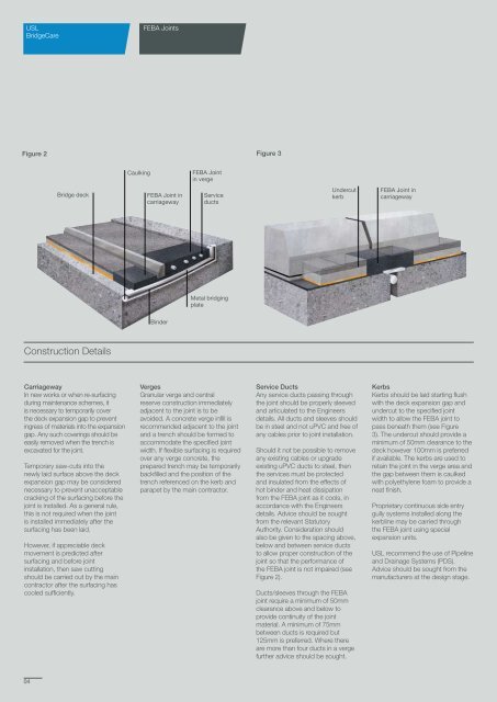
USLBridgeCare<strong>FEBA</strong> <strong>Joints</strong>Figure 2 Figure 3Caulking<strong>FEBA</strong> Jointin vergeBridge deck<strong>FEBA</strong> Joint incarriagewayServiceductsUndercutkerb<strong>FEBA</strong> Joint incarriagewayMetal bridgingplateBinderConstruction DetailsCarriagewayIn new works or when re-surfacingduring maintenance schemes, itis necessary to temporarily coverthe deck expansion gap to preventingress of materials into the expansiongap. Any such coverings should beeasily removed when the trench isexcavated for the joint.Temporary saw-cuts into thenewly laid surface above the deckexpansion gap may be considerednecessary to prevent unacceptablecracking of the surfacing before thejoint is installed. As a general rule,this is not required when the jointis installed immediately after thesurfacing has been laid.However, if appreciable deckmovement is predicted aftersurfacing and before jointinstallation, then saw cuttingshould be carried out by the maincontractor after the surfacing hascooled sufficiently.VergesGranular verge and centralreserve construction immediatelyadjacent to the joint is to beavoided. A concrete verge infill isrecommended adjacent to the jointand a trench should be formed toaccommodate the specified jointwidth. If flexible surfacing is requiredover any verge concrete, theprepared trench may be temporarilybackfilled and the position of thetrench referenced on the kerb andparapet by the main contractor.Service DuctsAny service ducts passing throughthe joint should be properly sleevedand articulated to the Engineersdetails. All ducts and sleeves shouldbe in steel and not uPVC and free ofany cables prior to joint installation.Should it not be possible to removeany existing cables or upgradeexisting uPVC ducts to steel, thenthe services must be protectedand insulated from the effects ofhot binder and heat dissipationfrom the <strong>FEBA</strong> joint as it cools, inaccordance with the Engineersdetails. Advice should be soughtfrom the relevant StatutoryAuthority. Consideration shouldalso be given to the spacing above,below and between service ductsto allow proper construction of thejoint so that the performance ofthe <strong>FEBA</strong> joint is not impaired (seeFigure 2).Ducts/sleeves through the <strong>FEBA</strong>joint require a minimum of 50mmclearance above and below toprovide continuity of the jointmaterial. A minimum of 75mmbetween ducts is required but125mm is preferred. Where thereare more than four ducts in a vergefurther advice should be sought.KerbsKerbs should be laid starting flushwith the deck expansion gap andundercut to the specified jointwidth to allow the <strong>FEBA</strong> joint topass beneath them (see Figure3). The undercut should provide aminimum of 50mm clearance to thedeck however 100mm is preferredif available. The kerbs are used toretain the joint in the verge area andthe gap between them is caulkedwith polyethylene foam to provide aneat finish.Proprietary continuous side entrygully systems installed along thekerbline may be carried throughthe <strong>FEBA</strong> joint using specialexpansion units.USL recommend the use of Pipelineand Drainage Systems (PDS).Advice should be sought from themanufacturers at the design stage.04