UNISORB AK Fixator System - Unisorb Installation Technologies
UNISORB AK Fixator System - Unisorb Installation Technologies
UNISORB AK Fixator System - Unisorb Installation Technologies

You also want an ePaper? Increase the reach of your titles
YUMPU automatically turns print PDFs into web optimized ePapers that Google loves.
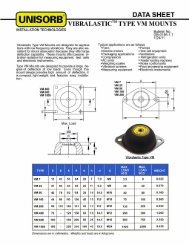
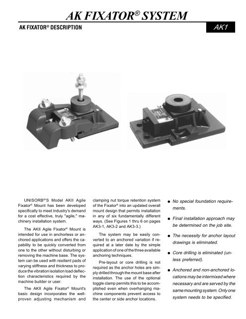
<strong>AK</strong> FIXATOR ® DESCRIPTION<strong>AK</strong> FIXATOR ® SYSTEM<strong>AK</strong>1<strong>UNISORB</strong> ® 'S Model <strong>AK</strong>II Agile<strong>Fixator</strong> ® Mount has been developedspecifically to meet industry's demandfor a cost effective, truly "agile," machineryinstallation system.The <strong>AK</strong>II Agile <strong>Fixator</strong> ® Mount isintended for use in anchorless or anchoredapplications and offers the capabilityto be quickly converted fromone to the other without disturbing orremoving the machine base. The systemcan be used with resilient pads ofvarying stiffness and thickness to producethe vibration isolation load deflectioncharacteristics required by themachine builder or user.The <strong>AK</strong>II Agile <strong>Fixator</strong> ® Mount'sbasic design incorporates the wellprovenadjusting mechanism andclamping nut torque retention systemof the <strong>Fixator</strong> ® into an updated overallmount design that permits installationin any of six fundamentally differentways. (See Figures 1 thru 6 on pages<strong>AK</strong>3-1, <strong>AK</strong>3-2 and <strong>AK</strong>3-3.)The system may be easily convertedto an anchored variation if requiredat a later date by the simpleapplication of one of the three availableanchoring techniques.Pre-layout or core drilling is notrequired as the anchor holes are simplydrilled through the mount base afterinstallation. The use of the optionaltoggle clamp permits this to be accomplishedeven when overhanging machinecomponents prevent access tothe center or side anchor locations.● No special foundation requirements.● Final installation approach maybe determined on the job site.● The necessity for anchor layoutdrawings is eliminated.● Core drilling is eliminated (unlesspreferred).● Anchored and non-anchored locationsmay be intermixed wherenecessary and are served by thesame mounting system. Only onesystem needs to be specified.
<strong>AK</strong> FIXATOR ® SPECIFICATIONS<strong>AK</strong>2See Figure 4See Figure 6<strong>AK</strong>II AGILE FIXATOR ® SYSTEM SPECIFICATIONSDescriptionDimensionsSee Figures 1, 2 & 5See Figure 3Recommended machine dead weight4,400 lbs.Maximum allowable lifting load per <strong>Fixator</strong> ®26,500 lbs.Spring Constant22,800,000 lb./in.Minimum available overall height3.31 in.Approximate torque required to turn adjusting screw1 ft. lb./1000 lbs. loadMaximum allowable torque on adjusting screw29 ft. lb.Vertical adjustment per revolution of height adjusting screw 0.010 in.Maximum vertical adjustment0.200 in.Minimum height with v = 84 Spherical Seat3.31 in.Minimum height with v = 95 Spherical Seat3.74 in.Minimum height with v = 101 Spherical Seat3.98 in.Minimum height with v = 107 Spherical Seat4.21 in.Total overall height range with standard components1.10 in.Base area of basic unit59.4 sq. in.Weight of basic unit19.2 lbs.Weight of Toggle Clamp13.4 lbs.Approximate torque on anchor bolt nut at yield point of bolt 217 ft. lbs.Approximate tension on anchor bolt at yield point19,800 lbs.Anchor specifications with uplift resistance:With side anchors19,800 lbs.With Toggle Clamp12,000 lbs. max.With 'wes' center anchor19,800 lbs.With 'wcs' center anchor12,000 lbs.Resilient pad specifications:Stiffness with 6 mm thick pad2,000,000 lbs./in. min.Stiffness with 2 mm thick pad6,000,000 lbs./in. minCoefficient of friction >0.7Internal damping coefficient >0.15
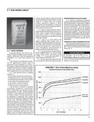
<strong>AK</strong> FIXATOR ® INSTALLATION METHODS<strong>AK</strong>3-1Figure 1.This method of installation simply setsthe <strong>AK</strong>II Agile <strong>Fixator</strong> ® on the Opt. 'Y'Resilient Pad. The pad has a coefficientof friction of approximately .70which will quite effectively prevent the<strong>Fixator</strong> ® from walking. The pad is availablein either a 2 mm or 6 mm thickness.The standard pad is supplied in90 durometer, but different durometersare available on a special order basis(contact <strong>Unisorb</strong> Engineering). An Opt.'STE' Hold Down Stud is used to securethe <strong>Fixator</strong> ® to the machine foot.This method should be used whensome degree of vibration isolation isdesired, and when extremely close tolerancesare not a consideration.FIGURE 1. 'STE' CENTER BOLT - FREE STANDINGFigure 2.This method of installation utilizes<strong>Unisorb</strong> ® Adhesive V-100 Epoxy Groutapplied beneath the <strong>Fixator</strong> ® . Pleasenote that a minimum thickness of .09"is recommended. This method alsouses the Opt. 'STE' Hold Down Stud.This stud is capable of stretching toallow adjustment after the anchor nut istightened. This method provides asimple and inexpensive, relatively secureinstallation without disturbing thefloor. Please note that this methodprovides no option for vibration isolation.FIGURE 2. 'STE' CENTER BOLT - GLUE DOWN
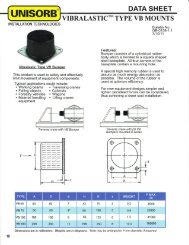
<strong>AK</strong> FIXATOR ® INSTALLATION METHODS<strong>AK</strong>3-2Figure 3.This method of installation utilizes four(4) <strong>Unisorb</strong> ® Capsule Anchors and StudAssemblies with two (2) located oneach side of the <strong>Fixator</strong> ® . The anchorsmay be installed after the <strong>Fixator</strong> ® is inplace. See page <strong>AK</strong>4-6 for instructionson installing these anchors. This methodalso uses the Opt. 'STE' Hold DownStud, and may use either the Opt. 'Y'Resilient Pad or the Adhesive V-100Epoxy Grout beneath the <strong>Fixator</strong> ® .6-½"7- 5 /8"4.75"FIGURE 3. SIDE CAPSULE ANCHOR STUDSFigure 4.This method of installation utilizes the<strong>Unisorb</strong> ® Toggle Clamp to hold downthe <strong>Fixator</strong> ® . The Toggle Clamp is helddown with two (2) <strong>Unisorb</strong> ® CapsuleAnchors and Stud Assemblies, onelocated on each side. See page <strong>AK</strong>4-6for instructions on installing these anchors.This method also uses the Opt.'STE' Hold Down Stud, and may useeither the Opt. 'Y' Resilient Pad or theAdhesive V-100 Epoxy Grout beneaththe <strong>Fixator</strong> ® .12-¼"C-12, C-587.50"FIGURE 4. TOGGLE CLAMP WITH CAPSULE ANCHOR STUDS
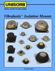
<strong>AK</strong> FIXATOR ® INSTALLATION METHODS<strong>AK</strong>3-3Figure 5.This method of installation utilizes asingle, center mounted <strong>Unisorb</strong> ® CapsuleAnchor and Stud Assembly tosecurely fasten the <strong>Fixator</strong> ® to the floor.The Capsule Anchor and Stud Assemblymay be installed either before orafter the <strong>Fixator</strong> ® is in place. The recommendedpractice, however, is toinstall the anchor prior to placing the<strong>Fixator</strong> ® . This installation method utilizeseither the Opt. 'Y' Resilient Pad orthe Adhesive V-100 Epoxy Grout andmay be utilized only if access to thecenter stud anchoring location is available.FIGURE 5. CENTER CAPSULE ANCHOR STUDFigure 6.This method of installation utilizes asingle, center mounted <strong>Unisorb</strong> ® Opt.'WES' Anchor Hold Down Stud. Thisstud is placed into a core drilled holeand secured with either <strong>Unisorb</strong> ® V-1cementitious or Standard V-100 EpoxyGrout. A <strong>Unisorb</strong> ® 12" x 15" GroutForm is used with this configuration.This method provides the most secureanchoring of all, and is recommendedwhen very close tolerances are requiredto be held, and when access tothe center anchoring location is available.Please note that this method providesno option for vibration isolation.FIGURE 6. 'WES' CENTER ANCHOR STUD
<strong>AK</strong> FIXATOR ® OPTION DETAILS<strong>AK</strong>4-1<strong>AK</strong>II AGILE FIXATOR BASIC UNIT
<strong>AK</strong> FIXATOR ® OPTION DETAILS<strong>AK</strong>4-2
<strong>AK</strong> FIXATOR ® OPTION DETAILS<strong>AK</strong>4-3
<strong>AK</strong> FIXATOR ® OPTION DETAILS<strong>AK</strong>4-2<strong>AK</strong>4-4
<strong>AK</strong> FIXATOR ® OPTION DETAILS<strong>AK</strong>4-5
<strong>AK</strong> FIXATOR ® OPTION DETAILS<strong>AK</strong>4-6<strong>UNISORB</strong> ® CAPSULE ANCHOR SYSTEMSWITH STUD ASSEMBLYThe <strong>Unisorb</strong> ® Capsule Anchor with Stud Assemblyoffers tremendous holding power which is strongerthan the concrete itself. A graded blend of quartzagregate transfers the pullout forces into the concrete.Since there are no expansive forces fromthe anchor systems, they can be placed near thefoundation edges, chip troughs, coolant trenchesor wireways. High anchor-to-concrete strengthsare developed which allow smaller anchor holesand smaller studs to be used than is possible withconventional expanding anchor type systems.SPECIFICATIONSANCHOR CAPSULE DRILL HOLE ANCHOR NO. † ULTIMATE ULTIMATESIZE* NUMBER DIAMETER* DEPTH* & LENGTH* TENSILE LOAD SHEAR LOAD3/8 C-38 7/16 3 1/2 S-38x5 1/8 7,820 lbs. 6,480 lbs.1/2 C-12 9/16 4 1/4 S-12x6 1/2 13,435 lbs. 11,120 lbs.5/8 C-58 11/16 5 S-58x7 5/8 20,585 lbs. 17,650 lbs.5/8 C-58 11/16 6 1/4 S-58x11** 34,780 lbs. 17,650 lbs.3/4 C-34 7/8 6 5/8 S-34x9 1/2 27,400 lbs. 27,385 lbs.7/8 C-78 1 7 S-78x10 1/4 35,090 lbs. 36,065 lbs.1 C-100 1 1/4 8 1/4 S-100x12 47,800 lbs. 53,135 lbs.1 1/4 C-114 1 1/2 10 1/4 S-114x15 70,100 lbs. 68,000 lbs.*All dimensions in inches. **High Strength StudMINIMUM CURE TIMESGLASS CAPSULELIQUID RESINQUARTZ AGGREGATECATALYSTCONCRETE TEMPERATURECURE TIMEOver 68°F (20° C)20 Minutes50°F to 68°F (10° to 20° C) 30 Minutes32°F to 50°F (0° to 10° C) 1 Hour23°F to 32°F (-5° to 0° C) 5 Hours†ULTIMATE TENSILE LOAD TEST DATATest results using 4,000 PSI concrete are given as a guide only.It is recommended that tests to simulate actual conditions becarried out to determine the suitability of Capsule Anchors forparticular applications.To order specify capsule, stud and drive unit.The <strong>Unisorb</strong> ® Capsule Anchor with Stud Assembly is asuperior method of heavy duty anchoring using a highstrength adhesive to retain a threaded rod and othermaterials such as rebar, in concrete and other masonrymaterial. The system consists of a glass capsule containingthe proper proportion of base resin, hardenerand aggregate for the anchor, appropriate length studwith washer and nut, and a drive unit to allow the studto be installed with a standard hammer drill.INSTALLATION INSTRUCTIONS1. Drill a clearance hole for the insert using a rotary hammer drillor core drilling equipment. Refer to the chart for properdiameter and depth for each anchor size and standard studmaterial (50,000 psi). Drill deeper holes when using hightensile strength studs or when close to the foundation edge,chip troughs or have extremely close spacing.2. Thoroughly clean the holes. Excessive dust will reduce theholding power of the anchor. For best results blow out theconcrete dust using compressed air or flush out with water.The strength of the bond will not be affected by wet or dampholes.3. Insert the capsule anchor.4. Assemble the drive unit into the hammer drill. Thread the nutonto the stud about one diameter and insert the stud into thedrive unit. The drive unit should shoulder on the nut for easeof removal. Drive the point end into the capsule. This actionwill break the glass tube and mix the components. Turn thedrill off immediately when the stud is fully inserted.5. Allow the anchor to cure about 1 1/2 minutes withoutdisturbing the drive unit. Two or more drive units may beconvenient for larger jobs. Remove the drill unit by placing awrench on the drive unit and another on the nut. Loosen,being careful not to disturb the stud. Allow the anchor to curefor the minimum time before using.